

Page 1

Series 3300
System Administration Manual
59040-00-90
Revision A - July, 1993
Page 2

© 1993 SYMBOL TECHNOLOGIES, INC.
No part of this publication may be reproduced or used in any form, or by any electrical
or mechanical means, without permission in writing from Symbol. This includes
electronic or mechanical means, such as photocopying, recording, or information
storage and retrieval systems. The material in this manual is subject to change without
notice.
The software is provided strictly on an “as is” basis. All software, including firmware,
furnished to the user is on a licensed basis. Symbol grants to the user a non-transferable
and non-exclusive license to use each software or firmware program delivered
hereunder (licensed program). Except as noted below, such license may not be
assigned, sublicensed, or otherwise transferred by the user without prior written
consent of Symbol. No right to copy a licensed program in whole or in part is granted,
except as permitted under copyright law. The user shall not modify, merge, or
incorporate any form or portion of a licensed program with other program material,
create a derivative work from a licensed program, or use a licensed program in a
network without written permission from Symbol. The user agrees to maintain
Symbol’s copyright notice on the licensed programs delivered hereunder, and to
include the same on any authorized copies it makes, in whole or in part. The user
agrees not to decompile, disassemble, decode, or reverse engineer any licensed
program delivered to the user or any portion thereof.
Symbol reserves the right to make changes to any software or product to improve
reliability, function, or design.
All rights reserved.
Symbol does not assume any product liability arising out of, or in connection with, the
application or use of any product, circuit, or application described herein.
No license is granted, either expressly or by implication, estoppel, or otherwise under
any Symbol Technologies, Inc., intellectual property rights. An implied license only exists for equipment, circuits, and subsystems contained in Symbol products.
Spectrum One is a trademark of Symbol Technologies. Other product names
mentioned in this manual may be trademarks or registered trademarks of their
respective companies and are hereby acknowledged.
Symbol Technologies, Inc.
116 Wilbur Place
Bohemia, N.Y. 11716
Page 3

FCC Requirements
This device must operate in compliance with Federal Communications Commission (FCC) Rules and Regulations Parts 15 and 68. See FCC registration label (located on bottom of equipment) for FCC registration and ringer equivalence (REN)
numbers.
Note: This equipment has been tested and found to comply with the limits for a
Class B digital device, pursuant to Part 15 of the FCC Rules. These limits are designed to provide reasonable protection against harmful interference when the
equipment is operated in a commercial environment. This equipment generates,
uses and can radiate radio frequency energy and, if not installed in accordance
with the instruction manual, may cause harmful interference to radio communications. Operation of this equipment in a residential area is likely to cause harmful
interference in which case the user will be required to correct the interference at
his own expense.
The REN is used to determine the quantity of devices which may be connected to
the telephone line. Excessive RENs on the telephone line may result in the devices
not ringing in response to an incoming call. In most, but not all, areas the sum of
the RENs should not exceed five. To be certain of the number of devices that may
be connected to the line, as determined by the total RENs, contact the telephone
company to determine the maximum REN for the calling area.
If the terminal equipment (see FCC registration label for equipment identification)
causes harm to the telephone network, the telephone company will notify you in
advance; however, if advance notice is not practical, the telephone company will
notify you as soon as possible. Also, you will be advised of your right to file a
complaint with the FCC if you believe it is necessary.
The telephone company may make changes in its facilities, equipment, operations
or procedures that could affect the operation of the equipment. If this happens,
the telephone company will provide advance notice so that you may make the
necessary modifications to maintain uninterrupted service.
ii
Page 4

Series 3300 System Administration Manual
Data Equipment
Data terminal equipment that has been registered must use the following jacks for
each type of operation: permissive - RJ11C, programmable - RJ41S and RJ458, fixed
loss loop - RJ41S.
Radio Interference Notice
This device complies with Part 15 of the FCC Rules. Operation is subject to the
following two conditions: (1) This device may not cause harmful interference, and
(2) This device must accept any interference received, including interference that
may cause undesired operation.
iii
Page 5

Service Information
In the event of equipment malfunction, all repairs of this equipment must be performed by Symbol Technologies, Inc. or an authorized agent; it is the user's responsibility to report the need for service to Symbol Technologies, Inc. or an
authorized agent. If the trouble is causing harm to the telephone network, the telephone company may request you to remove the equipment from the network until
the problem is resolved.
Service is available under various options: to determine which option is best for
you and where to obtain it, please call or write:
Symbol Technologies, Inc.
116 Wilbur Place.
Bohemia, NY 11716
U.S.A.
(516) 563-2400
If you need to ship a terminal to a Service Center, you must send it in an approved
container designed to prevent damage in transit. If the original container is not
available, ask your Service Center to order another.
Make sure the terminal is turned off when you pack it. Leave the battery pack installed so that it can be checked. A battery pack will be returned to you with the
terminal. Pack the terminal carefully. Fill out the prenumbered tag included with
the terminal when it was shipped to you. If the original tag is not available, ask
the Service Center for another.
Fill out the adhesive-backed portion of the shipping label with the address of your
Service Center. T ear off this portion of the label and place it on the outside of the
container. Remove your copy of the shipping tag and place the rest of the tag inside the container with the terminal.
If you need to contact the Service Center about a terminal you have shipped to
them, please be ready to give the shipping tag number to the Customer Support
Representative so your equipment may be located more easily.
iv
Page 6

Series 3300 System Administration Manual
Canadian Compliance
The Canadian Department of Communications label identifies certified equipment.
This certification means that the equipment meets certain telecommunications network protective, operational and safety requirements. The department does not
guarantee the equipment will operate to the user's satisfaction.
Before installing this equipment, users should ensure that it is permissible to be
connected to the facilities of the local telecommunications company. The equipment must also be installed using an acceptable method of connection. In some
cases, the company's inside wiring associated with a single line individual service
may be extended by means of a certified connector assembly (telephone extension cord). The customer should be aware that compliance with the above conditions may not prevent degradation of service in some situations.
Repairs to certified equipment should be made by an authorized Canadian maintenance facility designated by the supplier. Any repairs or alterations made by the
user to this equipment, or equipment malfunctions, may give the telecommunications company cause to request the user to disconnect the equipment.
Users should ensure for their own protection that the electrical ground connections of the power utility, telephone lines and internal metallic water pipe system,
if present, are connected together. This precaution may be particularly important
in rural areas.
Caution: Users should not attempt to make such connections themselves but
should contact the electric inspection authority or electrician, as appropriate.
The Load Number (LN) assigned to each terminal device denotes the percentage
of the total load to be connected to a telephone loop which is used by the device
to prevent overloading. The termination on a loop may consist of any combination
of devices subject only to the requirement that the total of the Load Numbers of
all the devices does not exceed 100. An alphabetic suffix is also specified in the
Load Number for the appropriate ringing type (A or B), if applicable. For example,
LN = 20 A designates a Load Number of 20 and an "A" type ringer.
v
Page 7

This equipment is a Class A digital apparatus which complies with Radio Interference Regulations, CRC c.1374.
Please contact your local Symbol Technologies, Inc. representative for support and
service.
Symbol Technologies, Inc.
Canadian Sales and Service
93 Skyway Avenue
Unit 106, Building B
Etobicoke, Ontario
Canada
Phone: 416 674-1497
European Service
For service in European countries, please contact:
Symbol Technologies, Inc.
13 Oaklands Park
Fishponds Road
Workingham
Berkshire, England RG11 2FD
Phone: 734-771399
vi
Page 8

vii
Page 9

Contents
About This Manual
Related Publications ...................................................................................xii
The Series 3300 System
Introduction ...............................................................................................1-1
Parts of the Series 3300 ............................................................................1-2
Accessories .................................................................................................1-3
Battery Chargers ...............................................................................1-3
Cradles .............................................................................................. 1-4
Scanners ............................................................................................1-5
Radio ................................................................................................. 1-5
Environment ..............................................................................................1-6
Intrinsically Safe Configurations ......................................................1-6
Storage .......................................................................................................1-7
Maintaining the Series 3300
Cleaning ..................................................................................................... 2-2
Maintaining Batteries .................................................................................2-3
Battery Life .......................................................................................2-3
When to Replace or Recharge Batteries .........................................2-4
Replacing the Battery Pack ..............................................................2-6
Replacing Alkaline Batteries ............................................................2-7
Charging the NiCad Battery Pack ....................................................2-8
Battery Charging Tips ......................................................................2-9
Lithium Backup Batteries ...............................................................2-10
vii
Page 10

Series 3300 System Administration Manual
Replacing Backup Batteries ...........................................................2-10
Initializing the 3300 .................................................................................2-12
Cancelling Communication ............................................................2-12
Communication Parameters ...........................................................2-12
Loading the Program ......................................................................2-12
Operating the Series 3300
Powering the 3300 On and Off ................................................................3-2
Normal Power On/Off .....................................................................3-2
Automatic Power-On/Off .................................................................3-2
Forcing Power Off ............................................................................3-3
Restarting After A Forced Power Off ..............................................3-3
Booting the 3300 .......................................................................................3-4
Warm Boot .......................................................................................3-4
Cold Boot ..........................................................................................3-5
Booting to Command Mode ............................................................3-6
Adjusting the Display ................................................................................3-7
Backlighting ......................................................................................3-7
Display Contrast ...............................................................................3-7
Scanning .....................................................................................................3-8
Scanning Tips ...................................................................................3-8
Attaching a Scanner .........................................................................3-9
Using a Laser Scanner ....................................................................3-10
The Series 3300 Keyboard ......................................................................3-13
Using the Keyboard....................................................................... 3-13
Modifier Keys .................................................................................3-15
Key Descriptions ............................................................................3-16
viii
Page 11

Error Recovery and Troubleshooting
Error Messages ..........................................................................................4-2
Troubleshooting ........................................................................................ 4-3
Startup Failures .......................................................................................... 4-4
Boot Failure Messages .....................................................................4-4
Self Test Function ...................................................................................... 4-5
Running the Self Test ......................................................................4-5
Self Test Summaries ......................................................................... 4-5
Keyboard Test.................................................................................. 4-6
Exiting Self Test ............................................................................... 4-7
Scanning Problems .................................................................................... 4-8
Memory Transfer Program ........................................................................4-9
Running Memory Transfer ..............................................................4-9
Port Pin-Outs
Contents
Scanner Port (DE-9) ..................................................................................A-1
COM1 Serial Port (DB-25) ........................................................................A-2
COM2 Serial Port Connector (RJ-41) ........................................................A-3
Null Modem ...............................................................................................A-4
Keyboard Layouts
Communications Status Codes
......................................................................................B-1
.............................................................C-1
ix
Page 12

Series 3300 System Administration Manual
x
Page 13

Series 3300 System Administration Manual
xi
Page 14

About This Manual
About This Manual
The Series 3300 System Administration Manual provides basic operational instructions required for tasks usually regarded as administrative. This includes general
care and use instructions, as well as instructions for booting, loading programs,
and troubleshooting the Series 3300 computer.
Manual Structure
This manual is divided into four chapters and three appendices:
Chapter 1
configuration options.
Chapter 2
including replacing and charging the batteries and downloading application
programs.
Chapter 3
various boot procedures, and miscellaneous information relevant to operating the
system.
Chapter 4
er suggestions towards identifying and correcting operational problems.
Appendix A
Appendix B
Appendix C
interpretation.
provides a brief overview of the Series 3300, including accessories and
provides instructions for initializing and maintaining the 3300,
describes basic operational procedures, including powering on and off,
describes some error messages, trouble shooting suggestions, and oth-
describes the pin assignments for Series 3300 ports.
illustrates the keyboard character assignments.
provides a table of communications status codes and their
xi
Page 15

Series 3300 System Administration Manual
Related Publications
PDT 3300 Quick Reference Guide (59040-00-89)
PRC 3310 Quick Reference Guide (59040-01-89)
Series 3300 with Integrated Scan Module Quick Reference Guide (59040-04-89)
Series 3000 System Software Manual (59045-00-94)
Series 3000 Application Programmer's Guide (59045-00-92)
Series 3000 Application Programmer’s Reference Manual (59045-00-93)
xii
Page 16

Chapter 1
The Series 3300 System
This chapter provides a brief overview of the Series 3300 system, accessories, and
options.
Introduction
The Series 3300 is an environmentally sealed, lightweight, battery powered, hand
held computer designed for use as a portable data collection device. Data can be
entered using the keyboard, a bar code scanner, or other devices. In many
applications, a Series 3300 computer is used as a remote terminal which is used
to collect and store data that is later uploaded to a host computer.
The Series 3300 uses the DR DOS™ operating system, which is compatible with
and extends the industry-standard IBM PC-DOS™. Using DR DOS provides access
to a number of commercially available programming tools. Additional programming tools, available from Symbol, make programming the system easier and provide access to special features.
Power saving features of the Series 3300 include auto-off and a power save mode
which reduce power consumption while waiting for an operator to provide input.
These features conserve battery power, lengthening the time between charges.
This high-performance computer supports many options, including a one-way
acoustic coupler, expansion memory, scanners, and an internal modem. The modular design provides flexibility in combining options to suit an application's needs.
Two models are currently available: the PDT 3300 and the PRC 3310. The primary
difference between the models is that the PRC 3310 has an internal radio transmitter/receiver.
1 - 1
Page 17
Series 3300 System Adminstration Manual
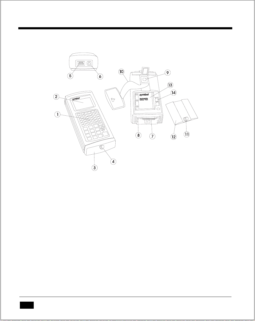
Parts of the Series 3300
Figure 1 - 1 Parts of the PDT 3300 (Standard end cap)
1. Keyboard (56 or 35 keys)
2. LCD display screen
3. Standard end cap (optical end cap not shown)
4. End cap latch
5. Scanner port (DB-9)
6. COM2 serial port (RJ-41)
7. COM1 serial port (DB-25)
8. Battery charger port
9. Internal modem port (optional)
10. Hand strap
11. Battery compartment latch
12. Battery compartment cover
13. Battery pack
14. Lithium backup batteries
1 - 2
Page 18
The Series 3300 System
Accessories
There are a variety of optional accessories available for the Series 3300.
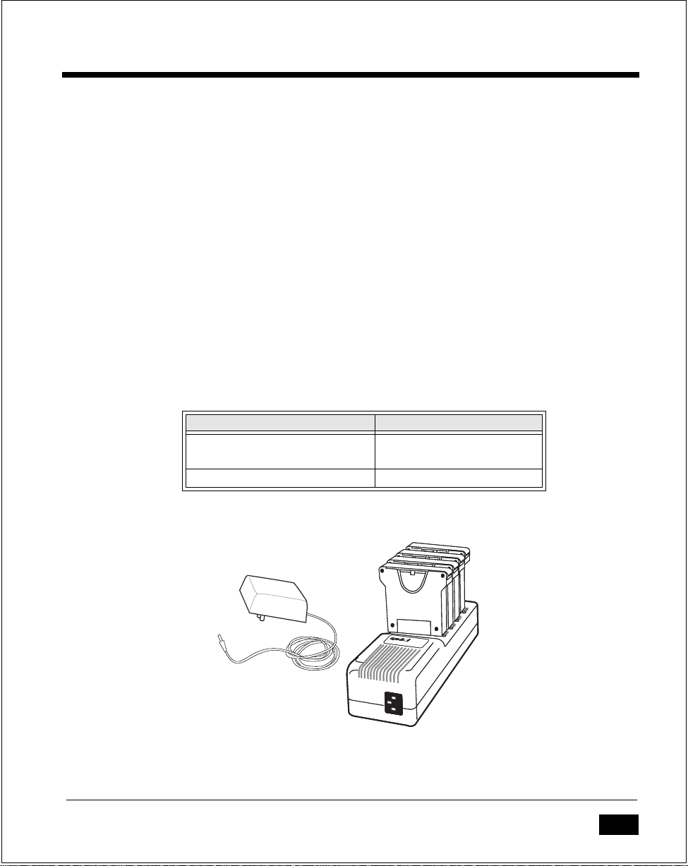
Battery Chargers
The Series 3300 can use rechargeable NiCad battery packs. Two types of battery
chargers are available from Symbol:
• The 12-V olt adapter charges the battery pack while the pack is in the 3300. The
adapter plugs into a 115V AC wall outlet and into the system (see Chapter 2).
• The Universal Battery Charger (UBC) charges up to four battery packs. The
packs must be placed in an adapter cartridge.
The batteries are also charged while the 3300 is placed in a cradle.
Table 1 - 1 Battery Charging Accessories
12Volt adapter 3042-06M (US version)
Universal Battery Charger 3004-110 (US version)
3004-220 (Int'l version)
UBC Adapter Cartridge 3004-003
Figure 1 - 2 Battery Chargers
1 - 3
Page 19
Series 3300 System Adminstration Manual
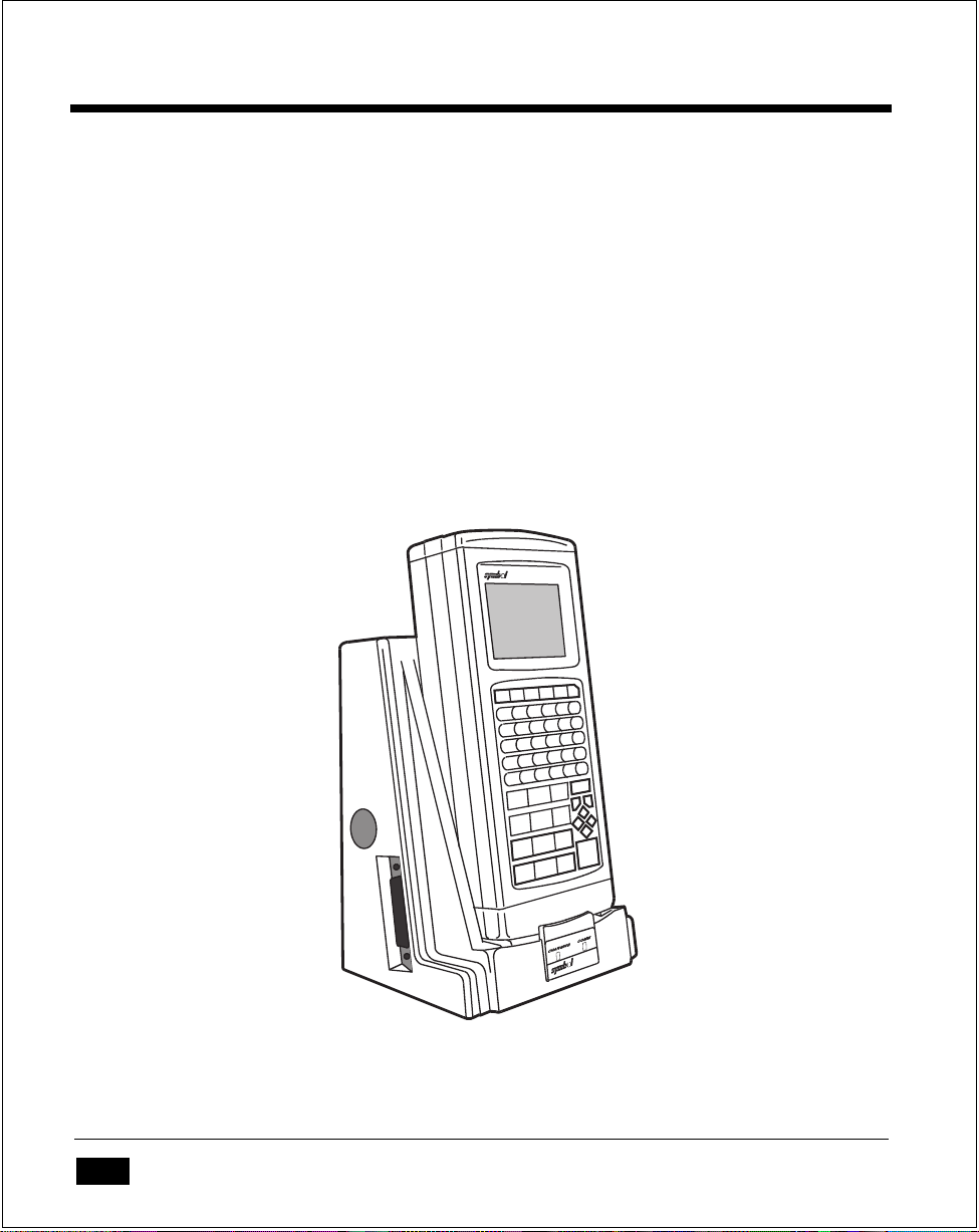
Cradles
A cradle is a communications device and battery charger combined. Cradles are
available with one or four slots.
When in a cradle, the terminal can communicate with the host computer over
serial or modem communication line. At the same time, the NiCad battery pack is
recharged. This simplifies many routine administrative tasks by eliminating the
need to connect cables to the terminal.
Communications between the terminal and the cradle are conducted via optical
signals. The terminal must have the optical interface installed, which includes a
special, non-removable end cap (optical end cap).
1 - 4
Figure 1 - 3 PDT 3300 in cradle
Page 20
The Series 3300 System
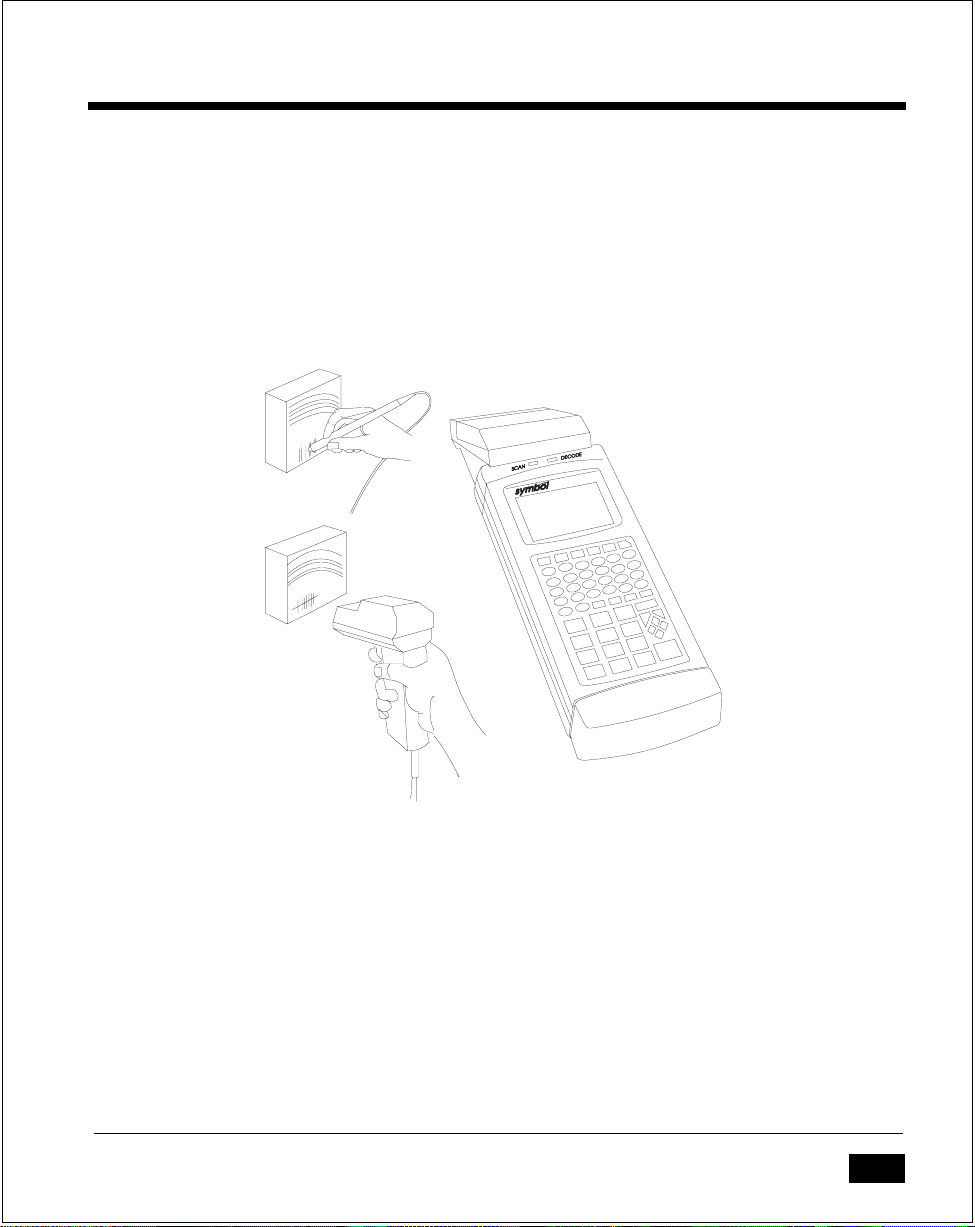
Scanners
A variety of scanning devices are available for use with the Series 3300, including
wand scanners and laser scanners.
Also available is an integrated scanner module which permanently attaches to the
terminal.
Figure 1 - 4 Scanners
Radio
The PRC 3310 includes an internal radio frequency transmitter/receiver, allowing
these systems to be used as part of a Spectrum One® network.
1 - 5
Page 21

Series 3300 System Adminstration Manual
Environment
The Series 3300 is intended to be used in an industrial environment. Table 1-2
summarizes the conditions under which the terminal is intended to operate.
Table 1 - 2 Environmental Specifications
Condition Range
Temperature range 32o to 122o F (0o to 50o Celsius)
Humidity 0 to 90% (non-condensing)
Max Static discharge 15 kilovolts
Altitude up to 10,000 feet.
Note that (1) batteries lose power faster at extremely high and low temperatures,
and (2) below 10oC, the LCD operates slowly.
Intrinsically Safe Configurations
Certain configurations of Series 3300 systems are certified for use in potentially
hazardous environments. These systems are specially ordered and configured for
such use.
Some procedures described in this manual should not be performed in potentially
hazardous environments. These procedures are noted with the following W arning:
Warning
This procedure is not approved for and should not be performed in potentially
hazardous environments.
1 - 6
Page 22

The Series 3300 System
Storage
If the 3300 will not be used for longer than a week, it should be stored in a cool,
dry place, away from dust. It is best to remove the battery pack and pack the terminal in its original shipping container.
If you are storing the terminal for a shorter period of time (a few days), you may
leave the batteries in the terminal.
1 - 7
Page 23

Series 3300 System Adminstration Manual
1 - 8
Page 24

Chapter 2
Maintaining the Series 3300
This chapter describes the basic procedures required to prepare and maintain a
Series 3300 terminal in operating condition. These procedures include:
• Cleaning the terminal
• Replacing and charging batteries
• Initializing the terminal by loading a program into memory.
2 - 1
Page 25

Series 3300 System Adminstration Manual
Cleaning
The 3300 requires a minimum amount of maintenance. Proper use and care of the
system will increase its life.
To clean the 3300, use a clean, soft cloth dampened with a mild cleaner, such as
soap and water.
Caution
Do not pour, spray, or spill any liquid onto any part of the 3300 or its peripheral
devices.
2 - 2
Page 26

Maintaining the Series 3300
Maintaining Batteries
Primary power for the Series 3300 is provided either by two 9-V olt alkaline batter ies in a carrier tray or by a rechargeable, nickel cadmium (NiCad) battery pack.
To prevent loss of data while replacing batteries, Series 3300 systems have two
lithium backup batteries. The backup batteries do not provide enough power to
operate the system.
Battery Life
The life of the primary battery pack is affected by many factors, including
temperature, the age of the batteries, and the data collection method. Battery life
is shortened by use in very high or very low temperatures, and by use of a
scanning device.
The approximate battery life between charges (NiCad) or replacement (Alkaline),
which reflects the data collection method, is summarized in Table 2-1. Note that
these values will vary with the application, and in particular, applications involving
modem and radio communications will shorten these times.
The lithium backup batteries provide sufficient power to preserve the contents of
memory for approximately approximately 300-400 hours.
Table 2 - 1 Battery Life
Battery Type Input Method Apx. Operating Time*
Alkaline Keyboard 95 hours
Laser Scanner 21 hours
Wand Scanner 32 hours
NiCad Keyboard 80 hours
Laser Scanner 19 hours
Wand Scanner 28 hours
*ˇActual operating time varies, depending on the application complexity.
Note
Alkaline batteries are NOT recommended for use with the PRC 3310 except in
case of emergency, due to the increased power consumption of the radio.
2 - 3
Page 27
Series 3300 System Adminstration Manual
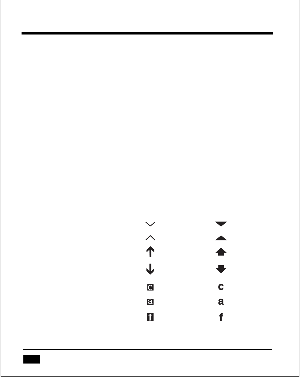
When to Replace or Recharge Batteries
The Series 3300 provides two types of indicators to notify you when battery power
is running low: warning messages and modified cursors (see Table 2-2). These
indicators may be changed or disabled by an application program.
•
LOW POWER
Table 2-2. Depending on the configuration (if ERR3000 is loaded), the message
LOW BATTER Y is also displayed. At this level, the 3300 continues to operate,
but there is probably less than one hour of usable power left.
•
VERY LOW
message is displayed briefly and the system powers off. You must replace or
recharge the batteries before continuing to use the 3300.
•
DEAD LITHIUM
power. These should be replaced as soon as possible to prevent loss of data
when the primary pack requires replacement.
- When the battery is low, the cursor changes, as shown in
- When the power becomes very low, the REPLACE CELLS
- The lithium batteries are too low to provide backup
Table 2 - 2 Normal and Low Power Cursors
2 - 4
Keyboard State Cursor Character Low Battery
Unshifted
Shifted
Momentary Shifted
Momentary Unshifted
Control
Alt
Function
Page 28

Maintaining the Series 3300
Replacement Batteries
NiCad battery packs are available from Symbol Technologies:
• Standard systems: product numbers 3045-005 and 3045-010
• Intrinsically safe systems: product number 3045-006
9-V olt alkaline batteries vary slightly in size, so some may not make good electrical
contact. The following batteries are known to be the proper size, and so are
assured to work:
• Eveready #522
• Duracell #MN1604 and #MN1604-AS
• Panasonic 6LR61 (6AM6).
Caution
Alkaline batteries are not approved for use in Intrinsically Safe systems.
2 - 5
Page 29

Series 3300 System Adminstration Manual
Replacing the Battery Pack
To remove and replace the primary battery pack, do the following (refer to Figure
2-1):
Warning
This procedure is not approved for and should not be performed in potentially
hazardous environments.
1. Turn the terminal OFF.
12
VDC
2 - 6
AB
D
Figure 2 - 1 Removing Battery Pack
E
Page 30

Maintaining the Series 3300
2. Unlock the end cap latch and remove the end cap to release the hand strap
(Figure 2-1A and B). If the system has an optical end cap, the strap unhooks
at the top.
3. Unlock the battery cover latch and remove the battery compartment cover
(Figure 2-1C and D).
4. Tip out the NiCad battery pack. If the system is using 9-V olt alkaline batteries,
squeeze the top and bottom of the battery carrier tray to release the catches
and lift out the tray (Figure 2-1E).
Caution
Dispose of dead batteries in accordance with local hazardous material laws.
5. Install a fully charged battery pack or the battery tray with new alkaline
batteries in the battery compartment and replace the battery compartment
cover.
Replacing Alkaline Batteries
Alkaline batteries must be held in the carrier tray. To replace the batteries, do the
following:
1. Remove the old batteries from the holder one at a time.
2. Install each new battery with the + and - signs in the correct direction, as
indicated on the battery tray.
3. Install the batteries and tray in the battery compartment and replace the battery
compartment cover.
Caution
Use only Eveready #522, Duracell #MN1604 or #MN1604-AS, or Panasonic
6LR61(6AM6) alkaline batteries. Others may be slightly smaller, and not make
good electrical contact.
2 - 7
Page 31

Series 3300 System Adminstration Manual
Charging the NiCad Battery Pack
The NiCad battery pack can be recharged while it is in or out of the system.
To charge the battery pack external to the system, use the Symbol Universal
Battery Charger. Up to four NiCad packs can be charged at one time using this
charger.
If the system is equipped with the optical end cap, recharging begins when the
3300 is placed in a properly set up cradle. Refer to the cradle documentation for
additional information.
To charge the NiCad batteries in the 3300 using the 12V adapter, do the following
(refer to Figure 2-2):
Warning
This procedure is not approved for and should not be performed in potentially
hazardous environments.
1. Turn the system off.
2. Unlock and remove the end cap and locate the battery charger port.
3. Plug the charger end of the adapter into a wall socket.
4. Plug the cable end into the 3300's battery charger port.
5. After 12 to 16 hours, disconnect the charger cable from the system and the wall
outlet.
The 3300 may be used while the battery is being charged.
2 - 8
Page 32

Figure 2 - 2 Charging NiCad Pack Using Adapter
Battery Charging Tips
Maintaining the Series 3300
For maximum capacity and battery life, follow these helpful hints:
o
• Charge at temperatures between 0
• Recharge as soon as you see the "Low Battery" message.
• Recharge primary batteries after storage.
• If you find that your battery pack begins to need recharging more often, let it
discharge as completely as possible, then recharge it for at least 16 but not
more than 24 hours. Undercharging and overcharging can shorten the life of
your battery pack.
C and 45oC (32oF to 113oF).
2 - 9
Page 33

Series 3300 System Adminstration Manual
Lithium Backup Batteries
The Series 3300 use two CR1/3N cylindrical lithium batteries (product number
3027-160) as backup power. The backup batteries provide enough power to
maintain the contents of memory (RAM, including the RAM disk) for
approximately 300 to 400 hours.
Depending on the system configuration, the "Dead lithium" message may display
when the backup battery power is low.
Replacing Backup Batteries
It is recommended that you upload any data in memory to the host computer
before replacing the backup batteries.
To retain programs and data in RAM while replacing the backup batteries, it is
necessary to have main power applied. If the 3300 has the standard end cap (nonoptical), you can plug in the 12 volt adapter to provide power. Otherwise, it is
necessary to have charged main batteries in place.
Caution
When both main and backup power are removed at the same time, RAM
contents are lost.
To replace the lithium batteries, do the following:
Warning
This procedure is not approved for and should not be performed in potentially
hazardous environments.
1. Unload any data, using methods provided by the application program.
2. Turn the system off.
3. Remove the primary battery pack, as described earlier in this chapter.
2 - 10
Page 34

Maintaining the Series 3300
4. Locate the lithium backup batteries next to the battery pack compartment
(Figure 2-3). Remove the backup batteries by pulling the ribbon handles.
Back of
Terminal
Lithium
Batteries
Figure 2 - 3 Location of Lithium Batteries
Caution
Dispose of dead batteries in accordance with local hazardous material laws.
5. Insert the new lithium backup batteries into the placement socket with the
ribbon handle on the top.
6. The lithium batteries must be installed with the + and - signs on the battery on
the same side as the + and - signs inside the backup battery compartment. The
batteries must be installed with correct polarity for the system to operate.
7. Reinsert the primary battery pack and close the battery compartment.
If necessary, you can now download a new copy of the program.
2 - 11
Page 35

Series 3300 System Adminstration Manual
Initializing the 3300
Before the 3300 is ready to use, it must be initialized by loading the application
program. The program is stored in the terminal in non-volatile memory (NVM, also
called the application EEPROM). The program is transferred from a host computer
to the terminal over a communications line provided by either a null modem cable
or a cradle.
The procedure described here uses the sendhex command on the PC and the Program Loader function on the terminal. For details on the sendhex command, refer
to the Series 3000 Application Programmer's Manual. Other software may be used
in place of sendhex.
Cancelling Communication
At any time during the communication session, you can cancel communications
by pressing Clear on the 3300. The session stops immediately.
Communication Parameters
The communication parameters specified on the host and the 3300 must match.
Typical parameters are:
38400 bps
7 bit data
Odd parity
Xon/Xoff flow control
Loading the Program
A direct connection between the Series 3300 and the host PC is made with a null
modem cable (Symbol product number 3057-F03). The cable has a male DB-25
connector at one end and a female DE-9 connector at the other end.
To download the program, do the following:
2 - 12
Page 36

Maintaining the Series 3300
.
Figure 2 - 4 Communication and Charger Connections
Warning
This procedure is not approved for and should not be performed in potentially
hazardous environments.
1. Power OFF the 3300 and host PC.
2. Attach the male connector end to the 3300 and the female end to the host's
serial port (Figure 2-4).
3. Power up the PC and start the communication program. If you use the sendhex
command with the null modem connected to COM2, enter:
cd \
sendhex pgmname 38400 com2
Do not include the .hex extension on the program name.
2 - 13
Page 37

Series 3300 System Adminstration Manual
Once correctly started, sendhex displays a prompt to press Enter to begin
communications. You will start communications later (step 11).
Only the baud rate and comm port can be set by sendhex (defaults are 9600
bps and com1). Change these parameters as shown in the example. Other parameters are set to 7 data bits, odd parity, and Xon/Xoff flow control (version
3.0).
Note
Versions of sendhex earlier than 3.0 do not support flow control. If you use an
earlier version and encounter communication errors, use a lower baud rate.
4. Boot the 3300 to command mode (refer to Chapter 3):
56-key: On/Off and A+D
35-key: On/Off and BkSp+Shift
After booting, the terminal displays the function selector screen:
COMMAND MODE
Select function
Self Test
5. Use the up or down cursor keys to scroll through the command mode options
until "Program loader" is displayed, and press Enter.
6. The original contents of NVM (an EEPROM) must be erased before loading the
new program. The terminal displays:
Program loader
WARNING: EEPROM
WILL BE ERASED
CONTINUE? <ENT>
Note
To cancel this operation, press Clear.
Press Enter to erase the EEPROM. Wait while the EEPROM is erased.
2 - 14
Page 38

Maintaining the Series 3300
Once erasing the EEPROM is completed, the program prompts for the communications parameters.
7. Baud Rate. The baud rate screen is displayed:
Comm Parameters
Baud
4 9600
Use the up or down cursor key to scroll through the list of baud rates. When
the correct rate is displayed (38400 is recommended), press Enter.
8. Data Bits. The data bits screen is displayed:
Comm Parameters
Data Bits
7
Press 7 (recommended) or 8 to specify the data bits, or use the up and down
arrows. When the correct value is displayed, press Enter.
Note
If you select 8 data bits, the program selects "No parity" and skips the next step.
9. Parity. If you selected 7 data bits, the parity screen is displayed:
Comm Parameters
Parity
Odd
Press the first letter of a parity option (Even, Odd, None, Space, or Mark), or
use the up and down arrows to display a parity option, and press Enter.
2 - 15
Page 39

Series 3300 System Adminstration Manual
10. Flow Control. The flow control screen is displayed:
Comm Parameters
Flow Control
None
Press the first letter of a flow control option (None, Xon/Xoff, or RTS/CRS),
or use the up and down arrows to display a flow control option, and press
Enter.
Starting Communications
The 3300 is now ready to receive the program from the host PC. The 3300 displays:
Comm Parameters
Start? <ENT>
11. Press Enter on the 3300. The terminal waits a few seconds for the host PC to
initiate communications. While waiting, the 3300 displays:
Awaiting DSR
12. Press Enter on the host computer. Sendhex will begin transmitting the pro-
gram image.
When communications are established, the 3300 displays the following:
Program loader
Receiving: XXXX
While the program is loading, the display shows the segment address currently
being transferred (XXXX).
2 - 16
Page 40

Maintaining the Series 3300
13. When the transmission is complete, the 3300 displays a transmission status
screen:
Program loader
Status 0000
A Status of 0000 (all zeros) indicates that the transfer was successful. Other
status values are described Appendix C.
Ending Communications
To return to the Command Mode main menu, press Clear on the 3300.
Turn the terminal off and detach the communications cable.
To start the software running, reboot the terminal using the cold boot sequence
(refer to Chapter 3):
56-key: On/Off and Enter+F1+F4
35-key: On/Off and Space+Func+UpArrow
2 - 17
Page 41

Series 3300 System Adminstration Manual
2 - 18
Page 42

Chapter 3
Operating the Series 3300
This chapter describes the basic operations involved in using the Series 3300,
including:
• Powering the 3300 on and off
• Booting the terminal
• Adjusting the display
• Scanning
• Using the keyboard
3 - 1
Page 43

Series 3300 System Administration Manual
Powering the 3300 On and Off
Since the Series 3300 is a battery powered system, it is important to save as much
power as possible. The period of time that the 3300 can be used before its batteries
must be recharged or replaced can be increased by turning it off when data is not
being entered.
When powered off, the 3300 saves power by not performing any processing or
display functions. However, any programs or data in the system's memory are
retained. When the 3300 is powered up again, the display is restored and
processing continues at the point where it was when the terminal was powered
down.
Powering the 3300 on does not reset the system or its program. When you turn
the system back on, it's program will normally resume in the same place where it
was when it was powered off. The data stored in memory also remains intact.
Before the 3300 powers up, it checks the batteries for enough power to ensure
reliable operation and data storage.
Normal Power On/Off
To turn the 3300 on or off, press On/Off.
Automatic Power-On/Off
A number of other events may turn the 3300 on or off, depending on the application program. Some of these are:
• The system may power on when a key other than On/Off is pressed.
• The system may power on when the scanner trigger is pressed.
• The program may power on the system at a preset time to perform unattended
operations such as an overnight communications session.
• The program may power on the system to respond to a modem ring or an RS232 device connecting to the DB-25 connector.
• The system may power off automatically if it is not used for some period of
time, as determined by the program.
3 - 2
Page 44

Operating the Series 3300
Forcing Power Off
If the 3300 hangs, simply pressing the On/Off will not power it off. In this case,
the system can be forced to power off in order to reduce the drain on the batteries
until the data can be downloaded to the host system.
To force the system to power off, press and hold the On/Off key for 15 seconds.
Since the 3300 is still hung at this time, turning the power back on will not solve
the problem. To recover the data held in memory, you must perform a W arm Boot
(refer to the next section).
Restarting After A Forced Power Off
If an operator is forced to power down the 3300 because of defective software,
the System Administrator should restart the system following the warm or cold
boot procedures given below.
Note
Do not simply use the power key to restart if the 3300 was forced off due to
defective system or application program software in NVM; pressing On/Off will
only cause the program to resume where it left off, trying to perform the same
unsuccessful operation.
If the failure is due to an application program, use the warm boot procedure. If
this does not restart the system, follow the cold start procedure.
If the failure is due to system software in NVM, you will need to load a corrected
version of the program. Refer to Chapter 2 for loading instructions.
3 -3
Page 45

Series 3300 System Administration Manual
Booting the 3300
Powering on the Series 3300 does not boot the system, and so does not initialize
either the program or data. When it is necessary to initialize the 3300, either a
warm boot or a cold boot must be performed.
Warm Boot
A warm boot resets the operating system while preserving the program and data
on the RAM disk. This process is similar to pressing the Ctrl+Alt+Del keys on a PC,
except that it does not clear the system's memory. To perform a warm boot, power
off the system, and then follow these steps.
On the 56-key keyboard:
1. Press and hold down On/Off.
2. Press and hold L and Shift.
3. Release On/Off, and then release L and Shift.
On the 35-key keyboard:
1. Press and hold down On/Off.
2. Press and hold / and +.
3. Release On/Off, and then release / and +.
The 3300 then displays copyright, RAM size, expanded memory RAM size, and so
on, depending on the system's configuration.
3 - 4
Page 46

Operating the Series 3300
Cold Boot
A cold boot fully resets the system and clears memory, including clearing the RAM
disk. Any programs and data that have been stored in memory or on RAM Disk
are deleted. The NVM (Application EEPROM), however, is not affected.
Caution
This procedure erases all data and programs residing in dynamic memory and
RAM Disk. All contents of the RAM disk will be lost.
To perform a cold boot, power off the system and then follow these steps.
On the 56-key keyboard:
1. Press and hold On/Off.
2. Press and hold Enter, F4, and F1.
3. Release On/Off, and then release Enter, F4, and F1.
On the 35-key keyboard:
1. Press and hold On/Off.
2. Press and hold Space, Func, and UpArrow.
3. Release On/Off and then release Space, Func, and UpArrow.
The 3300 will display a copyright message, amount of RAM and expanded
memory. Other messages will be displayed as well, depending on the system
configuration.
3 -5
Page 47

Series 3300 System Administration Manual
Booting to Command Mode
Command Mode provides functions for:
• Running the Self-Test program to verify that the hardware is operating properly (refer to Chapter 4)
• Performing a Memory Transfer to upload data from the 3300 to the host system
(refer to Chapter 4)
• Performing a Program Download to transfer an application program from the
host system to the 3300 (refer to Chapter 2).
To boot to Command Mode, power the system off, then perform the following
steps.
On the 56-key keyboard:
1. Press and hold On/Off.
2. Press and hold A and D.
3. Release On/Off, and then release A and D.
On the 35-key keyboard:
1. Press and hold On/Off.
2. Press and hold BackSpace and Shift.
3. Release On/Off, and then release BackSpace and Shift.
The 3300 displays the following:
COMMAND MODE
Select function
Self test
3 - 6
Page 48

Operating the Series 3300
Adjusting the Display
Backlighting
The 3300's display has a light to illuminate the display in dimly lit areas.
To turn the backlight on or off, press:
56-key: Func and L
35-key: Func and ' (apostrophe)
The light also turns off when the 3300 is powered off.
Display Contrast
The contrast of the LCD display can be adjusted, making the display more readable
in different lighting conditions and at different viewing angles. Lightening and
darkening the display (decreasing and increasing contrast) is changed in steps.
To increase contrast (darken) one step:
56-key: Func then Space
35-key: Func then .
To decrease contrast one step:
56-key: Func then Bksp
35-key: Func then _
3 -7
Page 49

Series 3300 System Administration Manual
Scanning
In addition to keyboard data entry, the Series 3300 supports the use of barcode
scanning devices as an alternate input device. The application program must implement routines for barcode scanning before scanning can actually be performed.
Scanners supported by the 3300 include wand scanners and laser scanners. An option on the 3300 is an integrated laser scanner, which is a permanently installed
option.
Caution
Only scanners designated as Intrinsically Safe with the PDT 3300 may be used
in potentially hazardous environments.
Scanning Tips
Bar code labels that do not meet established industry specifications may not scan
successfully. These labels may include:
• Smudged labels
• Very dark or very light labels
• Highly reflective surfaces or coatings
• Poor color contrast.
The following may also cause unsuccessful scans:
• Moving the contact wand scanner too quickly
• Moving the contact wand scanner too slowly
• Moving the contact wand scanner at an uneven speed
• Moving the scanner diagonally across the bar code.
3 - 8
Page 50

Operating the Series 3300
Attaching a Scanner
To attach a wand or laser scanner to a Series 3300, do the following:
Warning
This attachment procedure is not approved for and should not be performed in
potentially hazardous environments.
1. Turn the system off.
2. Find the rubber boot (provided with the 3300) with two connector access
holes. Slip the larger hole of the rubber boot over the scanner's DE-9 connector (Figure 3-1).
3. Remove the rubber cover from the top of the 3300 and attach the DE-9 plug.
Slide the rubber boot down over the connector plug and ensure it is firmly
seated to create a watertight seal (Figure 3-2).
Figure 3 - 1 Installing the Rubber Boot
Figure 3 - 2 Connecting Scanner
3 -9
Page 51

Series 3300 System Administration Manual
Using a Laser Scanner
Laser scanners can be either detachable units, like the LS2000, or the Integrated
Laser Scan Module which is permanently attached to the terminal.
Scanning is activated by pulling the scanner trigger when the program prompts for
scanned data. Instead of using a trigger, a scanner may use a "soft trigger," with
one or more keyboard keys defined to serve as the trigger. The Integrated Scanner
Module requires the soft trigger since it does not have a trigger switch. The Enter
key is the default soft trigger key.
To enable the soft trigger, the STG3000.EXE program must be loaded with the
terminal software. Up to twenty keys can be defined as soft triggers. Refer to the
Series 3000 Application Programmer's Manual for more information on this
program.
To use a laser scanner, do the following (refer to Figures 3-3 and 3-4):
Warning
Do not look directly into the laser beam or point it at another person. Lasers can
cause eye damage.
1. Power on the system and scanner by pressing On/Off or pulling the scanner
trigger.
2. Point the scanner at the bar code and pull the trigger or press the soft trigger
key (Enter).
3. Adjust the aim so that the thin, red laser beam covers the entire length of the
bar code.
When the bar code is successfully decoded, the code is displayed on the 3300
screen. A beep may also indicate a successful scan.
The optimal scanning distance (focal length) for the Integrated Scanner Module is
.75 to 25 inches. For the optimal scanning distance of a detachable scanner, consult the scanner operator's manual.
3 - 10
Page 52

Operating the Series 3300
Figure 3 - 3 Using a Laser Scanner
Figure 3 - 4 Using the Integrated Scanner Module
3 -11
Page 53

Series 3300 System Administration Manual
Using a Contact Wand Scanner
To use a contact wand scanner, do the following:
1. Turn the system on.
2. Lightly touch the bar code with the tip of the wand, holding it at a 0- to 45degree angle above or below the line of the bar code (see Figure 3-5). The
best angle depends on the bar code.
3. Draw the scanner smoothly and at a moderate speed from right to left or from
left to right across the entire bar code.
When the bar code is successfully decoded, the code is displayed on the screen.
Depending on the program, a tone indicates a successful scan.
3 - 12
Figure 3 - 5 Using a Wand Scanner
Page 54

Operating the Series 3300
The Series 3300 Keyboard
The keyboard is the primary means for entering data and issuing commands on
the Series 3300. The standard 56-key and 35-key keyboards are illustrated in
Figures 3-6 and 3-7, respectively.
The keys on the keyboard are distinguished as modifier keys and character keys.
Because the 3300 keyboards have fewer keys than PC keyboards, each character
key can produce more than the usual one or two characters. The four modifier
keys, Shift, CapsLock (Alpha on the 35-key keyboard), Ctrl and Func, used
individually or in combinations, determine which character or special function is
produced by the character keys.
Using the Keyboard
Except for boot operations, the Series 3300 expects keys to be pressed one at a
time. Depending on the configuration (whether ERR3000 is loaded), the system
may indicate a Double Key error if two or more keys are pressed simultaneously.
Accordingly, all key sequences must be entered by pressing and releasing one key
before pressing the next.
The keyboard also has an optionally configurable auto-repeat function. If set,
when the operator presses a character key and holds it, the character is repeated
as long as the key is held. If the key is pressed immediately following a modifier
keys, the modifier sequence affects only the first occurrence of the character key.
For example, Shift followed by pressing and holding A generates: Aaaaaa...
3 -13
Page 55

Series 3300 System Administration Manual
F1
F2
F6
G
menu
send
YZ
7
4
123
-
No
F3
F7
F8
HI J
help
NM
O
TS
U
+
Caps
lock
8
56
0
F4
F5
F9
DCBA
On
F10
Off
FE
K
L
lamp
PQR
VWX
Func Ctrl Shift
9
Clear
Sp
dark
Bksp
light
Enter
Yes
=
3 - 14
Figure 3 - 6 56-key Keyboard Legend
SPACE
ALPHA
[
]
ABCD
EF
*
/
J
KLMN
OPQ
7
89
RST
5
4
U
123
Help
.
Dark Send
VW
XYZ
0
SHIFT
’
,
G
Menu
6
_
Light
CTRL
FUNC
On
=
HI
;
\
+
CLEAR
BKSP
E
N
T
E
R
Off
Figure 3 - 7 35-key Keyboard Legend
Page 56

Operating the Series 3300
Modifier Keys
The Shift, CapsLock (56-key keyboard), Alpha (35-key keyboard), Func, and
Ctrl keys are modifier keys. When pressed individually or in certain combinations,
these keys change the keyboard state and possibly the character produced by the
following character key.
For example, on the 56-key keyboard, the Shift key causes the letter keys to gen-
erate upper-case letters. On the 35-key keyboard, Alpha causes the character keys
to produce letters. (Alpha, like CapsLock, shifts the keyboard so only upper-case
letters are produced. Lower case letters are not available on the 35-key keyboard.)
Pressing Func followed by Ctrl produces Alt characters, just like the Alt key on a
PC.
Appendix B shows the characters and operations produced by sequences of
modifier keys on the standard 3300 keyboards. These key assignments may be
changed by an application program. Refer to the application program
documentation for any special key assignments.
The CapsLock and Alpha keys affect all succeeding character keys until
CapsLock or Alpha is pressed again. The other modifier keys affect only the next
character key.
The current keyboard state is indicated by the cursor shape, unless changed by
the application. The standard cursor shapes are shown in Table 2-2.
To cancel the effect of a modifier key, press it again.
3 -15
Page 57

Series 3300 System Administration Manual
Key Descriptions
Most of the keys are self-explanatory; letter keys produce letters, number keys produce numbers. Table 3-1 describes the special functions performed by the 35-key
and 56-key keyboards.
Table 3 - 1 Special Keys
Key Name Description
Shift Changes letter keys to uppercase, and number keys to
punctuation marks and symbols.
Caps Lock (56-key keyboard) Shifts the keyboard between uppercase
and lowercase letters.
Alpha (35-key keyboard) Shifts the keyboard to produce alphabetic
characters. Uppercase only.
Func Function key. Invokes special keyboard functions.
Ctrl Control key. Generates control characters.
F1-F5
F6-F10
Enter Usually pressed after typing data or a command.
Help Displays a help message.
Lamp Turns on the backlight.
Menu Displays a menu.
Send Sends data to the host.
Clear
(Escape)
Dark Following Func, darkens the display (increases contrast).
Light Following Func, lightens the display (reduces contrast).
No Answers NO to a question.
Yes Answers YES to a question.
Function keys. The use of these keys is determined by the
application program.
Depending on the application, completely or partially
escapes from an application level or screen, or clears data
entered in a field.
3 - 16
Page 58

Chapter 4
Error Recovery and Troubleshooting
This chapter provides information to assist in basic trouble analysis and correction, including:
• Error messages
• Troubleshooting startup failures
• Running the Self Test function
• Scanning problems
• Running Memory Transfer
4 - 1
Page 59

Series 3300 System Administration Manual
Error Messages
Depending on the system configuration (if ERR3000 is loaded), the messages listed
in Table 4-1 may be displayed indicating that an error condition exists which will
affect the system's performance. A message is usually accompanied by one or
more beeps, after which the system returns to its previous status.
The actual wording of the messages may be changed by the application program,
so regard the messages here as representative. Some or all of these messages may
also be disabled by the application. Refer to the application documentation for further information.
Table 4 - 1 Error Messages
Message Explanation
Double Key
Error
Low Battery The battery pack should be recharged or
Replace Cells Replace or recharge the battery pack
Power Fault The last power off was caused by a power
Two or more keys were pressed at the same
time. This does not include boot sequences
(see Chapter 3).
replaced as soon as possible.
immediately. After this message is displayed,
the system shuts off. You will not be able to
power it on again until the battery pack is
charged.
failure. This occurs, for example, if the battery
pack is removed while the 3300 is on or the
batteries fail suddenly.
4 - 2
Page 60

Error Recovery and Troubleshooting
Troubleshooting
Table 4 - 2 Troubleshooting Chart
Symptom Possible Cause Suggested Action
Display is blank Battery pack is dead or missing. Replace or recharge
battery pack.
3300 does not
respond when
keys are pressed
Scanner will not
operate
Time and date
are incorrect
Application program was not downloaded
successfully.
Application Program was not downloaded
successfully.
Scanner connection is loose or
disconnected.
Scanner is broken. Replace scanner.
Scanning head needs cleaning. Clean scanner head.
Bar codes do not meet industry standards. Try scanning a different
Real-time clock needs to be reset. See the application
Repeat downloading.
Repeat downloading.
Reconnect scanner
cable.
bar code.
guide for instructions.
4 - 3
Page 61

Series 3300 System Administration Manual
Startup Failures
If a cold boot does not successfully start the application, either the application, the
system software, or the system is malfunctioning.
If you can boot the system to command mode, try the following:
• Use the Program Loader function to download a new version of the system
software to NVM. This procedure is described in Chapter 2.
• Use the Self Test function to check if the system hardware is operating properly. This procedure is described later in this chapter. After downloading new
system software, warm boot the 3300.
Boot Failure Messages
During a cold boot, the system briefly displays a status line for each driver as it
loads in the format:
0: Driver #.##
The line shows a status value, usually 0, followed by the name and version number of the driver. If the system halts at one of these lines and displays a status value
other than 0, the displayed device driver failed to load properly.
If such a failure occurs, the driver may need to be reloaded. If this does not solve
the problem, call your authorized Symbol representative or Technical Support
Services.
4 - 4
Page 62

Error Recovery and Troubleshooting
Self Test Function
The 3300 includes a series of self tests which can be run to verify the operation of
terminal hardware components. Y ou should run the self test if you suspect a problem with the hardware.
Except for testing the keyboard, no operator input is necessary after a test screen
is selected.
Running the Self Test
The Self Test function is selected from the command mode menu.
Boot to command mode:
56-key: On/Off and A + D
35-key: On/Off and Bksp + Shift
When the Command Mode screen is displayed, use the up or down arrow key to
scroll through the options until Self Test is displayed, and press Enter.
Self Test Summaries
The Self Test is divided into five functions or screens:
• Config Screen 1 - Reports the terminal type and version, time, date, main and
backup battery condition, current power source, and status of the serial ports.
• Config Screen 2 - Reports information on the keyboard and display. If a laser
scanner is attached, the test reports if the trigger is pulled or not. If a wand
scanner is attached, the test reports whether the wand is scanning black or
white.
• Memory Screen - Tests ROM, RAM, and EMS (Expanded) memory, and
reports the amount of RAM and EMS.
• Fill Screen - Fills the entire screen with a test pattern, so the operator can
visually verify that the entire screen displays.
• Set RTC Screen - Allows the operator to set the time and date settings of the
real-time clock.
4 - 5
Page 63

Series 3300 System Administration Manual
Keyboard Test
While the Config Screen 1 results are displayed, you can test any keys except
Clear and On/Off. When you press a key, the corresponding key code is
displayed on the top row to the right of the test name.
Tables 4-3 and 4-4 list the codes for each key.
Table 4 - 3 56-key Keyboard Test Codes
Key Scan Code Key Scan Code
F1/F6 00 W/(mult) 28
F2/F7 01 X/(divide) 29
F3/F8 02 Y 30
F4/F9 03 Z 31
F5/F10 04 CapsLock 32
A 06 Func 33
B 07 Ctrl 34
C 08 Shift 35
D097 36
E108 37
F119 38
G124 40
H/help 13 5 41
I146 42
J 15 Space/dark 43
K 16 Up arrow 44
L/lamp 17 Backspace/light 45
M/menu 18 1 46
N192 47
O203 48
P 21 left arrow 49
Q 22 down arrow 50
R 23 right arrow 51
S/send 24 _/No 52
T250 53
U/+ 26 ./Yes 54
V/- 27 Enter/= 55
4 - 6
Page 64

Error Recovery and Troubleshooting
Table 4 - 4 35-key Keyboard Test Codes
Key Scan Code Key Scan Code
Space 00 down arrow/ M 18
Alpha 01 +/N 19
Shift 02 7/O 20
Control 03 8/P 21
Func 04 9/Q 22
[/A 05 Clear (clear)
]/B 06 4/R 24
'/C 07 5/S 25
=/D 08 6/T 26
*/E 10 Backspace 27
/ /F 11 1/U 28
,/G 12 2/V 29
\/H 13 3/W 30
;/I 14 ./X 31
left arrow/J 15 0/Y 32
right arrow/K 16 _/Z 33
up arrow/L 17 Enter 34
Exiting Self Test
The test loop continues, updating the time and battery status and processing keystrokes, until you press Clear to end the test. When you press Clear, the display
returns to the command mode function menu.
4 - 7
Page 65

Series 3300 System Administration Manual
Scanning Problems
Bar code labels that do not meet established industry specifications may not scan
successfully. These labels may include:
• Smudged labels
• Very dark or very light labels
• Highly reflective surfaces or coatings
• Poor color contrast.
The following may also cause unsuccessful scans:
• Moving the contact wand scanner too quickly
• Moving the contact wand scanner too slowly
• Moving the contact wand scanner at an uneven speed
• Moving the scanner diagonally across the bar code.
4 - 8
Page 66

Error Recovery and Troubleshooting
Memory Transfer Program
The Series 3300 Command Mode functions include a memory transfer utility. Memory transfer is used primarily for program troubleshooting. This may be required,
for example, if the application program hangs. Analysis of the program is performed by a programmer using tools described in the Series 3000 Application Programmer’s Guide.
The memory transfer function transfers data from the Series 3300 to the host PC.
You may select to transfer either all or a range of memory.
The following procedure describes the 3300 side of the transaction only. The PC
side of the transaction is determined by the communication software used.
Running Memory Transfer
Memory transfer is conducted using communications over a direct connection between the 3300 and the host computer, using a null modem cable. The cable has
a male DB-25 connector at one end and a female DE-9 connector at the other end.
Warning
This procedure is not approved for, and should not be performed in, potentially
hazardous environments.
Caution
Always turn off the 3300 before attaching or removing cables or adapters.
1. Turn OFF both the 3300 and the host.
2. Attach the null modem cable. Attach the 25-pin connector to the 3300 and the
9-pin connector to the host computer.
3. Turn ON the host and start the communication program. Set up the communication parameters to match the 3300. Typical parameters are:
38400 bps
7 bit data
Odd parity
Xon/Xoff flow control
4 - 9
Page 67

Series 3300 System Administration Manual
4. Boot the 3300 to command mode (refer to Chapter 3):
56-key: On/Off and A+D
35-key: On/Off and Bksp + Shift
5. Select the Memory Transfer function from the command mode menu. Use
the Up or Down cursor keys to scroll through the command mode options
until Memory Transfer is displayed, and press Enter.
6. Select the range of memory to transfer by pressing the first letter of the desired range (All, Range, or None), or use the up or down arrow key, and
press Enter.
If you select All, the program skips to the summary screen (step 10).
7. If you select Range, the screen displays:
RAM
Use Arrow Keys
Start End
00000 9FFFF
Specify a range of RAM by setting the Start and End addresses.
• Use the right and left arrow keys to move the cursor to the digit that
you want to change.
• Use the up and down arrow keys to change the values.
When you have entered a range, press Enter.
8. Specify a range of NVM to transfer. Choose All or None.
9. If the system has EMS installed, it prompts for the range to transfer; otherwise, the program skips this screen:
EMS
Use arrow keys
Start End
4 - 10
Page 68

Error Recovery and Troubleshooting
The range is specified in page numbers (16KB per page). Use the right and left
arrow keys to move between the Start and End values. Use the up and down
arrow keys to change the page number value.
When you have set the range, press Enter.
10. The terminal displays the selected ranges for verification, for example:
RAM 0000 3FFF
NVM C839 DFFF
EMS None
Correct?
If the values are correct, press Enter. If the values are not correct, press Clear
to clear the fields, and then select new values.
11. Specify the baud rate. Use the up and down arrows scroll through the list of
baud rates until the correct rate is displayed, and press Enter. (Flow control
may be necessary at 38400 bps and higher.)
12. Specify the data bits. Press 7 or 8, or use the up and down arrows to display
7 or 8, and press Enter.
If you select 8 data bits, the program selects No parity and skips the next
screen.
13. Specify parity type. If you selected 7 data bits, the 3300 prompts for the parity.
Use the up and down arrows to display a parity option, or press the first letter
of a parity option (Even, Odd, None, Space, or Mark), and press Enter.
14. Set flow control. Use the up and down arrows to display the flow control options, or you may press the first letter of an option (None, Xon/Xoff, or RTS/
CTS). Then press Enter.
4 - 11
Page 69

Series 3300 System Administration Manual
15. The system is now ready to send the data to the host PC. The 3300 displays:
Comm Parameters
Start? <ENT>
Make sure the host is ready to received data, and press Enter on the 3300.
While data is being transferred, the 3300 displays a report of the 1 KB range
being transferred:
Memory Transfer
Sending: XXXX
The display is updated for every 1024 bytes (1 KB) of memory.
16. When the transmission has completed or aborted, the transmission status
screen is displayed:
Memory Transfer
Status 0000
A Status of 0000 (all zeros) indicates that the transfer was successful. Other
status values are described in Appendix D.
Ending Communications
To return to the Command Mode main menu, press Clear. Then take whatever
corrective action is necessary, and reboot the terminal.
4 - 12
Page 70

Appendix A
Port Pin-Outs
This Appendix provides reference information for Series 3300 ports and mappings
for a null modem cable.
Scanner Port (DE-9)
The scanner port is located at the top of the 3300, under a protective rubber boot.
The pin descriptions are listed in Table A-1.
Table A - 1 Scanner Port Pin Descriptions
Pin Name Function Direction
1 LASERDIR Laser direction indicator* input
2 BWD Black/white data input
3 WANDLED Wand L.E.D. control output
4 no connection
5 LASERTRIGN Laser trigger not input
6 WANDELC Wand electronics enable output
7 GROUND Logic/power ground
8 GROUND Logic/power ground
9 WANDPWR Wand Power (+5V) output
* Must be grounded on contact wand scanners
A - 1
Page 71

Series 3300 System Administration Manual
COM1 Serial Port (DB-25)
The COM1 serial port is located at the bottom of the 3300, under the end cap. The
pin descriptions are listed in Table A-2.
Table A - 2 COM1 Serial Port Pin Descriptions
Pin Name Signal Direction
1 GROUND GND IN*
2 TRANSMIT DATA TXD OUT*
3 RECEIVED DATA RXD IN*
4 REQUEST TO SEND RTS OUT*
5 CLEAR TO SEND CTS IN*
6 DATA SET READY DSR IN*
7 SIGNAL GROUND GND — *
8 CARRIER DETECT DCD IN*
9 CRADLE CONTROL RXD IN
10 CRADLE CONTROL TXD OUT
11 REV CH OUT
12-19 Not used
20 DATA TERMINAL READY DTR OUT*
21 Reserved**
22 RING INDICATOR RI IN*
23 Reserved
24 +12V IN IN
25 Reserved**
*RS-232 signal
**Symbol internal test signals
A - 2
Page 72

Appendix A - Port Pin-Outs
COM2 Serial Port Connector (RJ-41)
The COM2 serial port is an optional port located at the top of the 3300, under a
protective rubber boot. The pin descriptions are listed in Table A-3.
Table A - 3 COM2 Serial Port Pin Descriptions
Pin Signal
1 Not Connected
2 +5 volts
3 RXD
4RTS
5 TXD
6 Not Connected
7 Not Connected
8 GND
9 CTS
10 Not Connected
Pin 1
A - 3
Page 73

Series 3300 System Administration Manual
Null Modem
A null modem may be used on the COM1 serial port. It has a male DB-25 connector at one end and a female DB-25 connector at the other end. The pin-outs must
be as shown in Figure A-1.
.
A - 4
Figure A - 1 Null Modem Pin-outs
Page 74

Appendix B
Keyboard Layouts
The following pages show the characters and character sequences produced by
the 56- and 35-key keyboards using the default translation tables.
As explained in Chapter 4, these key definitions can be changed by the
application program. Refer to the Series 3000 Application Programmer's Manual
and the PDT 3300 System Software Manual for additional information on
keyboard translation.
The captions indicate what sequence of modifier keys produce the keyboard.
B - 1
Page 75

Series 3300 System Administration Manual
.
B - 2
Figure B - 1 Unmodified 56-key Keyboard
Page 76

Appendix B - Keyboard Layouts
Figure B - 2 Shift Key Modified 56-key Keyboard
B - 3
Page 77

Series 3300 System Administration Manual
B - 4
Figure B - 3 CapsLock Key Modified 56-key Keyboard
Page 78

Appendix B - Keyboard Layouts
Figure B - 4 Control Key Modified 56-key Keyboard
B - 5
Page 79

Series 3300 System Administration Manual
B - 6
Figure B - 5 Function Key Modified 56-key Keyboard
Page 80

Appendix B - Keyboard Layouts
Figure B - 6 Func + CapsLock (NumLock) Modified 56-key Keyboard
B - 7
Page 81

Series 3300 System Administration Manual
Figure B - 7 Func + Ctrl (Alternate) Modified 56-key Keyboard
B - 8
Page 82

Appendix B - Keyboard Layouts
Figure B - 8 Func + Ctrl + Func Modified 56-key Keyboard
B - 9
Page 83

Series 3300 System Administration Manual
B - 10
Figure B - 9 Shift + Func Modified 56-key Keyboard
Page 84

Appendix B - Keyboard Layouts
Figure B - 10 Ctrl + Func Modified 56-key Keyboard
B - 11
Page 85

Series 3300 System Administration Manual
SPACE ALPHA
[]
*
/
SHIFT
’
,
78 9
45 6
12
.
0
3
_
CTRL FUNC
=
\
On
Off
;
+
CLEAR
BKSP
E
N
T
E
R
B - 12
Figure B - 11 Unmodified 35-key Keyboard
Page 86

Appendix B - Keyboard Layouts
SPACE ALPHA
A
BCD
EF HI
SHIFT
G
JKL
OP
RS
U
V
XY
CTRL
MN
Q
T
W
Z
FUNC
On
Off
CLEAR
BKSP
E
N
T
E
R
Figure B - 12 Alpha Key Modified 35-key Keyboard
B - 13
Page 87

Series 3300 System Administration Manual
F7
Num
Lock
‘
Lighter
F8 F9
Lamp
Pg Up Pg Dn
TAB
INS
Darker
HOME END
F4 F5 F6
F1 F2
Darker
F10
SHIFT
,
Lamp
F3
Lighter
ALT
=
FUNC
On
Off
;
+
CLEAR
DEL
E
N
T
E
R
B - 14
Figure B - 13 Shift Key Modified 35-key Keyboard
Page 88

Appendix B - Keyboard Layouts
SPACE
Alt A
ALPHA
Alt B Alt C Alt D
Alt E Alt F
SHIFT
Alt G
ALT
Alt H Alt I
FUNC
On
Off
Alt J Alt K Alt L Alt M Alt N
Alt O Alt P
Alt R Alt S
Alt Q
Alt T
CLEAR
Alt U Alt V Alt W
Alt X Alt Y Alt Z
Figure B - 14 Control Key Modified 35-key Keyboard
B - 15
Page 89

Series 3300 System Administration Manual
TAB
INS
Darker
HOME END
F7
Num
Lock
‘
Lighter
F8 F9
SHIFT
Lamp
Pg Up Pg Dn
F4 F5 F6
F1 F2
Darker
F10
,
Lamp
F3
Lighter
ALT
=
FUNC
On
Off
;
+
CLEAR
DEL
E
N
T
E
R
B - 16
Figure B - 15 Function Key Modified 35-key Keyboard
Page 90

Appendix B - Keyboard Layouts
SPACE
Alt A
ALPHA
Alt B Alt C Alt D
Alt E Alt F
SHIFT
Alt G
ALT
Alt H Alt I
FUNC
On
Off
Alt J Alt K Alt L Alt M Alt N
Alt O Alt P
Alt R Alt S
Alt Q
Alt T
CLEAR
Alt U Alt V Alt W
Alt X Alt Y Alt Z
Figure B - 16 Func + Ctrl (Alternate) 35-key Keyboard
B - 17
Page 91

Series 3300 System Administration Manual
TAB
INS
Darker
HOME END
F7
Num
Lock
‘
Lighter
F8 F9
SHIFT
Lamp
Pg Up Pg Dn
F4 F5 F6
F1 F2
Darker
F10
,
Lamp
F3
Lighter
ALT
=
FUNC
On
Off
;
+
CLEAR
DEL
E
N
T
E
R
B - 18
Figure B - 17 Shift + Func Modified 35-key Keyboard
Page 92

Appendix B - Keyboard Layouts
ALPHA
SHIFT
Lamp
Darker
Ctrl
Home
Ctrl F7 Ctrl F8
Lighter
Ctrl
End
Ctrl
PgUp
Ctrl F9
Ctrl F4 Ctrl F5 Ctrl F6
Ctrl F1 Ctrl F2 Ctrl F3
Darker
Ctrl F10
Lighter
ALT
Lamp
Ctrl
PgDn
FUNC
On
Off
CLEAR
Line
Feed
Figure B - 18 Ctrl + Func Modified 35-key Keyboard
B - 19
Page 93

Series 3300 System Administration Manual
Darker
Alt F7
Alt F4
Alt F1
Darker
ALPHA
Lighter
Alt F8
Alt F5
Alt F2
Alt F10
SHIFT
Lamp
ALT =
Alt F9
Alt F6
Alt F3
Lighter
ALT
Lamp
FUNC
On
Off
CLEAR
B - 20
Figure B - 19 Func + Ctrl + Func Modified 35-key Keyboard
Page 94

Appendix C
Communications Status Codes
The program loader status code consists of four hexadecimal digits which indicate
whether or not the transfer was successful and if not, the source of the communications error. A status code of 0000 indicates success; any other code indicates
failure.
Table C-1 lists the failures associated with the status codes. The values are additive.
Table C - 1 Communications Status Codes
Status Code Meaning
0002 Receive overrun error
0004 Receive parity error
0008 Receive framing error
0010 Programming voltage not present
0020 Data Set Ready or Carrier Detect not
detected on open
0080 ABORT key hit during comm
0100 CD lost during session
0200 Illegal Intel hexadecimal record
0400 Unsupported Intel record
0600 NVM EEPROM failed to erase
0800 Receive time-out error
1000 Control start character time-out
2000 Clear To Send inactive time-out error
4000 Receive buffer full
C - 1
Page 95

Series 3300 System Administration Manual
C - 2
Page 96

Index
A
Accessories
battery chargers 1-3
modem 1-1
radio transmitter 1-5
rechargable batteries 2-3
scanners 1-5, 3-9
Universal Battery Charger
1-3
Alpha key 3-15
ALT key 3-15
B
Backlight 3-7, 3-16
Bar Code Labels
industry specifications 3-8
Batteries
12V adapter 2-8
alkaline 2-3, 2-5
backup 2-3, 2-10
chargers 1-3
charging 1-4, 2-8
charging tips 2-9
life 2-3
lithium 2-3, 2-10
low power messages 2-4
NiCad 2-3
polarity 2-11
rechargable 2-5
removing 2-6
replacing 2-4, 2-6, 2-7,
2-10
very low message 2-4
when to replace 2-4
Battery chargers 1-3
Boot
failures 4-4
rubber 3-9
Booting 2-14, 3-5, 3-6
cold 3-5
halt 4-4
warm 3-
C
Cancelling communications
2-12
CapLock key 3-15, 3-16
Character keys 3-15
Charging batteries 2-8
Cleaning 2-2
Cold Boot 3-5
Command Mode 2-12, 3-6,
4-5, 4-9
Booting
program loader 2-14
starting 3-6
Communication Status Codes
C-1
Communications
cancelling 2-12
ending 4-12
ending 2-17
null modem 2-12
parameters 2-12
Index-1
Page 97

Series 3300 System Administration Manual
select parameters 2-15
starting 2-16
status report 2-17
Configuration 4-2
Connectors
DB-25 A-2
DB-9 A-1
pin assignments A-1
RJ-41 A-3
serial A-3
Contact scanner 3-12
Control key 3-15, 3-16
Cradle 1-4
Ctrl key 3-16
Cursor shapes 2-4
D
Date 4-3
DB-25 3-2
DB-9 A-1
Dead Lithium message 2-4
Display
contrast 3-7
darker 3-7
lamp key 3-16
lighter 3-7
Double Key Error message 3-13
Downloading
application 2-12
communications parameters
2-12
procedure 2-12
program loader 2-12
sendhex command 2- 12
DR DOS 1-1
Drivers
load message 4-4
load failure 4-4
E
Ending
communications 2-17, 4-12
self test 4-7
Environment 1-6
batteries 2-9
Errors
error codes C-1
error messages 4-2
error recovery 4-2
External Event Power On 3-2
F
F1 - F10 keys 3-16
Function keys 3-15
H
Hazardous environments
use in 1-6
I
Initialization 2-12
Installation
initialize terminal 2-12
Integrated scanner 3-10
Intrinsically Safe
battery packs 2-5
configurations 1-6
K
Key
descriptions 3-15
sequences 3-15
Keyboard
about 3-13
Index- 2
Page 98

Index
key descriptions 3-16
key repeat 3-13
modifier keys 3-15
standard layouts B-1
states 3-15
test 4-6
using 3-13
L
Laser scanner 1-5, 3-10
Low Power message 2-4
M
Maintenance 2-1
cleaning 2-2
Memory Transfer 3-6, 4-9
Modem 1-4
Modem Ring 3-2
Modifier keys 3-15
N
Null modem 2-12
pin assignments A-4
NVM
described 2-12
erasing 2-14
O
Operating System 1-1
Operating the 3300 3-1
Optical cradle 1-4
Optical end cap 1-4
Optional devices 1-1
P
Parity 2-15, 4-11
Peripheral devices 1-1
Polarity 2-11
Power 2-3
backup 2-3
primary 2-3
Power On/Off
forced 3-3
normal 3-2
restarting 3-3
PRC 3310 1-1, 1-5
Problem 4-4
driver load failure 4-4
Problem solving 3-3, 4-2
program hang 3-3
Program Loader 2-12, 3-6
selecting 2-14
R
Radio Frequency Option 1-1,
1-5
Radio terminal 1-1, 1-5
Real-Time Clock 3-2
RS-232 3-2
Rubber Boot
scanner 3-9
S
Scanner port A-1
Scanners 1-5, 3-9
attaching 3-9
integrated 3-10
laser 3-10
using 3-10, 3-12
wand 3-12
Scanning 3-8, 4-8
integrated scanner 3-10
problems 3-8
soft trigger 3-10
tips 3-8
Index-3
Page 99

Series 3300 System Administration Manual
Self Test 3-6, 4-5, 4-7
Sendhex command 2-12
Serial A-2
Series 3300 Parts 1-2
Shift key 3-15, 3-16
Startup failures 4-4
Status codes C-1
Storing 1-7
T
Terminals 1-1
Time 4-3
Troubleshooting 4-2, 4-3, 4-9
W
Wand scanner 1-5, 3-12
Warm boot 3-4
Index- 4
 Loading...