

Page 1

Series 3100/3500
Product Reference Guide
Page 2

Series 3100/3500 Product Reference Guide
70-16645-02
Revision B - April 2000
2
Symbol Technologies, Inc. One Symbol Plaza, Holtsville N.Y. 11742
Page 3

Series 3100/3500 Product Reference Guide
70-16645-02
Revision B
April, 2000
Page 4

© 1995-2000 SYMBOL TECHNOLOGIES, INC. All rights reserved.
No part of this publication may be reproduced or used in any form, or by any
electrical or mechanical means, without permission in writing from Symbol. This
includes electronic or mechanical means, such as photocopying, recording, or
information storage an d retrie val systems. The material in this manual is sub ject to
change without notice.
The software is provided strictly on an “as is” basis. All software, including
firmware, furnished to the user is on a li ce nsed basis. S ymbol grants to the user a
non-transferable and non-exclusive license to use each software or firmware
program delivered hereunder (licensed program). Except as noted below, such
license may not be assigned, sublicensed, or otherwise transferred by the user
without prior written consent of Symbol. No right to copy a licensed program in
whole or in part is granted, except as p ermitted under c opyright law. The user shall
not modify, merge, or incorporate any form or portion of a licensed pro gram with
other program material, create a derivative work from a licensed program, or use
a licensed program in a network without written permission from Symbol. The
user agrees to maintain Symbol’s copyright notice on the licensed programs
delivered hereunder, and to include the same on any author ized copies it makes,
in whole or in part. The user agrees not to decompile, disassemble, deco de, or
reverse engineer any licensed progr am delivered to t he user or any portion t hereof.
Symbol reserves the right to make c hanges to any software or produ ct to impr ov e
reliability, function, or design.
Symbol does not assume any pro duct liability arisi ng out of, or in connectio n with,
the application or use of any product, circuit, or application described her ei n .
No license is granted, either expr essly or by implication, estoppel, or otherwise
under any Symbol Technologies, Inc., intellectual property rights. An implied
license only exists for equipment, circuits, and subsystems contained in Symbol
products.
Symbol and Spectrum One are r egi stered trademarks, and Spectrum24 is a
trademark of Symbol Technologies. Other product names mentioned in this
manual may be trademarks or register ed trademarks of their re spective companies
and are hereby acknowledged.
Symbol Technologies, Inc.
One Symbol Plaza
Holtsville, New York 11742-1300
www.symbol.com
Page 5

Contents
About This Manual
Notational Conventions . . . . . . . . . . . . . . . . . . . . . . . . . . . . . . . . . . . . . . . . . . . . . . . . . . . . . . . . . . . . vii
Related Publications . . . . . . . . . . . . . . . . . . . . . . . . . . . . . . . . . . . . . . . . . . . . . . . . . . . . . . . . . . . . . . viii
Service Information . . . . . . . . . . . . . . . . . . . . . . . . . . . . . . . . . . . . . . . . . . . . . . . . . . . . . . . . . . . . . . . . .ix
Chapter 1. The Series 31XX/35XX System
Introduction . . . . . . . . . . . . . . . . . . . . . . . . . . . . . . . . . . . . . . . . . . . . . . . . . . . . . . . . . . . . . . . . . . . . . 1-3
Parts of the Series 3100 . . . . . . . . . . . . . . . . . . . . . . . . . . . . . . . . . . . . . . . . . . . . . . . . . . . . . . . . . . . . 1-4
Parts of the Series 3500 . . . . . . . . . . . . . . . . . . . . . . . . . . . . . . . . . . . . . . . . . . . . . . . . . . . . . . . . . . . . 1-5
Accessories . . . . . . . . . . . . . . . . . . . . . . . . . . . . . . . . . . . . . . . . . . . . . . . . . . . . . . . . . . . . . . . . . . . . . . 1-6
Battery Chargers. . . . . . . . . . . . . . . . . . . . . . . . . . . . . . . . . . . . . . . . . . . . . . . . . . . . . . . . . . . . . . 1-6
Scanners. . . . . . . . . . . . . . . . . . . . . . . . . . . . . . . . . . . . . . . . . . . . . . . . . . . . . . . . . . . . . . . . . . . . . 1-7
Radio and Network Options . . . . . . . . . . . . . . . . . . . . . . . . . . . . . . . . . . . . . . . . . . . . . . . . . . . 1-7
Flash Disk . . . . . . . . . . . . . . . . . . . . . . . . . . . . . . . . . . . . . . . . . . . . . . . . . . . . . . . . . . . . . . . . . . . 1-7
Printers . . . . . . . . . . . . . . . . . . . . . . . . . . . . . . . . . . . . . . . . . . . . . . . . . . . . . . . . . . . . . . . . . . . . . 1-8
Miscellaneous Other Accessories . . . . . . . . . . . . . . . . . . . . . . . . . . . . . . . . . . . . . . . . . . . . . . . 1-8
Before You Use the Terminal. . . . . . . . . . . . . . . . . . . . . . . . . . . . . . . . . . . . . . . . . . . . . . . . . . . . . . . 1-8
Install and Charge Battery . . . . . . . . . . . . . . . . . . . . . . . . . . . . . . . . . . . . . . . . . . . . . . . . . . . . . 1-8
Load the Appropriate Software. . . . . . . . . . . . . . . . . . . . . . . . . . . . . . . . . . . . . . . . . . . . . . . . . 1-8
Chapter 2. Batch and Spectrum One Terminal Setup
Chapter Contents. . . . . . . . . . . . . . . . . . . . . . . . . . . . . . . . . . . . . . . . . . . . . . . . . . . . . . . . . . . . . . . . . 2-1
Introduction . . . . . . . . . . . . . . . . . . . . . . . . . . . . . . . . . . . . . . . . . . . . . . . . . . . . . . . . . . . . . . . . . . . . . 2-3
Hardware Requirements. . . . . . . . . . . . . . . . . . . . . . . . . . . . . . . . . . . . . . . . . . . . . . . . . . . . . . . . . . . 2-4
Communications . . . . . . . . . . . . . . . . . . . . . . . . . . . . . . . . . . . . . . . . . . . . . . . . . . . . . . . . . . . . . 2-4
Hardware Setup. . . . . . . . . . . . . . . . . . . . . . . . . . . . . . . . . . . . . . . . . . . . . . . . . . . . . . . . . . . . . . 2-5
Loading the Program. . . . . . . . . . . . . . . . . . . . . . . . . . . . . . . . . . . . . . . . . . . . . . . . . . . . . . . . . . 2-7
Chapter 3. Spectrum24 RF Terminal Setup
Introduction . . . . . . . . . . . . . . . . . . . . . . . . . . . . . . . . . . . . . . . . . . . . . . . . . . . . . . . . . . . . . . . . . . . . . 3-3
Spectrum One Vs. Spectrum24 Terminals . . . . . . . . . . . . . . . . . . . . . . . . . . . . . . . . . . . . . . . . 3-3
The Flash Disk Option. . . . . . . . . . . . . . . . . . . . . . . . . . . . . . . . . . . . . . . . . . . . . . . . . . . . . . . . . 3-3
iii
Page 6

Standard Spectrum24 Installation. . . . . . . . . . . . . . . . . . . . . . . . . . . . . . . . . . . . . . . . . . . . . . . . . . . 3-4
Decision: Internet Addressing . . . . . . . . . . . . . . . . . . . . . . . . . . . . . . . . . . . . . . . . . . . . . . . . . . . . . . 3-4
Editing NET.CFG. . . . . . . . . . . . . . . . . . . . . . . . . . . . . . . . . . . . . . . . . . . . . . . . . . . . . . . . . . . . . . . . . 3-4
How Application Files Are Downloaded to the Terminal. . . . . . . . . . . . . . . . . . . . . . . . . . . . . . . 3-6
Loading the Software . . . . . . . . . . . . . . . . . . . . . . . . . . . . . . . . . . . . . . . . . . . . . . . . . . . . . . . . . . . . . 3-7
Hardware Required for Download. . . . . . . . . . . . . . . . . . . . . . . . . . . . . . . . . . . . . . . . . . . . . . 3-7
Hardware Setup. . . . . . . . . . . . . . . . . . . . . . . . . . . . . . . . . . . . . . . . . . . . . . . . . . . . . . . . . . . . . . 3-7
Verify Existence of Application Files . . . . . . . . . . . . . . . . . . . . . . . . . . . . . . . . . . . . . . . . . . . . 3-7
Download Over the Network: BOOTP (Default) . . . . . . . . . . . . . . . . . . . . . . . . . . . . . . . . . . . . . . 3-8
Initiate Network Connection . . . . . . . . . . . . . . . . . . . . . . . . . . . . . . . . . . . . . . . . . . . . . . . . . . . 3-8
Terminal Attempts to Associate with Access Point . . . . . . . . . . . . . . . . . . . . . . . . . . . . . . . . 3-9
Download Over the Network: DHCP. . . . . . . . . . . . . . . . . . . . . . . . . . . . . . . . . . . . . . . . . . . 3-12
Download Over the Network: Neither BOOTP or DHCP. . . . . . . . . . . . . . . . . . . . . . . . . . 3-13
Chapter 4. Operating the Series 3100/3500
Introduction . . . . . . . . . . . . . . . . . . . . . . . . . . . . . . . . . . . . . . . . . . . . . . . . . . . . . . . . . . . . . . . . . . . . . 4-3
Powering a Terminal On and Off . . . . . . . . . . . . . . . . . . . . . . . . . . . . . . . . . . . . . . . . . . . . . . . . . . . 4-4
Normal Power . . . . . . . . . . . . . . . . . . . . . . . . . . . . . . . . . . . . . . . . . . . . . . . . . . . . . . . . . . . . . . . 4-4
Automatic Power. . . . . . . . . . . . . . . . . . . . . . . . . . . . . . . . . . . . . . . . . . . . . . . . . . . . . . . . . . . . . 4-4
Forcing Power Off . . . . . . . . . . . . . . . . . . . . . . . . . . . . . . . . . . . . . . . . . . . . . . . . . . . . . . . . . . . . 4-4
Restarting After a Forced Power Off. . . . . . . . . . . . . . . . . . . . . . . . . . . . . . . . . . . . . . . . . . . . . 4-5
Booting a Terminal . . . . . . . . . . . . . . . . . . . . . . . . . . . . . . . . . . . . . . . . . . . . . . . . . . . . . . . . . . . . . . . 4-6
Warm Boot . . . . . . . . . . . . . . . . . . . . . . . . . . . . . . . . . . . . . . . . . . . . . . . . . . . . . . . . . . . . . . . . . . 4-6
Cold Boot. . . . . . . . . . . . . . . . . . . . . . . . . . . . . . . . . . . . . . . . . . . . . . . . . . . . . . . . . . . . . . . . . . . . 4-7
Cold-Boot Failure. . . . . . . . . . . . . . . . . . . . . . . . . . . . . . . . . . . . . . . . . . . . . . . . . . . . . . . . . . . . . 4-8
Boot to Command Mode. . . . . . . . . . . . . . . . . . . . . . . . . . . . . . . . . . . . . . . . . . . . . . . . . . . . . . . 4-9
Adjusting the Display . . . . . . . . . . . . . . . . . . . . . . . . . . . . . . . . . . . . . . . . . . . . . . . . . . . . . . . . . . . . 4-11
Backlighting . . . . . . . . . . . . . . . . . . . . . . . . . . . . . . . . . . . . . . . . . . . . . . . . . . . . . . . . . . . . . . . . 4-11
Display Contrast . . . . . . . . . . . . . . . . . . . . . . . . . . . . . . . . . . . . . . . . . . . . . . . . . . . . . . . . . . . . 4-11
The Series 3100/3500 Keyboard. . . . . . . . . . . . . . . . . . . . . . . . . . . . . . . . . . . . . . . . . . . . . . . . . . . . 4-13
Using the Keyboard. . . . . . . . . . . . . . . . . . . . . . . . . . . . . . . . . . . . . . . . . . . . . . . . . . . . . . . . . . 4-13
Modifier Keys. . . . . . . . . . . . . . . . . . . . . . . . . . . . . . . . . . . . . . . . . . . . . . . . . . . . . . . . . . . . . . . 4-16
Key Descriptions . . . . . . . . . . . . . . . . . . . . . . . . . . . . . . . . . . . . . . . . . . . . . . . . . . . . . . . . . . . . 4-16
Scanning . . . . . . . . . . . . . . . . . . . . . . . . . . . . . . . . . . . . . . . . . . . . . . . . . . . . . . . . . . . . . . . . . . . . . . . 4-18
Integrated Laser Scanner . . . . . . . . . . . . . . . . . . . . . . . . . . . . . . . . . . . . . . . . . . . . . . . . . . . . . 4-19
Scanning 1-D Bar Codes . . . . . . . . . . . . . . . . . . . . . . . . . . . . . . . . . . . . . . . . . . . . . . . . . . . . . . 4-20
Scanning Considerations . . . . . . . . . . . . . . . . . . . . . . . . . . . . . . . . . . . . . . . . . . . . . . . . . . . . . 4-21
Standard and Long Range 1-D Decode Zones. . . . . . . . . . . . . . . . . . . . . . . . . . . . . . . . . . . . 4-23
Note on IEC825/EN60825 Class 1. . . . . . . . . . . . . . . . . . . . . . . . . . . . . . . . . . . . . . . . . . . . . . 4-24
Scanning PDF417 Bar Codes . . . . . . . . . . . . . . . . . . . . . . . . . . . . . . . . . . . . . . . . . . . . . . . . . . 4-25
iv
Page 7

To Scan PDF417 Bar Codes. . . . . . . . . . . . . . . . . . . . . . . . . . . . . . . . . . . . . . . . . . . . . . . . . . . . 4-26
Attaching a Scanner or Wand . . . . . . . . . . . . . . . . . . . . . . . . . . . . . . . . . . . . . . . . . . . . . . . . . 4-30
Communications . . . . . . . . . . . . . . . . . . . . . . . . . . . . . . . . . . . . . . . . . . . . . . . . . . . . . . . . . . . . . . . . 4-31
With a PC . . . . . . . . . . . . . . . . . . . . . . . . . . . . . . . . . . . . . . . . . . . . . . . . . . . . . . . . . . . . . . . . . . 4-31
With a Printer . . . . . . . . . . . . . . . . . . . . . . . . . . . . . . . . . . . . . . . . . . . . . . . . . . . . . . . . . . . . . . . 4-32
Connecting the Internal Modem . . . . . . . . . . . . . . . . . . . . . . . . . . . . . . . . . . . . . . . . . . . . . . . . . . . 4-35
Connecting to the Telephone Network. . . . . . . . . . . . . . . . . . . . . . . . . . . . . . . . . . . . . . . . . . . . . . 4-36
Chapter 5. Error Recovery and Troubleshooting
Error Messages. . . . . . . . . . . . . . . . . . . . . . . . . . . . . . . . . . . . . . . . . . . . . . . . . . . . . . . . . . . . . . . . . . . 5-4
31X0/35X0. . . . . . . . . . . . . . . . . . . . . . . . . . . . . . . . . . . . . . . . . . . . . . . . . . . . . . . . . . . . . . . . . . . 5-4
Troubleshooting. . . . . . . . . . . . . . . . . . . . . . . . . . . . . . . . . . . . . . . . . . . . . . . . . . . . . . . . . . . . . . . . . . 5-5
Start-up Failure: 31X0/35X0. . . . . . . . . . . . . . . . . . . . . . . . . . . . . . . . . . . . . . . . . . . . . . . . . . . . 5-5
Boot Failure Messages. . . . . . . . . . . . . . . . . . . . . . . . . . . . . . . . . . . . . . . . . . . . . . . . . . . . . . . . . 5-5
Out-of-Memory Errors: PDT 35XX . . . . . . . . . . . . . . . . . . . . . . . . . . . . . . . . . . . . . . . . . . . . . . 5-5
Spectrum24 Terminals (3140/3540). . . . . . . . . . . . . . . . . . . . . . . . . . . . . . . . . . . . . . . . . . . . . . 5-6
Self Test Function. . . . . . . . . . . . . . . . . . . . . . . . . . . . . . . . . . . . . . . . . . . . . . . . . . . . . . . . . . . . . . . . . 5-8
Running the Self Test. . . . . . . . . . . . . . . . . . . . . . . . . . . . . . . . . . . . . . . . . . . . . . . . . . . . . . . . . . 5-8
Self Test Summaries. . . . . . . . . . . . . . . . . . . . . . . . . . . . . . . . . . . . . . . . . . . . . . . . . . . . . . . . . . . 5-8
Keyboard Test. . . . . . . . . . . . . . . . . . . . . . . . . . . . . . . . . . . . . . . . . . . . . . . . . . . . . . . . . . . . . . . . 5-9
Exiting Self Test . . . . . . . . . . . . . . . . . . . . . . . . . . . . . . . . . . . . . . . . . . . . . . . . . . . . . . . . . . . . . 5-12
Memory Transfer Program. . . . . . . . . . . . . . . . . . . . . . . . . . . . . . . . . . . . . . . . . . . . . . . . . . . . . . . . 5-13
Set Communications Parameters. . . . . . . . . . . . . . . . . . . . . . . . . . . . . . . . . . . . . . . . . . . . . . . 5-15
Internal Modem Problems . . . . . . . . . . . . . . . . . . . . . . . . . . . . . . . . . . . . . . . . . . . . . . . . . . . . 5-17
Scanning Problems. . . . . . . . . . . . . . . . . . . . . . . . . . . . . . . . . . . . . . . . . . . . . . . . . . . . . . . . . . . . . . . 5-18
What If .... . . . . . . . . . . . . . . . . . . . . . . . . . . . . . . . . . . . . . . . . . . . . . . . . . . . . . . . . . . . . . . . . . . 5-18
Chapter 6. Maintaining the 3100/3500 Terminal
Batteries. . . . . . . . . . . . . . . . . . . . . . . . . . . . . . . . . . . . . . . . . . . . . . . . . . . . . . . . . . . . . . . . . . . . . . . . . 6-3
Battery Life . . . . . . . . . . . . . . . . . . . . . . . . . . . . . . . . . . . . . . . . . . . . . . . . . . . . . . . . . . . . . . . . . . 6-3
When to Replace or Recharge Batteries . . . . . . . . . . . . . . . . . . . . . . . . . . . . . . . . . . . . . . . . . . 6-5
Replacement Batteries. . . . . . . . . . . . . . . . . . . . . . . . . . . . . . . . . . . . . . . . . . . . . . . . . . . . . . . . . 6-6
Battery Replacement . . . . . . . . . . . . . . . . . . . . . . . . . . . . . . . . . . . . . . . . . . . . . . . . . . . . . . . . . . . . . . 6-7
Alkaline (PDT 3100). . . . . . . . . . . . . . . . . . . . . . . . . . . . . . . . . . . . . . . . . . . . . . . . . . . . . . . . . . . 6-7
Replacing NiCd or NiMH Batteries (PDT 3100) . . . . . . . . . . . . . . . . . . . . . . . . . . . . . . . . . . . 6-9
Replacing NiCd or NiMH Batteries (PDT 3500) . . . . . . . . . . . . . . . . . . . . . . . . . . . . . . . . . . 6-10
NiCd or NiMH Battery Charging (PDT 3100 and PDT 3500) . . . . . . . . . . . . . . . . . . . . . . . 6-12
Cleaning . . . . . . . . . . . . . . . . . . . . . . . . . . . . . . . . . . . . . . . . . . . . . . . . . . . . . . . . . . . . . . . . . . . . . . . 6-14
v
Page 8

Appendix A. Port Pin-Outs
Scanner Port (DE-9) . . . . . . . . . . . . . . . . . . . . . . . . . . . . . . . . . . . . . . . . . . . . . . . . . . . . . . . . . . . . . . . A-1
Pinouts for 3100 / 3500 Serial Devices . . . . . . . . . . . . . . . . . . . . . . . . . . . . . . . . . . . . . . . . . . . . . . . A-2
Appendix B. Keyboard Layouts
Appendix C. Communications Status Codes
Appendix D. Specifications
Environment. . . . . . . . . . . . . . . . . . . . . . . . . . . . . . . . . . . . . . . . . . . . . . . . . . . . . . . . . . . . . . . . . . . . .D-1
Storage. . . . . . . . . . . . . . . . . . . . . . . . . . . . . . . . . . . . . . . . . . . . . . . . . . . . . . . . . . . . . . . . . . . . . . . . . .D-1
Scanning . . . . . . . . . . . . . . . . . . . . . . . . . . . . . . . . . . . . . . . . . . . . . . . . . . . . . . . . . . . . . . . . . . . . . . . . D-2
Standard 1-D Scan Element . . . . . . . . . . . . . . . . . . . . . . . . . . . . . . . . . . . . . . . . . . . . . . . . . . . .D-2
Long Range 1-D Scan Element. . . . . . . . . . . . . . . . . . . . . . . . . . . . . . . . . . . . . . . . . . . . . . . . . . D-3
1-D / PDF417Scan Element . . . . . . . . . . . . . . . . . . . . . . . . . . . . . . . . . . . . . . . . . . . . . . . . . . . .D-4
Glossary
Index
vi
Page 9

About This Manual
The PDT 3100/3500 Product Reference Guide provi d e s general inst ructions fo r set u p ,
initialization, operation, troubleshooting, and maintenance.
Notational Conventions
The following conventions are used in this document:
• “Operator” and “User” r efer to anyone us ing an appli cation on a PDT 3100/3 500
terminal.
• “PC” refers to the IBM personal computer or compatible system that you are
using to develop applications.
• “Terminal” refers to a PDT 3100/3500 terminal.
• “You” refers to the administrator who is using this manual as a refe rence aid to
install, configure, operate, maintain, and troubleshoot the PDT 3100/3500
terminal.
• <Bracketed Bold> type indicates keystrokes on the terminal or PC. For example:
Select the <F1> key on the PC to access on-line help.
• Bold type is used to identify menu items and input or text fields on a terminal
screen
• Italics are used:
- for the names of parameters in function prototypes and variable names in
usage and syntax descriptions
- to highlight specific items in the general text
- to identify chapters and sections in this and related documents
• Square brackets [] in a command line enclose optional inline parameters.
• The piping symbol | has the effect of “or” when it is used to separate inline
parameters on a command line; i.e., it separates alternative values for parameters.
• Bullets (•) indicate:
- action items
vii
Page 10

PDT 3100/3500 Product Reference Guide
- lists of alternatives
- lists of required steps that are not necessarily sequential
• Sequential lists (e.g., those that describe step-by-step procedures) appear as
numbered lists.
Related Publications
The following is a list of documents and publications that you may find useful if you
want to know more about the PDT 3100/3500 terminal itself or about the tools and
utilities that are available for writing applications for the terminal.
Documents Available from Symbol Technologies
• PDT 3100 Quick Reference Guide
p/n 70-35895-01
• PDT 3500 Quick Reference Guide
p/n 70-16646-XX
• Series 3000 Applicati on Programm er’s Guide
p/n 70-16308-XX
• Series 3000 Application Programmer’s Reference Manual
p/n 70-16309-XX
• Series 3000 System Software Manual
p/n 70-16310-XX
• CRD3100-1000, 3100-4 00 0 Quick Ref e rence Guide
p/n 70-11313-XX
• 3115 Communications/Charger Adapter Inst. Instruc t io ns
p/n 70-11314-XX
• Spectrum 24 Access Point User’s Guide
p/n 70-12057-XX
• Spectrum24 Flash Disk Addendum
p/n 70-31437-XX
Service Information
If you have a problem with your equipment, contact the Symbol Support Center for your
region. See page ix for contact information. Before calling, have the model number, serial
number, and several of your bar code symbols at hand.
viii
Page 11

About This Manual
Call the Support Center from a phone near the scanning equipment so that the service person
can try to talk you through your problem. If the equipment is found to be working properly
and the problem is symbol readability, the Support Center will request samples of your bar
codes for analysis at our plant.
If your problem cannot be solved over the phone, you may need to return your equipment for
servicing. If that is necessary, you will be given specific directions.
Symbol Support Center
For service information, warranty information or technical assistance contact or call the
Symbol Support Center in:
United States
Symbol Technologies, Inc.
One Symbol Plaza
Holtsville, New York 11742-1300
1-800-653-5350
United Kingdom
Symbol Technologies
Symbol Place
Winnersh Triangle, Berkshire RG41 5TP
United Kingdom
0800 328 2424 (Inside UK)
+44 208 945 7529 (Outside UK)
Australia
Symbol Technologies Pty. Ltd.
432 St. Kilda Road
Melbourne, Victoria 3004
1-800-672-906 (Inside Australia)
+61-3-9866-6044 (Outside Australia)
Canada
Symbol Technologies Canada, Inc.
2540 Matheson Boulevard East
Mississauga, Ontario, Canada L4W 4Z2
905-629-7226
Asia/Pacific
Symbol Technologies Asia, Inc.
230 Victoria Street #04-05
Bugis Junction Office Tower
Singapore 188024
337-6588 (Inside Singapore)
+65-337-6588 (Outside Singapore)
Austria
Symbol Technologies Austria GmbH
Prinz-Eugen Strasse 70
Suite 3
2.Haus, 5.Stock
1040 Vienna, Austria
1-505-5794 (Inside Austria)
+43-1-505-5794 (Outside Austria)
ix
Page 12

PDT 3100/3500 Product Reference Guide
Denmark
Symbol Technologies AS
Gydevang 2,
DK-3450 Allerod, Denmark
7020-1718 (Inside Denmark)
+45-7020-1718 (Outside Denmark)
Finland
Oy Symbol Technologies
Kaupintie 8 A 6
FIN-00440 Helsinki, Finland
9 5407 580 (Inside Finland)
+358 9 5407 580 (Outside Finland)
Germany
Symbol Technologies GmbH
Waldstrasse 68
D-63128 Dietzenbach, Germany
6074-49020 (Inside Germany)
+49-6074-49020 (Outside Germany)
Latin America Sales Support
7900 Glades Road
Suite 340
Boca Raton, Florida 33434 USA
1-800-347-0178 (Inside United States)
+1-561-483-1275 (Outside United States)
Europe/Mid-East Distributor Operations
Contact your local distributor or call
+44 118 945 7360
France
Symbol Technologies France
Centre d'Affaire d'Antony
3 Rue de la Renaissance
92184 Antony Cedex, France
01-40-96-52-21 (Inside France)
+33-1-40-96-52-50 (Outside France)
Italy
Symbol Technologies Italia S.R.L.
Via Cristoforo Columbo, 49
20090 Trezzano S/N Navigilo
Milano, Italy
2-484441 (Inside Italy)
+39-02-484441 (Outside Italy)
Mexico
Symbol Technologies Mexico Ltd.
Torre Picasso
Boulevard Manuel Avila Camacho No 88
Lomas de Chapultepec CP 11000
Mexico City, DF, Mexico
5-520-1835 (Inside Mexico)
+52-5-520-1835 (Outside Mexico)
Netherlands
Symbol Technologies
Kerkplein 2, 7051 CX
Postbus 24 7050 AA
Varsseveld, Netherlands
315-271700 (Inside Netherlands)
+31-315-271700 (Outside Netherlands)
x
Norway
Symbol Technologies
Trollasveien 36
Postboks 72
1414 Trollasen, Norway
66810600 (Inside Norway)
+47-66810600 (Outside Norway)
Page 13

About This Manual
South Africa
Symbol Technologies Africa Inc.
Block B2
Rutherford Estate
1 Scott Street
Waverly 2090 Johannesburg
Republic of South Africa
11-4405668 (Inside South Africa)
+27-11-4405668 (Outside South Africa)
Sweden
Symbol Technologies AB
Albygatan 109D
Solna
Sweden
84452900 (Inside Sweden)
+46 84452900 (Outside Sweden)
Symbol Technologies S.A.
Edificioi la Piovera Azul
C. Peonias, No. 2 - Sexta Planta
28042 Madrid, Spain
9-1-320-39-09 (Inside Spain)
+34-9-1-320-39-09 (Outside Spain)
Spain
If you purchased your Symbol product from a Symbol Business Partner, contact that Business
Partner for service.
Warranty
Symbol Technologies, Inc (“Symbol”) manufactures its hardware products in accordance with industrystandard practices. Symbol warrants that for a period of twelve (12) months from date of shipment,
products will be free from defects in materials and workmanship.
This warranty is provided to the original owner only and is not transferable to any third party. It shall
not apply to any product (i) which has been repaired or altered unless done or approved by Symbol, (ii)
which has not been maintained in accordance with any operating or handling instructions supplied by
Symbol, (iii) which has been subjected to unusual physical or electrical stress, misuse, abuse, power
shortage, negligence or accident or (iv) which has been used other than in accordance with the product
operating and handling instructions. Preventive maintenance is the responsibility of customer and is not
covered under this warranty.
Wear items and accessories having a Symbol serial number, will carry a 90-day limited warranty. Nonserialized items will carry a 30-day limited warranty.
xi
Page 14

PDT 3100/3500 Product Reference Guide
Warranty Coverage and Procedure
During the warranty period, Symbol will repair or replace defective products returned to Symbol’s
manufacturing plan in the US. For warranty service in North America, call the Symbol Support Center
at 1-800-653-5350. International customers should contact the local Symbol office or support center.
If warranty service is required, Symbol will issue a Return Material Authorization Number. Products
must be shipped in the original or comparable packaging, shipping and insurance charges prepaid.
Symbol will ship the repaired or replacement product freight and insurance prepaid in North America.
Shipments from the US or other locations will be made F.O.B. Symbol’s manufacturing plant.
Symbol will use new or refurbished parts at its discretion and will own all parts removed from repaired
products. Customer will pay for the replacement product in case it does not return the replaced product
to Symbol within 3 days of receipt of the replacement product. The process for return and customer’s
charges will be in accordance with Symbol’s Exchange Policy in effect at the time of the exchange.
Customer accepts full responsibility for its software and data including the appropriate backup thereof.
Repair or replacement of a product during warranty will not extend the original warranty term.
Symbol’s Customer Service organization offers an array of service plans, such as on-site, depot, or phone
support, that can be implemented to meet customer’s special operational requirements and are available
at a substantial discount during warranty period.
General
Except for the warranties stated above, Symbol disclaims all warranties, express or implied, on products
furnished hereunder, including without limitation implied warranties of merchantability and fitness for
a particular purpose. The stated express warranties are in lieu of all obligations or liabilities on part of
Symbol for damages, including without limitation, special, indirect, or consequential damages arising
out of or in connection with the use or performance of the product.
Seller’s liability for damages to buyer or others resulting from the use of any product, shall in no way
exceed the purchase price of said product, except in instances of injury to persons or property.
Some states (or jurisdictions) do not allow the exclusion or limitation of incidental or consequential
damages, so the proceeding exclusion or limitation may not apply to you.
xii
Page 15

Chapter 1 The Series 31XX/35XX System
Chapter Contents
Introduction . . . . . . . . . . . . . . . . . . . . . . . . . . . . . . . . . . . . . . . . . . . . . . . . . . . . . . . . . . . . . . . . . . . . . 1-3
Parts of the Series 3100 . . . . . . . . . . . . . . . . . . . . . . . . . . . . . . . . . . . . . . . . . . . . . . . . . . . . . . . . . . . . 1-4
Parts of the Series 3500 . . . . . . . . . . . . . . . . . . . . . . . . . . . . . . . . . . . . . . . . . . . . . . . . . . . . . . . . . . . . 1-5
Accessories . . . . . . . . . . . . . . . . . . . . . . . . . . . . . . . . . . . . . . . . . . . . . . . . . . . . . . . . . . . . . . . . . . . . . . 1-6
Battery Chargers. . . . . . . . . . . . . . . . . . . . . . . . . . . . . . . . . . . . . . . . . . . . . . . . . . . . . . . . . . . . . . 1-6
Series 31XX/35XX terminals use any one of the following: . . . . . . . . . . . . . . . . . . . . . 1-6
Scanners. . . . . . . . . . . . . . . . . . . . . . . . . . . . . . . . . . . . . . . . . . . . . . . . . . . . . . . . . . . . . . . . . . . . . 1-7
Radio and Network Options . . . . . . . . . . . . . . . . . . . . . . . . . . . . . . . . . . . . . . . . . . . . . . . . . . . 1-7
Spectrum One® Network. . . . . . . . . . . . . . . . . . . . . . . . . . . . . . . . . . . . . . . . . . . . . . . . . . 1-7
Spectrum24™ Network. . . . . . . . . . . . . . . . . . . . . . . . . . . . . . . . . . . . . . . . . . . . . . . . . . . . 1-7
Flash Disk . . . . . . . . . . . . . . . . . . . . . . . . . . . . . . . . . . . . . . . . . . . . . . . . . . . . . . . . . . . . . . . . . . . 1-7
Printers . . . . . . . . . . . . . . . . . . . . . . . . . . . . . . . . . . . . . . . . . . . . . . . . . . . . . . . . . . . . . . . . . . . . . 1-8
Miscellaneous Other Accessories . . . . . . . . . . . . . . . . . . . . . . . . . . . . . . . . . . . . . . . . . . . . . . . 1-8
Before You Use the Terminal. . . . . . . . . . . . . . . . . . . . . . . . . . . . . . . . . . . . . . . . . . . . . . . . . . . . . . . 1-8
Install and Charge Battery . . . . . . . . . . . . . . . . . . . . . . . . . . . . . . . . . . . . . . . . . . . . . . . . . . . . . 1-8
Load the Appropriate Software. . . . . . . . . . . . . . . . . . . . . . . . . . . . . . . . . . . . . . . . . . . . . . . . . 1-8
1-1
Page 16

Series 3100/3500 Product Reference Guide
1-2
Page 17

The Series 3100/3500 System
Introduction
The Series 31XX/35XX terminals are lightweight, battery powered, hand-held portable
data collection devices. Data is entered from the keyboard, an integrated laser scanner ,
or an attached laser scanner.
As remote terminals, the PDT 31XX, and PDT 35XX collect and store data that is later
uploaded to a host computer. The 31XX and 35XX are batch termin als (no radio). Radio
terminals include the 3110, 3510, and 3124 for use in a Spectrum One
the 3140 and 3540 operate in a Spectrum24
The operating system is DR DOS
standard IBM PC-DOS
™
. DR DOS provides access to a number of commercially
™
. It is compatible with and extends the industry-
™
radio network environment.
available programming tools. Additional programming tools are available from
Symbol for easier system programming and access to special features.
Power saving featur es of the Series 3100/3 500 include auto-of f and power save modes,
which reduce power consumption until an operator provides input. These features
conserve battery power, lengthening the time between charges or replacement.
®
radio network;
1-3
Page 18
Series 3100/3500 Product Reference Guide
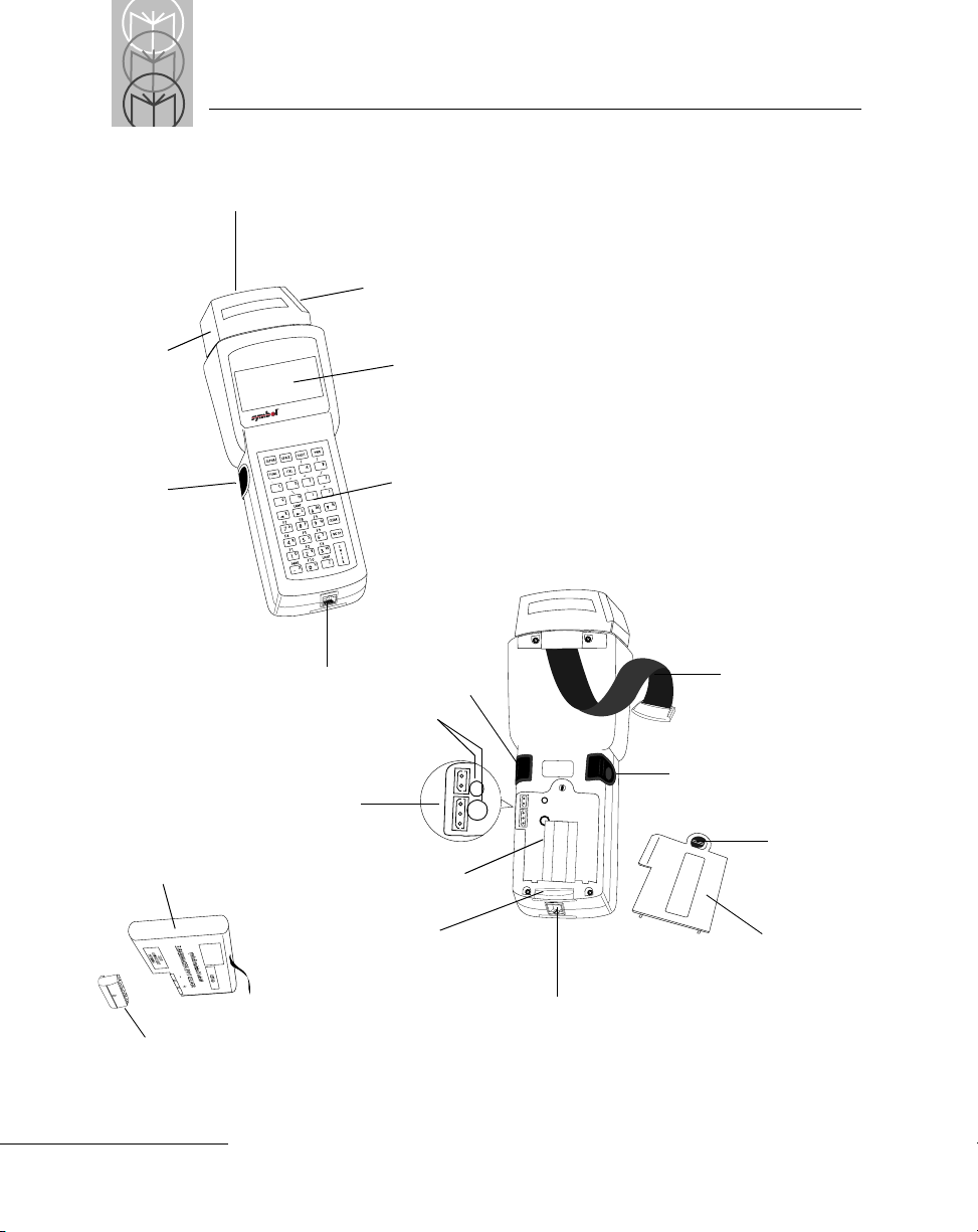
Parts of the Series 3100
Integrated Laser Scan Elemen t
Scanner Window
Scanner LED
Scanner
Trigg er
Rechargeable NiCd
Battery Pack
PDT 3100
Serial Port (RJ41)
Battery
Connector
Sockets
Removal
Strap
LCD Display Window
Keyboard
Scanner
Trigger
Holding Plugs
Battery Compartment
Handstrap
Latch
P
A
R
T
N
O
.
:
3
1
0
0
-
9
M
0
L
0
5
0
S
/
N
:
B
0
2
9
7
2
1
S
Y
M
B
O
L
T
E
C
H
,
I
N
C
.
Serial Port (RJ41)
Scanner
Trigger
Handstrap
Battery
Compartment
Latch
Battery
Compartment
Cover
1-4
Battery Adapter
Page 19
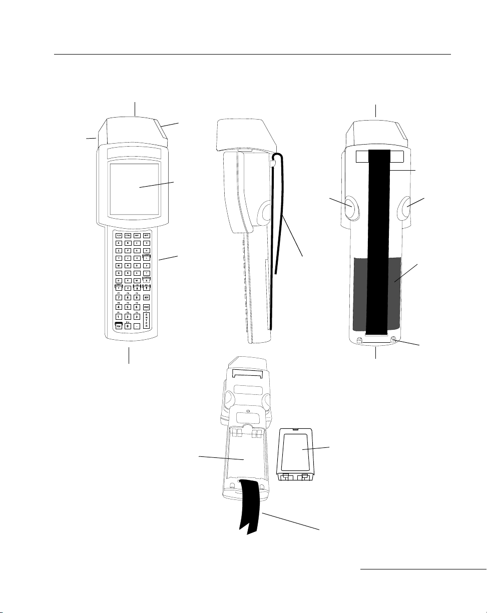
Parts of the Series 3500
The Series 3100/3500 System
Integrated Laser Scan Element
Scanner
LED
Serial Port (RJ41)
Scanner
Window
LCD Display
Window
Keyboard
Scanner
Trigger
Foldover
Strap with
Velcro
Attachment
Integrated Laser Scan Elemen t
Serial Port (RJ41)
Handstrap
Scanner
Trigger
Battery
Pack
Handstrap
Latch
Scanner
Trigger
Battery
Compartment
Scanner
Trigger
Battery
Pack
Handstrap
1-5
Page 20

Series 3100/3500 Product Reference Guide
Accessories
The following accessories are available for Series 3100/3500 terminals.
Battery Chargers
Series 31XX/35XX terminals use any one of the following:
• alkaline batteries (PPT 31XX only)
• rechargeable Nickel Cadmium (NiCd)
• rechargeable Nickel Metal Hydride (NiMH) battery packs.
NiCd and NiMH batteries are charged using one of the charging accessories listed
below.
Table 1-1. Battery Charging Accessories
Accessory Part Number Batteries Charged
Single-Slot Cradle CRD3100-100U (US version)
CRD3100-100 I (International)
Four-Slot Cradle CRD3100-400U (US version)
CRD3100-400 I (International)
Communications/Charger
Adapter
15 Volt Adapter
Universal Four-Slot Charger 3004-xxx KT-12596-01
UBC 1000 Charger UBC1000-xxxx All
3115-000
59915-00-00(US version)
All
All
KT-12596-01
KT-12596-02
Rechargeable batteries available from Symbol include:
For PDT 3100: 400 Mah (NiCd), 60 0 Mah (NiMH ).
For PDT 3500: 800 Mah (NiCd), 12 00 Mah (NiM H) .
1-6
Page 21

The Series 3100/3500 System
Scanners
PDT 31XX/35XX terminals may use either integrated or at tached scanners. A range of
available integrated scanners gives a range of possible scanning performance.
• standard range 1-D scanni ng
• long-range 1-D scanning
• standard range 1-D and 2-D scanning .
For terminals without an integrated scanner, the following attachable scanners are
available from Symbol:
• LS 2000 (1-D)
• LS 3000 (1-D)
• LS 4800 (1-D, 2-D)
• LS 9100 (1-D)
• LT 1700 (1-D)
• LP 1500 (wand, 1-D)
• PDF 1000 (1-D, 2-D)
Radio and Network Options
Spectrum One® Network
The PDT 3110 and 3510 i ncludes an in te rna l radio frequency transmitter/receiver for
use in a Symbol Spectrum One network.
The PDT 3124 includes a 2.4 GHz radio for use in Europe.
Spectrum24™ Network
The PDT 3140 and 3540 include an internal radio frequency transmitter/receiver for
use in a Symbol Spectrum24 network.
Flash Disk
The PDT 3140 and 3540 optionally include an additional 1 MB of non-volatile memory
or “flash disk” which is compatible with a standard DOS disk.
1-7
Page 22

Series 3100/3500 Product Reference Guide
Printers
The following printers can be used with Series 31XX/35XX terminals:
•Monarch Rascal
• Monarch Renegade
• ComTec 2-inch, 3-inch, 4-inch, and 3-inch receipt printers
Miscellaneous Other Accessories
Holsters are available for PDT 31XX and PDT 35XX terminals, and for tethered
scanners.
Before You Use the Terminal. . .
Install and Charge Battery
Prior to using the PDT 31XX/35XX for the first time, install the battery. If the terminal
uses a Nickel Cadmium (NiCd) or Nickel Metal Hydride (NiMH) rechargeable battery ,
charge the battery before use (refer to Chapter 6).
Load the Appropriate Software
What software you load and how you load it depends on several factors:
• If this unit is intended for use in batch applications (3100/3500) or in a Spectrum
One network environment (3110/3510), refer to Chapter 2 for information on
loading the software.
• If this unit is intended for use in a Spectrum24 network environment (3140/
3540), refer to Chapter 3 for general information on Spectrum24 and software
loading procedures.
1-8
Page 23

Chapter 2 Batch and Spectrum One Terminal Setup
Chapter Contents
Introduction . . . . . . . . . . . . . . . . . . . . . . . . . . . . . . . . . . . . . . . . . . . . . . . . . . . . . . . . . . . . . . . . . . . . . 2-3
Hardware Requirements. . . . . . . . . . . . . . . . . . . . . . . . . . . . . . . . . . . . . . . . . . . . . . . . . . . . . . . . . . . 2-4
Communications . . . . . . . . . . . . . . . . . . . . . . . . . . . . . . . . . . . . . . . . . . . . . . . . . . . . . . . . . . . . . 2-4
Hardware Setup. . . . . . . . . . . . . . . . . . . . . . . . . . . . . . . . . . . . . . . . . . . . . . . . . . . . . . . . . . . . . . 2-5
Connect Host and Cradle . . . . . . . . . . . . . . . . . . . . . . . . . . . . . . . . . . . . . . . . . . . . . . . . . . 2-5
Connect Host & 3115 CCA. . . . . . . . . . . . . . . . . . . . . . . . . . . . . . . . . . . . . . . . . . . . . . . . . 2-6
Loading the Program. . . . . . . . . . . . . . . . . . . . . . . . . . . . . . . . . . . . . . . . . . . . . . . . . . . . . . . . . . 2-7
Initiate Host Communications Software . . . . . . . . . . . . . . . . . . . . . . . . . . . . . . . . . . . . . 2-7
Initiate Terminal Communications . . . . . . . . . . . . . . . . . . . . . . . . . . . . . . . . . . . . . . . . . . 2-8
Starting Communications. . . . . . . . . . . . . . . . . . . . . . . . . . . . . . . . . . . . . . . . . . . . . . . . . 2-10
Ending Communications . . . . . . . . . . . . . . . . . . . . . . . . . . . . . . . . . . . . . . . . . . . . . . . . . 2-10
2-1
Page 24

Series 3100 / 3500 Product Reference Guide
2-2
Page 25

Batch and Spectrum One Terminal Setup
Introduction
Before using a Series 31XX/35XX terminal, perform the following procedures:
• install the battery (Refer to Chapter 6)
• charge the battery, if using a Nickel Cadmium (NiCd) or Nickel Metal Hydride
(NiMH) rechargeable battery (Refer to Chapter 6)
• Load the system files and application(s).
Programs are stored in the terminal’s nonvolatile memory (NVM), also called the
application EEPROM.
2-3
Page 26

Series 3100 / 3500 Product Reference Guide
Hardware Requirements
The following hardware is required to initialize a batch or Spectrum One radio
terminal:
•Terminal
• 1- or 4-Slot Cradle
OR
3115 Charging and Communications Adapter
• RS-232 Serial Null Modem Cable
• Power Supply
•Host PC
Communications
For terminals being used in a direct communications (batch) environment or a
Spectrum One network environment, applications are transferred from a host
computer to the terminal:
• over a communications line using a null modem connected to the cradle
OR
• through the communications/charger adapter.
The procedure uses the SENDHEX command on the host computer and the Program
Loader function (from Command Mode) on the terminal.
Note: For details on the SENDHEX command, refer to the
Series 3000 Application Programmer's Manual.
Other software may be used in place of SENDHEX.
2-4
Page 27
Hardware Setup
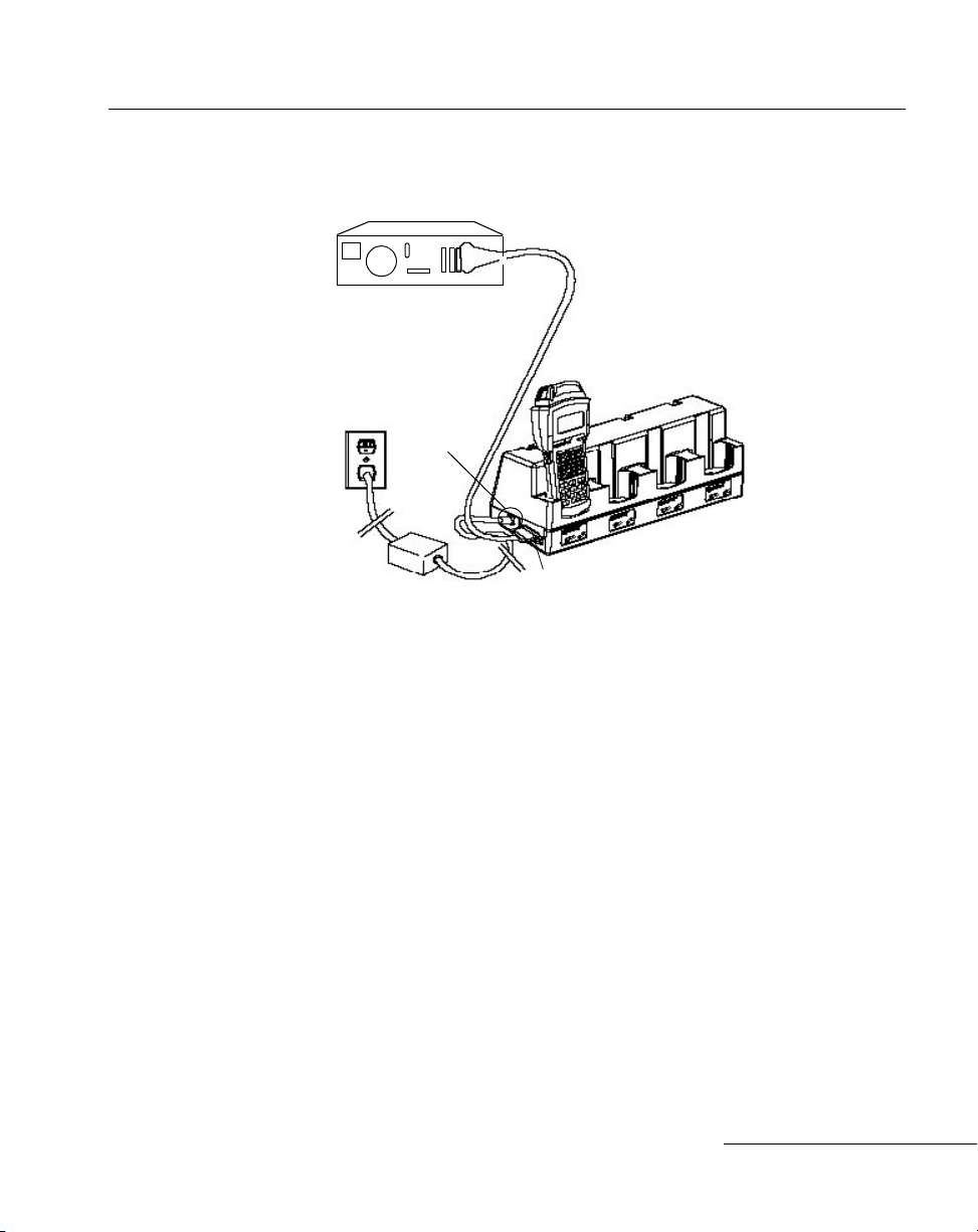
Connect Host and Cradle
Batch and Spectrum One Terminal Setup
Power Supply Cord
Host Computer
Power
Connector
Serial Null Mod em Cable
Comm Port
Figure 2-1. Cradle Setup for 3100/3110 and 3500/3510 Initialization
Note: The procedure for connecting 1- and 4-slot cra dles is the
same.
1. Plug the RS-232 serial cable’s connector into the cradle’s communication port.
2. Connect the other connector to the host computer’s serial (COMM) port.
3. Connect the power supply cord’s round plug to the power connector on the side
of the cradle (3165: power supply p/n 59915-00-00 for domestic use, 60507-00-00
for international use; 3166: power supply p/n 60153-00-00 for domestic use and
60174-00-00 for international use).
4. Connect the power supply’s AC plug to a standard electrical outlet.
The green and red indicators light for about 3 seconds, blink for 3 seconds, then go
out.
5. Place the terminal in the cradle. Verify that the terminal is OFF.
6. Go to Loading the Program.
2-5
Page 28
Series 3100 / 3500 Product Reference Guide
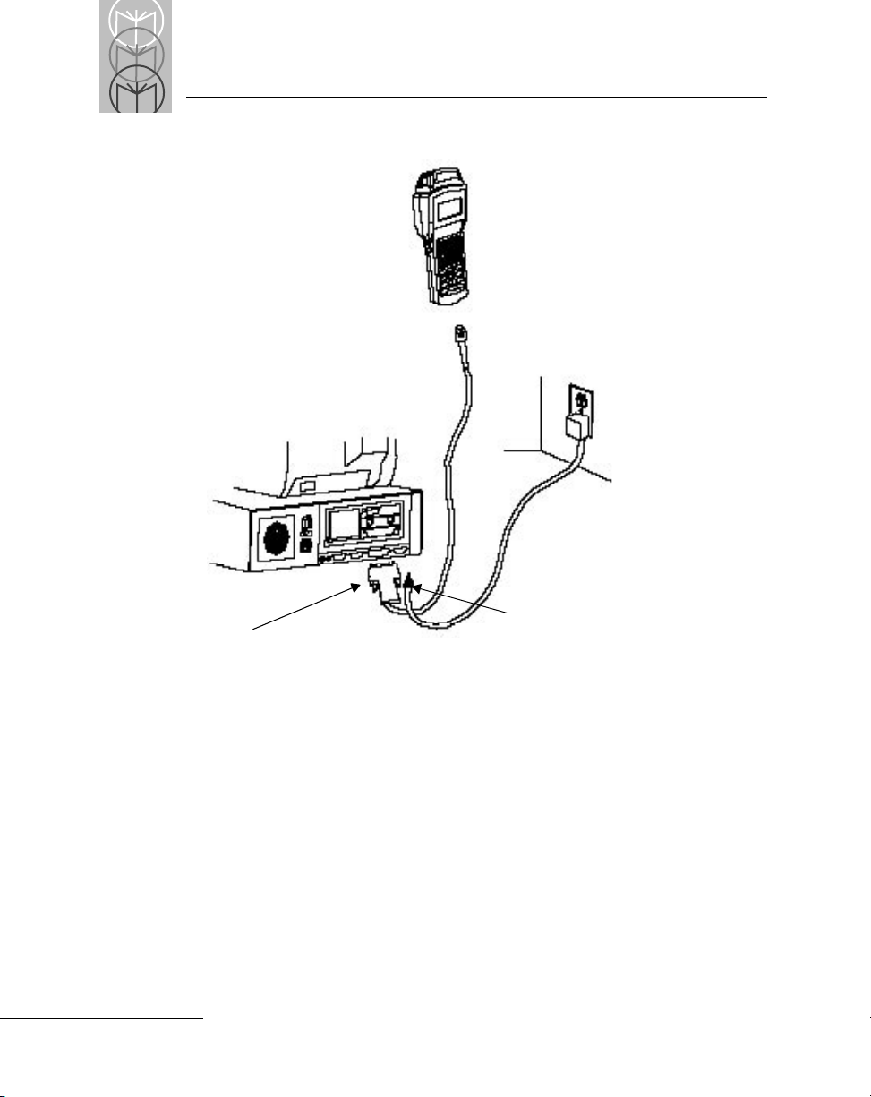
Connect Host, 3115 CCA
RJ41
3115 CCA
DB25
Power Input Jack
Figure 2-2. 3115 CCA Setup for 3100/3110 and 3500/3510 Initialization
1. Verify that the terminal is OFF.
2. Plug the 10-pin RJ-41 con nector in the terminal base.
3. Plug the DB25 connector into the host’s communications port.
4. Go to Loading the Program.
Caution
The 3115 CCA cable should be used to charge ONLY the KT12956-01 NiCd battery pack.
Note: It is not necessary to connect to a power supply for
communications.
2-6
Page 29

Batch and Spectrum One Terminal Setup
Loading the Program
Note: To cancel communications at any time during the
session, press CLEAR on the terminal. The session stops
immediately.
T o download the program, initiate the communications software on the host computer
and terminal as described in the f ollowing sections.
Note: Communication parameters specified on the host and
the terminal must match. These parameters typically
are:
38400 bps
7 bit data
Odd parity
Xon/Xoff flow control
Note: T o program the EEPROM, the terminal must be connected to
the host through a cradle or the 3115 CCA.
Initiate Host Communications Software
1. Power on the host computer.
2. Start the communication program.
3. Enter the SENDHEX command.
sendhex pgmname 38400 com2
where:
SENDHEX is the command.
pgmname is the application being loaded (.hex extension is
optional).
parameters Communications parameters follow the program
name. Parameters include baud rate,
communications port, data bits, parity, and flow
control. T o accept the default parameters, do not enter
a value.
In the example, the baud rate is set to 38400 bps and the communications port to
COM2. The default values are accepted for the remaining parameters.
2-7
Page 30

Series 3100 / 3500 Product Reference Guide
Note: Versions of SENDHEX earlier than 3.0 do not support
flow control. If you use an earlier version and encounter
communication errors, use a lower baud rate.
4. SENDHEX displays the prompt:
Press <Enter> to begin
communications.
5. Do NOT press <ENTER> yet. Before starting communications (refer to Starting
Communications), set up the terminal as directed in Initiate Terminal
Communications.
Initiate Terminal Communications
1. Boot the terminal to command mode. Refer to Chapter 4, Operating th e S e ri e s 3 100/
3500, for a list of the boot-to-command mode sequ e nce s.
The terminal displays the following:
COMMAND MODE
Select function
Self test
2. Scroll through Command Mode options using <UpArrow> or <DownArrow>
until “Program loader” is displayed. Press <ENTER>.
3. The terminal displays:
Program loader
WARNING: EEPROM
WILL BE ERASED
CONTINUE? <ENT>
Before loading the new application, erase the NVM’s original contents.
Note: To cancel this operation, press <CLEAR>.
4. Press <ENTER> to erase the EEPROM.
Wait while the EEPROM is erased. When complete, the program prompts for the
communications parameters.
2-8
Page 31

Batch and Spectrum One Terminal Setup
5. Baud Rate.The terminal displays:
Comm Parameters
Baud
4 9600
Scroll through the list using <UpArrow> or <DownArrow>. When the correct rate
is displayed (38400 is recommended), press <ENTER>.
6. Data Bits. The terminal displays:
Comm Parameters
Data Bits
7
Press <7> (recommended) or <8> to specify data bits, or scroll through the list
using <UpArrow> and <DownArrow>. Pr ess <ENTER> when the correct value is
displayed.
Note: If 8 data bits is selected, the program selects “No parity”
and skips the next step.
7. Parity. If 7 data bits is selected, the terminal displays:
Comm Parameters
Parity
Odd
Press the first letter of a parity option (Even, Odd, None, Space, or Mark), or scroll
using <UpArrow> and <DownArrow> and press <ENTER> when the correct
value is displayed.
8. Flow Control. The termina l displays:
Comm Parameters
Flow Control
None
Press the first letter of a flow control option (None, Xon/Xoff, or RTS/CTS), or
scroll using <UpArrow> or <DownArrow> and press <ENTER> when the corr ect
value is displayed.
9. The terminal ready to receive the program.
2-9
Page 32

Series 3100 / 3500 Product Reference Guide
Starting Communications
1. The terminal displays:
Comm Parameters
Start? <ENT>
2. Press <ENT> on the terminal.
3. Press <ENTER> on the host computer. SENDHEX begins transmitting the
program image. When communications are established, the terminal displays:
Program loader
Receiving: XXXX
During program loading, the display show s the program segment address being
transferred (XXXX).
4. When the transmission is complete, the terminal displays:
Program loader
Status 0000
A status of 0000 (all zeros) indicates a successful transfer. Other status values
indicate an error. These values are provided in Appendix C.
If you received an error , pr ess <Clear> on the terminal to return to the Command
Mode main menu.
Ending Communications
1. Press <Clear> on the terminal.
2. Power down the terminal.
3. Detach any cables connected to the terminal.
4. Reboot the terminal using the appropriate cold boot sequence described in
Chapter 4 in the section Booting a Terminal.
2-10
Page 33

Chapter 3 Spectrum24 RF Terminal Setup
Chapter Contents
Introduction . . . . . . . . . . . . . . . . . . . . . . . . . . . . . . . . . . . . . . . . . . . . . . . . . . . . . . . . . . . . . . . . . . . . . 3-3
Spectrum One Vs. Spectrum24 Terminals . . . . . . . . . . . . . . . . . . . . . . . . . . . . . . . . . . . . . . . . 3-3
The Flash Disk Option. . . . . . . . . . . . . . . . . . . . . . . . . . . . . . . . . . . . . . . . . . . . . . . . . . . . . . . . . 3-3
Standard Spectrum24 Installation. . . . . . . . . . . . . . . . . . . . . . . . . . . . . . . . . . . . . . . . . . . . . . . . . . . 3-4
Decision: Internet Addressing . . . . . . . . . . . . . . . . . . . . . . . . . . . . . . . . . . . . . . . . . . . . . . . . . . . . . . 3-4
Editing NET.CFG. . . . . . . . . . . . . . . . . . . . . . . . . . . . . . . . . . . . . . . . . . . . . . . . . . . . . . . . . . . . . . . . . 3-4
How Application Files Are Downloaded to the Terminal. . . . . . . . . . . . . . . . . . . . . . . . . . . . . . . 3-6
Loading the Software . . . . . . . . . . . . . . . . . . . . . . . . . . . . . . . . . . . . . . . . . . . . . . . . . . . . . . . . . . . . . 3-7
Hardware Required for Download. . . . . . . . . . . . . . . . . . . . . . . . . . . . . . . . . . . . . . . . . . . . . . 3-7
Hardware Setup. . . . . . . . . . . . . . . . . . . . . . . . . . . . . . . . . . . . . . . . . . . . . . . . . . . . . . . . . . . . . . 3-7
Verify Existence of Application Files . . . . . . . . . . . . . . . . . . . . . . . . . . . . . . . . . . . . . . . . . . . . 3-7
Download Over the Network: BOOTP (Default) . . . . . . . . . . . . . . . . . . . . . . . . . . . . . . . . . . . . . . 3-8
Initiate Network Connection . . . . . . . . . . . . . . . . . . . . . . . . . . . . . . . . . . . . . . . . . . . . . . . . . . . 3-8
Terminal Attempts to Associate with Access Point . . . . . . . . . . . . . . . . . . . . . . . . . . . . . . . . 3-9
Download Over the Network: DHCP. . . . . . . . . . . . . . . . . . . . . . . . . . . . . . . . . . . . . . . . . . . 3-12
Download Over the Network: Neither BOOTP or DHCP. . . . . . . . . . . . . . . . . . . . . . . . . . 3-13
3-1
Page 34

Series 3100 / 3500 Product Reference Guide
3-2
Page 35

Introduction to Spectrum24 RF Terminals
Introduction
Spectrum One Vs. Spectrum24 Terminals
In Spectrum One terminals, connectivity over the wireless network is effected through
a proprietary protocol. A terminal was dedicated to a specific application using a hex
image customized for the application (e.g., STEP or SVTP) that was loaded offline into
the terminal’s non-volatile memory (NVM). Any temporary files needed or created by
the application were placed on the RAM drive which used part of the program
execution space. The NVM appears to the application as a read-only disk drive (B:)
containing up to 256 Kbytes. The RAM drive (D:) is both readable and writable and is
sized by each application according to the applicati on ’s needs.
In Spectrum24 terminals, the wireless connectivity is accomplished using standard
communications protocols. Because they are standard, the protocols are generalized
and take up considerably more space on the terminal’s NVM. With less space available
in NVM for application files, Spectum24 terminals operate as diskless computing
workstations. The terminal’s NVM contains system files required to connect to and
download the application files from a network server and to provide network
diagnostics and configuration. The application files are downloa ded each time the
terminal is booted.
The Flash Disk Option
The 3140 and 3540 terminals optionally can contain an additional me gabyte of nonvolatile memory or flash disk. This extra memory is used to reduce the time and
resources required to load applications into the terminal and to offer the possibility of
running multiple applications from the same terminal.
The flash disk is accessed via a driver, FLASHDSK.SYS, which makes the flash disk
appear to a program as another disk drive (E:). The drive has characteristics of fast
reading but slow writing (e.g., for even the smallest files, the write process takes 3-4
seconds).
If your 3140/3540 termina l include s a flas h disk , yo u have options for setti ng the IP
address and downloading software that ar e not available on the stan dar d Spectrum24
terminals. For more information, refer to the Spectrum24 Flash Disk Addendum.
3-3
Page 36

Series 3100 / 3500 Product Reference Guide
Standard Spectrum24 Installation
A standard Spectrum24 installation consists of LSL, SLAODI.COM, TCP/IP, and
NET.CFG, and requires a BIOS versio n of 1. 09 or later.
The system software is factory-loaded in the terminals. The default files cover mos t
expected scenarios with minor changes, as detailed in this chapter. If your
requirements are more sophisticated, refer to the Spectrum24 Network Deve l opme n t Kit
documentation for more information on the Spectrum24 RF network, SLAODI.COM,
the Symbol-provided ODI driver, and the configuration file setups required for various
platforms.
Note: The installation for Spectrum24 terminals with flash disk
differs from a standard installation in the configuration file
setup and in the options for obtaining addresses and
downloading software. For more information, refer to the
Spectrum24 Flash Disk Addendum.
Decision: Internet Addressing
Each terminal requires a unique internet address, or IP address, allowing messages it
sends and receives to be correctly routed over networks conforming to the TCP/IP
protocol standards. These addresses can be administered and entered manually, or
administered and allocated by a server on the network. Two protocols are defined for
the IP address allocation on the network, BOOTP and DHCP. BOOTP is com monly
used in UNIX and OS/2; DHCP is the protocol for Windows NT servers.
By default, Symbol’s Series 3000 Spectrum24 terminals use the BOOTP protocol to
obtain an IP address. To allocate IP addresses manually or to use the DHCP protocol,
you must change the “boot” parameter in the [Spectrum24 Control] section of the
NET.CFG file that is loaded on the terminal. The format of the entries to NET.CFG is
discussed in the section Editing NET.CFG.
Editing NET.CFG
The terminal is controlled by entries in the NET.CFG file. After you decide how to
allocate IP addresses, edit NET.CFG to include the [Spectrum24 Control] section
necessary to set the IP addressing mode.
If you intend to make any changes to the terminal’s out-of-box default setup, you must
add the [Spectrum24 Control] section, which specifies parameters that apply to all
Spectrum24 uses, to NET.CFG.
3-4
Page 37

Introduction to Spectrum24 RF Terminals
[Spectrum24 Control]
This section includes the parameters for indicating the preferred method of obtaining
the IP address (over the air or manual), as defined in Table 3-1, Parameters in
[Spectrum24 Control] Section
.
Table 3-1. Parameters in [Spectrum24 Control] Section
Parameter Description
bootp By default, the terminal issues a BOOTP r equest on startup. If no Spect rum24
Control Section appears in NET.CFG, BOOTP is assumed.
noboot If this parameter is set to noboot, the terminal does not issue a BOOTP
request. The terminal IP address must be entered in the [TCPIP] section of
NET.CFG or manually using CFG24.
dhcp For a Window s NT envir onment, the terminal uses DHCP proto col to access
the network.
Note: The DHCP, BOOT, and NOBOOT modes are mutually exclusive.
Examples
Entries to a NET.CFG setup:
Spectrum24 control
DHCP
OR
Spectrum24 control
Noboot
If you change NET.CFG, the default HEX image must be rebuilt.
3-5
Page 38

Series 3100 / 3500 Product Reference Guide
How Application Files Are Downloaded to the Terminal
To download application files requires having a Trivial File Transfer Protocol (TFTP)
server on the network. If your site has more than 3-4 terminals, running a TFTP server
on a DOS-based machine is impractical because the operating system restricts you to
downloading to one terminal at a time. More sophisticated operating systems, e.g.,
UNIX, OS/2, or Windows NT , allow downloads to multiple terminals simultaneously .
The server is needed infrequently to load new applications or update existing
applications.
Downloading over the airwaves cannot be done until after the Internet addressing
decision is resolved, and any required edits to NET.CFG are entered because the IP
address is required to perform the file transfer.
3-6
Page 39

Introduction to Spectrum24 RF Terminals
Loading the Software
Hardware Required for Download
•Terminal
• Spectrum24 RF Network Boot Server
• Spectrum24 Ethernet Access Point
Note: No hardware connections (cradle or CCA) are required
to load the software over the Spectrum24 network. The
terminal must be within the coverage area of a
Spectrum24 Ethernet Access Point linked to a host
computer . The initialization software is factory
installed.
Hardware Setup
Refer to the Spectrum24 RF Network documentation listed in Related Publications in
About This Manual for information on the Spectrum24 network and equipment.
Verify Existence of Application Files
The application files to be downloaded to the terminal must be installed on a network
host before you initiate the network connection. For more information on setting up the
files on a host, refer to the Spectrum24 documentation listed in About This Manual.
3-7
Page 40

Series 3100 / 3500 Product Reference Guide
Download Over the Network: BOOTP (Default)
Initiate Network Connection
1. Cold boot the terminal.
Note: Verify that terminal is OFF before cold booting.
a. Press an d hol d <A+B+D>.
b. Press and release <PWR>.
c. Release <A+B+D>.
The terminal boots DR-DOS and loads the radio driver while displaying a series of
boot messages.
2. Enter a new Net Id, obtained from the Network Administrator, in the Configurator
(DFG24).
Note: This process should only be required on the first-time,
out-of-box network connection.
On first boot , the terminal automatically brings up the Configurator screen for
entering a new Net Id:
CONFIGURATOR 1.XX
View config params
Net Id
Subnet Mask
Default Router
Terminal IP Addr ess
Exit
↑
↑
, Clear, Enter
3. To enter the new Net Id:
a. Use the <UpArrow> and <DownArrow> to cursor to Net Id.
b. The default Net Id appears in hex format. Backspace over the existing value,
type a new value in the range 102-1FE (in hex, not case sensitive), and press
<ENTER>.
c. If you are using a BOOTP or DHCP server , cold boot the terminal and proceed
to the section, Terminal Attempts to Associate with Access Point.
4. If you are not using a BOOTP or DHCP server, enter the following parameters:
-Subnet Mask
3-8
Page 41

Introduction to Spectrum24 RF Terminals
- Default Router
- Termina l IP Addres s
and press <ENTER> after each entry.
Note: Your changes are saved in the nonvolatile area on the
radio card. The values just entered are not lost if you
reboot the terminal.
5. Select Exit from the Configurator Menu and press <ENTER> to exit the
Configurator to continue the connection process.
Terminal Attempts to Associate with Access Point
The terminal attempts to associate with an Access Point (AP) using the default Net Id.
If Terminal Association with AP Is Not Successful
If the terminal is unable to associate with the AP (the Net Id is wrong or forgotten), it
displays the message:
STAT24 Ver 1.XX
NOT Associated
for a few seconds. A second message follows:
Terminal cannot associate with AP. You’re
out of range or not configured. Ctrl+C to end
or other key to retry. Strike any key when ready.....
The terminal continues trying to connect until attempt is cancelled.
To cancel and set up a new Net Id (obtained from the Network Administrator):
1. Press <Ctrl+C> to end the attempt. The terminal displays the message:
Halt Batch process Y/N?
2. Type Y to exit to the DOS prompt (D:).
3. At the DOS prompt, type CFG24 and press <ENTER> to initiate the Configurator
and bring up the Configurator screen:
CONFIGURATOR 1.XX
View config params
Net Id
Subnet Mask
Default Router
3-9
Page 42

Series 3100 / 3500 Product Reference Guide
Terminal IP Address
Exit
↑
↑
, Clear, Enter
4. Use the <UpArrow> and <DownArrow> to cursor to Net Id.
5. The current Net Id appears in hex format. Backspace over the existing value, type
a new value in the range 102-1FE (in hex, not case sensitive), and press <ENTER>.
6. Power the terminal off.
7. Cold boot again.
8. The terminal attempts to associate with an AP.
If Terminal Association with AP Is Successful
If the association is successful, the terminal obtains an IP address and bootfile name,
displays the message:
BOOTP 1.XX
and begins downloading files from the server. As the download runs, the terminal
displays a series of application-defined messages. If the download is successful, the
terminal displays messages indicating success and the application logon screen. Begin
operating the terminal application.
Note: For flash disk terminals, if the terminal is not downloading
files over the air, the files are extracted from flash disk and
executed.
If Association Is Successful But Download Fails
The download may fail due to one of the following reasons:
Terminal Cannot Find BOOTP Server. If the terminal cannot find the BOOTP or
DHCP Server for download, it displays the message:
Cannot find Boot Server, time out
You have no boot server or it has problems
and returns to the DOS prompt. Contact the Symbol Sup port Center for assistance.
File Transfer Fails. If the file transfer fails, the terminal displays the message:
3-10
Page 43

Introduction to Spectrum24 RF Terminals
TFTP retry counter exceeded, Receive timeout.
Error <filename>
Ctrl-C to end or other key to retry.
where <filename> is the file being transferred that was not fully downloaded. The
terminal may be out of range of the AP and cannot find the files to transfer.
1. Press <Ctrl+C> to exit and request help from the Symbol Support Center.
OR
2. Press a key to retry the file transfer.
If File Transfer Succeeds
If the file transfer retry is successful, the terminal displays messages indicating success
and the application logon screen. Begin operating the terminal application.
If not, contact the Symbol Support Center for assistance.
3-11
Page 44

Series 3100 / 3500 Product Reference Guide
Download Over the Network: DHCP
To use the DHCP protocol requires editing NET.CFG and rebuilding the HEX file
before initiating the network connection.
1. Edit NET.CFG (refer to the section Editing NET.CFG for a more detailed
discussion). Add the section header and DHCP parameter line:
Spectrum24 Control
DHCP
2. Save the new NET.CFG on the network host in the \LWPnnn\KIT directory.
3. Working from the \LWPnnn\KIT directory, rebuild the HEX file. Use the
command:
USRCFG @LWPNFL
which builds a LWPNFL.HEX file in the KIT subdirectory.
4. Download the new HEX file. Refer to the Series 3000 ADK for instructions on
downloading a HEX file to the terminal.
5. Proceed with the network connection as described in the section Initi a te Network
Connection.
3-12
Page 45

Introduction to Spectrum24 RF Terminals
Download Over the Network: Neither BOOTP or DHCP
If a BOOTP or DHCP server is not used, the information these servers provide must be
obtained in other ways (i.e., the IP address is entered manually using CFG24).
1. Edit NET.CFG (refer to the section Editing NET.CFG for a more detailed
discussion). Add a control section and noboot parameter:
Spectrum24 control
Noboot
2. Proceed with saving the NET.CFG file, building and downloading a new HEX file,
and connecting to the network as described in Download Over the Network: DHCP.
3-13
Page 46

Series 3100 / 3500 Product Reference Guide
3-14
Page 47

Chapter 4 Operating the Series 3100/3500
Chapter Contents
Introduction . . . . . . . . . . . . . . . . . . . . . . . . . . . . . . . . . . . . . . . . . . . . . . . . . . . . . . . . . . . . . . . . . . . . . 4-3
Powering a Terminal On and Off . . . . . . . . . . . . . . . . . . . . . . . . . . . . . . . . . . . . . . . . . . . . . . . . . . . 4-4
Normal Power . . . . . . . . . . . . . . . . . . . . . . . . . . . . . . . . . . . . . . . . . . . . . . . . . . . . . . . . . . . . . . . 4-4
Automatic Power. . . . . . . . . . . . . . . . . . . . . . . . . . . . . . . . . . . . . . . . . . . . . . . . . . . . . . . . . . . . . 4-4
Forcing Power Off . . . . . . . . . . . . . . . . . . . . . . . . . . . . . . . . . . . . . . . . . . . . . . . . . . . . . . . . . . . . 4-4
Restarting After a Forced Power Off. . . . . . . . . . . . . . . . . . . . . . . . . . . . . . . . . . . . . . . . . . . . . 4-5
Booting a Terminal . . . . . . . . . . . . . . . . . . . . . . . . . . . . . . . . . . . . . . . . . . . . . . . . . . . . . . . . . . . . . . . 4-6
Warm Boot . . . . . . . . . . . . . . . . . . . . . . . . . . . . . . . . . . . . . . . . . . . . . . . . . . . . . . . . . . . . . . . . . . 4-6
Cold Boot. . . . . . . . . . . . . . . . . . . . . . . . . . . . . . . . . . . . . . . . . . . . . . . . . . . . . . . . . . . . . . . . . . . . 4-7
Cold-Boot Failure. . . . . . . . . . . . . . . . . . . . . . . . . . . . . . . . . . . . . . . . . . . . . . . . . . . . . . . . . . . . . 4-8
Boot to Command Mode. . . . . . . . . . . . . . . . . . . . . . . . . . . . . . . . . . . . . . . . . . . . . . . . . . . . . . . 4-9
Adjusting the Display . . . . . . . . . . . . . . . . . . . . . . . . . . . . . . . . . . . . . . . . . . . . . . . . . . . . . . . . . . . . 4-11
Backlighting . . . . . . . . . . . . . . . . . . . . . . . . . . . . . . . . . . . . . . . . . . . . . . . . . . . . . . . . . . . . . . . . 4-11
Display Contrast . . . . . . . . . . . . . . . . . . . . . . . . . . . . . . . . . . . . . . . . . . . . . . . . . . . . . . . . . . . . 4-11
The Series 3100/3500 Keyboard . . . . . . . . . . . . . . . . . . . . . . . . . . . . . . . . . . . . . . . . . . . . . . . . . . . 4-13
Using the Keyboard. . . . . . . . . . . . . . . . . . . . . . . . . . . . . . . . . . . . . . . . . . . . . . . . . . . . . . . . . . 4-13
Modifier Keys. . . . . . . . . . . . . . . . . . . . . . . . . . . . . . . . . . . . . . . . . . . . . . . . . . . . . . . . . . . . . . . 4-16
Key Descriptions . . . . . . . . . . . . . . . . . . . . . . . . . . . . . . . . . . . . . . . . . . . . . . . . . . . . . . . . . . . . 4-16
Scanning . . . . . . . . . . . . . . . . . . . . . . . . . . . . . . . . . . . . . . . . . . . . . . . . . . . . . . . . . . . . . . . . . . . . . . . 4-18
Integrated Laser Scanner . . . . . . . . . . . . . . . . . . . . . . . . . . . . . . . . . . . . . . . . . . . . . . . . . . . . . 4-19
Scanning 1-D Bar Codes . . . . . . . . . . . . . . . . . . . . . . . . . . . . . . . . . . . . . . . . . . . . . . . . . . . . . . 4-20
Scanning Considerations . . . . . . . . . . . . . . . . . . . . . . . . . . . . . . . . . . . . . . . . . . . . . . . . . . . . . 4-21
Standard and Long Range 1-D Decode Zones. . . . . . . . . . . . . . . . . . . . . . . . . . . . . . . . . . . . 4-23
Note on IEC825/EN60825 Class 1. . . . . . . . . . . . . . . . . . . . . . . . . . . . . . . . . . . . . . . . . . . . . . 4-24
Scanning PDF417 Bar Codes . . . . . . . . . . . . . . . . . . . . . . . . . . . . . . . . . . . . . . . . . . . . . . . . . . 4-25
To Scan PDF417 Bar Codes. . . . . . . . . . . . . . . . . . . . . . . . . . . . . . . . . . . . . . . . . . . . . . . . . . . . 4-26
Attaching a Scanner or Wand . . . . . . . . . . . . . . . . . . . . . . . . . . . . . . . . . . . . . . . . . . . . . . . . . 4-30
Communications . . . . . . . . . . . . . . . . . . . . . . . . . . . . . . . . . . . . . . . . . . . . . . . . . . . . . . . . . . . . . . . . 4-31
With a PC . . . . . . . . . . . . . . . . . . . . . . . . . . . . . . . . . . . . . . . . . . . . . . . . . . . . . . . . . . . . . . . . . . 4-31
With a Printer . . . . . . . . . . . . . . . . . . . . . . . . . . . . . . . . . . . . . . . . . . . . . . . . . . . . . . . . . . . . . . . 4-32
Connecting the Internal Modem . . . . . . . . . . . . . . . . . . . . . . . . . . . . . . . . . . . . . . . . . . . . . . . . . . . 4-35
4-1
Page 48

Series 3100/3500 Product Reference Guide
Connecting to the Telephone Network4-36
4-2
Page 49

Operating the Series 3100/3500
Introduction
This chapter describes how to operate a Series 3100/3500 termin al, including:
• Powering the terminal on/off
• Booting the terminal
• Adjusting the display
• Using the keyboard
• Entering data via the integrated scanner or attached scanners
• Communicatin g with other devices using one of the following options:
- Connecting the terminal to a PC, printer, or modem using the 3115
Communication/Charging Adapter
- Connecting the terminal to a printer usi ng the passive cable
- C onnecting the direct connect and acoustic modems.
4-3
Page 50

Series 3100/3500 Product Reference Guide
P owering a Terminal On and Off
Because the terminal is battery powered, it is important to save power whenever
possible. Y ou can minimize power loss and increase battery life by turning the terminal
off when data is not being entered.
While the terminal’s processing and display are off, programs or data in the system's
memory are retained. Before the terminal powers up, it checks the batteries for enough
power to ensure reliable operation and data storage. Power-up restores the display , and
processing continues from where it was before power-down.
Powering the terminal on does not boot the system or initialize either the program or
data. For more information on initialization, refer to Chapter 2.
Normal Power
Note: If the terminal uses a NiCd or NiMH battery for power,
charge the battery before use!
To power the terminal on or off, press <PWR>.
Automatic Power
Depending on the application, a number of other events may turn a terminal on or off.
Some of these are:
Power On
• The system powers on when a key other than <PWR> is pressed.
• The system powers on when a scanner trigger is pressed.
• The program powers on the system at a preset time to perform unattended
operations, such as an overnight communications session.
• The program powers on the system in response to a modem ring or an RS-232
device connected to the RJ connector.
Power Off
If not used for a specific period of time, as determined by the application, the system
powers off automatically to conserve power.
Forcing Power Off
If a terminal freezes in the middle of operation, pres sing <PWR> does not power it off.
You can force the system to power off, which reduces the drain on the batteries until
you can download any collected data to the host system.
4-4
Page 51

Operating the Series 3100/3500
To force the system to power off, press and hold <PWR> for 15 seconds.
Since the ter mina l is still f ro zen at this tim e, t urni ng th e pow er bac k on does no t solv e
the problem. To recover the data held in memory, perform a W arm Boot (refer to Booting
a Terminal).
Restarting After a Forced Power Off
If an operator is forced to power down a terminal because of defective software, the
System Administrator should restart the system using the warm or cold boot
procedures in the following section.
Note: Do not use the power key to restart if the terminal was
forced off due to defective system or application
program software in NVM. Pressing <PWR> only
causes the program to resume where it left off, trying to
perform the same unsuccessful operation.
4-5
Page 52

Series 3100/3500 Product Reference Guide
Booting a Terminal
Powering the terminal on does not boot the system or initialize the program or data. T o
initialize the terminal, perform either a warm or cold boot.
Warm Boot
A warm boot resets the operating system while preserving the program and data on
the RAM disk. This process is similar to pressing the <Ctrl+Alt+Del> keys on a PC,
except that it does not clear the system's memory. To perform a warm boot:
21-Key Terminal:
1. Power off the terminal.
2. Press and hold <DownArrow> and <.>.
3. Press and release <I/O>.
4. Release <DownArrow> and <.>.
35-Key Terminal:
1. Power off the terminal.
2. Press and hold </> and <+>.
3. Press and release <PWR>.
4. Release </> and <+>.
46-Key Terminal:
1. Power off the terminal.
2. Press and hold <4> and <5>.
3. Press and release <PWR>.
4. Release <4> and <5>.
47-Key Terminal:
1. Power off the terminal.
2. Press and hold <4> and <5>.
3. Press and release <PWR>.
4. Release <4> and <5>.
4-6
Page 53

Operating the Series 3100/3500
The terminal displays a copyright message, RAM size, expanded memory RAM size,
etc., depending on the system's configuration.
Note: If the batteries are replaced and the supercap is
discharged, the terminal cold boots.
Cold Boot
A cold boot fully resets the system and clears memory, including the RAM disk. Any
programs and data stored i n memory or on the RAM disk are deleted. Nonvolatile
memory (NVM — the Application EEPROM) is not affected.
Caution
This procedure erases all data and pr ograms r esiding in dynamic memory and RAM Disk. All contents of the RAM disk are lost.
To perform a cold boot:
21-Key Terminal:
1. Power off the terminal.
2. Press and hold <UpArrow>, <4>, and <ENTER>.
3. Press and release <I/O>.
4. Release <UpArrow>, <4>, and <ENTER>.
35-Key Terminal:
1. Power off the terminal.
2. Press and hold <Space>, <Func>, and <UpArrow>.
3. Press and release <PWR>.
4. Release <Space>, <Func>, and <UpArrow>.
4-7
Page 54

Series 3100/3500 Product Reference Guide
46-Key Terminal:
1. Power off the terminal.
2. Press and hold <A>, <B>, and <D>.
3. Press and release <PWR>.
4. Release <A>, <B>, and <D>.
47-Key Terminal
1. Power off the terminal.
2. Press and hold <A>, <B>, and <D>.
3. Press and release <PWR>.
4. Release <A>, <B>, and <D>.
The terminal displays a copyright message, amount of RAM, and expanded memory.
Other messages are displayed as well, depending on the system configuration.
Cold-Boot Failure
During a cold boot, the system briefly displays a status line for each driver as it loads
in the format:
0: Driver #.##
The line shows a status value, usually 0, followed by the name and version number of
the driver . If the sy stem halts at one of these lines and displays a status value other than
0, the displayed device driver failed to load properly.
If such a failure occurs, the terminal may need to be cold booted. If this does not solve
the problem, call Symbol Support Center.
More troubleshooting information is found in the publications listed at the beginning
of this manual.
4-8
Page 55

Operating the Series 3100/3500
Boot to Command Mode
Command Mode provides functions for:
• Running the Self-Test program to verify that the hardware is operating properly
(refer to Chapter 5)
• Performing a Memory Transfer to upload data from a terminal to the host system
(refer to Chapter 5)
• Performing a Progra m Dow nload to transfer an appli c ation program from the
host system to a terminal (refer to Loading the Program in Chapter 2).
21-Key Terminal:
1. Power the terminal off.
2. Press and hold <send> and <9>.
3. Press and release <I/O>.
4. Release <send> and <9>.
35-Key Terminal:
1. Power the terminal off.
2. Press and hold <BackSpace> and <Shift>.
3. Press and release <PWR>.
4. Release <BackSpace> and <Shift>.
46-Key Terminal:
1. Power the terminal off
2. Press and hold <F> and <I>.
3. Press and release <PWR>.
4. Release <F> and <I>.
4-9
Page 56

Series 3100/3500 Product Reference Guide
47-Key Terminal
1. Power the terminal off
2. Press and hold <F> and <I>.
3. Press and release <PWR>.
4. Release <F> and <I>.
4-10
Page 57

Operating the Series 3100/3500
Adjusting the Display
Backlighting
The terminal’s backlight illumin ates the display in dimly lit areas.
Note: Use of backlighting can significantly reduce battery life.
To turn the backlight on or off, press the following keys in sequence:
21-Key Keyboar d:
<Func> then <RightArrow>
35-Key Keyboar d:
<Func> then <RightArrow>
46-Key Keyboar d:
<Func> then <L>
47-Key Keyboar d:
<Func> then <L>
The backlight also turns off when a terminal is powered off or when a timeout set by
the application occurs.
Display Contrast
The LCD display contrast is adjustable, making the display more readable in different
lighting conditions, at various temperatures, with different attachments, and at other
viewing angles.
To increase contrast (darken) by one step, press the following keys in sequence:
21-Key Keyboar d:
<Fn> then <DownArrow>
35-Key Keyboar d:
<Func> then <X>
46-Key Keyboar d:
<Func> then <X>
4-11
Page 58

Series 3100/3500 Product Reference Guide
47-Key Keyboar d:
<Func> then <X>
To decrea se contrast (lighten) by one step, pr ess:
21-Key Keyboar d:
<Fn> then <UpArrow>
35-Key Keyboar d:
<Func> then <Z>
46-Key Keyboar d:
<Func> then <Y>
47-Key Keyboar d:
<Func> then <Y>
4-12
Page 59

Operating the Series 3100/3500
The Series 3100/3500 Keyboard
The keyboard is used for ent e r i ng data and issuing commands to the term inal. Figure
4-1 illustrates the standard 35-key keyboard, while Figure 4-2 presents the standard
PDT 3500 47-key keyboard. For the other Series 31XX/35XX keyboards, refer to
Appendix B.
The keys on the keyboard are distinguished as modifier keys and character keys.
Because terminal keyboards have fewer keys than PC keyboards, each character key
can produce more than the usual one or two characters. Th e four modifier keys, Shift,
Alpha, Ctrl, and Func, used individually or in combination, determine which
character or special function the character keys produce.
Using the Keyboard
Except for during boot operations, the terminal expects the operator to press keys one
at a time. If ERR3000 is load ed, and if two or mor e keys are pr essed simult aneously, the
system indicates a Double Key error.
The keyboard also has an optionally configurable auto-repeat function. If the
application allows, a character repeats as long as the key is held down. If the key is
pressed immediately following a modifier key, the modifier sequence affects only the
first occurrence of the character key.
4-13
Page 60

Series 3100/3500 Product Reference Guide
ALPHA SPACE SHIFT PWR
[]
FUNC CTRL
'
C
,
GHI
K
F7 F8 F9
O
78 9
F4 F5 F6
RST
4
F1 F2 F3
U
1
DARK LIGHT
X
-
=
D
\
LAMP
L
PQ
56
V
2
F10
YZ
0
A B
*
E
;+
MN
W
3
.
/
F
J
CLEAR
BK SP
E
N
T
E
R
4-14
Figure 4-1. Series 3100 Standard 35-Key Keyboard
Page 61

Operating the Series 3100/3500
Figure 4-2. Series 3500 Standard 47-Key Keyboard
4-15
Page 62

Series 3100/3500 Product Reference Guide
Modifier Keys
The <Shift>, <Alpha>, <Func>, and <Ctrl> keys are modifier keys. When pressed
individually or in certain combination s, these keys change the keyboard state and
possibly the character produced by the character key subsequently pressed.
For example:
• Pressing <Alpha> causes the numeric keys to produce letters. (Lower case letters
are not available on the 35-key terminal, but they are available on the 46-key
terminal.)
• Pressing <Func> followed by <Ctrl> produces Alt characters, with the same
effect as pressing the Alt key on a PC.
• Pressing <Func> and a scanner trigger enables that trigger for scanning. (Refer
to the section Scanning for more information.)
• The opposite trigger is another Alpha key (Alpha Shift), producing capital letters.
It is active only when held down.
•The <Alpha> key on the keyboard affects all succeeding character keys until
<Alpha> is pressed again. The other modifier keys af fect only the next character
key.
Refer to Appendix B for the characters and operations produced by pressing a
sequence of modifier keys on the standard term inal keyboards. These key assignments
can be changed by an application. Refer to your application documentation for any
special key assignments.
Cancelling a Modifier Key
To cancel the effect of a modifier key, press it again.
Keyboard State
The cursor’s shape indicates the current keyboard state, unless changed by the
application. The standard cursor shapes are shown in Table 6-4, Cursor Indicators.
Key Descriptions
Most of the keys are self-explanatory . Letter keys pr oduce letters, number keys produce
numbers. Keys that perform special functions are described in T a ble 4-1, Special Keys.
4-16
Page 63

Operating the Series 3100/3500
Table 4-1. Special Keys
Key Name Description
Shift Changes letter and number keys to punct uat ion marks and
symbols (e.g., pressing <Shift + 5> on a 35-key keyboard
produces a % sign).
Alpha Shifts the keyboard to produce alphabetic characters. Uppercase
only on 35-key; upper and lowercase available on the 46-key
terminal.
Alpha Shift
(trigger key)
Func Function key. Invokes special keyboard functions.
Ctrl Control key. Generates control characters.
Enter
Lamp Turns on t he backlight
Clear
(Escape)
Dark Following Func, darkens the display (increases contrast).
Light Following Func, lightens the display (reduces contrast).
Trigger keys Activates the scanner. Selectable by the operator. The
Shifts the keyboard to produce alphabetic characters when held
down continuously. Selectable by the operator. The
corresponding key on the other side key becomes the active
scanner trigger.
U
sually pressed after typing data or a command.
Depending on the application, completely or partia lly esc apes
from an application lev el or scr een, or clears data entered in a
field.
corresponding key on the oth er side key becomes the Alpha Shift.
4-17
Page 64

Series 3100/3500 Product Reference Guide
Scanning
The 3100/3500 terminals support several scanning devices, including:
• Integrated scanning elements, such as:
- 1-D Standard and Long Range Scanning Elements
- 1-D and 2-D Scanning Element
• Tethered scanners, such as:
- LS 2000
- LS 3000
- LS 4800
- LS 9100
- LT 1700
- LP 1500
If you use a tethered scanner with the terminal, follow its pertinent instructions for
installation and operation.
Note: Before scanning can actually occur , the application must
implement routines to support bar code scanning. For information
on scanning ap plication s and on pro gramming the scanner , refer to
the Series 3000 Applic ation Development Ki t.
4-18
Page 65

Operating the Series 3100/3500
Integrated Laser Scanner
Settin g th e Trigger
The integrated scanner has a unique trigger that the operator can configure. To use the
integrated laser scanner:
1. Power on the system and scanner by pressing <PWR> or the scanner trigger.
2. Lift up and turn the the scan element on the top of the terminal to the preferred
orientation for scanning (refer to Figure 4-3). The scan head turns only toward the
back of the terminal.
Figure 4-3. Positioning the Scanner
3. Lock the scan head in position, facing the side of the terminal.
4. To select the trigger, press the <FUNC> key and the trigger you are most
comfortable using. The other trigger defaults to an ALPHA shift key. Depending
on the application, the terminal may beep to indica te a trigger is selected.
4-19
Page 66

Series 3100/3500 Product Reference Guide
Scanning 1-D Bar Codes
If using a tethered scanner, follows its instructions for operation. If you use an
integrated scanner, follow this procedure.
1. Aim the scanning element at the bar code and press the selected trigger.
2. Adjust the aim so that the thin, red laser beam covers the entire length of the bar
code.
Wrong
Optimal scanning distance varies with bar code density and scanner optics, but
most combinations work within 4 to 10 inches. Generally:
• The larger the symbol, the farther away you should hold the scanner.
• Move the scanner closer for symbols with bars that are close together.
Simple practice quickly shows what distances to work within.
3. If the decode is successful, the s creen displays the code and the gr een LE D flashes.
The terminal may also beep.
Note: The procedure for your scanner may dif fer from the one
listed above. Scanner use depends on the application.
Right
4-20
Page 67

Operating the Series 3100/3500
Scanning Considerations
Usually, sca nning is a simple matter of aim, scan, and decode, and a few quick trial
efforts master it simply and intuitively. However, two important considerations can
optimize any scanning technique — angle and range.
Angle
Scanning angle is important for promoting quick decodes. When laser beams reflect
directly back into the scanner from the bar code, this specular reflection can actually
“blind” the scanner.
To avoid this, scan the bar code so that the beam does not bounce directly back. But
don’t scan at too oblique an angle; the scanner needs to collect scattered reflections
from the scan to make a successful decode. Practice quickly shows what tolerances to work
within.
Tilt Back At Slight Angle
1. Specular reflection:
reflected beam interferes.
Figure 4-4. Scanning Angle and Specular Reflection
Bar Code
2. No specular reflection.
Decode ca n o c cur .
Bar Code
4-21
Page 68

Series 3100/3500 Product Reference Guide
Range
Any scanning device decodes well over a particular working range — minimum and
maximum distances from the bar code. This range varies according to bar code density
and scanning device optics.
Scanning with in range b rings quic k and consta nt decodes; scanning to o close or too far
away prevents decodes. You need to find the right working range for the bar codes you
are scanning. The best general advice is:
• The larger the symbol, the farther away you should hold the scanner.
• Move the scanner closer for symbols with bars that are close together.
•Start scanning at a distance from the bar code — not from direct contact. If the bar
code does not readily decode, move the scanner in closer.
However, the situation is complicated by the availability of multiple integrated
scanning elements, some with specialized capabilities like long-range or 2- D decode
capability. The best way to specify appropriate working range per bar code density is
through a chart called a decode zone for each scan module. A decode zone simply plots
working range as a function of minimum element widths of bar code symbols.
Decode zones for available integrated 1-D scan elements follow:
4-22
Page 69

Operating the Series 3100/3500
Standard and Long Range 1-D Decode Zones
NOTE: Typical performance at 68o F ( 20o C) on high quality symbols.
11.7
29.75
Integrated
Scanner
Depth of
Field
in Inches
Integrated
Scanner
Depth of
Field
in Inches
5 Mil
7.5 Mil
20 Mil Minimum Element Width
40 Mil Minimum Element Width
55 Mil Minimum Element Width
2 4 6 8 100
12 141 16 18 20 22
26 32 34
302824
12.7 25.40 38.1 50.8 63.5 86.476.2
Depth of field as a function of minimum element width.
Figure 4-5. Decode Zone: Standard Range
NOTE: Typical performance at 68o F ( 20o C) on high quality symbols.
10 Mil
15 Mil. Min
20 Mil Minimum Element Width
40 Mil Minimum Element Width
55 Mil Minimum Element Width
5
0
5
11.7
In.
In.
Cm.
11.5
5
0
5
11.5
In.
12.7
0
12.7
29.75
Cm.
29.2
12.7
0
12.7
29.2
Cm.
Width of Field in Inches / Centimeters
Width of Field in Inches / Ce ntimeters
10
5
15 200 25
30
35 40 45 60
50
25.4 50.80 76.2 101.6 127 177.8152.4
Depth of field as a function of minimum element width.
Figure 4-6. Decode Zone: Long Range
55
65 70
In.
Cm.
4-23
Page 70

Series 3100/3500 Product Reference Guide
Note on IEC825/EN60825 Class 1
IEC825/EN60825 Cla ss 1 is an inter national laser s afety standar d that limi ts the amount
of energy emitted by the laser over a period of time. IEC825/EN60825 Class 1 limits the
duration of laser scan ner on-time, using an emission accumulator mechanism.
To confo rm to IEC825 /EN60825 Class 1 st andar ds, the las er cannot be on for mor e than
60 seconds in a 1000-secon d time period. The term inal accumulat es scan time whi le it is
scanning bar codes, up to the maximum 60 se con d s.
When it runs out of available scan time, the terminal emits a long, low-tone beep. When
2 seconds of scan time become available, the system emits another long, high-frequency
beep. Refer to the Series 3000 Application Programmer’s Guide for more information.
4-24
Page 71

Operating the Series 3100/3500
Scanning PDF417 Bar Codes
Smart Raster Capability
All integrated 1-D/PDF417 scan elements may be programmed for “Smart Raster”
capability, which causes the scanner to emit a raster pattern dynamically optimized to
the particular PDF417 bar code’s shape. To increase scanning efficiency and optimize
decode time, the scanner determines the geometry of the bar code and opens at a rate
and size optimal for decoding that bar code.
In normal “Smart Raster” operation, a trigger pull causes a slab raster pattern to
appear. If the target is a 1-D bar code, the pattern never gets beyond a slab raster. But
if the target bar code is PDF417, the scanning patterns open up to a full, optimized
raster pattern as soon as the scanner is pr operly aligned over the bar code, as shown in
Figure 4-7.
Aiming “D ot ” Pa tt e rn
Aiming “Slab” Raster Pattern
Open Raster Pattern
Y-Axi s
Horizontal Displacement (X - Axis)
Figure 4-7.
For best operation in smart raster mode, keep the scan pattern as parallel to the
symbol’s rows as possible, keep the scanner as still as possible, and hold the scanner at
an angle which does not give specular reflection (refer to the earlier section Angle).
Likewise, the symbol should be in good cond ition.
1-D/PDF417 Scan Element
Aiming and Scanning Patterns
Y-Axis
4-25
Page 72

Series 3100/3500 Product Reference Guide
1-D/PDF417 Scanning Mode Options
There are three main scanning options: aiming with a dot pattern, scanning with a slab
raster pattern, or always raster.
Aiming Dot Option.
for a fixed interval. This dot easily can be seen in outdoor or high ambient light
environments. A slab raster pattern or an open raster pattern appears next, depending
on the pr ogrammed sca nning option . There ar e two pr ogrammable timeout pe riods for
this option — normal and extended.
A trigger pull creates the single dot aiming pattern, which lasts
Slab Raster Option. A trigger pull creates the slab raster pattern. If the target
is a 1-D bar code, the pattern never gets beyond a slab raster. But if the target
bar code is PDF417, the pattern opens up to an optimized raster pattern as soon
as the scanner is properly aligned over the bar code.
Always Raster. When programmed to this option, the 1-D/PDF417 scan element
directly opens to a full raster pattern whenever the trigger is pulled.
To Scan PDF417 Bar Codes
Make sure that the scanner has been programmed for a slab raster aiming pattern and
smart raster mode.
1. Aim the scanner at the symbol. T ry to keep the nose of the scanner parallel with the
symbol’s rows.
2. Ensure the symbol you want to scan is within the scanning range(refer to the 1-D/
PDF417 decode zones in Figure 4-5 and Figure 4-6). Then pull the trigger to scan.
The scan pattern first covers the symbol horizontally.
Figure 4-8. Slab Raster Pattern on a PDF417 Bar Code
Make sure the scan pattern extends at least three-quarters of an inch beyond the
edges of the bar code (refer to Figure 4-8).
If the pattern is parallel to the symbol’s rows, the pattern spreads vertically to
cover the symbol. If the pattern does not cover the top and bottom of the symbol,
pull the scanner back until it does (refer to Figure 4-9).
4-26
Page 73

Operating the Series 3100/3500
3/4”
3/4”
Figure 4-9. Scanning Pattern Spreading Over PDF417 Bar Code
The scanner has successfully decoded the symbol when:
•The green LED lights.
•You hear a short, high tone beep.
Scan the Entire Bar Code Symbol
• The larger the symbol, the farther away you should hold the scanner to permit
the raster pattern to cover the symbol (but not more than 8 inches). Refer to 1-D/
PDF417 Scan Element Decode Zon es.
• Hold the scanner close for denser symbols (not less than 2 inches).
• In all cases, make sure the scan pattern extends at least 3/4 inch beyond each edge
of the bar code.
4-27
Page 74

Series 3100/3500 Product Reference Guide
• The PDF417 bar code symbol has multiple rows, but the raster pattern also has
multiple scanning rows. For this reason, do three basic things as you scan (refer
to Figure 4-10):
1. Center the aiming pattern on the bar code, as illustrated before.
2. Keep the pattern in the same horizontal plane as the bar code.
3/4” 3/4”
Figure 4-10. Orienting Scanning Pattern On PDF417 Bar Code
3. If the vertical scan pattern is not high enough to cover a “tall” PDF417
symbol, it may be necessary to move the scanner slowly down toward the
bottom of the symbol, keeping the beam horizontal to the rows, and then
slowly back upward toward the top (refer to Figure 4-11).
Figure 4-11. Moving Scan Pattern Upward and Downward on “Tall” PDF Symbol
• The scan beam does not have to be perfectly parallel with the top and bottom of
the symbol (up to a 4
o
tilt will work).
4-28
Page 75

1-D/PDF417 Scan Element Decode Zones
NOTE: Typical performance at 68o F ( 20o C) on high quality symbols.
Integrated
Scanner
Depth of
Field
in Inches
6 Mil
7.5 Mil
20 Mil Min. Element Width
40 Mil Minimum Element Width
55 Mil Minimum Element Width
Operating the Series 3100/3500
10
25.4
8
6
5
12.7
4
2
0
0
2
4
5
12.7
6
8
10
25.4
Cm.
In.
Width of Field in Inches / Centimeters
2 4 6 8 100 12 141 16 18 20 22 302824
12.7 25.40 38.1 50.8 63.5 76.2
Depth of field as a function of minimum element width.
26 32
In.
Cm.
Figure 4-12. 1-D/PDF417 Scan Element 1-D Decode Zone
NOTE: Typical performance at 68o F ( 20o C) on high quality symbols.
Integrated
Scanner
Depth of
Field
in Inches
Depth of field as a function of minimum element width.
Y -module dimension = 3 X.
6.6 Mil
10 Mil Minimum Element Width
15 Mil Minimum Element Width
2 4 6 80
101
12
14
5.1 10.1 15.2 20.30 25.42.5 30.5 35.6
2.5
2.5
In.
In.
Cm.
Figure 4-13. 1-D/PDF417 Scan Element PDF417 Decode Zone
5
12.7
6.4
0
0
6.4
12.7
5
Cm.
Width of Field in Inches / Centimeters
4-29
Page 76

Series 3100/3500 Product Reference Guide
Figure 4-14. Attaching/Using a Scanner
Attaching a Scanner or Wand
To attach a scanner or wand to a terminal:
1. Power the system off.
2. Remove the end cap from the top of the terminal.
3. Plug the scanner into the top of the terminal (refer to Figure 4-14).
4. Power the terminal on or press the scan trigger to power the terminal on.
5. To use the scanner or wand, refer to the user documentation provided.
Note: The <Enter> key is often the default "soft trigger." Applications
can designate another key as the "soft trigger." Refer to the
Series 3000 Application Programmer's Reference Manual for more
information on the STG3000.EXE program.
4-30
Page 77

Operating the Series 3100/3500
Communications
With a PC
3115 Communications/Charger Adapter
An optional communications/ charger adapter (CCA) is available for communicating
with a host PC when a cradle is not available.
Note: It is not necessary to connect the terminal to a power
source for communications.
To connect the 31XX/35XX to a PC using the 3115 CCA:
1. Plug the 10-pin RJ-41 connector into the base of a Series 31XX/35XX terminal (refer
to Figure 4-15).
2. Plug the DB-25 connector into the host’s communications port.
3. Start the communications program.
PDT 3100 or
PDT 3500
RJ41
3115 CCA
Power Input Jack
DB25
Fig ure 4-15. Connecting the 3115 CCA for Communications
4-31
Page 78

Series 3100/3500 Product Reference Guide
With a Printer
The terminal has two accessories which provide communications with a printer, the
3115 CCA and the passive cable.
3115 CCA
To connect the 31XX/35XX to a printer using the 3115 CCA:
1. Plug the 10-pin RJ-41 connector into the base of a Series 3100/3500 terminal.
2. Plug the DB-25 connector into the printer’s communications port.
3. Start the communications program.
Note: The CCA is shipped set for RS-232 communications with a PC. To
use the CCA with a printer may require changing the internal
communications settings. Refer to the Installation Instructions (P/N
70-11314-XX).
Passive C able
An optional cable is available for connecting the terminal to a printer (Figure 4-16)
(P/N 20-11062-03).
4-32
DB9
Connector
to Printer
Comm
Port
RJ41
Connector
to Terminal
Serial
Port
Figure 4-16. Passive Cable Connectors
Page 79

Operating the Series 3100/3500
To connect the terminal to a printer:
1. Plug the passive cable’s 10-pin RJ-41 connector into the Series 31XX/35XX
terminal’s serial port.
2. Plug the DB-9 connector into the communications port on the printer.
3. Start the communications program.
3115 CCA
To connect the terminal to a modem using the 3115 CCA:
1. Plug the 10-pin RJ-41 connector into the base of a Series 31XX/35XX terminal.
2. Insert a female-to-male gender changer on the female DB-25 connector before
plugging the connector into the modem.
3. Start the communications program.
Note: The CCA is shipped set for RS-232 communications with a PC.
To use the CCA with a modem may require changing the
internal communications settings. Refer to the Installation
Instructions (P/N 70-11314-XX).
Integrated: Direct Connect (PDT 3100, 3110, 3124 only)
If the terminal is equipped with a direct connect modem, connect the modem as
follows:
1. Power the terminal off.
2. Release the hand strap on the back of the terminal.
3. Detach the plug covering the modem jack on the back of the terminal
4-33
Page 80

Series 3100/3500 Product Reference Guide
4. Attach one end of the telephone cable to the modem jack connection (Figure 4-17).
Modem Jack
Figure 4-17. Modem Jack Location
5. Plug the cable’s other connector into a telephone jack.
6. Power the terminal back on.
7. Start the communications program on the host and terminal.
Integrated: Acoustic (PDT 3100, 3110, 3124 only)
Some Series 31XX/35XX terminals are equipped with a built-in acoustic modem which
allows direct data transmission over a telephone line.
If the terminal is equipped with an acoustic modem, connect the modem as follows:
1. Power the terminal off.
2. Release the hand strap on the back of the terminal.
3. Place the telephone mouthpiece against the acoustic coupler.
4-34
Page 81

Operating the Series 3100/3500
PDT 3100
CHARGING
COMM
4. Reattach the hand strap, securing the phone to the term inal, as shown in
Figure 4-18.
Figure 4-18. Connection for Acoustic Coupler
5. Power the terminal back on.
6. Start the communications program on the PC and terminal.
Connecting the Internal Modem
Some Series 3100 terminals and cradles use an optional internal modem that
communicates at rate s of up to 14,400 bps (with v.32 bis data compression). It can be
connected directly to a telephone line through the RJ-11 port on the terminal (see Figure
4-17) or on the CRD 3100 (see Figure 4-19)..
R
W
P
L
T
C
F
H
S
E
C
N
F
D
R
L
C
C
J
B
I
A
H
O
G
N
F
P
M
A
L
M
T
L
S
T
H
K
G
I
L
R
K
R
A
D
Y
Q
X
P
W
V
U
E
C
A
P
S
9
F
P
S
B
Z
8
F
9
7
F
6
F
8
5
F
7
6
4
F
3
F
5
2
F
4
3
1
F
2
=
1
R
E
T
0
1
F
N
E
0
RJ-11
Connector
Figure 4-19. Internal Modem Connector: CRD 3100
Note: The four-slot cradle does not have an internal modem.
4-35
Page 82

Series 3100/3500 Product Reference Guide
To connect the inte rnal modem:
1. Connect the phone cord into the RJ-11 port on the back of the terminal or cradle.
2. Connect the other end of the phone cord into the wall phone jack.
Caution
When connecting the internal modem to the phone line, always
connect the phone line to the terminal or cradle first, then to the
wall phone jack. When removing the connection, always remove
the telephone line from the wall phone jack, then remove from
the terminal or cradle.
There are specific firmware settings which are used to configure the modem’s
hardware and software for proper operation and regulatory compliance. T he
terminal’s applicat ion can contr ol these set tings and enable you to view and amend the
settings for country/region, pulse/tone dialing, or repeat dial timing. Incorrectly
defining these settings can lead to illegal use of the modem and can create unreliable
operation. The application developer should consult the Series 3000 Application
Programmer’s Reference Manual for correct settings.
Connecting to the Telephone Network
A compliant telephone cord is required with an RJ-11 plug connection to the modem,
terminated with an appropriate and correctly wired local telecom connector
compatible with the telephone network. Such a cable may be obtained from your local
supplier. Alternately, compliant RJ-11 plugs to RJ-11 plug cables may be used with a
range of adapters for locations such as Europe.
4-36
Page 83

Chapter 5 Error Recovery and Troubleshooting
Chapter Contents
Error Messages. . . . . . . . . . . . . . . . . . . . . . . . . . . . . . . . . . . . . . . . . . . . . . . . . . . . . . . . . . . . . . . . . . . 5-4
31X0/35X0. . . . . . . . . . . . . . . . . . . . . . . . . . . . . . . . . . . . . . . . . . . . . . . . . . . . . . . . . . . . . . . . . . . 5-4
Troubleshooting. . . . . . . . . . . . . . . . . . . . . . . . . . . . . . . . . . . . . . . . . . . . . . . . . . . . . . . . . . . . . . . . . . 5-5
Start-up Failure: 31X0/35X0. . . . . . . . . . . . . . . . . . . . . . . . . . . . . . . . . . . . . . . . . . . . . . . . . . . . 5-5
Boot Failure Messages. . . . . . . . . . . . . . . . . . . . . . . . . . . . . . . . . . . . . . . . . . . . . . . . . . . . . . . . . 5-5
Out-of-Memory Errors: PDT 35XX . . . . . . . . . . . . . . . . . . . . . . . . . . . . . . . . . . . . . . . . . . . . . . 5-5
Spectrum24 Terminals (3140/3540). . . . . . . . . . . . . . . . . . . . . . . . . . . . . . . . . . . . . . . . . . . . . . 5-6
Self Test Function. . . . . . . . . . . . . . . . . . . . . . . . . . . . . . . . . . . . . . . . . . . . . . . . . . . . . . . . . . . . . . . . . 5-8
Running the Self Test. . . . . . . . . . . . . . . . . . . . . . . . . . . . . . . . . . . . . . . . . . . . . . . . . . . . . . . . . . 5-8
Self Test Summaries. . . . . . . . . . . . . . . . . . . . . . . . . . . . . . . . . . . . . . . . . . . . . . . . . . . . . . . . . . . 5-8
Keyboard Test. . . . . . . . . . . . . . . . . . . . . . . . . . . . . . . . . . . . . . . . . . . . . . . . . . . . . . . . . . . . . . . . 5-9
Exiting Self Test . . . . . . . . . . . . . . . . . . . . . . . . . . . . . . . . . . . . . . . . . . . . . . . . . . . . . . . . . . . . . 5-12
Memory Transfer Program. . . . . . . . . . . . . . . . . . . . . . . . . . . . . . . . . . . . . . . . . . . . . . . . . . . . . . . . 5-13
Set Communications Parameters. . . . . . . . . . . . . . . . . . . . . . . . . . . . . . . . . . . . . . . . . . . . . . . 5-15
Scanning Problems. . . . . . . . . . . . . . . . . . . . . . . . . . . . . . . . . . . . . . . . . . . . . . . . . . . . . . . . . . . . . . . 5-18
What If .... . . . . . . . . . . . . . . . . . . . . . . . . . . . . . . . . . . . . . . . . . . . . . . . . . . . . . . . . . . . . . . . . . . 5-18
5-1
Page 84

Series 3100/3500 Product Reference Guide
5-2
Page 85

Error Recovery and Troubleshooting
This chapter provides information to assist in basic trouble analysis and correction,
including:
• Error messages
• Troubleshooting start-up failures
• Troubleshooting Spectrum24 terminals
• Running the self test function
• Self test summaries
•Keyboard test
• Running memory transfer
•Scanning problems
5-3
Page 86

Series 3100/3500 Product Reference Guide
Error Messages
31X0/35X0
If ERR3000 is loaded in the system configuration, the terminal displays the following
messages to indicate error conditions that affect system performance. A message is
usually accompanied by one or more beeps, after which the system returns to its
previous status.
The application can change the actual wording of the messages or disable messages.
The messages listed in Table 5-1, Error Messages are representative. Refer to the
application’s documentation for further information.
Table 5-1. Error Messages
Message Explanation
Double Key Error Two or more keys were pressed at the same time. This
does not include boot sequences (refer to Chapt er 4,
Operating the Series 3100/3500, for boot sequences).
Low Battery The battery pack should be rechar ged or r eplaced as soon
as possible.
Replace Battery Replace or recharge the battery pack immediately. After
this message is displayed, the system shuts off. You may
not be able to powe r it on again until the battery pa ck is
charged.
5-4
Power Fault The last power off was caused by a power failu re. This
occurs, for example, if the battery pack is removed while
the terminal is on or the batteries fail suddenly.
Page 87

Error Recovery and Troubleshooting
Troubleshooting
Start-up Failure: 31X0/35X0
Problems are most frequently start-up failures. If cold booting the terminal does not
start the application successfully, either the application, the system software, or the
system is malfunctioning. If you can boot the system to command mode, try the
following:
• Use Program Loader to download a new version of the software to NVM. This
procedure is described in Chapter 2, Batch and Spectrum One Terminal Setup.
• Use Self Test to check whether system hardware is operational. The Self Test
procedure is described later in this chapter. After downloading new software,
warm boot the terminal as described in Chapter 4, Operatin g the S eries 3 100/3500 .
Boot Failure Messages
During a cold boot, the system briefly displays a status line for each driver as it loads,
in the format:
0:Driver #.##
The line shows a status value, usually 0, followed by the name and version number of
the driver . If the sy stem halts at one of these lines and displays a status value other than
0, the displayed device driver did not load properly.
If such a failure occurs, cold boot the terminal again. If this does not solve the problem,
call Symbol Customer Support.
More troubleshooting information is found in the documentation listed in the Related
Publications.
Out-of-Memory Errors: PDT 35XX
Out-of-memory errors may occur during PDT 35XX operation with applications that
ran without difficulty on similarly equipped PDT 31XXs.
These occur because the additional display lines on the PDT 35XX unit (16, as
Why.
opposed to 4 or 8 on the PDT 31XX) use memory normally allocated to Transient
Program Area (TPA). This situation involves the DEFNVM.HEX image supplied with
the Series 3000 Appli c ation Developer's Kit (ADK).
5-5
Page 88

Series 3100/3500 Product Reference Guide
Corrective Action.
Use the BLDINIT utility found in the Series 3000 ADK to increase
the TPA size of the NVM image by an additional 1K; then load the new NVM image
into the terminal. Refer to the Terminal Initialization section of the Application
Programmer's Guide for more information on BLDINIT.
Spectrum24 Terminals (3140/3540)
The command mode troubleshooting procedures utilized by 3100/3500 batch or
Spectrum One terminals are not available to terminals operating in a Spectrum24
network environment. Typical initialization and operating problems and solutions for
Spectrum24 terminals are listed in Table 5-2.
Table 5-2. Troubleshooting Spectrum24 Terminals
Problem Explanation/Action
Boot process fails Terminal is out of the AP’s range.
If you move the terminal during the boot process, terminal may be
out range of the AP and unable to complete th e proce ss. Move back
in range and repeat the boot process.
OR
Boot server doesn’t exist. Verify that boot server is operating.
OR
Boot server not configure d for t his term ina l. Refer to the
Spectrum24 NDK documentation for more information.
File transfer process
failed
Low Battery Message Place the terminal in a cradle and recharge battery.
Terminal is out of the AP ’s range.
If you move the terminal during download, terminal may be out
range of the AP and unable t o com plete th e downlo ad. Move bac k
in range and continue the download process.
OR
File transfer host is not set up with the boot fi le information or host
is not available. Verify that all required files ar e available o n the file
transfer host.
OR
Segments missing from file transfer directory. Check directory for
all required files.
OR
Connect terminal to charger and rec harge battery.
OR
Power terminal off and replace battery.
5-6
Page 89

Error Recovery and Troubleshooting
Table 5-2. Troubleshooting Spectrum24 Terminals (Continued)
Problem Explanation/Action
Battery is dead Battery not replaced after receiving low ba t ter y mes sage or
terminal left on for more than 24 hours.
Replace the battery.
Note: Terminal loses software when power is lost. To reload
software, cold boot terminal and enter NetID manually. Associate
with AP and reacquire boot files as described in Initiate Network
Connection.
Terminal disassociated
from Access Point
Application does not respond to interactiv e opera tion s.
Applications using interna l batch m ode cont inu e to fun ction u n til
required to transmit via radio, then fail to work. No message
displayed.
5-7
Page 90

Series 3100/3500 Product Reference Guide
Self Test Function
Series 31XX/35XX terminals include a series of self tests which verify tha t termin al
hardware components are operating properly. Run self test if you suspect a problem
with the hardware. Except for keyboard testing, no operator input is necessary after
selecting a test screen.
Running the Self Test
Access the Self Test function from the Command Mode menu:
1. Boot to command mode (refer to Chapter 4 for boot sequences).
2. On the Command Mode screen, use the <UpArrow> or <DownArrow> to scroll
through the options.
3. Highlight Screen Test and press <Enter>.
Self Test Summaries
The Self Test is divided into five functions or screens:
Config Screen 1 - Reports the terminal type and version, time, date, main battery
status, current power sou rce, and status of the serial ports when a loopback
connector is used.
Config Screen 2 - Reports information on the keyboard and display. If a laser
scanner is attached, the test reports if the trigger is pulled or not. If a wand scanner
is attached, the test reports whether the wand is scanning black or white.
Memory Screen - Tests ROM, RAM, and EMS (Expanded) memory, and reports
the amount of RAM and EMS.
Fill Screen - Fills the entire screen with a test pattern to verify that the entire screen
displays.
Set RTC Screen - Sets the time and date settings of the real-time clock.
5-8
Page 91

Error Recovery and Troubleshooting
Keyboard Test
Keyboard testing can be performed while the terminal displays Config Screen 1 results.
Test any keys except Clear and PWR. When you press a key, the corresponding key
code is displayed on the top row to the right of the test name. Table 5-3 lists the codes
for each key on the 21-key keyboard; subsequent tables list those for other keyboards.
Table 5-3. 21-Key Keyboard Test Codes
Key Test Code Key Test Code
Left Arrow 00 6 14
Right Arrow 01 5 13
Up Arrow 03 4 12
Down Arrow 04 3 17
Func 05 2 16
Send 06 1 15
-07019
911. 18
810Enter20
709
5-9
Page 92

Series 3100/3500 Product Reference Guide
Keyboard Test Codes
Table 5-4. 35-Key Keyboard Test Codes
Key Test Code Key Test Code
Alpha 0 M 18
Space 1 N 19
Shift 2 9 22
Func 4 8 21
Ctrl 5 7 20
A 6 6 26
B 7 5 25
C 8 4 24
D 9 3 30
E 10 2 29
F 11 1 28
G 12 0 32
5-10
H 13 Backspace 27
I 14 X 31
J 15 Z 33
K 16 Enter 34
L 17
Page 93

Keyboard Test Codes
Table 5-5. 46/47-Key Keyboard Test Codes
Key Test Code Key Test Code
Control 3 V 26
Shift 2 W 27
A 5 X 28
B 6 Y 29
C 7 Z 30
D 8 Up Arrow 33
E 9 Down Arrow 34
F 10 0 44
G 11 1 41
H 12 2 42
I 13 3 43
J 14 4 38
Error Recovery and Troubleshooting
K 15 5 39
L 16 6 40
M 17 7 35
N 18 8 36
O 19 9 37
P 20 Backspace 31
Q 21 Space (47-Key
Only)
R 22 Func 1
S 23 . 32
T 24 Enter 45
U 25
47
5-11
Page 94

Series 3100/3500 Product Reference Guide
Exiting Self Test
The test loop continues updating the time and battery status and processing
keystrokes.
To end the test, press <Clear>.The display returns to the Command Mode menu.
5-12
Page 95

Error Recovery and Troubleshooting
Memory Transfer Program
Command Mode includes a memory transfer utility that transfers data from a terminal
to a host PC for program troubleshooting. Programmers can analyze an application
using tools pro vide d in the Series 3000 Ap plica tion D evel opment Kit an d descri bed i n
the Series 3000 Application Programmer’s Reference Manual.
Hardware Setup
1. Turn OFF the terminal and host PC. Disconnect or unplug the cradle, if used.
Caution
Always turn off the terminal before attaching or removing cables
or adapters.
2. Connect the terminal and host PC using the 3115 communications/charger
adapter:
a. Plug the CCA’s RJ41 connector in the terminal’s base.
b. Plug the CCA’s DB25 connector in the host PC’s communications port.
OR
Connect the host to a one- or four-slot cradle:
c. Plug the null modem’s connector in the cradle’s communications port.
d. Plug the other connector in the host’s communications port.
e. Place the terminal in the cradle.
3. Power on the host PC.
4. Plug in the cradle, if used.
5-13
Page 96

Series 3100/3500 Product Reference Guide
3165 Cradle
3115 CCA
RJ41 Connector
DB25
Power Input Jack
Figure 5-1. Connecting the 3100/3500 Terminal for Memory Transfer
5-14
Page 97

Error Recovery and Troubleshooting
Set Communications Parameters
Host
1. Start the Communications program on the host PC.
2. Set up the host communication parameters (these parameters must match the
terminal’s parameters). At the DOS prompt on the host, enter:
RCVHEX <filename.hex> <baud rate> <comport#>
Typical parameters are:
38400 bps
7 bit data
Odd parity
Xon/Xoff flow control
Terminal
1. Boot the terminal to Command Mode (refer to Chapter 4 for the appropriate key
sequence).
2. Select the Memory Transfer function from the Command Mode menu. Use
<UpArrow> or <DownArrow> to scroll thro ugh the command mode options until
Memory Transfer is displayed, and press <Enter>.
3. Select the range of memory to transfer by pressing the first letter of the desired
range (All, Range, or None), or use the <UpArrow> or <DownArrow> and press
<Enter>.
If you select All, the program skips to the range verification screen (step 7).
If you select Range, the screen displays:
RAM
Use Arrow Keys
Start End
00000 9FFFF
4. Specify a range of RAM by setting the Start and End addr es se s.
-Use <RightArrow> and <LeftArrow> to move the cursor to the digit to be
changed
-Use <UpArrow> and <DownArrow> to change the values.
Type a range and press <Enter>.
5-15
Page 98

Series 3100/3500 Product Reference Guide
5. Specify a range of NVM to transfer. Choose All or None.
6. If the system has EMS installed, it prompts for the range to transfer (o therwise, the
program skips this screen):
EMS
Use arrow keys
Start End
The range is specified in page numbers (16 KB per page). Use <RightArrow> and
<LeftArrow> to move between the Start and End values. Use <UpArrow> and
<DownArrow> to change the page number value.
Set the range and press <Enter>.
7. The terminal displays a range verification screen. For example:
RAM 0000 3FFF
NVM C839 DFFF
EMS None
Correct?
If the values are correct, press <Enter>. If the values are not correct, pr es s <Clear>
to clear the fields and select new values.
8. Specify the baud rate. Use the <UpArrow> and <DownArrow> to scroll through
the list of baud rates until the correct rate is displayed, and press <Enter>. (Flow
control may be necessary at 38400 bps and higher.)
9. Specify the data bits. Press <7> or <8>, or use <UpArrow> and <DownArrow> to
display 7 or 8, and press <Enter>.
Note: If you select 8 data bits, the program selects No parity
and skips the next screen.
10. Specify parity type. Use <UpArrow> and <DownArrow> to display a parity
option, or press the first letter of a parity option (Even, Odd, None, Space, or Mark)
and press <Enter>.
11. Set flow control. Use <UpArrow> and <DownArrow> to display the flow control
options, or press the first letter of an option (None, Xon/Xoff, or RTS/CTS) and
press <Enter>.
5-16
Page 99

Error Recovery and Troubleshooting
Start Communications
1. The terminal is ready to send the data to the host PC and displays:
Comm Parameters
Start? <ENT>
2. Verify that the host is ready to receive data.
3. Press <Enter> on the terminal.
While data is being transferred, the terminal displays a report of the 1 KB range
being transferred:
Memory Transfer
Sending: XXXX
The display is updated for every 1024 bytes (1 KB) of memory.
4. When the transmission completes or aborts, the terminal displays the transmission
status screen:
Memory Transfer
Status 0000
A status of 0000 ( al l ze ros) indicates that the transfer was successf ul . Any oth e r status
indicates failure. Refer to Appendix C for communications status codes which indicate
the source of the error.
End Communications
To return to the Command Mode main menu, press <Clear>. Then take whatever
corrective action is necessary, and reboot the terminal.
Internal Modem Problems
If you are having difficulties with your internal modem, please check the following
before returning your product:
• Connection to the telephone network is correct.
• Any necessary special requirements such as dialing 9 and ignoring dial tone have
been considered inthe event of using a PBX.
5-17
Page 100

Series 3100/3500 Product Reference Guide
• Firmware settings described in the Series 3000 Application Programmer’s Guide
have been configured correctly.
Scanning Problems
What If ...
Nothing happens when you follow the operating instructions?
• Check the system power.
• Make sure the scanner is programmed to read the symbology you are trying to
read.
• Check the bar code to make sure it is not defaced. A defaced 1-D bar code may
not be readable by any scanner. Likewise, if a PDF417 symbol is damaged
beyond its error correction capability, it will not decode.
• Check to see if you are scanning from the proper distance.
• Try scanning a test symbol of the symbology you are trying to read.
Your terminal operates but scanned data is not displayed
correctly?
• Check the system power.
• Check that the communication parameters (baud rate, parity, stop bits, etc.) are
set properly for the receiving device.
The laser does not activate?
• You may have exceeded the allowable amount of scanning activity within the
limits of your laser class of operation; in this case, wait for a short interval un til
scanning can resume.
• You may be scanning in an inappropriately hot environment. If so, remove the
equipment from that environment, or allow the laser to cool down.
5-18
 Loading...