

Page 1

7875 Scanner/Scale
Page 2

7875 Scanner / Scale
1999 SYMBOL TECHNOLOGIES, INC. All rights reserved.
Symbol reserves the right to make changes to any product to improve reliability,
function, or design.
Symbol does not assume any product liability arising out of, or in connection with, the
application or use of any product, circuit, or application described herein.
No license is granted, either expressly or by implication, estoppel, or otherwise under
any patent right or patent, covering or relating to any combination, system, apparatus,
machine, material, method, or process in which Symbol products might be used. An
implied license only exists for equipment, circuits, and subsystems contained in Symbol
products.
Symbol is a registered trademark of Symbol Technologies, Inc. Other product names
mentioned in this manual may be trademarks or registered trademarks of their
respective companies and are hereby acknowledged.
Symbol Technologies, Inc.
One Symbol Plaza
Holtsville, N.Y. 11742-1300
http://www.symbol.com
Page 3

Quick Reference
Installation Steps
When installing the 7875 Scanner/Scale, follow the installation
steps below. Skip step 4 if the unit does not have a scale.
1. Verify Checkstand Preparation, see page 1
- Checkstand Cutout
- Display Clearance
- Service Clearance
-Item Diverter
- Ventilation Requirements
- Electrical Wiring
- Cable Hole Requirements.
2. Connect the Cables, see page 7
- Power Supply
- Remote Display
- Interface Cables
- RS-232 Peripheral Cable.
3. Install 7875 in Checkstand, see page 10
- Set Communications Protocol Switch
- Put the 7875 in Checkstand Cutout
- Align the 7875 to the Checkstand.
4. Calibrate the Scale, see page 13
- Access Calibration Switch
-Exercise the Scale
- Perform Calibration
- Validate the Calibration
- Secure Calibration Switch.
5. Check the Scanner Operation, see page 20
- Modify Program Parameters
- Scan Valid Bar Code Tags.
1
Page 4

7875 Scanner / Scale
Verify Checkstand Preparation
Checkstand Cutout 7875-1000/2000
C
D
I
H
DD
CC
E
B
ABCDE
7875-1000
Scanner
7875-2000
Scanner/Scale
29.51 cm 50.95 cm 3.49 cm 0.95 cm 43.97 cm
11 5/8 in. 20 1/16 in. 1 3/8 in. 3/8 in. 17 5/16 in.
30.63 cm 50.95 cm 3.49 cm 1.27 cm 43.97 cm
12 1/16 in. 20 1/16 in. 1 3/8 in. 1/2 in. 17 5/16 in.
FGHI
7875-1000
Scanner
7875-2000
Scanner/Scale
3.49 cm 13.0 cm 18.10 cm 18.42 cm
1 3/8 in. 5 1/8 in. 7 1/8 in. 7 1/4 in.
3.49 cm 13.0 cm 17.78 cm 18.42 cm
1 3/8 in. 5 1/8 in. 7 in. 7 1/4 in.
B
E
C
A
*F
A
No electronics under 7875
F
* Recommended shelf to catch the 7875 if
dropped during installation, although 7875
must not be supported by this shelf.
G
2
Page 5

Quick Reference
Note: Dimension A for a 7875-2000 includes a spacer along
the side of the unit so that it fits an existing 7870-2000
cutout.
Checkstand Cutout – 7875-3000
D
H
G
D
C
E
B
ABCD
29.51 cm 40.96 cm 3.49 cm 0.95 cm
11 5/8 in. 16 1/8 in. 1 3/8 in. 3/8 in.
EFGH
37.34 cm 12.54 cm 18.10 cm 18.42 cm
14 3/4 in. 4 15/16 in. 7 1/8 in. 7 1/4 in.
C
No electronics under NCR 7875
B
A
A
F
Note: The 7875-3000 must sit on a shelf below the checkstand
surface. The shelf should be open at the front and back.
3
Page 6

7875 Scanner / Scale
t
Display Clearance
50
30
This area must b e clea r
for viewing optional
integrated display.
60
Service Clearance
Mounting surface for keyboard mus
be removable for servicing and
vertical window replacement.
B
A
All Installations
A
8.0 in. (20.3 cm) minimum if checkstand structure is not removable
for servicing. 1.0 in. (2.5 cm) minimum if checkstand structure is removable for servicing.
B
14.0 in. (35.6 cm) minimum if checkstand structure is not removable
for servicing. 7.0 in. (17.8 cm) minimum if checkstand structure is removable for servicing.
C
5.1in. (13.0 cm) minimum clearance to closest checkstand panel.
7875
must not be supported by this panel.
A
Installations Without Integrated Display
60
C
The
4
Page 7

Quick Reference
Item Diverter
7.25 in. (18.4 cm)
Item Diverter
(Must be removable to service
Scanner/Scale in checkstand)
Ventilation Requirements
The 7875 Scanner/Scale is designed to operate without an exhaust
fan in the checkstand; however, there must be adequate convection
airflow. The ambient temperature inside the checkstand cannot be
higher than 104° F (40° C). Also, the ambient temperature inside
the checkstand cannot be higher than 12.6° F (7° C) above the
ambient temperature outside the checkstand. For example, if the
ambient temperature outside the checkstand is 76° F (24.4° C), the
ambient temperature inside the checkstand cannot be greater than
88.6° F (31.4° C). If the checkstand contains other heat producing
equipment, you may need to use forced air to keep the temperature
within the specified range. However, air coming into or leaving the
checkstand
MUST NOT
enter or exit past the 7875 Scanner/Scale.
5
Page 8

7875 Scanner / Scale
Electrical Wiring to the Checkstand
Input Voltage
Neutral and
Ground Bus
L3
Main Service
Panel
N
G
Conduit
Circuit A: Checkstand
Note:
Feeder wiring and insulated ground from
main service panel to distribution panel
to be run in metal conduit.
Belt Control
Lighting
Misc. equip.
The electrical wiring must meet all
electrical codes, laws and regulations.
Motor
Checkstand
Frame
Belt
Isolated/Insulated
Ground Bus
Neutral
Bus
Distribution Panel
L2
L1
Circuit Breakers
Symbol circuits should be run in
separate metal conduits.
Note:
Circuit B: Terminal
Circuit C: Scanner/Scale
Receptacle should be easily
assessible and near the
Scanner/Scale.
Isolated Ground Receptacles
Symbol circuits must be dedicated to
Symbol equipment or other logically
connected electronic equipment
(modems, DAA, bridges, etc.)
Installation Type Input Voltage L1, L2 Circuit Breakers
U.S., Canada,
Japan
International 220 VAC to
100 VAC to
120 VAC
240 VAC
100 VAC to
120 VAC
220 VAC to
240 VAC
Standard single-pole;
value determined by
type of device branch
and by electrical code.
European 220 VAC 220 VAC European double-pole.
6
Page 9

Quick Reference
Note: The 7875 outlet in the checkstand must be connected to
a circuit breaker switch. This switch must be located
close to the operator and is used as the On/Off switch
for the 7875.
Hole Requirements for Cables
To run the various cables through the checkstand, you may need to
drill holes in some of the panels. The holes must be large enough for
the connector on one end of the cable to pass through. Ensure there
are no sharp edges to cut the cable. The following table gives the
minimum hole size for each of the 7875 cables.
Cable Cable Length Minimum Hole Size
Power Cord – Outlet
to Power Supply
Power Cord – Power
Supply to the 7875
Interface Cable 8.0 m (26.24 ft.)
Remote Display Cable 8.0 m (26.24 ft.)
3.05 m (10 ft.) 3.18 cm (3/4 in.)
1.22 m (4 ft.) 1.52 cm (1/2 in.)
1.90 cm(3/4 in.)
4.0 m (12.12 ft.)
4.0 m (12.12 ft.)
1.90 cm (3/4 in.)
1.90 cm (3/4 in.)
1.90 cm (3/4 in.)
Connect the Cables
There are several cables associated with the 7875, some required
with every installation and some optional, depending on the system.
Make sure you have all the necessary cables for your installation.
Connect the cables according to one of the following two
illustrations.
7
Page 10

7875 Scanner / Scale
Single Cable Installation
AC
Power
Cord
Power
Supply
DC Power
Cable
Remote
Display
Check switch settings
C
R
Y
E
D
E
T
A
L
O
W
P
M
O
E
IS
P
R
D
R
X
E
A
N
M
N
A
A
C
5
S
V
5
7875
Scanner/Scale
Interface Cable
Host Terminal
DUAL PERIPHERAL PORTS
PORT 1
PORT 2
RS-232
Peripheral
8
Page 11

Quick Reference
Dual Cable Installation
AC
Power
Cord
Power
Supply
DC Power
Cable
Remote
Display
Chec k switch sett ing s
C
Y
R
E
D
T
E
A
L
O
W
P
M
O
IS
E
P
D
R
Scanner
Interface
Cable
X
A
M
A
5
V
5
/
R
T
E
R
N
O
N
A
P
C
X
S
U
A
7875
Scanner/Scale
Scale Interface
Cable
Host Terminal
DUAL PERIPHERAL PORTS
R
K
H
C
A
T
A
D
PORT 1
PORT 2
RS-232
Peripheral
9
Page 12

7875 Scanner / Scale
RS-232 Peripheral Cables
The cable on some RS-232 hand-held peripheral devices is not long
enough to connect to the 7875 (under the checkstand) and still
permit easy use of the device. In these cases, Symbol recommends
installing an extension cable. You can obtain one from Symbol or
you can make your own. If you make your own, it should be
approximately 39 inches (1 meter) long with 8-pin phone type
connectors on each end.
J1 P1
J1 Wire Number P1
111
222
333
444
555
666
777
888
Install 7875 in Checkstand
Set the Communications Protocol Switch
Before setting the 7875 into the cutout in the checkstand, verify that
the Communications Protocol Switch is properly set. Single cable
units have one switch, dual cable units have two. The switches are
located on the Interface Board and you can access them through
holes in the side of the unit. For RS-232 communications, both
switches must be toward the front (operator side) of the unit. For all
10
Page 13

Quick Reference
other communication protocols, both switches must be toward the
back (customer side) of the unit.
AUX PORT/
DATACHKR
DATACHKR OCIA/IBM
RS-232 RS-232
Make sure power is
off before changing
switch setting
Switches
SCANNER
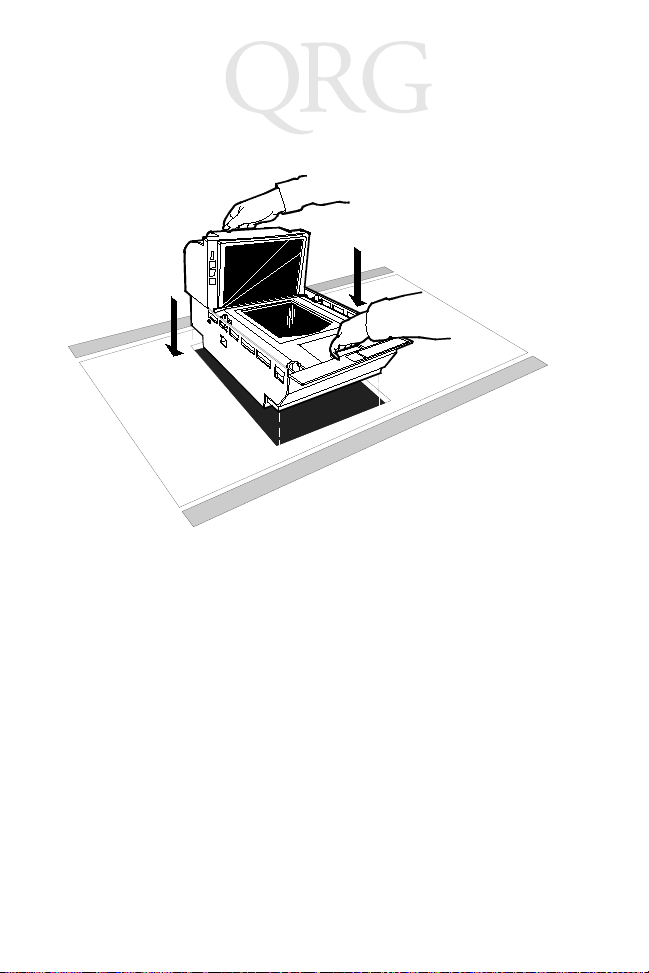
Installing 7875 into Checkstand Cutout
Grasp the 7875 Scanner/Scale and lower it into the checkstand
cutout. Be careful not to damage any of the cables. After the unit is
properly sitting on its supports, install the Top Plate.
Note: It is important that the 7875 does not rock on its sup-
ports. Make sure all adjustable supports are securely
fastened and that the 7875 is sitting on all supports.
11
Page 14
7875 Scanner / Scale
Align the 7875 to the Checkstand
The leading edge of the Top Plate must be flush or up to 1/16 in.
(0.15 cm) below the top of the checkstand. The trailing edge of the
Top Plate must be flush or up to 1/16 in. (0.15 cm) above the top of
the checkstand.
Note: The four adjustable support posts on the Scale Hinge
Assembly are set at the factory. Do not attempt to adjust
the Top Plate using these posts. Adjust the 7875 supports to align the Top Plate with the checkstand.
If the Top Plate is properly aligned with the checkstand, an item
should easily slide from the checkstand onto the Top Plate and then
from the Top Plate onto the checkstand. The following illustration
shows this alignment.
12
Page 15

Quick Reference
Low Surface
High Surface
Correct Alignment
Bad Alignment
Scanner Too High
Bad Alignment
Scanner Too Low
Low Surface
High Surface
Calibrate the Scale
Note: To comply with governmental weights and measures
regulations, you must be certified to perform the calibration function. Also, you MUST calibrate the scale
when you install an 7875 Scanner/Scale.
Note: Your 7875 Scanner/Scale may not have an integrated
display, and may not have a remote display when connected to some host terminals. If this is the case, a Field
13
Page 16

7875 Scanner / Scale
Service Calibration Display is required unless your 7875
has voice enabled. Calibration information is NOT sent
to the host terminal. Contact your Symbol representative about calibrating the scale.
Note: The interface cable between the 7875 and host terminal
must be disconnected during calibration. Some hosts
may cause interference that invalidates scale calibration.
You can calibrate the scale after power is supplied for 30 minutes if
the ambient air conditions are 68° F (20° C) for at least 24 hours. If
this condition has not been met, the scale must be on for at least 6
hours before you can calibrate it. Also, you must use a certified
weight set to calibrate and certify the scale.
The EEPROM on the scale board maintains an audit trail of scale
calibration and programming activity. The audit trail contains an
event counter that records the number of times the scale has been
calibrated. You can display the audit trail count on an integrated,
remote, or Field Service Calibration Display by pressing the Scale
Zero Button on the Operator Display Panel. The display alternates
between Cal xxx and PAr xxx.
Exercise the Scale
You must exercise the scale before performing a calibration. Add
and remove weight to your scale in the order provided in the
following chart. In this building procedure you start with no weight
(0) and sequentially add and remove weight to obtain the values
shown in the chart. Perform this procedure four times
We ig h t
Feature Total Weight on Top Plate
9.995 kg 0.0 kg 2.5 kg 5.0 kg 10. 0 kg 5.0 kg 2.5 kg 0.0 kg
13.995 kg 0.0 kg 2.5 kg 5.0 kg 15.0 kg 5.0 kg 2.5 kg 0.0 kg
30.0 lb. 0.0 lb. 5.0 lb. 15.0 lb. 30.0 lb. 15.0 lb. 5.0 lb. 0.0 lb.
.
14
Page 17

Quick Reference
Access the Calibration Switch
The Calibration Switch is located below the Top Plate. Remove the
Top Plate to access to the Calibration Switch cover. Lift the cover up
to remove.
Calibration
Switch Cover
Remove the screw that secures the Calibration Switch cover. Also
remove the seal if one is present. Rotate the Calibration Switch
cover to access to the Calibration Switch.
Calibration Switch
Security Cover
Screw
Wire Seal
Calibration
Switch
15
Page 18

7875 Scanner / Scale
Calibrate the Scale
1. Press the Scale Zero Button to display the Cal and PAr values.
Record these values.
2. Access the Calibration Switch, then place the top plate on the
unit before pressing the switch. Raise the front edge of the Top
Plate just enough to reach the switch.
3. Press the switch, then immediately lower the Top Plate into
position. The display should show
Ready C-00 kg (00 lb.)
.
4. Follow the steps in the following chart.
Display Add Weight Remove Weight
Ready C-2.5 kg (05 lb.) 2.50 kg (5.00 lb.)
Ready C-05 kg (15 lb.) 2.50 kg (10.00 lb.)
Ready C-10 kg (30 lb.) 5.00 kg (15.00 lb.)
Ready C-00 kg (00 lb.) 10.00 kg (30.00 lb.)
Ready 0.000 kg (0.00 lb.)
Verify the Calibration
The scale accuracy test meets government requirements of testing
the accuracy of the scale after performing a scale calibration. It
contains a series of four tests that must be run in the continuous
sequence given.
Increasing Load Test
This test checks the scale’s accuracy when incrementally adding
weight to the center of the top plate. Use weights that correspond to
the 7875 weight feature
Weig ht
Step
1 9.995 kg 0.1 kg 0.1 ± 0.00 kg
Feature Add Weight
13.995 kg 0.1 kg 0.1 ± 0.00 kg
30.0 lb. 0.2 lb. 0.2 ± 0.00 lb.
.
Remove
Weight Display Result
16
Page 19

Quick Reference
Step
2 9.995 kg 2.5 kg 0.1 kg 2.5 ± 0.00 kg
3 9.995 kg 2.5 kg 5.0 ± 0.005 kg
4 9.995 kg 2.5 kg 7.5 ± 0.005 kg
5 9.995 kg 2.495 kg 9.995 ± 0.005 kg
Weigh t
Feature Add Weight
13.995 kg 2.5 kg 0.1 kg 2.5 ± 0.00 kg
30.0 lb. 5.0 lb. 0.2 lb. 5.0 ± 0.00 lb.
13.995 kg 4.5 kg 7.0 ± 0.005 kg
30.0 lb. 5.0 lb. 10.0 ± 0.01 lb.
13.995 kg 3.0 kg 10.0 ± 0.005 kg
30.0 lb. 10.0 lb. 20.0 ± 0.01 lb.
13.995 kg 3.995 kg 13.995 ± 0.005 kg
30.0 lb. 10.0 lb. 30.0 ± 0.01 lb.
Remove
Weight Display Result
Note: Do NOT remove any weight from the Top Plate.
Over-Capacity Test
This test checks for the proper indication from the scale when too
much weight is placed on the top plate.
Note: This test must immediately follow the increasing load
test; do not remove any of the weights prior to running
this test.
Place additional weight on the center of the top plate as shown in
the following chart. Use the weight that corresponds to the 7875
weight feature. The display shows a series of dashes to indicate an
over-capacity condition.
Weigh t
Step
1 9.995 kg 0.04 kg --.---
Feature
13.995 kg 0.04 kg --.---
30.0 lb. 0.08 lb. --.---
Add
Weigh t
Remove
Weight Display Result
17
Page 20

7875 Scanner / Scale
Step
2 9.995 kg 0.04 kg 9.995 ± 0.005 kg
Weig ht
Feature
13.995 kg 0.04 kg 13.995 ± 0.005 kg
30.0 lb. 0.08 lb. 30.0 ± 0.01 lb.
Add
Weig ht
Remove
Weight Display Result
Note: Do NOT remove any weight from the Top Plate.
Decreasing Load Test
This test checks the scale’s accuracy when incrementally removing
weight from the top plate. Use weights that correspond to the 7875
weight feature.
Note: This test must immediately follow the over-capacity test;
do not remove any of the weights prior to running this
test.
Step
1 9.995 kg 2.495 kg 7.5 ± 0.005 kg
2 9.995 kg 5.0 kg 2.5 ± 0.00 kg
3 9.995 kg 0.1 kg 2.5 kg 0.1 ± 0.00 kg
4 9.995 kg 0.1 kg 0.0 ± 0.00 kg
Weig ht
Feature Add Weight
13.995 kg 3.995 kg 10.0 ± 0.005 kg
30.0 lb. 10.0 lb. 20.0 ± 0.01 lb.
13.995 kg 7.5 kg 2.5 ± 0.00 kg
30.0 lb. 15.0 lb. 5.0 ± 0.00 lb.
13.995 kg 0.1 kg 2.5 kg 0.1 ± 0.00 kg
30.0 lb. 0.2 lb. 5.0 lb. 0.2 ± 0.00 lb.
13.995 kg 0.1 kg 0.0 ± 0.00 kg
30.0 lb. 0.2 lb. 0.0 ± 0.00 lb.
Remove
Weight Display Result
18
Page 21

Quick Reference
Shift Test
This test involves moving a weight off the center point of the top
plate to check for continued accuracy.
1. Place 5.00 kg (15.00 lb.) of weight in position 1 on the Top
Plate.
2. Move the weight to position 2 on the Top Plate. The display
should show 5.00 ± 0.005 kg (15.00 ± 0.01 lb.).
3. Repeat step 2 for positions 3, 4, and 5.
4. Move the weight to position 1 again.
5. Remove all weights. The display should read 0.000 ± 0.000kg
(0.00 ± 0.00 lb.).
6. Raise and hold up the Top Plate. Record the Cal and PAr values shown on the display.
5
2
1
34
19
Page 22

7875 Scanner / Scale
Secure the Calibration Switch
When you perform a scale calibration, seal the Calibration Switch
cover with a lead/wire seal using a lead/wire seal press or a film/
paper seal (obtained locally). The type of seal you use depends on
your local laws; also, Weights and Measures officials may be
required to attach the seal.
Note: In the United States and Canada, the audit trail can serve
as an acceptable security seal.
Check the Scanner Operation
Make any necessary programming changes to the 7875, then scan
some bar codes to assure the scanner is working properly. The 7875
does not have an On/Off switch. Use the circuit breaker switch in
the checkstand to turn the unit on or off.
Setting the Program Parameters
Caution: Some host terminals can corrupt the 7875 program if
they are running and are connected to the 7875 while
you are making program changes. Either turn off the
host terminal or disconnect the interface cable before
scanning any programming tags.
To make changes to the program parameters, enter information
from the Programming Worksheets on page 29. The Programming
Worksheets identify all the available program parameters. Each
worksheet relates to a specific programming mode. Most
programming options have defaults, identified by a heavy box, that
are determined at the factory. Scanning the
tag after applying power to the unit sets the parameters to these
values.
20
Default
tag as the first
Page 23

Quick Reference
Change the 7875 program by scanning the proper sequence of
programming tags included with the unit. To make program
changes:
1. Enter the Base Programming state by scanning the
ming Mode
ing power.
2. Select a Programming Worksheet and enter its parameter data
by scanning the appropriate Hex tags.
3. Save the program by scanning the
Note: In most cases the factory-determined defaults are the
tag; this must be the first tag scanned after apply-
Save and Reset
correct parameter setting. However, if you do need to
make changes, first set all parameters to default values,
then make any necessary changes to the appropriate parameters.
Program-
tag.
Scan Sample Tags
Scan some sample tags to verify that the 7875 is communicating
with the host terminal. Following are four tags that you can use,
providing the programming options are enabled.
21
Page 24

7875 Scanner / Scale
UPC-A
77062 37920
1
4
Code 39
17706237920
Code 128
17706237920
017706237920
Interleaved 2 of 5
22
Page 25

Quick Reference
Operating the Scanner
The 7875 is a fixed-position device installed in a checkout counter,
and is not moved by the operator during operation. The 7875 is
maintained and serviced by trained service personnel only. The
operator has no access to any laser module components.
The7875 does not have a power switch. Turn it on and off using
the circuit breaker switch, located in the checkstand, that supplies
power to the unit. Be sure this switch is in the On position.
The Status Indicator on the Operator Display Panel is red when the
7875 is ready. To scan, slide an item from the checkstand across the
scanner, and back onto the checkstand. With a good scan, the Status
Indicator flashes green, then turns red. Nothing happens if the bar
code is not read.
Status Indicator
23
Page 26

7875 Scanner / Scale
Operating the Scale
The 7875 typically takes from 1.0 to 2.0 seconds to weigh an item,
depending on the item’s weight. Heavier items take longer. Before
weighing an item, make sure the scale displays all zeros. If not, press
the Scale Zero Button.
Note: Place the item you are weighing in the center of the Top
Plate. The item must fit completely on the Top Plate, and
not hang over onto the checkstand.
When the scale weighs an item, the Status Indicator flashes green
and a good weigh tone sounds. Nothing happens if the scale cannot
weigh an item.
Status Indicator
Integrated Display
Scale Zero Button
Top Plate
24
Page 27

Quick Reference
Cleaning
Keep the scan windows clean to keep the read rate exceptionally
high. During normal operation the scan windows can accumulate
dirt, which degrades performance to the point where the scanner
cannot read bar codes. The Please Clean Window indicator flashes
when the scan windows need cleaning. Use a soft cloth moistened
with a common, non-abrasive, liquid window cleaner to clean the
scan windows. Be sure to spray the cleaner onto the cloth, not
directly onto the 7875.
Note: Scale problems can occur from debris collecting under
the Top Plate. Be sure to keep the plastic subplate clean
to prevent interference with the Top Plate when weighing items.
Top Plate
Wiping Action
25
Plastic Subplate
Page 28

7875 Scanner / Scale
Correcting Scanner Problems
Problem
Scanner does
not operate
Scanner does
not operate
Scanner does
not operate
Scanner does
not read tags
Scanner reads
only two tags
Status
Indicator Tone
Red Off
Green Off
Red Flashing Green
Flashing
Red Flashing
Red Flashing
Red On Off 7875 is
Off No power
Off Sleep
Off Communi-
Off Internal
Possible
Cause Corrective Action
to the unit
mode
cations is
IBM 468x
and scanner is offline
failure
not communicating with
host terminal
Check electrical outlet for
proper power.
Verify the circuit breaker
switch is in the ON position.
Pass something in front of
the motion detector.
Verify that the IBM terminal is turned on.
Verify that the IBM terminal is recognizing the
7875.
Verify that the Interface
Cable is properly connected.
Remove power from the
7875 and then supply
power again. If the problem is not corrected, have
scanner repaired.
Verify that the Interface
Cable is properly connected.
Remove power from the
7875 and then supply
power again. If the problem is not corrected, have
scanner or host terminal
repaired.
26
Page 29

Quick Reference
Correcting Scale Problems
Problem Possible Cause Corrective Action
Error code 5---displays
Error code 4---displays
Error code 4---displays
Scale display is
blank
Scale drift Verify that nothing is on the scale.
Possible scale error Press Scale Zero button and retry. If
Slight vibration to
scale when calibrating
Top Plate is being
prevented from
moving down.
Lift the Top Plate and verify that no
objects are under it. Push Scale
Zero button. If error code persists,
have unit repaired.
error code persists, have unit repaired.
Calibrate scale, not permitting any
external scale movement while the
weights are on the scale.
Remove interference around edge
of Top Plate and checkstand.
Remove any foreign objects from
under the Top Plate.
27
Page 30

7875 Scanner / Scale
Determining the Communication Protocol
Use the following procedure to determine the communications
protocol programmed in your 7875.
1. Apply power to the 7875.
2. Scan the
scanned after applying power. Scan the
read tone for this tag sounds (three beeps).
If the 7875 has the Voice feature enabled, the communications
protocol is given audibly. If the Voice feature is not enabled,
the Status indicator flashes green and the 7875 beeps, identifying the communication protocol. Following are the number
of beeps that sound for each communication protocol.
1 Short, high-pitched beep OCIA NCR Short
1 Beep OCIA NCR Long
2 Beeps OCIA Non-NCR
3 Beeps IBM 468x
6 Beeps RS-232
7 Beeps OCIA Single-Cable
8 Beeps OCIA Dual-Cable
Diagnostic Mode
tag; this must be the first tag
Hex 3
Beeper Indications
Beep Sequence Indication
tag. The good
3. Remove power from the 7875.
28
Page 31

Quick Reference
Programming Worksheets
This section describes the options used to program your scanner/
scale using the bar codes in the
and letters in boxes represent Hex bar codes to scan when selecting
each option.
10
COMMUNICATIONS PROTOCOL
Protocol
0 1 2 3 4 5
OCIA
NCR Short
(Datachecker)
OCIA
NCR Long
Programming Tags Guide
OCIA
Non NCR
(Casio
4-Bit Parallel)
IBM 468x
Port 4A
(Slot Scanner)
IBM 468x
(HHBCR)
Port 4B
. Numbers
RS-232
6 7 A B C
OCIA
Single Cable
11
GOOD READ TONE
Tone On/Off
A
Tone Frequency
B
(Hertz)
Tone Length
C
(Milliseconds)
Tone Volume
D
Not-On-File
E
Tone Volume
IBM 1520
OCIA NCR
Dual Cable
0 1
Off On
B
C
D
E
OCIA
Non NCR
Dual Cable
When entering Tone Frequency, the adjustment can be
incremented upward by scanning the
time you scan the
increases one unit. Scan the
to end this mode.
When entering Tone Length, the adjustment can be
incremented upward by scanning the
time you scan the
one unit. Scan the
this mode.
When entering Tone Volume, the adjustment can be
incremented upward by scanning the
time you scan the
one unit. Scan the
this mode.
When entering Not-On-File Tone Volume, the adjustment
can be incremented upward by scanning the
Each time you scan the
increases one unit. Scan the
to end this mode.
(BCR)
4-Bit Parallel
Hex B tag, the tone frequency
Hex C tag, the tone length increases
End tag or a valid Hex tag to end
Hex D tag, the tone Volume increases
End tag or a valid Hex tag to end
Hex E tag, the tone Volume
Hex B tag. Each
End tag or a valid Hex tag
Hex C tag. Each
Hex D tag. Each
End tag or a valid Hex tag
29
TEC
Hex E tag.
Page 32

7875 Scanner / Scale
12
TIMERS
Lockout Time
A
(Milliseconds)
Restart
B
Lockout Timer
Active Time
C
(Minutes)
13
UPC/EAN
A
Version D
B
Extend UPC-A
C
To EAN-13
UPC/EAN
0 1 2 3 4 6 75
450 600 750 900 1050 1200 1350 1500
0 1
Off On
0 1 2 3
0153060
No Time-out ( Always Active)
Note: We recommend that you do not set the Active Time
parameter to 0. Leaving the laser light on all the time reduces
its life expectancy.
0 1
Disable Enable
0 1
None D-1
0 1
Disable Enable
2 3
D-2 D-3
4 5
D-4 D-5
Extend UPC-E
D
To UPC-A
Periodical Codes
E
Periodical Code
Extension
Send Data
0 1
Disable Enable
0 1
Disable Enable
0 1
2-Digit
5-Digit
Only
Only
0 1
Data As
Decoded
2
2-Digit &
5-Digit
Periodical Code
Data Only
30
2
2CF Hex
If Periodical Data
Not Decoded
Page 33

Quick Reference
1 4
CODE 39
Code 39
A
0 1
Disable Enable
Minimum Characters Allowed
B
Full ASCII
C
Check Digit Present
D
Transmit Check Digit
E
Allow One-Character Tags
F
1 5
INTERLEAVED 2 OF 5
Interleaved 2 of 5
A
Bar Code Length
B
Value 1 Characters
Value 2 Characters
Check Digit Present
C
0 1
Disable Enable
0 1
Range
Specific
Check
Check
0 1
Disable Enable
2 - F 4
0 1
Disable
Enable
0 1
Disable Enable
0
Disable Enable
0 1
Disable Enable
Minimum
Minimum
Default
1
0 - 5 0 - 9
Character 1 Character 2
Default
0 8
0 - 5 0 - 9
Character 1 Character 2
Default
1 6
Transmit Check Digit
D
0 1
Disable Enable
31
Page 34

7875 Scanner / Scale
1 7
CODE 128
Code 128
A
Minimum Data Characters Allowed
B
UCC 128
C
1 6
LABEL IDENTIFIERS
Identifier Type
A
Default Prefix
0
0 1
Disable Enable
1 2 3 4 5
0 1
Disable Enable
2
None
3
Unique Prefix
Common Byte 1
B
Common Byte 2
C
Bar Code Type
D
Common Byte
Unique Identifier
Version Number
(UPC-D Only)
0 - 7
Hex Character
0 - 7
Hex Character
0 1 2 3 4
UPC-A UPC-D UPC-E EAN-8 EAN-13
5 6 7
Code 39 Code 128 Interleaved
0 1 2 3
None Common Byte 1 Common Byte 2 Both Common Bytes
0 - 7
Hex Character
0
Do Not Include
0 - F
Hex Character
0 - F
Hex Character
2 of 5
0 - F
Hex Character
1
Include
Default
5 D
Default
4 2
Default: Varies according to
Bar Code Type.
32
Page 35

Quick Reference
2 0
RS-232 PARAMETERS - SET 1
Baud Rate
A
Parity
B
Stop Bits And
C
Character
Length
Handshake
D
2 1
RS-232 PARAMETERS - SET 2
BCC Options
A
Interface Control
B
Check Digit
C
0
300160021200324004480059600619200
0
Odd1Even4None
0
1 Stop Bit
7-Bit Character
0
RTS Low
CTS Ignored
3 4 5
Raise RTS
Ignore CTS
0
Disable1Enable
0
None1ACK/NAK2XOn/XOff3ACK/NAK & XOn/XOff
Disable UPC-A
Disable EAN-8
Disable EAN-13
Disable UPC-E
Note: Check Digit parameter also applies to UPC-E
8-Bit Character
RTS High
CTS Ignored
RTS Low
Wait for CTS
0
when using for OCIA communications.
Note: Parity must be Odd or Even on a
1
1 Stop Bit
1
Raise RTS
Wait for CTS
RTS High
Wait for CTS
Default: 7870/7875-1000 - Disable
7870/7875-2000 - Enable
1
Enable UPC-A
Enable EAN-8
Enable EAN-13
Disable UPC-E
7870/7875;
None is selected.
7-Bit Character
Odd is used if
2
2 Stop Bits
2
2
Disable UPC-A
Disable EAN-8
Disable EAN-13
Enable UPC-E
3
2 Stop Bits
8-Bit Character
3
Enable UPC-A
Enable EAN-8
Enable EAN-13
Enable UPC-E
33
Page 36

7875 Scanner / Scale
2 2
RS-232 PREFIX BYTE
Prefix Byte
A
0
Disable1Enable24 Comma Prefix On34 Comma Prefix Off
ASCII Code
B
2 3
RS-232 TERMINATOR BYTE
Terminator Byte
A
ASCII Code
B
2 4
RS-232 COMMUNICATIONS OPTIONS
Message Delay
Scanner or
Scanner/Scale Format
Normal or
Eavesdrop Mode
0 - 7
Hex Character
(ASCII Code Chart)
0
Disable1Enable
0 - 7
Hex Character
(ASCII Code Chart)
Scanner Only5Scanner/Scale
Normal Mode7Eavesdrop Mode
0 - F
Hex Character
(ASCII Code Chart)
Note: A Terminator Byte is required on a
7870/7875. If you select
Disable , it is ignored and an
ETX (03) is sent.
0 - F
Hex Character
(ASCII Code Chart)
0
No Delay110ms Delay250ms Delay
4
6
0 2
0 3
Default
Default
34
Page 37

Quick Reference
3 0
SCALE PARAMETERS
Model Number
IBM Address
Speak Display Price
3 2
MISCELLANEOUS PARAMETERS
5-Second Weight Display Timer
IBM Tone Control
(Good Read Tone Control)
OCIA Price Display
IBM Rexmit Control
OCIA Blank Display in Price Mode
Enable/Disable Voice Messages
IBM Tag Data Format
3
Scanner/Scale4Scanner Only
5
Address 6A6Address 6B7Address 6E
B
Toggle On and Off
1
Disable2Enable
3
Disable4Enable
5
Disable6Enable
7
3 Times8Forever
9
DisableAEnable
Default: Enabled
D
Toggle
E
HexFASCII
35
Page 38

7875 Scanner / Scale
3 6
Dual Cable Interface Options
Scale Type
A
0
No Adapter -
Exit Parameter
1
Avery2Weightronix3Tec
Parallel
4
Casio
Parallel
5
Datachecker6Toledo
ASCII Code Chart
ASCII Code Chart
30
NULL
SOH
STX
ETX
EOT
ENQ
ACK
BEL
BS
HT
LF
VT
FF
CR
S0
S1
10
11
12
13
14
15
16
17
18
19
1A
1B
1C
1D
1E
1F
00
01
02
03
04
05
06
07
08
09
0A
0B
0C
0D
0E
0F
DLE
DC1
DC2
DC3
DC4
NAK
SYN
ETB
CAN
EM
SUB
ESC
FS
GS
RS
US
20
21
22
23
24
25
26
27
28
29
2A
2B
2C
2D
2E
2F
0
SP
31
1
!
32
2
"
33
3
#
34
4
$
35
5
%
36
6
&
37
7
'
38
8
(
39
)
9
3A
*
:
3B
;
+
3C
,
<
3D
-
=
3E
.
>
3F
/
?
50
40
41
42
43
44
45
46
47
48
49
4A
4B
4C
4D
4E
4F
P
@
51
Q
A
52
R
B
53
S
C
54
T
D
55
U
E
56
V
F
57
W
G
58
X
H
59
Y
I
5A
Z
J
5B
[
K
5C
\
L
5D
]
M
5E
^
N
5F
_
O
70
60
61
62
63
64
65
66
67
68
69
6A
6B
6C
6D
6E
6F
p
71
q
a
72
r
b
73
s
c
74
t
d
75
u
e
76
v
f
77
w
g
78
x
h
79
y
i
7A
z
j
7B
{
k
7C
|
l
7D
}
m
7E
n
7F
DEL
o
36
Page 39

Quick Reference
Regulatory Information
Radio Frequency Interference Requirements
This device has been tested and found to comply with the limits for a Class A digital
device pursuant to Part 15 of the Federal Communications Commissions Rules and
Regulation. These limits are designed to provide reasonable protection against harmful
interference when the equipment is operated in a commercial environment. This
equipment generates, uses, and can radiate radio frequency energy and, if not installed
and used in accordance with the instruction manual, may cause harmful interference to
radio communications. Operation of this equipment in a residential area is likely to
cause harmful interference in which case the user will be required to correct the
interference at his own expense.
However, there is no guarantee that interference will not occur in a particular
installation. If the equipment does cause harmful interference to radio or television
reception, which can be determined by turning the equipment off and on, the user is
encouraged to try to correct the interference by one or more of the following measures:
• Re-orient or relocate the receiving antenna.
• Increase the separation between the equipment and receiver.
• Connect the equipment into an outlet on a circuit different from that which the
receiver is connected.
• Consult the dealer or an experienced radio/TV technician for help.
Radio Frequency Interference Requirements - Canada
This Class B digital apparatus complies with Industry Canada Standard ICES-003.
Cet appareil numérique de la classe B est conform à la norme NMB-003 d’Industrie
Canada.
Voluntary Control Council for Interference (VCCI) Radio Frequency Interference Statement
Scale Regulatory
Country, state, and local regulatory agency notification of an installation of a weighing
instrument or Point of Service terminal’s device is required. Failure to comply with
government Weights and Measures regulations can result in criminal prosecution of
individuals and can jeopardize the ability to conduct normal business. The 7875
Scanner/Scale has been certified in many countries. Contact the NCR office of Weights
& Measures and Laser Safety for specific country approvals.
37
Page 40

7875 Scanner / Scale
CE Marking and European Union Compliance
Products intended for sale within the European Union are marked with the
CE Mark which indicates compliance to applicable Directives and
European Normes (EN), as follows. Amendments to these Directives or
ENs are included:
Applicable Directives
• Electromagnetic Compatibility Directive 89/336/EEC
• Low Voltage Directive 73/23/EEC
Applicable Standards
• EN 55 022 - Limits and Methods of Measurement of Radio Interference Characteristics of Information technology Equipment
Warning:
product may cause radio interference in which case the user may be
required to take adequate measures.
• EN 50 082-1:1997 - Electromagnetic Compatibility - Generic Immunity Standard, Part 1: Residential, commercial, Light Industry
• IEC 1000-4-2(1995-01) - Electromagnetic compatibility (EMC) - Part 4:Testing
and measurement techniques - Section 2: Electrostatic discharge immunity test.
• IEC 1000-4-3(1995-03) - Electromagnetic compatibility (EMC) - Part 4:Testing
and measurement techniques - Section 3: Radiated, radio-frequency, electromagnetic field immunity test.
• EN 60 950 + Amd 1 + Amd 2 - Safety of Information Technology Equipment
Including Electrical Business Equipment
• EN 60 825-1 (EN 60 825) - Safety of Devices Containing Lasers
This is a Class A product. In a domestic environment this
Laser Devices
Symbol products using lasers comply with US 21CFR1040.10, Subchapter J and
IEC825/EN 60 825 (or IEC825-1/EN 60 825-1, depending on the date of
manufacture). The laser classification is marked on one of the labels on the product.
Class 1 Laser devices are not considered to be hazardous when used for their intended
purpose. The following statement is required to comply with US and international
regulations:
Caution: Use of controls, adjustments or performance of procedures other than those
specified herein may result in hazardous laser light exposure.
Class 2 laser scanners use a low power, visible light diode. As with any very bright light
source, such as the sun, the user should avoid staring directly into the light beam.
Momentary exposure to a Class 2 laser is not known to be harmful.
38
Page 41

Quick Reference
Scanner Labeling
This laser module
does not comply
with 21CFR1040.
Use only as a
component.
Class IIa Laser Product. Avoid Long-term Viewing of direct Laser Light.
Appareil à Laser de classe IIa Eviter Toute Exposition
Prolongèe de la vue à la lumiè re laser directe.
Class IIa Producto Laser. Tratè De no ver directamente èl Rayo
Laser por mucho tiempò. (IEC CLASS 1 LASER PRODUCT)
C
39
Page 42

7875 Scanner / Scale
In accordance with Clause 5, IEC 0825 and EN60825, the following information is
provided to the user:
ENGLISH HEBREW
CLASS 1 CLASS 1 LASER PRODUCT
CLASS 2 LASER LIGHT
DO NOT STARE INTO BEAM
CLASS 2 LASER PRODUCT
DANISH
KLASSE 1 KLASSE 1 LASERPRODUKT
KLASSE 2 LASERLYF CLASSE 1 PRODOTTO AL LASER DI CLAS SE 1
SE IKKE IND I STRÅLEN CLASSE 2 LUCE LASER
KLASSE 2 LASERPRODUKT NON FISSARE IL RAGGIOPRODOTTO
AL LASER DI CLASSE 2
DUTCH
KLASSE 1 KLASSE-1 LASERPRODUKT
KLASSE 2 LASERLICHT KLASSE 1 LASERPRODUKT, KLASSE 1
NIET IN STRAAL STAREN KLASSE 2 LASERLYS IKKE STIRR INN I LYSSTRÅLEN
KLASSE-2 LASERPRODUKT LASERPRODUKT, KLASSE 2
FINNISH PORTUGUESE
LUOKKA 1 LUOKKA 1 LASERTUOTE CLASSE 1 PRODUTO LASER DA CLASSE 1
LUOKKA 2 LASERVALO
ÄLÄ TUIJOTA SÄDETTÄ CLASSE 2 LUZ DE LASER NÃO FIXAR O RAIO LUMINOSO
LUOKKA 2 LASERTUOTE PRODUTO LASER DA CLASSE 2
FRENCH SPANISH
CLASSE 1 PRODUIT LASER DE CLASSE 1 CLASE 1 PRODUCTO LASER DE LA CLASE 1
CLASSE 2 LUMIERE LASER CLASE 2 LUZ LASER
NE PAS REGARDER LE RAYON FIXEMENT NO MIRE FIJAMENTE EL HAZ
PRODUIT LASER DE CLASSE 2 PRODUCTO LASER DE LA CLASE 2
GERMAN SWEDISH
KLASSE 1 LASERPRODUKT DER KLASSE 1 KLASS 1 LASERPRODUKT KLASS 1
KLASSE 2 LASERSTRAHLEN KL ASS 2 LASERLJUS STIRRA INTE MOT STRÅLEN
NICHT DIREKT IN DEN LASERSTRAHL SCHAUEN LASERPRODUKT KLASS 2
LASERPRODUKT DER KLASSE 2
ITALIAN
NORWEGIAN
40
Page 43

Quick Reference
Service Information
Before you use your unit, it must be configured to operate in your facility’s network and
run your applications.
If you have a problem with running your unit or using your equipment, contact your
facility’s Technical or Systems Support. If there is a problem with the equipment, they
will contact the Symbol Support Center:
United States 1-800-653-5350 Canada 905-629-7226
United Kingdom 0800 328 2424 Asia/Pacific 337-6588
Australia 1-800-672-906 Austria 1-505-5794
Denmark 7020-1718 Finland 9 5407 580
France 01-40-96-52-21 Germany 6074-49020
Italy 2-484441 Mexico 5-520-1835
Netherlands 315-271700 Norway 66810600
South Africa 11-4405668 Spain 9-1-320-39-09
Sweden 84452900
Latin America Sales Support 1-800-347-0178 Inside US
Europe/Mid-East Distributor Operations Contact local distributor or call
+1-561-483-1275 Outside US
+44 118 945 7360
Warranty
Symbol Technologies, Inc. (“Symbol”) manufactures its hardware products in
accordance with industry-standard practices. Symbol warrants that for a period of
twelve (12) months from date of shipment, products will be free from defects in
materials and workmanship.
This warranty is provided to the origin al owner only and is not transferable to any third
party. It shall not apply to any product (i) which has been repaired or altered unless
done or approved by Symbol, (ii) which has not been maintained in accordance with
any operating or handling instructions supplied by Symbol, (iii) which has been
subjected to unusual physical or electrical stress, misuse, abuse, power shortage,
negligence or accident or (iv) which has been used other than in accordance with the
product operating and handling instructions. Preventive maintenance is the
responsibility of customer and is not covered under this warranty.
Wear items and accessories having a Symbol serial number, will carry a 90-day limited
warranty. Non-serialized items will carry a 30-day limited warranty.
41
Page 44

Warranty Coverage and Procedure
During the warranty period, Symbol will repair or replace defective products returned
to Symbol Technologies. For warranty service in North America, call the Symbol
Support Center at 1-800-653-5350. International customers should contact the local
Symbol office or support center. If warranty service is required, Symbol will issue a
Return Material Authorization Number. Products must be shipped in the original or
comparable packaging, shipping and insurance charges prepaid. Symbol will ship the
repaired or replacement product freight and insurance prepaid in North America.
Shipments from the US to other locations will be made F.O.B. Symbol’s manufacturing
plant. Shipments from Symbol’s repair facilities outside the US will be made F.O.B.
Symbol’s repair facility.
Symbol will use new or refurbished parts at its discretion and will own all parts
removed from repaired products. Customer will pay for the replacement product in
case it does not return the replaced product to Symbol within 3 days of receipt of the
replacement product. The process for return and customer’s charges will be in
accordance with Symbol’s Exchange Policy in effect at the time of the exchange.
Customer accepts full responsibility for its software and data including the appropriate
backup thereof.
Repair or replacement of a product during warranty will not extend the original
warranty term.
Symbol’s Customer Service organization offers an array of service plans, such as onsite, depot, or phone support, that can be implemented to meet customer’s special
operational requirements and are available at a substantial discount during warranty
period.
General
Except for the warranties stated above, Symbol disclaims all warranties, express or
implied, on products furnished hereunder, including without limitation implied
warranties of merchantability and fitness for a particular purpose. The stated express
warranties are in lieu of all obligations or liabilities on part of Symbol for damages,
including without limitation, special, indirect, or consequential damages arising out of
or in connection with the use or performance of the product.
Seller’s liability for damages to buyer or others resulting from the use of any product,
shall in no way exceed the purchase price of said product, except in instances of injury
to persons or property.
Some states (or jurisdictions) do not allow the exclusion or limitation of incidental or
consequential damages, so the proceeding exclusion or limitation may not apply to you.
70-37658-01
Revision A — April 1999
Symbol Technologies, Inc. One Symbol Plaza Holtsville, NY 11742-1300
 Loading...