

Page 1

PTC-960X
User's Guide
Page 2

On December 1, 2000 Symbol T echnologies, Inc. completed the purchase
of Telxon Corporation. References made throughout this document to
"Telxon" or "Telxon Corporation" are be replaced with "Symbol" or
"Symbol Technologies, Inc.", respectively. Any questions, contact your
Symbol representative.
© 2000 by Symbol Technologies, Inc. All rights reserved.
No part of this publication may be reproduced or used in any form, or by any electrical or
mechanical means, without permission in writing from Symbol. This includes electronic or
mechanical means, such as photocopying, recording, or information storage and retrieval
systems. The material in this manual is subject to change without notice.
Symbol reserves the right to make changes to any software or product to improve reliability ,
function, or design.
Symbol does not assume any product liability arising out of, or in connection with, the
application or use of any product, circuit, or application described herein.
No license is granted, either expressly or by implication, estoppel, or otherwise under any
Symbol Technologies, Inc., intellectual property rights. An implied license only exists for
equipment, circuits, and subsystems contained in Symbol products.
Symbol is a registered trade mar k of Symbo l Technologies, Inc. Other product names
mentioned in this manual may be trademarks or registered trademarks of their respective
companies and are hereby ack nowl edg ed.
Symbol Technologies, Inc.
One Symbol Pl aza
Holtsville, New York 11742-1300
http://www.symbol.com
Symbol Support Center: 1- 800 -653- 53 50
2
Page 3

GUIDE TO THE
PTC-960X
Page 4

G
uide to the
PTC-960X
Part Number: 16670-701-01
Release Date: 9/17/93
Page 5

Telxon, TCAL (Telxon Common Application Language), and RAMSaver are registered trademarks of Telxon Corporation.
MS-DOS is a registered trademark of Microsoft
Corporation.
The information contained in this manual is
subject to change without notice.
Telxon Corporation shall not be liable for
technical or editorial omissions or mistakes in
this manual nor shall it be liable for incidental
or consequential damages res u lt ing fr om your
use of the information contained in this manual.
This manual is copyrighted. All rights are
reserved. No part of this manual may be
photocopied or reproduced in any form without
the prior writt en consent of Telxon.
© Copyright 1993 Telxon Corporation
All Rights Reserved.
Page 6

ÄÄ
ontents
C
FCC statement
Safety information
PTC equipped with a short-range laser scanner9
PTC equipped with a long-range laser scanner10
Disposing of nickel-cadmium batteries . . . . 10
. . . . . . . . . . . . . . . . . . . . . . . . 11
Scope
Overview of the PTC-960X
Entering data . . . . . . . . . . . . . . . . . 13
Communicating data . . . . . . . . . . . . . 13
Flash programming . . . . . . . . . . . . . . 13
Getting started
Unpacking the PTC-960X . . . . . . . . . . . 14
Installing the battery pack . . . . . . . . . . 15
Charging the battery pack . . . . . . . . . . 15
Checking the PTC-960X . . . . . . . . . . . 16
. . . . . . . . . . . . . . . . . . . . . . . . 17
Parts
Accessory connector . . . . . . . . . . . . . . 17
Bar-code scanner . . . . . . . . . . . . . . . 17
Bar-code scanner trigger . . . . . . . . . . . 17
Battery charger . . . . . . . . . . . . . . . . 19
Battery compartment . . . . . . . . . . . . . 19
Communication contacts . . . . . . . . . . . 19
Display . . . . . . . . . . . . . . . . . . . . . 19
End cap/battery pack assembly . . . . . . . . 20
Flash EPROM . . . . . . . . . . . . . . . . . 20
Handle . . . . . . . . . . . . . . . . . . . . . 21
Keyboard . . . . . . . . . . . . . . . . . . . 21
ENTER/YES key . . . . . . . . . . . . . 22
ON/OFF key . . . . . . . . . . . . . . . . 22
SHIFT key . . . . . . . . . . . . . . . . . 22
. . . . . . . . . . . . . . . . . . . . 8
. . . . . . . . . . . . . . . . . . 9
. . . . . . . . . . . . . 12
. . . . . . . . . . . . . . . . . . . 14
4
Page 7

Keyboard overlay . . . . . . . . . . . . . . . 22
RJ-41-to-RS-232 adapter cable (optional) . . 23
Status indicators . . . . . . . . . . . . . . . 23
Charging . . . . . . . . . . . . . . . . . . 23
Good Scan . . . . . . . . . . . . . . . . . 23
Low Bat . . . . . . . . . . . . . . . . . . 24
Scan . . . . . . . . . . . . . . . . . . . . 24
Wrist strap . . . . . . . . . . . . . . . . . . 24
Features
Communication and connections
Scanning bar-code labels
Maintaining the PTC-960X
. . . . . . . . . . . . . . . . . . . . . . 25
Autodiscrimination between bar codes . . . . 25
Automatic off . . . . . . . . . . . . . . . . . 25
Automatic return at on . . . . . . . . . . . . 25
Backlight . . . . . . . . . . . . . . . . . . . 25
Battery backup . . . . . . . . . . . . . . . . 26
Beeper . . . . . . . . . . . . . . . . . . . . . 26
Clock . . . . . . . . . . . . . . . . . . . . . 27
Communication . . . . . . . . . . . . . . . . 27
Display contrast . . . . . . . . . . . . . . . . 27
Memory . . . . . . . . . . . . . . . . . . . . 28
. . . . . . . . . . . 29
Connecting cables . . . . . . . . . . . . . . . 29
Disconnecting cables . . . . . . . . . . . . . 32
Connecting to the optional
communication cradle . . . . . . . . . . . 33
. . . . . . . . . . . . . . 34
. . . . . . . . . . . . . 36
Operating conditions . . . . . . . . . . . . . 36
Handling the PTC-960X . . . . . . . . . . . 36
Storing the PTC-960X . . . . . . . . . . . . 37
Cleaning the PTC-960X . . . . . . . . . . . . 38
Servicing the PTC-960X . . . . . . . . . . . 38
Replacing the battery pack
Removing the battery pack . . . . . . . . . . 39
Installing a new battery pack . . . . . . . . 40
. . . . . . . . . . . . . 39
5
Page 8

Programming the flash EPROM
Before you begin . . . . . . . . . . . . . . . . 41
Procedure . . . . . . . . . . . . . . . . . . . 43
. . . . . . . . . . . 41
Troubleshooting
If the PTC does not turn on . . . . . . . . . . 49
If the bar-code scanner does not read a labe l 49
If you experience any other problems with
your PTC-960X . . . . . . . . . . . . . . 50
Appendix A
Specifications . . . . . . . . . . . . . . . . . 51
Physical . . . . . . . . . . . . . . . . . . 51
Electrical . . . . . . . . . . . . . . . . . 51
Bar code types supported . . . . . . . . . 52
Communication . . . . . . . . . . . . . . 53
Appendix B
Accessory part numbers . . . . . . . . . . . 54
Appendix C
Communication connections . . . . . . . . . 56
Appendix D
LED status indicators . . . . . . . . . . . . . 64
Glossary
. . . . . . . . . . . . . . . . . . . 49
. . . . . . . . . . . . . . . . . . . . . 51
. . . . . . . . . . . . . . . . . . . . . 54
. . . . . . . . . . . . . . . . . . . . . 56
. . . . . . . . . . . . . . . . . . . . . 64
. . . . . . . . . . . . . . . . . . . . . . 65
. . . . . . . . . . . . . . . . . . . . . . . . 69
Index
Figures
1.Parts of the PTC-960X . . . . . . . . . . 18
2.Connecting a cable . . . . . . . . . . . . 31
3.Scanning a bar-code . . . . . . . . . . . . 35
4.Removing the battery pack . . . . . . . . 39
5.RJ-41-to-RS-232 25-pin adapter cable . . 56
6.RJ-41-to-RS-232 9-pin adapter cable . . . 57
7.PTC-to-1/2 duplex modem cable . . . . . 58
8.PTC-to-full duplex modem cable . . . . . 59
9.PTC-to-host (DTE) cable . . . . . . . . . 60
6
Page 9

10.Cloning cable, RJ-41-to-RJ-41 . . . . . . 61
11.PTC-to-IBM PC/AT download cable . . . 62
12.PTC-to-IBM PC/XT download cable . . . 63
Tables
1.Accessory part numbers . . . . . . . . . 54
2.LED status indicators . . . . . . . . . . . 64
7
Page 10

ÄÄ
CC
F
statement
This equipment has been tested and found to
comply with the limits for a Class A digital device, pursuant to Part 15 of the Federal
Communication Commissio n (F CC) ru les. These
limits are designed to prov id e reasonable protection against harmful interference when the
equipment is operated in a commercial environment. This equipment generates, uses, and can
radiate radio frequency energy and, if not installed and used in accordance with thi s
instruction manual, may cause harmful interference to radio communications. Operation of this
equipment in a residential are a is likely to cause
harmful interference, in which case users will be
required to correc t the interference at their ow n
expense.
8
Page 11
ÄÄ
afety
S
information
©
PTC equipped with a short- range laser scanner
This product is a Class II laser product. I t emits
a 1.0-milliwatt beam of laser light from the output window. No maintenance is required to keep
this product in compliance with U.S. Department of Health and Human Services (DHHS)
regulation 21 C.F.R. subchapter J. No controls
are provided for operation or maintenance. Laser
light in excess of Class I limits is inside an internal protective cover. Do not stare into the beam
if the protective cover is removed.
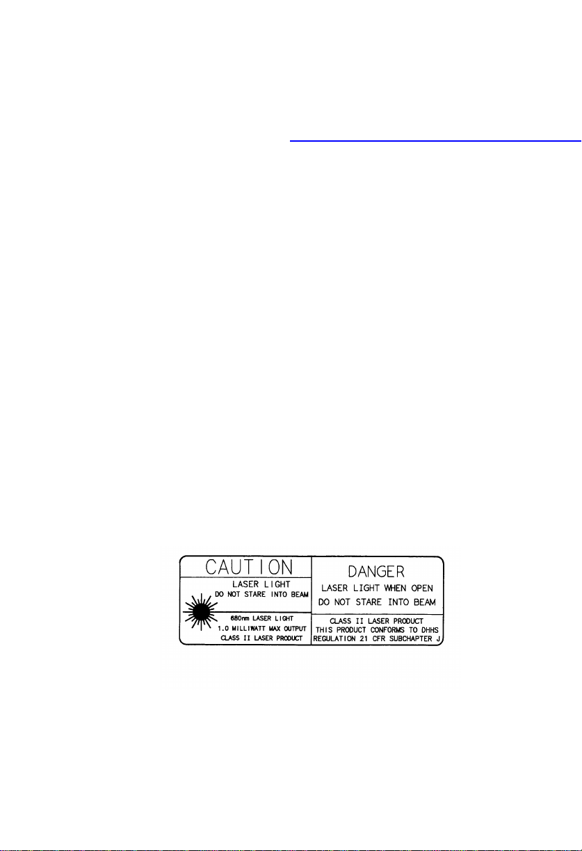
The laser safety w arning label required by the
DHHS for the PTC-960X equipped with a shortrange laser scanner is illustrated below. This
yellow and black label is located on the bottom
of the PTC-960X near the scanning window.
9
Page 12
©
PTC equipped with a long -range laser scanner
This product is a Class IIIA laser product. It
emits a 5.0-milliwatt beam of laser light from
the output window. No maintenance is required
to keep this product in compliance with DHHS
regulation 21 C.F.R. subchapter J. No controls
are provided for operation or maintenance. Laser
light in excess of Class I lim it s is inside an internal protective cover. Do not stare into the beam
if the protective cover is removed.
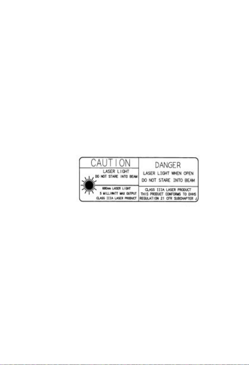
The laser safety w arning label required by the
DHHS for the PTC-960X equipped with a longrange laser scanner is illustrated below. This red
and black label is located on the bottom of the
PTC-960X near the scanning window.
©
Disposing of nickel-cadmium batteries
Nickel-cadmium batterie s cont ain chemically
active materials that are hazardous to the
environmen t; therefore, they must be dispos ed
of properly. Never attempt to in cinerate a nickelcadmium battery; doing so could cause it to
explode. Telxon urges you to contact the Environmental Protection Agency, the Department of
Natural Resources, a local hazardous waste disposal agency, or the Telxon Customer Support
Center for assistance prior to disposing of your
nickel-cadmium batteries.
10
Page 13

ÄÄ
cope
S
This manual provides general informati on on
how to operate, handle, and maintain the PTC960X. Use this manual as an introduction to the
PTC-960X along with the manual or instructions
provided by your supervisor.
This manual does not provide instructions on
how to perform the tasks specific to your job in
your organization. For that information, refer to
the manual or instructions provided by your
supervisor.
11
Page 14

ÄÄ
verview
O
of the PTC-960X
The Telxon PTC-960X is a battery-powered,
hand-held computer used to collect, store, and
transmit data. The PTC-960X has a built-in barcode scanner. Options for transmitting data over
telephone lines and printing are also avail able.
The PTC-960X automates your data collection
procedures an d is cu stom programmed to ef ficiently handle your organization’s unique data
collection appli cat ions.
The PTC-960X is designed for use in areas
where dust, dirt, or moisture can be excessive.
The PTC has been specially sealed to resist these
hazards.
Because the PTC-960X is custom programmed
for each organization, this manual does not include the specific operating instructions for you r
organization ’s unique PTC data collection program. Operating instructions and training for
your PTC’s application program should be available from your sup ervisor.
The PTC runs an application program specially
designed to col lect data for your organization.
This program leads you through the application
with a series of display messages, prompts, and
beeps. Messages tell you when you make an
error and provide information on the application
or the PTC’s status. Prompts and beeps tell you
when to enter data, what type of data to enter,
and when you complete certain oper ations.
12
Page 15

©
Entering data
You can enter data into the PTC-960X using
either the keyboard or the built-in scanne r.
When you press a key on the PTC’s keyboard,
the corresponding numb er or letter appears on
the display. Pressing the ENTER key stores the
data in the PTC’s memor y.
The built-in bar-code scanner can “read” a bar
code. A bar code is a series of vertical bars and
spaces that you find on nearly every item in
business today. The PTC interprets the scanned
data, may show thi s data on the display, and can
store the data in the PTC’s me mory.
©
Communicating data
After collecting the da ta , the PTC must either
transmit the data to a host compute r fo r processing or send it to a pr in ter, or both, to ma ke th e
data useful to you and your organization. The
PTC-960X is capable of transmitting data
through an optional communica ti on cradle or by
being connected by cable to a host computer,
printer, or other accessory.
©
Flash programming
The PTC-960X contains a flash EPROM, which
is an electronic chip that contains the PTC’s
application program. The flash EPROM can be
reprogrammed ( flas hed) while it is inside the
PTC, making updating and changing application
programs easy.
13
Page 16

ÄÄ
etting
G
started
©
Unpacking the PTC-960X
The PTC-960X is shipped in a single box
containing
a PTC-960X,
•
a battery charger,
•
a wrist strap,
•
a nickel-cadmium battery pack,
•
the Guide to the PTC-960X,
•
the Guide to the FLASH Utilities (TCAL
•
or MS-DOS Version), and
the Guide to Maintaining NiCd Batteries.
•
Any cables or additional accessories are shipped
separately. Accessories have their own manuals.
1. Remove the PTC from the box.
2. Re move all packing material from the PTC.
Save the packing material in cas e the PTC is
ever stored or shipped to Telxon for service.
3. Check the contents of the package to make
sure you have received everything ordered.
4. Check the PTC and accessories for shipping
damage. Pay particular attention to the PTC
case, display lens, and scanner lens.
14
Page 17

If anything is missing or dama ged, notify your
Telxon service representative.
©
Installing the battery pack
1.Make sure the PTC is off.
2.Line up the end cap/battery pack assembly
with the openin g in the bottom of the PT C ’s
handle. See Figure 1 on page 18 for the location of the battery pack op enin g.
3.Slide the battery pack into the handle until
the end cap presses agai n s t th e body of the
handle and the tabs on the end cap lock the
assembly into place. Th e cu rved sides of the
end cap allow the battery pack t o be ins talled
in only one way.
©
Charging the battery pack
Equipment required :
One battery charger for each PTC
•
An electrical outlet within 6 feet (1.8 me-
•
ters) providing 110 volts AC in the U.S.
and Canada or 220 volts AC elsewhere
Use this procedure t o rechar g e the nick el- cad mium battery pack installed in the PTC’s handl e.
1.Make sure the PTC is off.
2.Disconnect all accessories from the PTC.
3.Lay the PTC-960X on its right side so the
charger connector is facing you.
4.Attach the end of the battery charger’s cabl e
to the charger con n ector on the PTC’s side.
15
Page 18

See Figure 1 on page 18 for the location of
the charger connector.
5.Plug the battery charger into a standard 110-
volt electrical outlet (220 volts outsid e the
U.S. and Canada).
6.Charge the battery pack for 12 hours.
7.When charging is finished, first unplug the
battery charger fr om the electrical outlet;
then disconnect it from the PTC.
©
Checking the PTC-960X
1.Press the ON/OFF key on the PTC’s key-
board to turn on the PTC.
2.Look at the PTC’s display.
3.What appears on the display depe nds on the
program your organization uses.
If the PTC is operating correctly, you should
not see or hear any of the following:
Low battery warning
•
A blank display screen
•
Any warning beeps
•
See the “Troubleshooting” section on page 49
if the PTC-960X is not operating correctly.
16
Page 19

ÄÄ
arts
P
©
©
Figure 1 shows the parts of the PTC-960X.
Accessory connector
A modular RJ-41-type co n n ector for accessories
is located on the PTC’s left s ide. O ne of a number
of special cables that plug into the connector can
be used to connect the PTC-960X to a particular
computer, printer, or other acces s ory. Cable part
numbers are listed in Appendix B, and cable diagrams are illustrated in Appendix C.
Bar-code scanner
A bar-code laser scanner, which is mounted i nside the PTC’s nose, lets you enter data into your
PTC by “reading” (scanning) bar-code labels.
Your PTC’s application program determines the
types of bar-code labels the PTC can read.
©
Bar-code scanner trigger
The trigger on the front of the PTC’s handle turns
on the PTC’s bar-code sc anne r when you are r ea dy
to read a bar code. Pressing the trigger also turns
on the PTC-960X if this option has been installed
by your organization.
17
Page 20
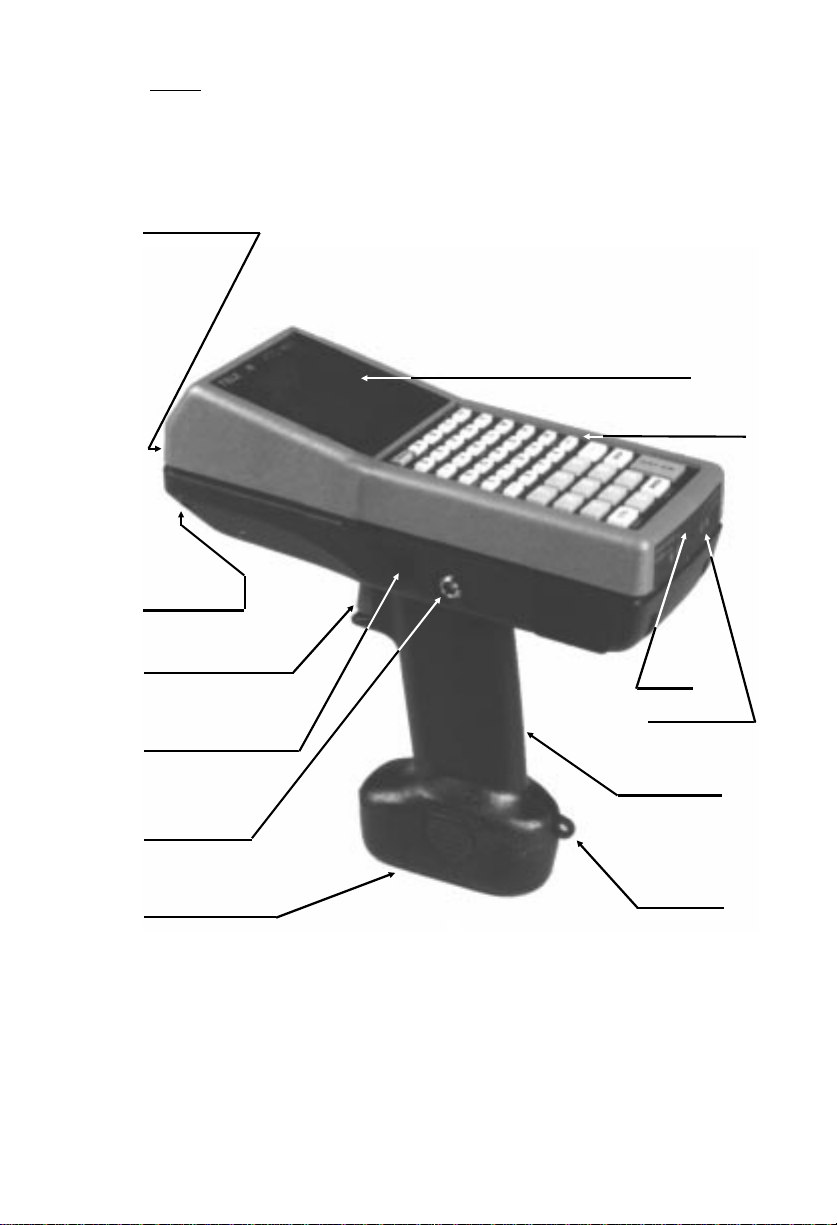
FIGURE 1
Parts of the PTC-960X
BAR-CODE SCANNER
COMMUNICATION
CONTACTS
DISPLAY
KEYBOARD &
KEYBOARD OVERLAY
BAR-CODE SCANNER TRIGGER
ACCESSORY CONNECTOR
BATTERY CHARGER
CONNECTOR
ENDCAP/BATTERY PACK
ASSEMBLY
BEEPER
STATUS INDICATORS
HANDLE &
BATTERY
COMPARTMENT
WRIST STRAP
ATTACHES HERE
18
Page 21

©
Battery charger
A battery charger is provided to recharge the PTC’s
nickel-cadmium battery pack.
It connects to the PTC-960X through
the built-in charger connector on the
PTC’s left side.
The nickel-cadmium battery pack
can also be recharged by placing the
PTC-960X in an optional communication cradle. See the manual provided with the SC-960X or MC-960X
communication cradle for instructions.
©
Battery compartment
The PTC-960X is powered by a rechargeable
nickel-cadmium battery pack installed inside the
PTC’s handle. The battery pack and the PTC’s
handle end cap are a single unit.
©
Communication contacts
The row of metal contacts on the bottom edge of
the PTC’s nose connects the PTC to an optional
SC-960X or MC-960X communication cradl e. See
the manual for the communication cradle for
further information.
©
Display
The display screen on the front of the PTC above
the keyboard shows the information you type
or scan into the PTC as well as messages and
instructions from the PTC or the host computer.
19
Page 22

The screen is a liquid crysta l display (LCD).
Depending on the option ordered, the screen can
show four lines with sixteen characters each or
sixteen lines with sixteen or twenty-one characters each. Your display may also be able to display graphics.
The display’s co ntrast can be changed through
the PTC-960X’s keyboard, if your PTC’s application program has been set up to allow this option.
©
End cap/battery pack assem bl y
The PTC handle’s end cap and the nicke l-cadmium battery pack are combined in a sing le
module. Removing the end cap also removes the
battery pack. When the battery pack is replaced,
the entire modul e is replaced with a new one.
©
Flash EPROM
A flash EPROM is an electronic comp onent that
is installed inside the PTC. It contains the PTC’s
data collection program and determines the
PTC’s key functions, the display prompts and
messages, and how and when the PTC prints or
transmits data .
The flash EPROM can be erased and reprogrammed while it is inside the PTC. First , the
PTC must be connected to a host computer via
a cable connected to its accessory connector or
by being placed in the optional SC-960X or
MC-960X communication cradle.
Then, using software in the PTC’s operating
system, you can erase the flash EPROM and
reprogram it with a new program from the host
computer.
20
Page 23

For specific instructions on how to erase or reprogram an application flash EPROM, refer to the
“Programming th e FLASH EPROM” section on
page 41 or to the Guide to the FLASH Utilities
(TCAL or MS-DOS Version).
©
Handle
The handle attached to the PTC’s body allows
you to hold the PTC and aim the built-in scanner
when you are scanning bar codes.
The handle also contains the PTC-960X’s battery
pack.
©
Keyboard
The standard keyboard on the PTC-960X has
forty-five keys. Some models may be equipped
with an optional 24-key or 35-key keyboard. All
keyboards have two types of keys: data keys and
function keys.
Data keys are the letter and number ke ys, A-Z
and 0-9. You use them to type data into the PTC.
Function keys include the F1-F4, CLEAR,
ENTER/YES, and SEND keys. These keys may
have different labels on your PTC. They are used
to perform a special procedure or fu nction. For
example, your application may use the SEND
function key to transmit the PTC ’s data to the
host computer.
Note: Your application program may turn off
certain keys at times during the p rogram to
prevent you from accidentall y erasing data or
ending an operation. The PTC beeps when you
press a key the application has turned off.
21
Page 24

ENTER/YES key
How you use the ENTER/YES key depends on
your organization’s application. Usually you
press this key to tell the application that you
have finished typing data, have finished an operation, or want the PTC to begin an operation,
such as sending data to the host computer.
ON/OFF key
Pressing this key will turn the PTC on or off.
SHIFT key
On the 45-key keyboard, the SHIFT key activates only the function keys labeled on the overlay. The numeric keys are always available.
On 24- and 35-key keyboards, the SHIFT key
shifts between the numeric and alphabetic keyboard and also activates some of the function
keys your application uses. These keys are labeled on an overlay that slips over the keyboard.
©
Keyboard overlay
The keyboard overlay is a small sheet of plastic
cut out to fit over the PTC-960X’s keyboard.
Labels for the special function keys used by your
organization’ s application program are printed
on the overlay.
22
Page 25

©
RJ-41-to-RS-232 adapter cable (optional)
One of two adapter cables,
part number 15109-001 or
15508-001, is required to
connect the PTC-960X to
an external accessory or
computer. One end of the
cable plugs into the accessory connector on the PTC ’s
left side, and the other
plugs into the accessory or into an additional
cable for the specific accessory or computer .
Cable part numbers are listed in Appendix B,
and cable diagrams are illustrated in Appendix C.
©
Status indicators
Four light-emi tting diode (LED) in dicators on
the rear face of the PTC-960X provide information on the PTC’s st atus .
Charging
This green LED glows when the PTC is connected to a battery charger and the nickel-cad mium battery pack is being recharged.
Good Scan
This green LED blinks once when a bar-code label has been scanned and decoded successfully.
You may also hear a beep after a successful scan.
The Good Scan indicator wi ll not light if the bar
code has not been decoded, and the Scan indicator will go out after 1 or 2 seco nds .
23
Page 26

Low Bat
This red LED glows to warn you when the
PTC’s battery pack is running out of power.
Immediately stop whatever operation you are
in, save any data you have entered or scanned,
and recharge or replace the PTC’s battery pack
whenever the Low Bat indicator lights.
Scan
This red LED lights when the scanner’s trigger
is pulled and the PTC’s built-in scanner starts to
scan a bar code.
©
Wrist strap
A looped wrist strap is attached to the PTC’s
handle. Put your hand through the wrist strap
and use it to prevent the PTC from falling if you
accidentally let go of it.
A ri gid ring wrist strap is available as an option.
24
Page 27

ÄÄ
eatures
F
©
©
Autodiscrimination between bar codes
The PTC-960X’s application program can read
and automatically discriminate between up to
ten bar-code types. See the informati on provided
by your supervisor for the bar-code types your
PTC has been programmed to re co gnize.
Automatic off
To conserve battery power , the PTC-960X auto matically turns itself off after approximately 1
minute of inactivity. The exact length of time
depends on your application program.
©
Automatic return at on
When you turn off the PTC-960X (or when the
PTC-960X turns itself off), it remembers where
it was in the application. Then , w hen you tur n
the PTC-960X back on, it returns to that same
point in the application. You do not nee d t o r eview what you have done or perform any other
start-up function to find your place.
©
Backlight
The screen has a backlight to light up the screen
and make information on the disp lay readable in
low light. If your P T C ’s operatin g syst em is MS-
®
DOS
first pressing the FUNC key and then pressing
, you can turn the backlight on and off by
25
Page 28

the SPACE key. If your PTC’s operating system
is TCAL
able to you, depending on your organization’s application program. Se e the instructions provided
by your organization for the correct procedure.
©
Battery backup
The PTC-960X has a built-in battery backup system that provides enough power to protect dat a
stored in the PTC’s memory when the battery
pack is being changed or if it runs out of power.
The battery backup system provides a minimum
of 1 hour of protection when the battery pack is
removed.
®
, the backlight may or may not be avail-
CAUTION! Storing a PTC-960X for long periods (over two months) without recharging or
replacing the nickel-cadmium battery pack
drains both the battery pack and the battery
backup system. Any data or programs loaded
into the PTC’s memory will be lost.
©
Beeper
The PTC’s beeper, which is located inside the
rear face, is used by the PTC and your application program to warn you of problems or to
prompt you to take an action. For ex am ple, if
your application program has temporarily
turned off a key, the PTC will beep if you press
that key.
Depending on your organization’s application
software, you may be able to control the beeper’s
volume. See the manual or instructions provided
by your organization.
26
Page 29

©
Clock
The PTC-960X has a built-in clock that keeps
track of the date (mon th, day, year, and day of
the week) and the time (hours, minutes, seconds,
and tenths of seconds). The clock operates continuously. How the clock is used depends on your
application program. For example, the PTC960X can use the clock to show the date and
time on its display or to direct a printer to place
a time stamp on a report .
©
Communication
The PTC-960X is capable of communicating with
a host computer through an optional communication cradle or by being connected directly via a
cable. See the manual or instructions provided
by your organizati on fo r the proper communication procedure for your applicat io n.
©
Display contrast
You may be able to adjust the PTC’s display contrast, depending on the display installed on your
PTC and the operating system your PTC uses.
If your PTC’s operating system is MS-DOS, you
can increase or decrease the contr a st in ste ps by
first pressing the FUNC key and then pressing
the BKSP (backspace) key.
If your PTC’s operating system is TC A L , contrast adjustment may or may not be available to
you, depending on your organization’s application
program. See the instructions provided by your
organization for the correct procedure.
27
Page 30

©
Memory
The PTC-960X has internal memory, which is
used to store your organization’s application
program and the data you type into the PTC.
The amount of memory in your PTC determines
how much data you can type in before you have
to send it to a host computer or print it. Various
amounts of memory are available from Telxon,
and the amount actually installed in your PTC
has been determined by your organization’s
needs.
28
Page 31

ÄÄ
ommunication
C
and connections
The PTC-960X is able to communicate with other
computers, PTCs, and external accessories such
as printers. It can both send and receive data
and instructions. Communication is contr ol le d
by your organization’s application program. See
the manual or instructions provided by your organization fo r de tails on conducti n g commu nication sessions.
The PTC-960X can communicate by being connected directly to the host computer by cable or
by being placed in an optional communic ation
cradle that is connected to the host computer.
Accessories s u ch as printers are connected to
the PTC with a cable.
©
Connecting cables
Note: The PTC-960X cannot be connected to an
external modem via cable. It can be connected to
an external modem only through an optional
SC-960X or MC-960X communicati on cr adle.
Making a direct connection between the PTC960X and another computer, PTC, or accessory
requires the use of a special adapter cable and
may require a separate accessory cable. The
adapter cable plugs into the modular RJ-41
accessory connector on the PTC’s left side. The
other end of this cable has a standard 25-pin
(part number 15109-001) or 9-pin (part number
29
Page 32

15508-001) RS-232-type connector that plugs
directly into the accessory or is attached to a
separate cable that plugs into the accessory or
other computer.
Both the adapter cable and the correct cable for
your accessory or hos t computer must be orde red
separately. For the correct cable, see the manual
or instructions provided by your organization
and the list of cables in Appendix B.
CAUTION! Do not force any connectors together if they do not connect easily; you could
damage them. Check to make sure that they
are lined up correctly, that no pins are bent,
and that nothing is obstructing the accessory
connector on the PTC.
1. Make sure you have the correct RJ-41-to-RS-
232 adapter cable and the correct accessory
cable, if necessary, for the device you are connecting to. If you use the wrong accessory cable, the PTC may not be able to communicate.
2. Press the ON/OFF key on the PTC’s key-
board to turn off the PTC.
3. Make sure the computer or accessory you are
connecting to the PTC is also turned off.
4. The accessory connector on the PTC’s left
side is protected by a rubber plug. Pull up on
the bottom of the plug to reveal the accessory
connector.
Note: The top of the rubber plug is permanently attached to the PTC.
5. Examine the PTC’s accessory connector and
the modular RJ-41 connector on the end of
the adapter cable. The connector on the cable
has a tab that must line up with the slot in
the PTC’s accessory connector.
30
Page 33
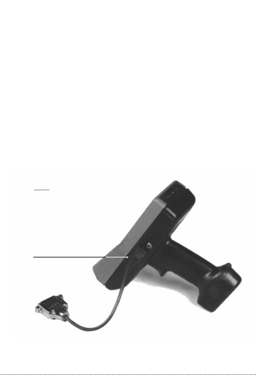
6. Gently slip the connector on the cable into
7. Connect the other end of the adapter cable to
8. Connect the remaining end of the accessory
9. Turn on the PTC and then turn on the device
FIGURE 2
Connecting a cable
the accessory connector until the tab on the
cable’s connector clicks into place. See Figure 2.
the accessory or to one of the connectors on
the accessory cable . M a k e sure the connectors line up correc tly, wide edge to wide edge,
and you are connecting a male connector to a
female connector.
cable, if used, to the co rr ect connector on the
computer or accessory. Make sure the connector on the cable and the connector on the
computer or accessory are line d up pr op er ly.
it is connected to.
PLUG THE ADAPTER CABLE’S
MODULAR CONNECTOR INTO THE
PTC’S ACCESSO RY CONNECTOR
31
Page 34

10. Follow the instructions for your appl ic ation
program to communicate.
©
Disconnecting cables
Equipment req uired:
A pen or small screwdriver
•
Always disconnect connectors by pulling them
directly away from each other. Do not pull at an
angle. Do not use a rocking or twisting motion
when pulling two connectors apart.
CAUTION! When removing a cable from the
PTC or another device, gra s p th e ca ble connector head to remove the cable. Pulling on
the cable can break the wiring from the cable
connector.
1. Press the ON/OFF key on the PTC’s key-
board to turn off the PTC.
2. Turn off the device the PTC is connected to.
3. Use the tip of a pen or small screwdriver to
press down the tab on the adapter cable’s
connector; then pull the cable out of the
accessory connector on the PTC’s left side.
4. Insert the rubber plug into the accessory
connector.
5. Disconnect the PTC’s adapter cable from the
accessory or accessory cable.
6. If necessary, disconnect the accessory cable
from the other com puter or accessory.
32
Page 35

©
Connecting to the optional communication cradle
See the manual provided with the SC-960X or
MC-960X communication cradle for instructions
on how to connect the PTC-960X.
33
Page 36

ÄÄ
canning
S
bar-code labels
The PTC-960X can be programmed to automatically recognize, read, and discriminate between
up to ten bar-code types.
The bar-code types your PTC-960X can read depend on your PTC’ s appl ication program. See the
instructions provided by your organization for
specific information and Appendix A for a list of
the bar-code types your PTC can be programmed
to read.
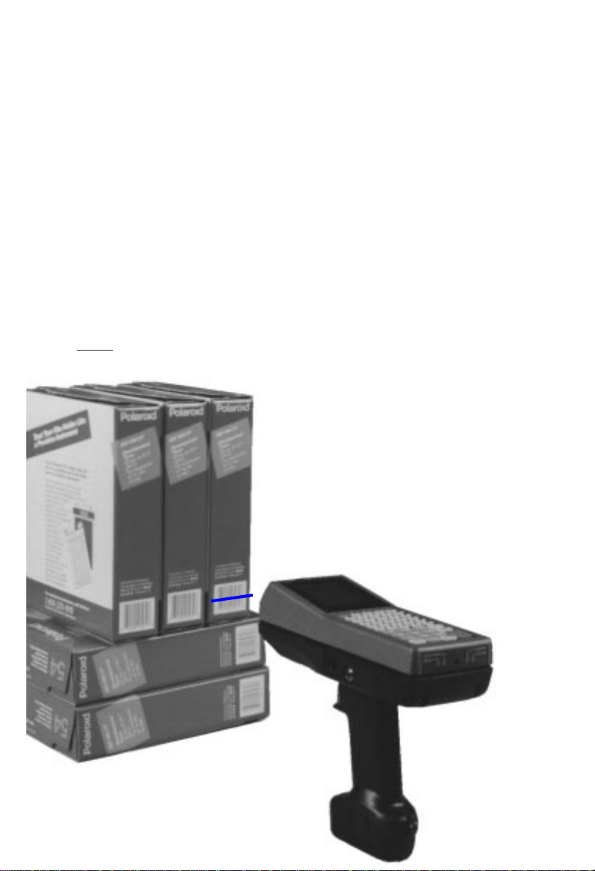
Follow this proced ure to scan bar-code labels.
1. Point the PTC-960X at the label to be
scanned. The scanner can be at an angle
to the label (see Figure 3). The maximum
distance from the window on the nose of the
PTC to the label de pends on whether you r
PTC is equipped with a short-range or longrange bar-code scanner and on the size of the
label being scanned.
See the instructions or manual provided
by your organizati on fo r the recommended
scanning distance.
2. Press the trigger on the PTC’s handle to start
scanning. The red Scan LED on the rear face
of the PTC lights.
If your PTC is equipped with the aiming dot
option, the laser proje ct s a red aiming dot
on the bar code you are pointing the PTC
34
Page 37
toward. Quickly center the aiming dot over
the bar code. Keep pressing the trigger, and
the laser begins scanning the bar code.
3. Watch the line of light m ade by the scanner
as it scans the bar code. The line must pass
over all of the bars on the label for the bar
code to be read.
4. If the scan has been successful, the green
Good Scan LED on the rear face of the PTC
blinks once, and you should hear a beep. The
LED does not light if the scan has not been
successful.
FIGURE 3
Scanning a bar-code
35
Page 38

ÄÄ
M
©
©
aintaining
the PTC-960X
Operating conditions
Although the PTC-960X is specially sealed to
resist dust, dirt, an d moi stu re, it should not be
used in excessively dirty or moist environments.
It can be operated at temperature s betwe en 32
and 104 degrees F (0 and 40 degrees C).
Handling the PTC-960X
The following information will help to ensure
you receive safe, reliable, and trouble-free service from your PTC-960X.
Do not stare into the laser beam.
•
Do not point the scanner at anyone’s eyes.
•
You could cause permanent eye damage.
Do not open the PTC’s case. Only a trained
•
technician can service the parts inside the
PTC.
If you store a PTC-960X in below-freezing
•
temperatures for more than 1 hour, do not
charge the battery pa ck until it warms up to
room temperature. Charging a cold nickelcadmium battery pack ca n damage it.
Make sure the PTC is off before you connect
•
or remove any cables or accessories or replace the battery pack.
36
Page 39

Make sure all accessories connected by cable
•
are connected correc tly and the correct cables
are used.
Use only Telxon-app ro v ed battery packs and
•
accessories. Do not attempt to connect any
electrical device th a t is not part of your PTC960X system to the PTC.
Protect the PTC from excessive heat, co ld,
•
moisture, and harsh, dirty environments.
Do not insert anything other than Telxon-
•
approved cables into the accessory connect or
on the PTC’s left side.
Be careful not to short together any of the
•
metal contacts on the PTC’s nose. Do not
allow the contacts to touch metal or other
electrically co nductive material.
Do not remove any rubber or plastic plugs on
•
the PTC’s case.
©
Storing the PTC-960X
Do not store the PTC-960X in temperatures
•
below -40 degrees F (-40 degrees C) or above
158 degrees F (70 degrees C).
Do not store the PTC-960X in a damp or
•
humid environment.
Use the following procedure to store the
PTC-960X.
1. Transfer any data stored in the PTC to a host
computer or another PTC or print the dat a.
See the manual or instructions for your
organization’ s application program for
directions.
37
Page 40

2. Make sure you have a copy of any programs
stored in the PTC.
3. Disconnect all accessories from the PTC.
4. Recharge or replace the PTC’s battery pack.
5. Pack the PTC in the original packing mate-
rial or in a padded box and put the PTC in a
safe place, away from dust, dirt, humidity,
and excessive cold.
©
Cleaning the PTC-960X
Equipment req uired:
A soft, lint-free cloth
•
A nonabrasive cleaner
•
To clean the PTC-960X, slightly moisten a soft,
clean, lint-free cloth with a mild, nonabrasive
cleaner and wipe the outside surfaces. Do not
use a paper towel.
CAUTION! Do not soak the cloth used to
clean the PTC and do not spray or po ur
cleaning liquids dire ctly onto the PTC.
If the PTC-960X becomes extremely dirty or if
liquids, dirt, or other foreign materials get
inside the case, contact your Telxon service
representative.
©
Servicing the PTC-960X
Do not attempt to service the PTC. Only a
trained Telxon technician may service the PTC.
Follow the procedure set up by your or ganizat io n
to have the PTC serviced properly.
38
Page 41
ÄÄ
eplacing the
R
battery pack
Equipment req uired:
A charged replacement nickel-cadmium
•
battery pack
©
Removing the battery pack
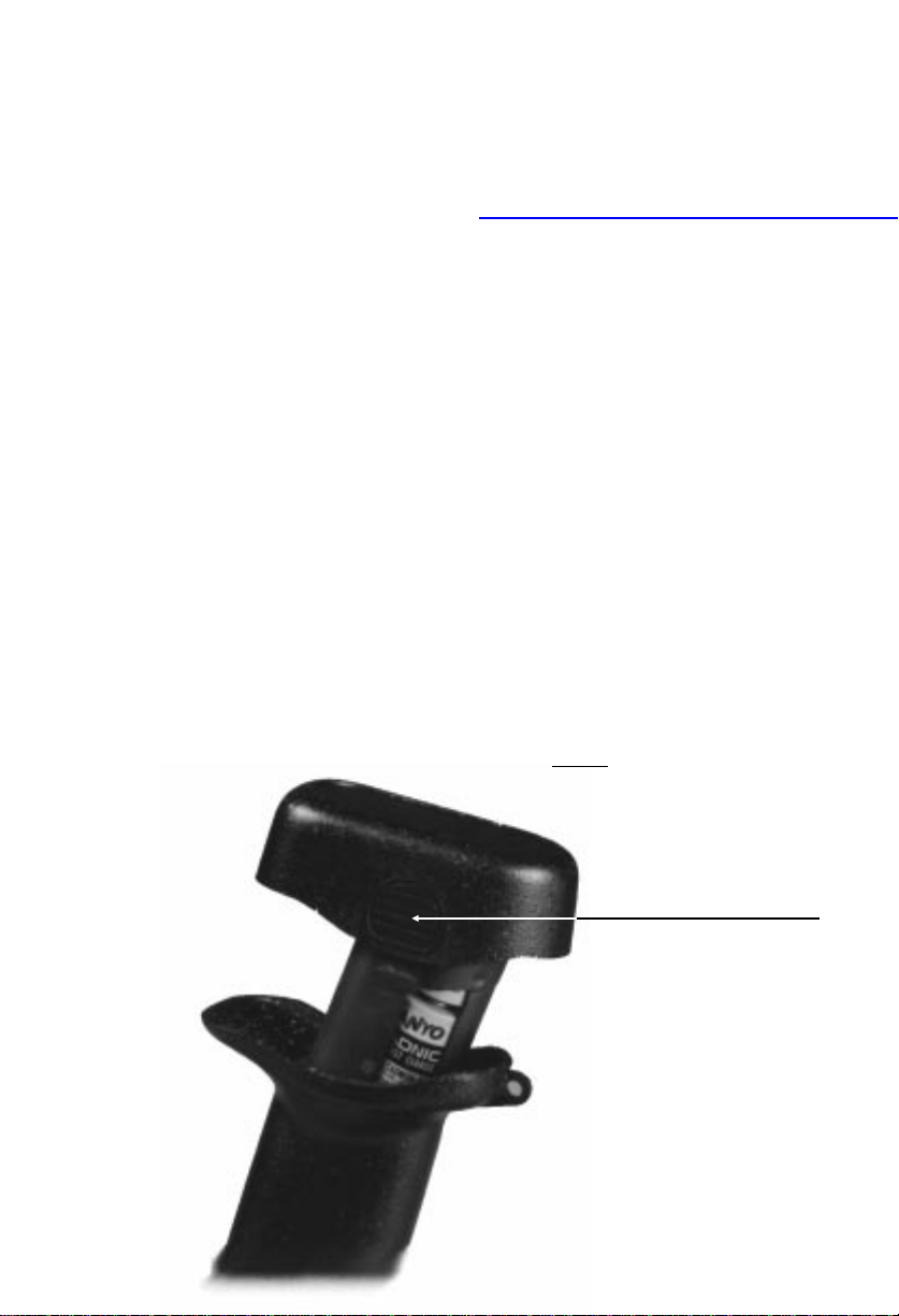
1. Press the ON/OFF key on the PTC’s keyboard to turn the PTC off.
2. With your thumb and index finger, press and
hold in the release buttons on both sides of
the handle end cap (see Figure 4); then pull
FIGURE 4
Removing the battery pack
RELEASE BUTTON (ONE ON EACH SIDE)
39
Page 42

the end cap and th e attached bat tery pack
out of the handle.
3. Re fer to page 10 for instructions on properly
disposing of your nickel-cadmium battery
pack.
©
Installing a new batte ry pack
1. Ma ke sur e th e PTC is off.
2. Li n e u p th e end cap/battery pa ck with the
opening in the handle. The curved sides of
the end cap allow th e battery pack to be installed in only one way.
3. Slide the end cap/battery pack into the han-
dle until the end cap presses against the
body of the handle and the release buttons
snap into place.
4. Pu l l on th e end cap to make sure it is locked
into place.
40
Page 43

ÄÄ
rogramming
P
the flash EPROM
The application program instructions for your
PTC-960X are stored in an electronic component
inside the PTC called a flash EPROM. This is a
type of read-only memory, but unlike standard
EPROMs, flash EPROMs can be erased and reprogrammed while they are inside the PTC. This
allows you to update your application pr ogr am
quickly and easily.
To write over existing pro g ra ms on the PTC’s
application flash EPROM, you must connect
your PTC to an MS-DOS-based personal computer and then run the FLASHPC.EXE utility to
download the special file (ROM image file) containing the new application.
©
Before you begin
Make sure the PTC’s battery pack is fully
charged. If the battery pack runs low, the reprogramming process will abort. You will lose the
application program already in the PTC.
The following procedure ass umes
you are familiar with operating an MS-
•
DOS-based personal computer,
you have read the “Communicatio n and
•
connections” section on page 29,
41
Page 44

you will connect the PTC’s download
•
cable to the person al computer’s COM1
serial port,
you will use the default settings for the
•
FLASHPC.EXE utility, and
you will run FLASHPC.EXE in interac-
•
tive mode.
If your situation differs from this, refer to th e
Guide to the FLASH Utilities (TCAL or MS-DOS
Version), part number 16541-000.
Equipment req uired
A personal computer running the
•
MS-DOS operating system
A 9-pin or 25-pin PTC adapter cable (see
•
Appendix B for the correct part number
and Appendix C for the cable diagram)
A 9-pin or 25-pin download cable (see
•
Appendix B for the correct part number
and Appendix C for the cable diagram)
A diskette containing the FLASHPC.EXE
•
utility for your PTC’s operating sys t em,
either TCAL or the RAMSaver version of
MS-DOS (Optionally, FLASHPC.EXE can
be permanently stored on your PC’s hard
disk drive.)
A diskette containing the ROM image file
•
(for your PTC’s operating system) th a t
will replace the application (ARC image
file) on your PTC (Optionally, this fi le can
be stored on your PC’s hard disk drive.)
42
Page 45

©
Procedure
1. Co n n ec t the PTC to the PC’s COM1 serial
communication port using the appropriate
adapter cable and download cable. If you
connect to the COM2 port, you must change
the comm port setting in the FLASHPC.EXE
utility in Step 8.
2. Switch to the disk drive containing the
FLASHPC.EXE utility.
If FLASHPC.EXE is on a floppy diskette,
•
insert the diskette into the PC’s floppy
disk drive A. Sw it ch to this drive by
typing A: and then pressing ENTER.
If FLASHPC.EXE is on the PC’s hard
•
disk, switch to the drive and directory
FLASHPC.EXE is on.
3. Run FLASHPC.EXE.
If you are reprogramming a single PTC,
•
type FLASHPC and then press ENTER.
If you are reprogramming a number of
•
PTCs, type FLASHPC -m and then press
ENTER.
4. The PC shows the following prompt:
Telxon Flash Loader (Version X.X)
Enter the ARC image filename (return if none):
=
Enter the RF image filename (return if none):
=
5. In the appropriate space, type in the name of
the ROM image file you want to download.
43
Page 46

Type the ROM image file name in this format:
d:\path\filename
where
d: = the disk drive the file is on
\path = the directory the file is in, if it is not
in the disk drive’s current directory
\filename = the eight- (or fewer) character
name of the file plus the file extension (the
period and three characters after it)
Press ENTER after you fill in the ARC image
file name or press ENTER by itself if you are
not entering an ARC image file name. Press
ENTER again to skip filling in the RF image
file name. The RF image file does not apply
to the PTC-960X.
6. The Main Menu displays on your PC’s
monitor scree n :
0. Quit
1. Send the image(s) to PTC
2. Select baud rate
3. Select comm port n
4. Reselect an ARC file
5. Reselect an RF file
Current file selection(s):
ARC =
RF =
Enter [0 - 5]:
7. Change the baud rate, if necessary.
The default baud rate is “autobaud,” which
means the PC starts communicating at
38,400 baud and slows down, if necessary,
until it connec ts with the PTC. This is the
default setting and should be used if possible.
44
Page 47

To change the baud rate or to reset it to “autobaud,” type 2 and then press ENTER at the
Main Menu.
The following screen displays on your PC’s
monitor:
Select the desired baud rate:
0. Quit
1. 9600 Baud
2. 19.2 K Baud
3. 38.4 K Baud
4. Autobaud (default)
Enter [0, 1, 2, 3, or 4]:
8. Change the communication port, if necessary.
Choose this option from the Main Menu only
if you have connected the download cable to
your PC’s COM2 serial port instead of to
COM1. To change the port, type 3 at the
Main Menu and press ENTER. The program
will toggle between COM1 and COM2 every
time you choose this op tion.
9. Change the ROM image file names, if
necessary.
Select option 4 on the Main Menu to change
the ARC (application) file name you specified
earlier. Your PC prompts you for the new
ROM image file name. Type in the new path
and file name and press ENTER.
To leave this screen without changing the file
name, press the ESC key.
To remove a file name from a list of ROM image files, press ENTER at the pro mpt. The
program verifies that you want to omit this
file before returning to the Main Menu.
45
Page 48

10. Select option 1 on the Main Menu, “Send th e
image(s) to PTC,” to compress th e image files
for downloadi n g .
Your PC displays status messages for each
file being compressed.
An error occurs if the PC does n ot hav e sufficient memory to compress the file or if the
specified file is too large to fit on the flash
EPROM. If an error occurs, the PC displays a
message and returns to the Mai n Men u .
When compression is co mplete, the following
message displays:
Done with all the compressions
Prepare the PTC for downloading
Press any key to start sending
Note: Do not press any key on the PC’s keyboard at this time.
CAUTION! Before proceeding, make sure the
PTC’s battery pack is fully charged.
11. If your PTC is using the TCAL operating sys-
tem, put the PTC in programming mode by
holding down the PTC’s A key until the PTC
beeps three times. When the PTC is in programming mode, the PTC will sound one long
beep followed by short repeating beeps.
If your PTC is using the MS-DOS/RAMSaver
operating system, run the FLASH.E X E program on your PTC.
At the prompt on your PTC screen, type
FLASH and press ENTER. The following
Menu displays on the PTC’s screen:
FLASH - Ver 1.1
0: System ctrl
46
Page 49

1: User ctrl
2: Exit
Type 0 to put the FLASH.EXE program in
system control mode. System co n trol mode
returns control of th e fla sh EPROM programming to your PC.
The following prompt displays on your PTC
screen:
Do you wish to
program the
flash ROM now?
(Y/N):
Type Y and press ENTER.
Note: The FLASHPC.EXE program runs
on your personal comput er, and the
FLASH.EXE program runs on your PTC
during this process.
12. Press any key on the PC’s keyboard to begin
downloading and reprogramming.
If you wish to abort the process, press the
ESC key on the PC. The FLASHPC.EXE
program returns to the Main Menu.
Before downloading begins, the PC displays
the following messa g e:
Establishing a connection...
The PC then displays status windows that
describe the current s tage of downloading
(“Erasing flash ROM,” “Programming,” and
so on).
FLASHPC.EXE then erases and repr ogr ams
the flash EPROM. When the process is complete, the PTC sounds one long beep and then
47
Page 50

turns itself off. The FLASHPC.EXE program
on the PC returns to the Main Menu.
If reprogramming is not completed successfully, refer to the Guide to the FLASH
Utilities (TCAL or MS-D OS Version) for more
information.
48
Page 51

ÄÄ
roubleshooting
T
©
If the PTC does not turn on,
charge or replace the battery pack and
•
if the PTC still does not operate, follow your
•
organization’s procedure to have the PTC
serviced.
©
If the bar-code scanner does not read a label,
move the PTC-960X closer to or farther away
•
from the bar-code label. You may not be scanning at the correct distance,
change the angle of the PTC-960X to the bar-
•
code label. The PTC may be too far above or
below the bar-code label or too far to the side
of the bar code t o sca n properly,
clean the scanner lens on the nose of the PTC,
•
point the scanner at a blank surface and
•
press the scanner trigger. Look for the scanning line that appears on the blank surface
when the scanner is operating. If no scanning
line appears, follow your organization’s procedure to have the PTC serviced, and
make sure the bar-code label you are trying
•
to scan is one of the bar-code types your
scanner has been programmed to recognize.
49
Page 52

©
If you experience any other problems with your
PTC-960X,
notify your Telxon servic e representative or
•
contact th e T elxon Customer Su pport Center
•
at 1-800-800-8010.
50
Page 53

ÄÄ
ppendix A
A
©
Specifications
Physical
Length: 8.3 in/21.1 cm
Width: 3.5 in/8.9 cm
Height: 2.1 in/5.3 cm
Weight: Approximately 2.1 lb/1 kg
Operating 32 to 104 degrees Fahrenheit
temperature: (0 to 40 degrees Celsius)
Storage -40 to 158 degrees Fahrenheit
temperature: -40 to 70 degrees Celsius
(8 in/20.3 cm at handle)
Operating
humidity: 0-95% noncondensing
Electrical
Battery pack 1400-mA/hr rechargeable
nickel-cadmium battery pack
standard
800-mA/hr rechargeable
nickel-cadmium battery pack
optional
Charger: Provides 18 VDC @ 800 mA
51
Page 54

Bar-code types supported
The PTC-960X can be programmed to read and
automatically discriminate among up to ten of
the following bar-code types. See the information
provided by your organization for the specific
bar-code types your PTC-960X is programmed to
read.
Plessey—Regular
Plessey—Alpha
Plessey—ISBN
Plessey—Pure
Plessey—Sainesbury
UPC—A & E
UPC—EAN-8 & EAN-13
UPC—A, E, EAN-8, EAN-13
Codabar
Code 39
Code 2 of 5—I, D, & Industrial
Code 2 of 5—Discrete
Code 2 of 5—Interleaved
Code 2 of 5—Industrial
Code 2 of 5—Matrix
Code 11
Code 128
Code 93
Ames Code
AS-10
Code 16k (two dimensional)
Other bar-code types may be available. See your
Telxon representative for more information.
52
Page 55

Communication
Data communications Full duplex, 300 to 19.2 K
via accessory co nnec tor: bits per second (bps )
53
Page 56

ÄÄ
ppendix B
A
©
Accessory part numbers
The following table contains part numbers for
ordering PTC-960X accessory hardware.
TABLE 1
Accessor y part numbers
Item Part number
PTC-960X
Chargers
Battery charger
PTC-960X Fast Battery Charger
without cycling
with cycling
Batteries
Battery pack
1400 mA/hr
800 mA/hr
Straps
Wrist strap
Ring wrist strap
16670-000
12176-004
16799-000
16799-001
16705-000
16742-000
14997-000
15025-000
54
Page 57

Item Part number
Cables
RJ-41-to-RS-232 25-pin adapter cable
RJ-41-to-RS-232 9-pin adapter cable
RJ-41-to-RS-232 9-pin adapter cable
PTC-to-1/2 duplex modem cable
PTC-to-full duplex modem cable
PTC-to-host (DTE) cable
Cloning cable, RJ-41-to-RJ-41
PTC-to-IBM PC/AT download cable
PTC-to-IBM PC/XT download cable
Manuals
Guide to the FLASH Utilities (TCAL or
MS-DOS Version)
Guide to Maintaining NiCd Batteries
Guide to the SC-960X
Guide to the MC-960X
15109-001
15508-000†
15508-001†
10124-0X1*
10124-0X2*
10124-0X3*
15282-000
13656-3X0*
10582-XX0*
16541-000
16488-000
16898-000
16897-000
† Cable part number 15508-000, rather than
15508-001, is required if Telxon’s PCTCOS
is being used with TCAL. Check with your
Telxon service representative to determine
which of these two cables is the correct one for
your application.
* The first digit of th e last three numbers of
these part numbers indi cat es the connector
type. The second di g it indicates the cable
length. Contact your Telxon representative
for the correct part number for your application. These cables must be us ed with the
RJ-41-to-RS-232 25-pin adapter cable, part
number 15109-001.
55
Page 58

ÄÄ
ppendix C
A
©
Communication connections
Figures 5 through 12 provide information on
the connections used to establish and maintain
communication between the PTC-960X and
other devices.
Not all available cables are described in this
section. Check with your Telxon representative
for information on other cable configurations.
FIGURE 5
RJ-41-to-RS-232 25-pin adapter cable, P/N 15109-001
PTC-960X
RJ-41
VCC 1 9 VCC
DTR 2 20 DTR
TXD 3 2 TXD
CTS 4 5 CTS
RING 5 22 RING
DSR 6 6 DSR
RTS 7 4 RTS
RXD 8 3 RXD
GND Shield 7 GND
IBM PC/XT
DB-25
56
Page 59

FIGURE 6
RJ-41-to-RS-232 9-pin adapter cable, P/N 15508-001
†
PTC-960X
RJ-41
DTR 2 6 DSR
TXD 3 2 RXD
DSR 6 4 DTR
CTS 4 7 RTS
RTS 7 8 CTS
RXD 8 3 TXD
GND Shield 5 GND
IBM PC/A T
DB-9
57
Page 60

FIGURE 7
PTC-to-1/2 duplex modem cable, P/N 10124-0X1*
PTC-960X
TXD 2 2 TXD
RCV 3 3 RCV
DSR 6 6 DSR
DTR 20 20 DTR
RTS 4 4 RTS
CTS 5 5 CTS
RI 22 22 RI
CD 8 8 CD
SG 7 7 SG
-5 VDC 10
OUT 11
Modem/T ype I
(1/2 Duplex)
58
Page 61

FIGURE 8
PTC-to-full duplex modem cable, P/N 10124-0X2*
PTC-960X
TXD 2 2 TXD
RCV 3 3 RCV
DTR 20 20 DTR
DSR 6 6 DSR
RI 22 22 RI
CD 8 8 CD
SG 7 7 SG
RTS 4
CTS 5
-5 VDC 10
OUT 11
Modem/T ype II
(Full Duplex)
59
Page 62

FIGURE 9
PTC-to-host (DTE) cable, P/N 10124-0X3*
PTC-960X
RXD 3 2 TXD
TXD 2 3 RXD
DTR 20 6 DSR
DSR 6 20 DTR
RTS 4
CTS 5 8 CD
CD 8 5 CTS
SG 7 7 SG
Host/T ype III
(Full or 1/2
Duplex)
4RTS
OUT 11
-5 VDC 10
60
Page 63

FIGURE 10
Cloning cable, RJ-41-to-RJ-41, P/N 15282-000
PTC-960X A PTC-960X B
DTR 2 2 DTR
DSR 6 6 DSR
RTS 7 7 RTS
CTS 4 4 CTS
TXD 3 8 RXD
RXD 8 3 TXD
GND Shield Shield GND
61
Page 64

FIGURE 11
PTC-to-IBM PC/AT download cable , P/N 13656-3X0*
PTC-960X
IBM PC/A T
Male
TXD 2 2 RXD
RXD 3 3 TXD
CTS 5 4 DTR
GND 7 5 GND
RTS 4 6 DSR
DSR 6 7 RTS
DTR 20 8 CTS
-5 VDC 10 9 RI
OUT 11 1 CD
62
Page 65

FIGURE 12
PTC-to-IBM PC/XT download cable, P/N 10582-XX0*
PTC-960X
Male
TXD 2 3 RXD
RXD 3 2 TXD
RTS 4 6 DSR
CTS 5 20 DTR
DSR 6 4 RTS
GND 7 7 GND
DTR 20 5 CTS
-5 VDC 10
OUT 11
IBM PC/XT
Female (0 00)/
Male (110)
63
Page 66

ÄÄ
ppendix D
A
©
LED status indicators
The following table lists and explains each of the
LED status indicators on the PTC-960X’s re ar
panel.
TABLE 2
LED status indicators
LED status
indicator
Scan This indicator glows when the scanner
Good Scan This indicator blinks once when a bar-
Charging This indicator glows when the nickel-
Low Bat This indicator glows to warn when the
Explanation
is operating and is scanning a bar code.
code label has been scanned and
decoded successfully. It will not light if
the scan has not been successful.
cadmium battery pack is being
recharged.
battery pack is running out of power.
Stop what you are doing, save the data,
and recharge or replace the PTC’s
battery pack immediately.
64
Page 67

ÄÄ
lossary
G
alphanumeric
application
autodiscriminate
bar code
bar-code scan ner
CD
Describes a character set that contains letters,
numbers, and symbols such as punctuation
marks.
A PC, mainframe, or PTC program that is
designed to perform a specific task for a user.
Examples include route accounting, payroll,
price lookup, shipping, and inventory control.
The PTC’s ability to automatically recognize
and read more than one type of bar code.
A series of vertical bars and spaces used to encode
numeric or alphanumeric information. Bar codes
are designed to be read by electronic means such
as bar-code readers or laser scanners.
An electrical device that recognizes and deciphers bar-code labels. When the reader passes
over the bar code, it converts the bar code into
electronic signals representing data. The PTC
can then enter this data into files in its memory.
Carrier detect signal. CD indicates that the
modem is receiving a signal from the remote
modem.
character
cloning
CTS
A letter, number, or symbol.
The process of copying a program or data files
from one PTC directly to another.
Clear-to-send signal. CTS indicates that the line
between a modem and a terminal device is clear
for transmission. CTS typically follows a raised
request-to-send (RTS) signal.
65
Page 68

data
communication
The transport of encoded information from one
point to another.
DCE
display
DSR
DTE
DTR
flash EPROM
function key
Data communications equipment. A device
that controls and converts incoming data or
communication, for example, a modem.
The LCD or LED pa ne l on a PTC. A PTC’ s d isplay shows data, prompts, and error messages.
Data set ready signal. The modem sends DSR to
the attached device to indicate that the modem
is connected, on, and ready.
Data terminal equipment. A device comprising
the data source, for example, the host computer.
Data terminal ready signal. The signal sent by
the terminal device to the modem to indicate
that the terminal is ready for transmission.
A flash EPROM is an electr onic component used
to store the PTC’s operating system, RF, and application programs. Unlike a standard EPROM,
the flash EPROM may be erased and reprogrammed without being removed from the PTC.
A key on the PTC’s keyboard that is defined by
an application to perform a specific task. When
pressed, a function key executes a certain function (for example, ENTER, SEND, ON/OFF).
hardware
host computer
keyboard overlay
LCD
LED
Equipment used in conjunction with programs
or data communication. Compare with
A personal computer or mainframe that receives
and processes data from remote PTCs.
The plastic label that lies on top of the PTC keyboard, identifying the function key definitions.
Liquid crystal display.
Light-emitting diode.
software.
66
Page 69

modem
Modulator-demodulator . A communication
device that converts serial digital data from
a transmitting device to a signal suitable for
transmission over a telephone line and then
reconverts the signal to serial digital data for
the receiving device.
MS-DOS
one-way
communication
PCTCOS
prompt
PTC
RAM
RAMSaver
Microsoft Disk Operating System.
Transport of information from one device to
another without interruption. In one-way
communication, the receiving device cannot
respond directly to the sending device.
A file download utility program.
Words or symbols shown on the PTC’s or PC’s
display to guide the operator through the steps
of an application. Prompts are defined in the
application program.
Portable Tele-T r ansaction Computer. A programmable, battery-powered, hand-held device used
to collect, store, and transmit data.
Random access memory. In a PTC, RAM chips
store the program’s files and data entered by
the operator.
Telxon’s version of Microsoft’s MS-DOS 3.2
that has been modified to perform MS-DOS
functions on a PTC.
RI
RS-232
RTS
Ring indicate signal. RI alerts a modem to a call
waiting on the attached telephone line.
An Electronic Industries Association (EIA)
standard that defines the connector, connector
pins, and signals used to transfer data serially
from one device to another.
Request-to-send signal. RTS initiates the data
transmission sequence on a communication line
between a modem and a terminal device.
67
Page 70

RXD
Receive data signal. RXD indicates that a
device is currently receiving data.
signals
software
TCAL
two-way
communication
TXD
Electronic impulses that transmit data from one
device to another.
A stored program or set of programs that is
loaded into RAM for execution. Compare with
hardware.
Telxon Common Application Language. Telxon’s
proprietary programming language for Portable
Tele-Transaction Computers (PTCs).
Exchange of information between two devices.
After each block of data, the receiving device
sends a positive or negative acknowledgment to
the sending device.
Transmit data signal. TXD indicates that a
device is currently transmitting data.
68
Page 71

ÄÄ
ndex
I
A
Accessories
connecting, 17, 23, 29-31
part numbers, 54
Automatic off, 25
Automatic return at on, 25
B
Backlight, 25-26
Bar code, 13, 17
types supported, 52
Bar-code label
scanning, 34-35
Bar-code scanner, 17
not reading, 49
operation, 17, 34-35
trigger, 17
Battery backup, 26
Battery charger, 14, 15-16, 19
Battery compartment, 19
closing, 40
opening, 39
Battery pack, 14, 20, 39-40
charging, 15-16
disposing of, 10
installing, 15, 40
removing, 39-40
replacing, 39-40
Beeper, 26
C
Cables, 14
adapter, 17, 23, 29-32
connecting, 29-32
diagrams, 56-63
disconnecting, 32
part numbers, 54-55, 56-63
RJ-41-to-RS-232, 17, 23, 29-32
Cautions
cleaning the PTC, 38
disconnecting cables, 32
joining connectors, 30
storing the PTC, 26
Charger connector, 19
Clock, 27
Communication, 13, 27, 29-33
connections, 29-33
contacts, 19
Communication cradle,
13, 19, 33
Connectors
accessory, 17
charger, 19
communication contacts, 19
RJ-41, 17, 23, 29-32
D
Damage, 14
Data
communicating, 13
entering, 13
Display, 19-20
contrast, 27
69
Page 72

E
M
Electrical specifications, 51
End cap/battery pack
assembly, 20, 39-40
EPROM, 13, 20-21
programming, 13, 41-48
F
FCC
statement, 8
Features, 25-28
Flash EPROM, 13, 20-21
programming, 13, 41-48
H
Handle, 21
K
Keyboard, 21-22
Keyboard overlay, 22
Keys
data, 21
ENTER/YES, 22
function, 21
ON/OFF, 22
SHIFT, 22
Maintenance, 36-38
cleaning, 38
Memory, 28
N
Nickel-cadmium battery pack,
14, 20, 39-40
charging, 15-16
disposing of, 10
installing, 15, 40
removing, 39-40
replacing, 39-40
O
Operation
bar-code scanner, 34-35
checking, 16
conditions, 36
P
Physical specifications, 51
PTC-960X
handling, 36-37
not turning on, 49
operating conditions, 36
overview, 12-13
parts, 17-24
L
LEDs, 23-24, 64
Charging, 23, 64
Good Scan, 23, 64
Low Bat, 24, 64
Scan, 24, 64
Liquid crystal display (LCD),
20
S
Safety information, 9-10
bar-code scanner, 9-10
disposing of nickel-cadmium
batteries, 10
70
Page 73

Scanner
operation, 34-35
safety, 9-10
trigger, 17
Scanning, 17, 34-35
Scope of manual, 11
Service, 38
Specifications
bar-code types supporte d, 52
communication, 53
electrical, 51
physical, 51
Status indicators, 23-24, 64
Storage, 37-38
T
Troubleshooting, 49-50
U
Unpacking, 14
W
Wrist strap, 24
71
Page 74

Telxon Corporation/3330 West Market Street, Akron, Ohio 44334/216-867-3700/800-800-8001
Part No. 16670-701-01 Printed in U.S.A.
 Loading...