

Page 1

PTC-2124
User’s
Guide
Document Number: 30833-000-002
Page 2

Chapter 3 Configuring TN-3270/5250
Page 3

PTC-2124
User’s Guide
Document Number: 30833-000-002
Release Date: November 2000
Page 4

Chapter 3 Configuring TN-3270/5250
Symbol is a registered trademark of Symbol Technologies, In c.
Windows 95 and Microsoft are r egistered trademarks
of the Microsoft Corporation.
All other product or trade references appearing in this manual are re gistered
trademarks of their respective owners.
The information in this manual is subjectto change without notice.
Symbol Technologies shall not be liable for technical or editorial omissions or
mistakes in this manual. Nor shall it be liable for in cidental or consequential
damages resulting from the use of the information contained in this manual.
This manual is copyrighted. No part of this manual may be photocopied or
reproduced in any form without the prior written consent of Symbol.
Technical Writer: Norm Walters
© Copyright 2000 Symbol Technologies, Inc.
All rights reserved.
Page 5

Table of Contents
Introduction..................................................................................... ix
This Guide’s Purpose and Scope..................................................... ix
Contacting Symbol's Product Support Center............................... ix
Chapter 1 Regulations.................................................................. 1
General regulations......................................................................... 1
FCC statement............................................................................. 1
DOC statement............................................................................. 1
89/336/EEC compatibility statement.......................................... 2
73/23/EEC directive statement ................................................... 2
Spread s pectrum radio regulations................................................ 2
FCC regulations........................................................................... 2
DOC statement............................................................................. 2
ETSI compliance statement ........................................................ 3
DataTAC radio regulations............................................................. 3
Mobitex radio regulations............................................................... 3
Chapter 2 Safety i nformation ..................................................... 5
Using and disposing of lithium-ion batteries................................. 5
Disposing of nickel-cadmium batteries.......................................... 5
PTC containing a radio................................................................... 6
PTC having a laser scanner module............................................... 6
Chapter 3 Scope of the manual................................................... 7
Document conventions.................................................................... 7
Warnings.......................................................................................... 7
Cautions........................................................................................... 7
Notes................................................................................................ 7
Related publications........................................................................ 8
Chapter 4 Overview of the PTC-2124........................................ 9
Processor.......................................................................................... 9
Operating system/environment ...................................................... 10
Memory............................................................................................ 10
ROM .............................................................................................. 10
RAM.............................................................................................. 10
PTC-2124 User’s Guide iii
Page 6

Display............................................................................................. 11
Entering data................................................................................... 11
With your finger or a stylus......................................................... 11
Through an optional laser scanner module................................ 12
Via the radio................................................................................. 12
Applications..................................................................................... 12
Storing data..................................................................................... 12
Communication............................................................................... 13
Cradle connector .......................................................................... 13
IrDA port...................................................................................... 13
Radio............................................................................................. 13
Antenna........................................................................................ 14
Power ............................................................................................... 15
AC adapter (optional)................................................................... 15
Battery pack................................................................................. 15
Bridge battery .............................................................................. 16
Vehicle adapter (optional) ........................................................... 16
Other features ................................................................................. 17
Advanced power management..................................................... 17
Backlight ...................................................................................... 18
Battery power check .................................................................... 18
Clock................................................................................................. 18
Display contrast........................................................................... 19
Low-battery warning ................................................................... 19
Accessories....................................................................................... 1 9
Communication cradles ............................................................... 19
Connector pod............................................................................... 20
Chapter 5 Getting started............................................................ 21
Unpacking the PTC-2124................................................................ 21
Setting up the PTC.......................................................................... 21
Preparing the display screen and IrDA port.............................. 22
Selecting your work area............................................................. 22
Installing the battery pack.......................................................... 22
Charging the battery pack........................................................... 22
Charging the bridge battery........................................................ 23
Loading software.......................................................................... 23
Configuring the PTC.................................................................... 23
iv PTC-2124 User’s Guide
Page 7

Chapter 6 Parts .............................................................................. 25
Flash EPROM.................................................................................. 25
Stylus............................................................................................... 25
Disposable screen protectors .......................................................... 25
Chapter 7 Drive lettering and boot sequence ......................... 31
Drive lettering................................................................................. 31
Without Card and Socket Services.............................................. 31
With Card and Socket Services and DOS................................... 32
With Card and Socket Services and Windows............................ 32
Boot sequence.................................................................................. 32
Chapter 8 Operating the PTC..................................................... 33
Holding t he PTC.............................................................................. 33
Positioning the antenna.................................................................. 33
Turning on the PTC ........................................................................ 33
Turning off the PTC........................................................................ 34
Power-off cautions ........................................................................ 34
Entering information on the screen ............................................... 35
Chapter 9 Using the PCMCIA slots............................................ 37
Preparing a PCMCIA card.............................................................. 37
Data card...................................................................................... 3 7
Other PCMCIA devices................................................................ 38
Inserting a PCMCIA card or device ............................................... 38
Removing a PCMCIA card or device.............................................. 39
Chapter 10 Communicating data ............................................... 41
Communicating via radio................................................................ 4 1
Communicating using an optional PCMCIA device...................... 4 1
Using the IrDA port ........................................................................ 41
Connecting to a communication cradle.......................................... 42
Connecting to a connector pod........................................................ 42
PTC-2124 User’s Guide v
Page 8

Chapter 11 Maintaining the battery pack................................ 43
Low-battery warning....................................................................... 4 3
Operating the PTC with the AC or vehicle adapter connected..... 43
Recharging the battery pack........................................................... 43
Charging via the AC or vehicle adapter ..................................... 44
Charging via a communication cradle........................................ 4 5
Charging via a connector pod...................................................... 45
Replacing the b attery pack............................................................. 45
Removing the b attery pack .......................................................... 4 5
Installing a new battery pack...................................................... 45
Getting the mos t ou t of your battery pack..................................... 46
Maximizing operating time ......................................................... 46
Battery pack life........................................................................... 47
Battery pack care......................................................................... 47
Disposing of battery packs.............................................................. 47
Chapter 12 Maintaining the bridge battery ............................ 49
Recharging the bridge battery........................................................ 49
Conditioning the bridge battery..................................................... 50
Replacing the b ridge battery .......................................................... 5 1
Chapter 13 Maintaining the PTC-2124...................................... 53
Operating conditions....................................................................... 53
Handling the PTC........................................................................... 53
Storing/shipping the PTC ............................................................... 54
Cleaning the PTC ............................................................................ 55
Servicingthe PTC ........................................................................... 55
Disposing of the PTC ....................................................................... 55
Chapter 14 Troubleshooting........................................................ 57
General............................................................................................. 5 7
Beep codes........................................................................................ 58
Five s ets of threebeeps................................................................ 58
Five b eeps..................................................................................... 58
LED codes..................................................................................... 5 8
vi PTC-2124 User’s Guide
Page 9

Common solutions........................................................................... 58
PTC does not turn on................................................................... 58
PTC does not respond correctly to the stylus ............................. 59
PTC does not recognize the information written on the screen 5 9
PTC’s screen is slow to refresh.................................................... 59
Radio fails to establish contact.................................................... 59
Battery pack does not hold a full charge after recharging ........ 60
Laser scanner module does not read a label............................... 60
Application locks up..................................................................... 60
Getting help..................................................................................... 61
Cannot correct the problem......................................................... 61
Chapter 15 Rebooting/Resetting the PTC ................................ 63
Rebooting the PTC .......................................................................... 63
Via a warm boot ........................................................................... 6 3
From an attached keyboard......................................................... 63
Via the pop-up keyboard from the DOS prompt......................... 64
Resetting the PTC ........................................................................... 64
Appendix A ....................................................................................... 65
Specifications................................................................................... 65
Communication and I/O ............................................................... 65
Display.......................................................................................... 65
Electrical....................................................................................... 66
Environmental ............................................................................. 66
Expansion modules (optional)..................................................... 66
Memory ......................................................................................... 67
Microprocessor ............................................................................. 67
Operating system/environment................................................... 67
Physical......................................................................................... 67
Storage.......................................................................................... 67
Stylus............................................................................................ 67
Appendix B ....................................................................................... 69
Accessory part numbers.................................................................. 69
PTC-2124 User’s Guide vii
Page 10

Appendix C ....................................................................................... 71
CPU LED codes ............................................................................... 7 1
Batt LED codes ................................................................................ 72
Appendix D....................................................................................... 73
Tips on using a stylus to enter data............................................... 73
General guidelines....................................................................... 73
Appendix E ....................................................................................... 75
Connector pinouts ........................................................................... 75
Appendix F ....................................................................................... 79
Using the optional expansion modules .......................................... 79
Using the laser scanner module.................................................. 79
Supported bar codes........................................................................ 80
Appendix G....................................................................................... 81
Connecting a wire vehicle adapter to the PTC .............................. 81
Electricalinstallation.................................................................. 81
Installing the power wire............................................................. 82
Connecting to a battery with top terminals................................ 82
Connecting to a battery with side terminals.............................. 84
Connecting to the fu se panel....................................................... 86
Installing the ground wire........................................................... 87
Securing the wires ....................................................................... 87
Connecting the wire vehicle adapter to the PTC........................ 88
Glossary............................................................................................. 89
viii PTC-2124 User’s Guide
Page 11

This Guide’s Purposeand Scope
Introduction
This Guide’s Purpose and Scope
This manual was written by the Symbol Technical
Publications Group. This group is tasked with
providing technical documentation for the Symbol
PTC-2124 product line that uses the Microsoft®
Windows CE® Operating System. Ev ery effort has
been made to provide accurate and concise information
to you, our customer.
The PTC-2124 User’s Guide provides information that
allows th e user to set up and use the PTC-2124. This
manual is meant to provide information on the various
components of this product, including
• General regulations,
• Overview of the PTC-2124,
• Maintenance and trouble shooting,
• Available accessories.
This manual, h owever, does not provide instructions
on how to perform t he tasks specific to your job within
your organization. For job-specific information, refer to
the instructions provided b y your organization.
PTC-2124 User’s Guide ix
Page 12

Chapter 3 Configuring TN-3270/5250
Contacting Symbol’s Support Center
Symbol’s Support Center may be contacted to obtain
help in resolving any PTC-21 24 system problem that
you may experience.
If you have a problem running your unit or using your
equipment, contact your facility’s technical or system
support. If there is a problem with the equipment, the
system support will contact the Symbol Support
Center at 1-800-653-5350.
For additional information on Symbol’s products and
services, please visit our website at
www.symbol.com.
x PTC-2124 User’s Guide
Page 13

Chapter
Regulations
General regulations
FCC statement
This equipment h as been tested and found to comply
with the limits f or a Class A digital de vice, pursuant
to Part 15 of the Federal Communications
Commissi on (FCC) rules. These limits are designed to
provide reasonable protection against harmful
interference when the equipmentis operated in a
commercial environment. This equipment generates,
uses and can radiate radio frequency energy and, if
not installed and used in accordance with this
instruction manual, may cause harmful interference
to radio communications. Operation of this equipment
in a residential area is likely to cause harmful
interference, in which case users will be required to
correct the interference at their own ex pense.
1
DOC statement
This digital apparatus does not exceed the Class A
limits for radio noise emissions from digital appa ratus
as outlined in the Radio Interference Regulations of
the Canadian Department of Communications (DOC).
This Class A digital device meets all requirements of
the Canadian Interference-causing Equipment
Regulations.
Cet appareil numérique de Classe A respecte les
Standards Canadiens d’émissions et perturbations
éléctromagnetiques.
PTC-2124 User’s Guide 1
Page 14

Chapter 3 ConfiguringTN-3270/5250
89/336/EEC compatibility statement
! This is a Class A product. In a
domestic environment, this
product may cause radio
interference, in which case the
user may be required to take
adequate measures.
The EC c onformity mark is affixed to this equipment
to indicate that the equipment conforms to the
appropriate requirements of the Council Directive 89/
336/EEC.
73/23/EEC directive statement
The EC c onformity mark is affixed to this equipment
to indicate that the equipment conforms to the
appropriate requirements of the Council Directive 73/
23/EEC.
Spread spectrum radio regulations
If your PTC contains a direct-sequence or frequencyhopping spread spectrum radio the following
regulations apply.
FCC regulations
The PTC-2124 uses radios (transceivers) an d radio
communication in its operation. The PTC-2124 also
uses a spread spectrum radio transceiver that
qualifies for unlicensed use. The FCC ID is on a label
on the back of the unit.
DOC statement
The PTC-2124’s radi o is also approved for use in
Canada. The PTC-2124 uses a spread s p ectrum radio
transceiver that qualifies for unlicensed use. The
Canadian DOC ID is on a label on the back of the
unit.
This device complies with RSS-210 of Industry and
Science Canada. Operation is subject to the following
two conditions: (1) this device may not cause
interference, and (2) this device m u st accept any
interference, including interference that may cause
undesired operation of the device.
2 PTC-2124 User’s Guide
Page 15

DataTAC radio regulations
ETSI compliance statement
Theplug-inradiodeviceusedinthisequipmenthas
been tested and found to complywith the European
Telecommunicat ions Standard ETS 300.328. This
standard covers wide-band data transmission systems
referred to in the CEPT recommendation T /R 10.01.
DataTAC radio regulations
The PTC-2124’s internal tra nsmitter has been type
accepted in accordance with FCC CFR Title 47, Part
90. The FCC ID, Can ad ian DOC ID, or ID number for
another appr opr iate regulatory agency is on a label on
the back of the PTC.
You mus t subscribe to the DataTAC radio network
(U.S.), Bell-Mobility (Canada), or the DataT AC
system carrier in the country of operation before using
this internal radio. You will need to provide the
logical link identifier (LLI) nu mber fro m the label on
the rear of the unit for registration on the network.
See your Symbol repre sentative for information on
subscribing to the network in the country in which the
PTC will be used.
No license is required to operate this product in the
U.S. or Canada. For information on operating
regulations in other countries, see your Symbol
representative.
Mobitex radio regulations
The PTC-2124’s internal tra nsmitter has been type
accepted in accordance with FCC CFR Title 47, Part
90. The FCC ID, Can ad ian DOC ID, or ID number for
another appr opr iate regulatory agency is on a label on
the back of the PTC.
PTC-2124 User’sGuide 3
Page 16

Chapter 3 ConfiguringTN-3270/5250
You must subscribe to the Bell-South Mobile Data
radio network in the country of operation before using
this internal radio. You will need to provide the
Mobitex access number (MAN) from the label on the
rear of the unit for registration on the network. See
your Symbol representative for information on
subscribing to the network in the country in which the
PTC will be used.
No license is required to operate this product in the
U.S. or Canada. For information on operating
regulations in other countries, see your Symbol
representative.
4 PTC-2124User’sGuide
Page 17

Chapter
Safety information
Using and disposing of lithium-ion batteries
Follow these guidelines when handling the PTC’s
lithium-ion battery pack:
• Do not expose the battery pack to water, metal
objects, direct sunlight, extreme heat, or fire.
• Do not attempt to disassemble the battery pack.
• Do not handle a damaged or leaking lithium-ion
battery pack.
Lithium-ion batteries contain chemically active
materials that are hazardous to the environment;
therefore, they mu st be disposed of properly. Never
attempt to incinerate a lithium-ion battery; doing so
could cause it to explode. Symbol urges you to c ontact
the Environmental Protection Agency, the
Department of Natural Resources, a local hazardous
waste disposal agency, or the Symbol Poduct Support
Center at 1-800-653-5350 for assistance prior to
disposing of your lithium-ion batteries.
2
Disposing of nickel-cadmium batteries
The PTC’s nickel-cadmium bridge bat tery is not user
accessible; however, it contains che mically active
materials that are hazardous to the environment and
must be disposed of properly. Never attempt to
incinerate a nickel- cadmium battery; do i ng so could
cause it to explode.
PTC-2124 User’sGuide 5
Page 18

Chapter 3 ConfiguringTN-3270/5250
Do not throw away the PTC when it has reachedthe
end of its useful life. Send it to an authorized Symbol
service center for bridge battery removal and
recycling before the unit is disposed of permanently.
PTC containing a radio
This device is compliant to the ANSI C95.1 (1992)
Standard for Safety Levels with Respect to Human
Exposure to Radio Frequency Electromagnetic Fields
per FCC Docket 93-62.
PTC having a laser scanner module
$Do not stare into the scanner’s
laser beam if the protective
cover is removed. Permanent
eye damage could result.
The PTC-2124’s optional laser scanner module is a
Class II laser product. It emits a 1.0 mW beam of
laser light from the output window. No maintenance
is require d to keep this product in compliance with
U.S. Dep a rtment of Health and Human Services
(DHHS) Regulation 21 CFR Subchapter J. No contr ols
are provided f or o peration or maintenance. Laser lig ht
in excess of Class I limits is inside an internal
protective cover.
The laser safety warning label required by the DHHS
for the PTC-2124’s optional laser scanner module is
located on the scannermodule near the scanning
window.
6 PTC-2124User’sGuide
Page 19

Chapter
Scope of the manual
This manual provides general information on the
PTC-2124’s parts, features, and accessories. It also
explains how to operate and maintain the PTC.
This manual does not provide instructions on how to
perform the tasks specific to your job in your
organization. For that information, refer to the
manual or instructions provided by your supervisor.
Document conventions
The following conventions are used throughout this
manual.
Warnings
3
Warnings indicate potential bodily injury or death.
They are set off in the left-hand columns of this
manual by the follo wing symbol:
$.
Cautions
Cautions indicate potential damage to equipment.
They are set off in the left-hand columns of this
manual by the follo wing symbol:
! .
Notes
Notes pr ovide s upplementary information. They are
set off in the left-hand columns of this manual and are
not preceded by a symbol.
PTC-2124 User’sGuide 7
Page 20

Chapter 3 ConfiguringTN-3270/5250
Related publications
Refer to Appendix B for ordering
information.
The following manuals may be usefu l as you operate
the PTC:
• SC-1124/VC-1124 User’s Guide—Contains
operation and maintenance instructions for the
communication cradles that can be used with the
PTC-2124.
• CP-1124 Read-Me-First Sheet—Describes the
connector pod that can be used with a PTC-2124.
The sheet provides instructions on connecting the
pod to the PTC and on using the pod’s keyboard,
Ethernet, serial, and charger ports.
• Documentation provided with the Symbol PenBased SC400 Software Development Kit—A set of
manuals describing and providing programming
information for the software components of a PTC
with an SC400-based processor.
• PTC-2124 Softwa re Guide—Serves as a
supplement to the documentation provided with
the Symbol Pen-Based SC400 Software
Development Kit. It provides software and
programmin g information specific to the PTC-
2124.
8 PTC-2124User’sGuide
Page 21

Chapter
Overview of the PTC-2124
The PTC-2124 is a rugged, SC400-proc essor-powered,
PC-compatible,pen-based portable teletransaction
computer (PTC). It is used to collect, store, and
transmit data. Unlike personal computers, which rely
primarily on a keyboard for data entry, the PTC-2124
uses its screen as the main input device.
In general, operate your PTC by using y our finger or
the supplied stylus to select choices from menus. The
stylus may also be used to write directly on the screen
to fill in forms or c heck off boxes. The actions you take
depend on the application program your organization
has developed for its specific needs. See the manuals
or instructions that your organization provides for
details o n your application.
Through its pen operating environment, the PTC
recognizes the touches or written letters and numbers
on its screen and translates them into a form that can
be used and stored in the PTC.
4
Processor
The PTC’s 100-MHz AMD Elan SC400 microprocessor
is fully IBM PC compatible. It provides exceptional
processing speed and is designed for low power
consumption.
100 MHz is the default setting. The PTC can also be set to operate at 33 or 66 MHz to
reduce power consumption. To change the processor
speed, press the F2 key from an attached keyboard
during boot-up to access the CMOS s etup. Then select
the Advanced option and press the + or – key to s et
the speed to 33, 66, or 100 MHz.
PTC-2124 User’sGuide 9
Page 22

Chapter 3 ConfiguringTN-3270/5250
Operating system/environment
The PTC-2124 uses the MS-DOS 6.22 or Windows CE
2.12 operating system . PenRight!, a separate pen
operating environment that may run on top of the
operating system, allows the PTC to recognize touches
as well as written letters and numbers.
Memory
The PTC-2124 has two types of m e mory: read-only
memory (ROM) and r andom access memory (RAM).
ROM
The PTC-2124 comes with 512 kilobytes (KB) of readonly memory. It is used to store the PTC’sBasic
Input/Output System (BIOS).
RAM
The PTC-2124 can be ordered with 4, 20, 36, or 64
megabytes (MB) of random access memory.
RAM is used to store data that the PTC needs while it
is running. One MB of RAM is reserved for running
the operating system and your application. The
remaining RAM may be used by the pen-operating
environment or by some applications.
Refer to Chapter 15 for information
on resetting the PTC.
Refer to the section titled "Advanced
power management" on page 17 for
information on the PTC’s APM
feature.
10 PTC-2124 User’sGuide
Data stored in RAM can be e asily read, written, and
changed. It is also volatile. All data in RAM will be
lost if the PTC’s battery pack and bridge batter y run
out of power or if the PTC is rebooted or reset.
During normal operation, the PTC’s advanced power
management (APM) feature automatically saves data
in RAM and saves your p lace in the ap plication.
Page 23

Display
Display
! If left in direct sunlight for an
extended time, the display can get
hotter than its maximum operating
temperature and darken. Shade it as
much as possible from direct
sunlight
The PTC-2124 contains a 1/4 VGA, transflective,
monochrome display with an EL panel backlight.
A tr ansflective display uses reflected ambient light to
produce viewable display images. It is ide al for use in
outdoor applications. For indoor use, the PTC’s
backlight may be used to optimize the display
visibility i n low lighting or under fluorescent lights.
The PTC-2124 features a resistive touch panel
digitizer, which is mounted above the display. The
digitizer enables the PTC to recognize data entered
with a stylus. It also has a palm reject feature, which
prevents accidental activation of the unit by casual
hand or finger contact.
Entering data
Data can be en tered into the PTC-2124in a variety of
ways. You can use your finger or t he PTC’sstylusto
select options on the PTC’s screen; scan 1D bar codes
with an optional laser scanner module; or receive data
through an optional internal radio.
With your finger or a stylus
As a pen-based computer, the PTC-2124is ideal for
forms-based data gathering. Use your finger to select
menu options or the PTC’s stylus to write in the fields
of a form displayed on the PTC’s screen or to check off
items on a list. You may also have the option to
capture signatures onto electronic forms (for example,
when a delivery is made or an order is placed).
PTC-2124 User’sGuide 11
Page 24

Chapter 3 ConfiguringTN-3270/5250
Through an optional laser scanner module
A bar code is a series of vertical bars
and spaces used to encode
information in a machine-readable
form. They are used on nearly every
item in business today.
A second method of entering data is with the PTC’s
optional laser s canner module. Wh en you scan a 1D
bar code that the PTC is programmed to read, the
PTC and scanner interpret the data and store it in the
PTC’s memory. See Appendix F for instructions on
using the scanner module and for a list of supported
bar codes.
Via the radio
Refer to the section titled "Radio" on page 13 for
information on radio communication.
Applications
The Symbol Pen-Based SC 400 Software D evelopment
Kit, Symbol part numbe r SK20-0219, is available to
assist you in developing pen-based applications for
your PTC. Contact your Symbol representative for
more information.
Storing data
Data entered into the PTC can be stored in the PTC’s
RAM, on an internal solid-state compact flash hard
disk dr ive, on removable PCMCIA solid-state data
cards, or on rotating media.
In addition to storing data entered by the u ser, t he
PTC’s solid-state compact flash hard disk dr ive also
stores the DOS or WinCE operating system.
If your PTC contains a factoryinstalled LAN radio, only one PCMCIA
slot, which accepts Type II cards, is
available.
12 PTC-2124 User’sGuide
PCMCIA data cards are credit-card-sized memory
cards that are used much as floppy disks are in a
personal com puter. The PTC-2124 has two useraccessible PCMCIA slots that can accept two Type II
cards (one per slot) or one Type III card.
Page 25

Communication
Cradle connector
Communication
For more information, see the
documentation provided with the
accessory.
The PTC’s cradle connector allows direct connection to
an SC-1124 Desktop Cradle, a VC-1124 Vehicle
Cradle, or a CP-1124 Connector Pod. Each of th ese
accessories provides communication and battery pack
charging and can be connected to various e xternal
devices.
IrDA port
The IrDA 1.0 port allows the PTC to communicate via
pulses of light to an d from other IrDA-compliant
devices, such as printers and h ost systems.
Radio
The PTC can be equipped with one local area network
(LAN) radio or one wide area network (WAN) radio.
LAN radio options
• Direct-sequence spread spectrum radio.
• 2.4 GHz direct-sequence 802.11-compliant spread
spectrum radio.
• 2.4 GHz frequency-hopping 80 2.11-compliant
spread spectrum radio.
Spread spectrum radios allow the PTC to
communicate interactively in real-time with a host
computer on a radio-based local area network. They
provide secure, interference-free communication and
do not require a license for operation.
No license is required to operate a
WAN radio in the U.S. or Canada, but
you must subscribe to the
corresponding radio network (or
another DataTAC network) before
the radio can be operated.
PTC-2124 User’sGuide 13
WAN radio options
• DataTAC r adio
A DataTAC radio allows the PTC to communicate
via a wide-area DataTAC communication
network.
Page 26

Chapter 3 ConfiguringTN-3270/5250
• Mobitex radio
A wide-area network is a radio network that supports
data communications across a broad area, such as a
city, a state, or even nationwide.
A Mo bitex radio allows the PTC to communicate
via the wide-area Bell-South Mobile Da ta digital
communication network.
Your PTC’s application program
controls the radio. Refer to your
application’s manual for details on
using the radio to transmit and
receive data.
Fold the antenna against the PTC
when the unit is not in use.
The PT C uses its radio to communicate with a host
computer. Via the radio, the PTC can send data to the
host, and the host can send data and instructions to
the PTC.
Antenna
If the PTC-2124 contains an ex p a nsion modu le and a
radio, the radio antenna is located inside the
expansion module.
If the PTC contains a radio but not an expansion
module, a single external articulating 800 MHz, 900
MHz, or 2.4 GHz antenna is attached to the blank
module cover on the right side of the PTC. The
articulating antenna bends at a 90× angle at its
knuckle and rotates 360° degrees around its mounting
point. To achieve maximum signal strength for both
transmission and reception, make sure the antenna is
perpendicular to the ground, regardless of w hether
you are holding the PTC or it is installed in a
communication cradle.
14 PTC-2124 User’sGuide
Page 27

Power
AC adapter (optional)
Power
! Use only the AC adapter supplied
by Symbol with the PTC. Using any
other adapter could cause damage.
! Never leave the PTC without the
battery pack installed. Removal of
the pack will drain the bridge battery
(even with the unit suspended).
Replace the PTC’s battery pack after
500 charge cycles.
A 15 VDC, 2.7 A AC adapter provides power to
recharge the PTC’s lithium-ion battery pack and
nickel-cadmium bridge battery. The adapter connects
to the PTC’s power jack and to an electrical outlet via
an AC power cord. The adapter h as a CEE.22
connector t hat accepts a wide range of AC cords with
an input voltage between 100 and 240 VAC at
50/60 Hz.
When the AC adapter is attached to the PTC, the unit
draws its power from the electrical outlet, not from
the battery pack. As a result, the PTC may remain on
and be operated while its battery pack is being fast
charged.
Battery pack
Operating power for the PTC-2124 is provided by a
rechargeable lithium-ion batte ry pack.
The battery pack can be c harged via an AC adapter,
vehicle adapter, desktop cradle, vehicle cradle, or
connector pod.
TheamountoftimeduringwhichthePTCcan
operate on a fully charged battery pack depends on
the features used and on the length of time the PTC
spends communicating with the host computer. The
more the radio, backlight, PCMCIA slot(s), hard disk
drive, and optional expansion modules are used, the
sooner the battery pack will run out of power.
See Appendix C for more information
on the Batt LED codes.
PTC-2124 User’sGuide 15
When battery pack power is low,the PTC s ounds five
sets of three beeps, and the Batt LED glows red. If
you hear or see these warnings, promptly recharge the
battery pack.
Page 28

Chapter 3 ConfiguringTN-3270/5250
Bridge battery
! Always suspend the PTC before
removing its battery pack.
! Use only the vehicle adapter
supplied by Symbol with the PTC.
Using any other vehicle adapter
could cause damage.
Refer to Appendix B for ordering
information.
An internal rechargeable nickel-cadmium bridge
battery provides power to protect data stored in the
PTC’s RAM memory wh ile the batte ry pack is being
replaced or if it runs out of power. The bridge battery
can protect the PTC’s memory for a cumulative total
of 4 to 5 hours with the PTC suspended and the
battery pack removed. The bridge battery is
recharged automatically when the main battery pack
is recharged.
The bridge battery’s condition is checked every ti me
the PTC is resumed. If t he bridge battery power is
low, the PTC beeps five tim es, and the B att LED
blinks r ed. If you hear or see these warnings,
immediately recharge the unit for 5 hours.
Vehicle adapter (optional)
A 15 VDC, 2.7 A vehicle adapter may be used to
recharge the PTC’s lithium-ion battery pack and
nickel-cadmium bridge battery. The adapter plugs
into the PTC’s power jack and into a vehicle’s
cigarette lighter socke t or directly to a vehicle’s
battery or fuse panel.
Three vehicle ad apters are available:
• A cigarette lighter adapter for 12-volt automotive
systems.
• A wire adapter for 12-volt automotive sys te ms.
• A wire adapter for 24-volt automotive sys te ms.
When the veh icle adapter is attached to the PT C, the
unit draws its power from the vehicle’s power source,
not from the battery pack. As a result, the PTC can
remain o n and be operated while its battery pack is
being fast charged.
16 PTC-2124 User’sGuide
Page 29

Other features
Other features
Advanced power management
Reduced power state
The PTC goes into a reduced power state if it is not
used for a periodof time or if it is suspended using the
On/Off button. In the reduced po wer state, the PTC
turns off portions of its internal electronics to
conserve power.
The PTC has two stages of reduced power. The first
stage (standby) begins after approximately 1 minute
of inactivity. During this stage, the PTC’s screen goes
blank, the backlight turns off, and other subsystems
inside the PTC may slow down or turn off to conserve
power. The PTC’s CPU LED blinks red every 2
seconds to indicate that the PTC is in standby mode.
The application program running at the time is
suspended, and any data in RAM are protected.
The second stage (suspend) begins approximately 16
minutes after the PTC enters the standby mode or if
the On/Off button is pressed while the unit is
operational. This stage turns off additional hardware
elements and provides only minimal memory refresh
operations. The CPU LED blinks every 4 seconds.
The exact amount of time before the PTC goes into
either r educed power state is programmable. Consult
the PTC-2124 Software Guide for pr ogramm ing
instructions.
Resume
Refer to the PTC-2124 Software Guide
for a list of other possible wake
sources.
PTC-2124 User’sGuide 17
When the PTC is in standby mode, touching the
PTC’s screen with the stylus or pressing the On/Off
button tur ns the PTC back on and returns you to the
point at which y ou left the application.
Page 30

Chapter 3 ConfiguringTN-3270/5250
When the PTC is in suspend mode, you must press
the On/Off button to turn the PTC back on. Once
again, you are returned to the point at which you left
the application.
Backlight
The PTC’s backlight lights up the screen, making it
easy to read. The backlight can be turned on or off by
pressing the Backlight button.
To save power, the screen and back light autom a tically
turn off when there has been no activity on the screen.
The du ration of inactivity can be set by your
application program.
Battery power check
The PTC regularly checks the amount of power
remaining in the battery pack and the bridge battery.
Refer to the section titled "Lowbattery warning" on page 19 and
Chapter 11 for more information.
Before either battery is exhausted, the unit warns you
with a series of beeps. W hen you hear them, promptly
recharge the PTC’s b attery pack.
Clock
The clock can be set using the MSDOS TIME and DATE commands.
18 PTC-2124 User’sGuide
The PTC’s built-in clock keeps track of the date
(month, day, year, and day of the week) and the time
(hours, min utes, seconds, and tenths of seconds).The
clock operates continuously. How the clock is used
depends on your application program. Fo r example,
the PTC can use the clock to show the date and time
on its screen or to time-stamp a file.
If the PTC’s battery pack and bridge battery
becomefully discharged, the date and time will be lost
and have to be r e-entered.
Page 31

Display contrast
Accessories
If the screen is completely dark or
blank, press the Contrast button to
select an appropriate contrast level.
See Appendix C for more information
on the Batt LED codes.
The PTC screen’s contrast can be changed usin g the
Contrast button. Pressing th is button adjusts the
contrast in one direction, from lightest to darkest.
Once the darkest setting is reached, the contrast
wraps back to the lightest contrast level.
Low-battery warning
The PTC warns you w hen the battery pack or the
bridge battery is running ou t of power.
The battery pack is monitored constantly. If power
runs low, the PTC sounds five sets of three short
beeps with a pause between sets, and the Batt LED
glows red. When you h ear or see these warnings,
promptly save any data and recharge the PTC’s
battery pack.
The bridge battery is checked every time the PTC is
resumed. If the bridge battery is running out of
power, the PTC sounds five beeps,and t he Batt LED
blinks r ed. If you hear or see these warnings,
immediately save any data and recharge the bridge
battery.
Accessories
Communication cradles
Two communication cradles are available for use with
the PTC-2124: the SC-1124 Deskto p Cradle and the
VC-1124 Vehicle Cradle. These cradles recharge
simultaneou sly the PTC’s batte ry pack and a spare
pack and allow the PTC to communicate with a host
computer. Each cradle also provides Ethernet and
serial interfaces to external devices as well as a
keyboard connector.
PTC-2124 User’sGuide 19
Page 32

Chapter 3 ConfiguringTN-3270/5250
Connector pod
Appendix E lists the pinouts for the
CP-1124’s keyboard, Ethernet, and
serial ports.
The CP-1124 Connector Pod, which a ttaches to the
PTC’s cradleconnector, allows the PTC to be
connected to a variety of external devices, including a
keyboard, an Ethernet network, and a serial device.
The pod also contains a charger jack to recharge the
PTC’s battery pack.
20 PTC-2124 User’sGuide
Page 33

Unpacking the PTC-2124
Chapter
5
Getting started
Any additional accessories are
shipped separately.
If anything is missing or damaged,
notify your Symbol sales
representative.
Each shipping box contains
• a PTC-2124 pen-based computer,
• a lithium-ion battery pack,
• a 15 VDC, 2.7 A AC or vehicle ad apter (if ordered),
• astylus,
• a PTC-2124 Read-Me-First Sheet, and
• a PTC-2124 User’sGuide.
The following steps should be performed in unpacking
the shipping box.
1. Remove the PTC and other parts from the box.
2. Remove all packing material from the PTC. Save
the packaging in case the PTC is ever stored or
shipped to Symbol for service.
3. Check the contents of the package to make sure
you have received everything ordered.
4. Check the PTC and accessories for shipping
damage. Pay particular attention to the PTC case
and screen.
Setting up the PTC
Follow the instructions in this section to set up the
PTC for the first time.
PTC-2124 User’sGuide 21
Page 34

Chapter 3 ConfiguringTN-3270/5250
Preparing the display screen and IrDA port
! If the plastic sheets are not
removed, the PTC may not operate
properly.
The PTC-2124’s display screen and IrDA port may be
covered by a thin sheet of plastic to provide protection
during shipment. Carefully peel off these sheets
before using the PTC’s display and I rDA port.
Selecting your work area
HoldthePTCorsetitonaflatsurfaceata
comfortable height. Choose an area that is free of
• rapid changes in temperatureand humidity;
• dust, moisture, extreme heat, an d direct sunlight;
• objects that rad iate heat;
• objects that generate a strong electromagnetic
field (such as stereo speakers); and
• liquids and co rrosive chemicals.
Whether you are using the PTC or storing it, make
sure the environment is neither too hot nor too cold. If
you are comfortable, the temperature and humidity
will be suitable for the PTC.
Installing the battery pack
If the battery pack is not already installed, follow the
instructions in the section titled "Installing a new
battery p a ck " on page 45.
Charging the battery pack
! For first-time use, charge the unit
for 5 hours.
22 PTC-2124 User’sGuide
The b attery pack must be charged before you can use
the P TC. Follow the in structions in the section
"Recharging the battery pack" on page 43.
Page 35

Charging the bridge battery
SettingupthePTC
See Chapter 12 for more
information.
See your MS-DOS manuals for an
explanation of the CONFIG.SYS and
AUTOEXEC.BAT files.
The bridge battery must be charged before you can
use the PTC. Charging the main battery pack for 5
hours (as instructed in the previous section) will also
fully charge the bridge battery.
Loading software
The operating s ystem and/or the pen operating
environment a re l oaded into your PTC at the factory.
If you need to load application software, instructions
are provided in the P TC-2124 Software Guide and in
the documentation that accompanies the Symb ol Pen Based SC400 Software Development Kit. Refer to
Appendix B for ordering information.
Configuring the PTC
Your PTC is configured through the MS-DOS
config.sys an d autoexec.bat files. These files load
and execute software d evice drivers and application
programs and can be used to manage your PTC’s
memory. Th e documentation provided with the
Symbol Pen-Based SC400 Software Development Kit
contains information on configuring your PTC
through these files.
PTC-2124 User’sGuide 23
Page 36

Chapter 3 ConfiguringTN-3270/5250
24 PTC-2124 User’sGuide
Page 37

Chapter
Parts
Figures 1 through3 on the following pages show and
describe the parts of the P TC-2124. The parts listed
below are not shown in any of the figures.
Flash EPROM
Flash EPROMs are electronic chips installed inside
the PTC. In the PTC-2124, a flash EPROM holds the
boot loader. If your P TC contains a radio, a separate
flash EPROM holds the program that controls the
radio.
Flash EPR OMs can be erased and reprogrammed
while they are inside the PTC . The documentation
provided with the Sym bol Pen-Based SC400 Software
Developme nt Kit contains instructions on
reprogramming flash EPRO Ms. Refer to Appendix B
for ordering information.
6
Stylus
! D o not writ e on the P TC’s screen
with an ink pen, pencil, or marker;
using these will mar the screen.
A stylu s may be used to write directly on the PTC’s
screen. An optional stylus holder, which attachesto
the P TC, is available to hold the stylus when it is not
in use.
Disposable screen protectors
Disposable screen protectors, Symbol part number
30782-001, are available to protect the PTC's screen
from scratches and damage (e.g., fr om repeatedly
striking a soft key in an application).
PTC-2124 User’sGuide 25
Page 38
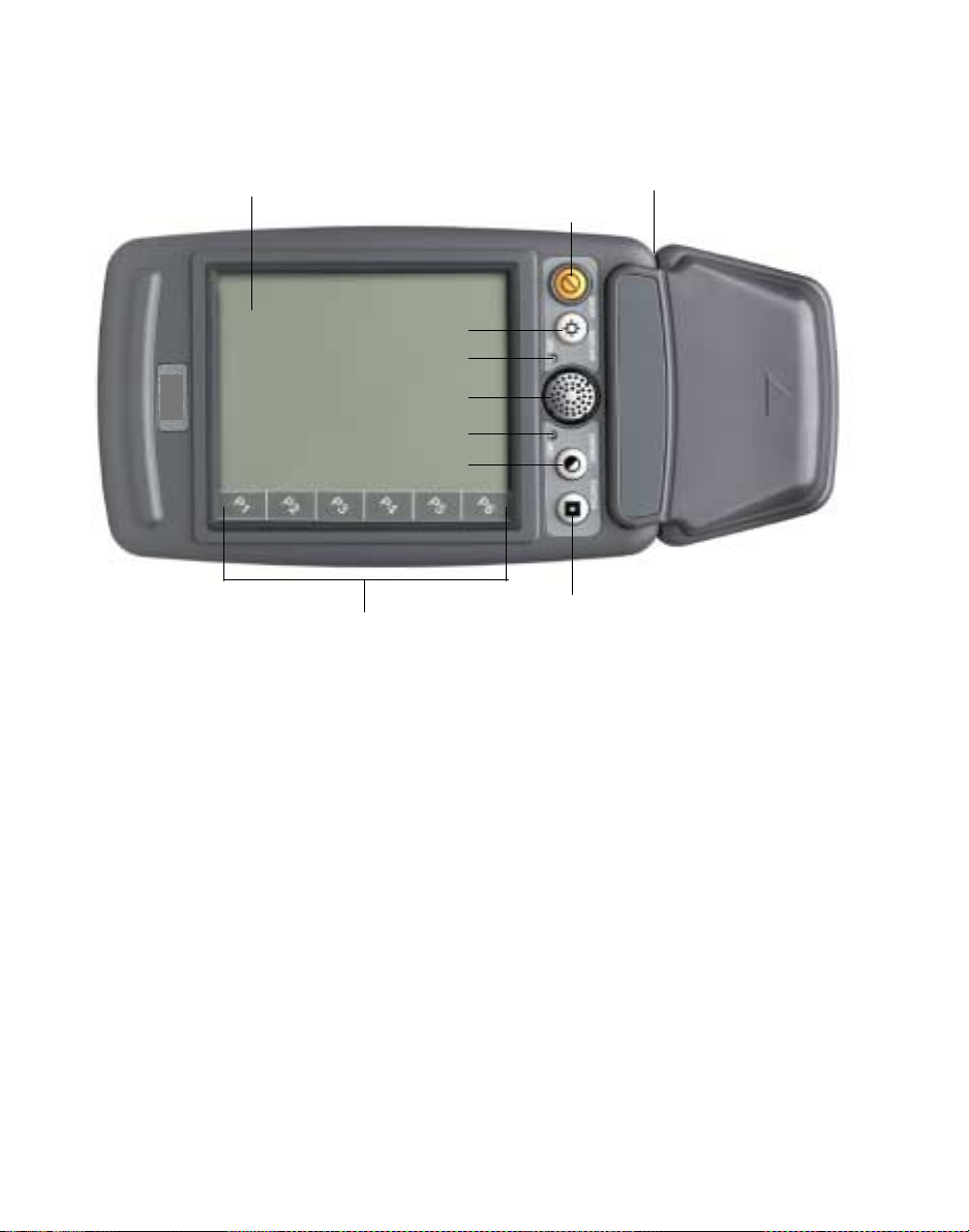
Chapter 3 ConfiguringTN-3270/5250
Figure 1. The PTC-2124(top view)
1. Display screen 3. Expansion module connector
4. Backlight button
4. Backlight button
5. CPU LED
6. Speaker
7. Batt LED
8. Contrast button
2. On/Off button
9. Icon strip
10. Function button
1. This 1/4 VGA, transflective, monochrome liquid crystal display (LCD) screen has 320 x 240 lines of resolution and features a
built-in backlight to enhance readability. The screen displays data entered into the PTC and may show prompts, error
messages, and other information.
2. Pressing the On/Off button turns on the PTC or wakes it from a reduced power state. If the PTC is awake, pressing On/Off
puts the unit into suspend mode.
3. If your PTC contains an optional expansion module (laser scanner), it will be attached to the PTC via the expansion module
connector. See Appendix E for the scanner expansion module connector pinouts. If your PTC does not have an expansion
module, the expansion module connector will be sealed with a blank expansion module cover. Figure 1 shows the PTC with
an attached laser scanner module.
4. The Backlight button turns the display’s backlight on or off.
5. This LED indicates the status of the PTC. See Appendix C for an interpretation of the CPU LED codes.
6. The speaker, located behind this grill, can be used by your application program to warn you of problems or to prompt you
26 PTC-2124 User’sGuide
Page 39

Disposable screen protectors
to take an action. For example, the PTC warns you with a series of beeps when the battery pack or bridge battery is running
out of power. Refer to the section titled "Beep codes" on p. 58 for an explanation of the standard beep codes. Other codes
may be specific to your application, which controls how the speaker is used. Your PTC can also be programmed to change
the volume of the beeps emitted by the speaker.
7. This LED indicates when the PTC’s battery pack or bridge battery is low, the charging status of the battery pack, and
whether any errors have occurred. See Appendix C for an interpretation of the Batt LED codes.
8. The Contrast button can be used to change the contrast of the PTC’s screen. Pressing the Contrast button adjusts the
contrast in one direction, from lightest to darkest and then wraps back to the lightest contrast level.
Note: If the screen is completely dark or
blank, press the Contrast button to
selectan appropriate contrast level.
9. An additional line at the bottom of the display is reserved for six icons: P1 through P6. These icons can be custom
programmed to meet the needs of your application. The
PTC-2124 Software Guide provides information on
programming the PTC’s display icons.
10. This button can be programmed via the PTC’s application to perform a specific function.
PTC-2124 User’sGuide 27
Page 40

Chapter 3 ConfiguringTN-3270/5250
Figure 2. The PTC-2124(right side view)
1. Scan trigger
(one on each side)
3. Optional laser scanner
2. IrDA port
4. Battery door
6. Hand grip
5. Battery release button
(one on each side)
1. Pressing one of the scan triggers (one on each side of the PTC) activates the PTC’s optional laser scanner module. The shape
of the scan trigger conforms to the shape of the human thumb for ease of operation. Press directly on the raised round area
of either trigger. You will hear and feel a distinctive “click” when the scanner has been activated. The CPU LED glows solid
green and the PTC beeps to indicate a successful scan.
2. This IrDA 1.0 port allows the PTC to communicate via pulses of light to and from other IrDA-compliant devices, such as
printers and host systems. See Chapter 10 for information on using the PTC’s IrDA port.
3. This optional laser scanner module allows 1D bar codes to be read, interperted, and stored in the PTC’s memory.
4. The battery door provides access to the battery compartment, which contains the PTC’s Reset button and the lithium-ion
battery pack that powers the unit.
5. Pressing these two buttons (one on each side of the PTC) allows the PTC’s battery door and battery pack to be removed.
Refer to Chapter 11 for instructions on replacing the battery pack.
6. Use the PTC’s hand grip to hold the PTC during use. The hand grip is molded to provide a secure grip. An optional
adjustable leather hand strap (shown in Figure 3) is available for use with the hand grip.
28 PTC-2124 User’sGuide
Page 41
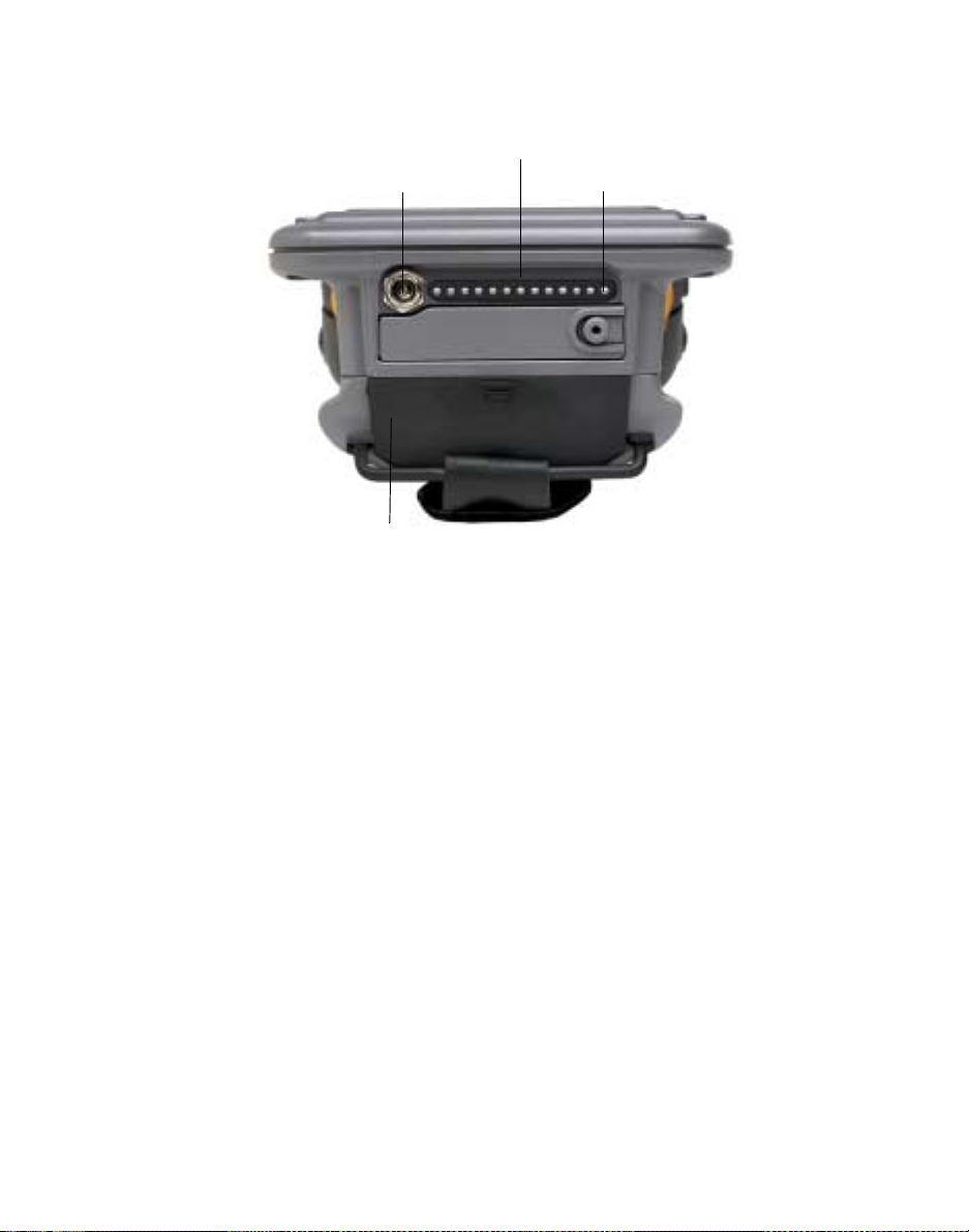
Figure 3. The PTC-2124(back view)
1. Cradle connector
3. Power jack
Pin 1
2. PCMCIA door
Disposable screen protectors
1. This connector allows the PTC to be connected quickly and easily to an SC-1124 Desktop Cradle, a VC-1124 Vehicle Cradle,
or a CP-1124 Connector Pod for communication and battery pack charging. The PCMCIA door must be closed completely
before any of these devices can be attached to the PTC. See Appendix E for this connector’s pinouts.
2. Opening this flexible door provides access to the PCMCIA slot(s). When the door is closed, it seals the PTC from dust, dirt,
and moisture. The PCMCIA slots are connectors that allow you to attach a variety of credit-card-size accessories. These
include data cards, modems, local area network (LAN) adapters, and wireless communication cards. The PTC-2124’s PCMCIA
slots accept two Type II or one Type III PCMCIA card. Type III cards must be inserted into Slot 1, the slot farthest from the
PTC’s cradle connector.
Note: If the PTC contains a factory-installed
LAN radio, only one PCMCIA slot,
which acceptsType II cards, is
available. Type III cards are not
supportedif the PTC contains only one
PCMCIA slot.
3. A 15 VDC, 2.7 A AC or vehicle adapter connects to this jack and to an electrical outlet or a vehicle’s cigarette lighter socket
or power source to recharge the PTC’s battery pack.
PTC-2124 User’sGuide 29
Page 42

Chapter 3 ConfiguringTN-3270/5250
30 PTC-2124 User’sGuide
Page 43

Drive lettering and boot sequence
Without Card and Socket services
applies only during a boot sequence.
Chapter
Drive lettering
The PTC’s operating system identifies drive letters
according to the PTC’s software configuration. The
following sections provide t he possible drive letter
assignments for your PTC.
Without Card and Socket services
The PTC can be bootedwithout Card and Socket
services from the compact flash or from a slot on the
PCMCIA controller.
Drive letter Assignment
7
A SRAM support in PCMCIA Slot 0.
B SRAM support in PCMCIA Slot 1.
C Internal c ompact flash hard disk
drive (if present) or ATA hard disk
drive card in Slot 0 o r 1 (replaces
drives A and B)
D or above RAM disk drives.
PTC-2124 User’sGuide 31
Page 44

Chapter 3 ConfiguringTN-3270/5250
If you boot an ATA card in Slot 0 as
drive C, the other PCMCIA slot is
currently not usable for other
PCMCIA devices.
With Card and Socket services and DOS
ThefollowingdrivelettersareassignedwhenthePTC
is used with Card and Socket services and DOS.
Drive letter Assignment
C Internal compact flash hard disk
drive.
D SRAM support or ATA hard disk
drive card in Slot 0 (based on configuration of Card services ATA driver).
E SRAM support or ATA hard disk
drive card in Slot 1 (based on configuration of Card services ATA driver).
F ATA hard disk drive c ard in Slot 0 (if
SRAM support is configured in the
ATA driver).
G ATA hard disk drive card in Slot 1 (if
SRAM support is configured in the
ATA driver).
With Card and Socket services and Windows
When the PTC is used with Card and Socket services
and Windows, drives are dynamically assigned as
they are installed and allocated.
Boot sequence
Drive boot sequence isthe orderin which the PTC
searches its disk drives (phy sical and logical) to locate
the config.sys and autoexec.bat files.
• The PTC searches for config.sys first, starting on
drive C and then searching Slot 0 (the slot closest
to the PTC’s cradle connector) until the file is
found.
• The PTC then searches for autoexec.bat,
starting on driveC and then searchingSlot 0 until
the file is found.
32 PTC-2124 User’sGuide
Page 45

Chapter
Operating the PTC
Holding the PTC
An optional hand strap is available. Use the PTC’shandgriptoholdtheunitsecurely
during use.
Positioning the antenna
If your PTC contains a radio but not an expansion
module, an externa l antenna will be attached to the
PTC. To achieve maximum signal strength for both
transmission and reception, bend the antenna at its
knuckle; then, make sure the antenna is
perpendicular to the ground, regardless of w hether
you are holding the PTC or it is installed in a
communication cradle.
8
Turning on the PTC
To turn on the PTC, press the On/Off button. The
CPU LED blinks rapidly while the PTC boots.
Refer to the PTC-2124 Software Guide
for a list of other possible wake
sources.
PTC-2124 User’sGuide 33
When the PTC is in standby mode, you can wake it by
gently tapping the tip of the stylus on the PTC’s
screen or by pressing the On/Off button.
When the PTC is in suspend mode, you can activate it
by pressing the On/Off button.
Page 46

Chapter 3 ConfiguringTN-3270/5250
Turning off the PTC
! Observe the cautions below
before suspending the PTC.
Refer to the section titled "Advanced
power management" on page 17 for
more information.
Press the On/Off button to suspend the PTC (or put it
to sleep). Suspending the PTC saves power and allows
the unit to resume operation exactly where it left off.
In addition, the PTC automatica lly enters standby
mode if it has not been used for approximately 1
minute.
Power-off cautions
Before you suspend the PTC, make sure that
• the PTC is not accessing the PCMCIA slot(s) or
the hard disk driv e,
• the PTC is not communicating through its
internal radio or IrDA port, and
• you hav e saved all files as a precaution.
34 PTC-2124 User’sGuide
Page 47

Entering information on the screen
Entering information on the screen
To enter data via the PTC’s screen, use your finger to
select a menu option or the PT C’sstylustowrite
letters and numbers in a field.
! Never use anything other than
your finger or the PTC’s stylus on
the screen; otherwise, you could
damage it.
See Appendix D for tips on how to
enter data that your pen operating
environment may recognize.
Your application may allow only certain portions of
the screen to be sensitive to your finger or the stylus.
Thesearethemenu“buttons” or fields in a form. The
rest of the screen does not react.
Follow this procedure to enter information with the
stylus.
1. Hold the stylus just as you would an ink pen or
pencil.
2. To make a choice from a menu, lightly tap the tip
of the stylus (or your finger) on that choice.
3. To write data in a field on a form, use the stylus
to print the letters or numbers. Use very little
pressure when writing on the screen.
Printthe letters or numbers larger than the space
between the top and bottom of the field.
PTC-2124 User’sGuide 35
Page 48

Chapter 3 ConfiguringTN-3270/5250
36 PTC-2124 User’sGuide
Page 49
Chapter
Using the PCMCIA slots
The PTC-2124 contains two user-accessible PCMCIA
slots that can accept two Type II or one Type III
PCMCIA card or device.
Note: If the PTC contains a factory-installed
LAN radio, only one PCMCIA slot,
which acceptsType II cards, is
available. Type III cards are not
supportedif the PTC contains only one
PCMCIA slot.
Preparing a PCMCIA card
Data card
9
! If an SRAM data card is sto red f or
a long period of time, the battery
may run down, and your data will
be lost. Change the battery
periodically to protect the data on
the card.
PTC-2124 User’sGuide 37
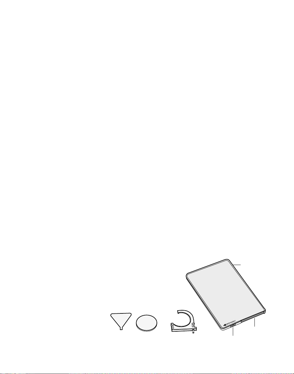
Static RAM (SRAM) data c ards may require assembly.
They use a small battery to maintain stored data.
This battery must be installed be fore the card can be
used. Refer to the instruction sheet packed with your
SRAM card for instructions on how to install the
battery.
Figure 4. Parts of a typical data card
Data card
Battery compartment
Screwdriver Lithium battery Battery holder
Write-protect switch
Page 50
Chapter 3 ConfiguringTN-3270/5250
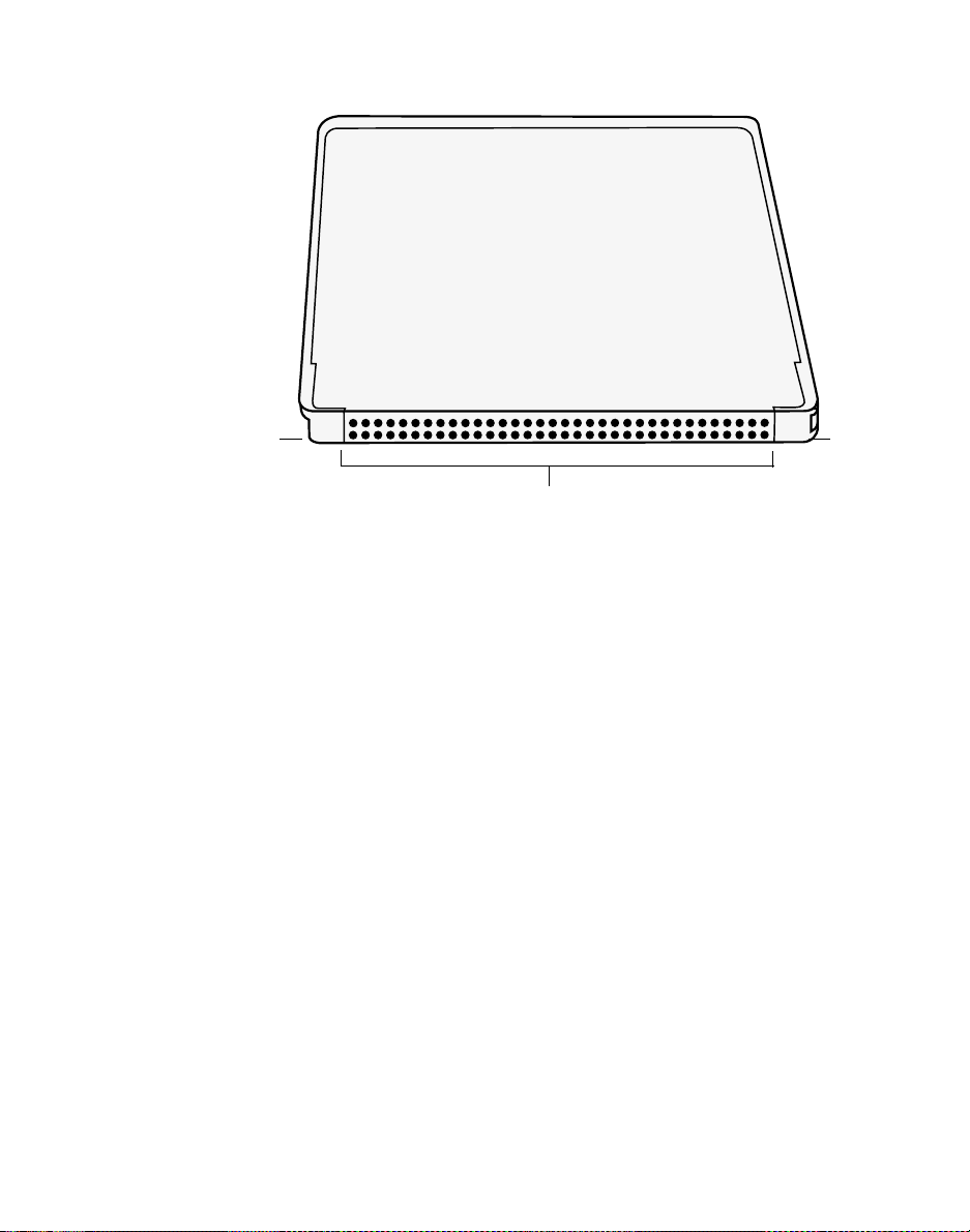
Figure5. Typical data card (connector end)
Other PCMCIA devices
Other PCMCIA devices may also need preparation
before they can be used. Refer to the instructions
packed with the device.
SlotNotch
Connector
Inserting a PCMCIA card or device
Use the following procedure to insert PCMCIA cards
or devices into the Acts PCMCIA slot(s).
! Do not force a card into the slot.
You could damage both the card
and the slot. If it does not go in
easily, turn the card over and try
again. Do not insert anything
other than PCMCIA cards or
devices into the slot. Doing so
could cause damage.
38 PTC-2124 User’sGuide
Before you b egin, examine the card. One end has two
rows of holes. This is the connector that connects the
card to the PCMCIA slot. One side of the card has a
notch, and the other has a slot. These key the card so
that it can be i nserted into t he s lot in only one way.
Onadatacard,asmallwrite-protectswitchisonthe
end opposite the connector. See Figures 4 and 5 .
1. Suspend the PTC.
2. Open the PCMCIA door by pulling the flexible
door open with your i ndex finger.
Page 51

Removing a PCMCIA card or device
3. Slot 0 (which may be occupied by a factory-
installed PCMCIA LAN radio) does not have an
eject button. Before inserting a card into Slot 0,
place a loop of tape over the card opposite its
connector so you w ill be able to remove the card
when necessary.
Type III cards must be inserted into
PCMCIA Slot 1, which is the slot
farthest from the PTC’s cradle
connector. If Slot 0 contains a
PCMCIA radio, Type III cards cannot
be inserted into slot 1.
4. Hold the card label side down and with its
connectortowardthe PTC; then, insert the card
into the slot.
5. Close the PCMCIA door.
6. Resume the PTC.
Removing a PCMCIA card or device
1. Suspend the PTC.
2. Open the PCMCIA door.
3. If the card is in Slot 0, use the tape as a pull tab to
remove the card. If the card is in slot 1, press the
Eject button located near the PCMCIA slot.
4. Close the PCMCIA door.
5. Resume the PTC.
PTC-2124 User’sGuide 39
Page 52

Chapter 3 ConfiguringTN-3270/5250
40 PTC-2124 User’sGuide
Page 53

Chapter
10
Communicating data
! Suspend the PTC before attaching
it to a communication cradle or
connector pod that has an
attached keyboard to prevent
damage to the keyboard.
Refer to the section titled "Radio" on
page 13 for information on the PTC2124’s radio options.
The PTC can communicate with a host computer via
radio, optional PCMCIA devices, its IrDA port, a
communication cradle, or a connector pod.
Communicating via radio
All radio communication is controlled by your
application program. See the instructions provided
with the program for information.
Communicating using an optional PCMCIA device
See the instructions provided with the PCMCIA
device and the inform ation in Chapter 9.
Using the IrDA port
The PTC-2124’s IrDA 1.0 port allows the PTC to
communicate via pulses of light to and from other
IrDA-compliant devices, s uch as printers an d host
systems. Follow the instructions below to use the
PTC’sIrDAport.
1. Line up the PTC and the other IrDA-compliant
device so that their IrDA ports are within 2 to 3 ft
(0.6to0.9m)ofoneanother.
2. Follow the instructions or manual provided by
your supervisor for the proper communication
procedure to follow.
PTC-2124 User’sGuide 41
Page 54

Chapter 3 ConfiguringTN-3270/5250
Connecting to a communication cradle
See the manual provided with your
cradle for instructions on how to
install the PTC.
See the documentation provided
with the connector pod for
instructions on attaching the pod to
the PTC.
The PTC-2124 can be installed in an optional SC-1124
Desktop Cradle or VC-1124 Vehicle Cradle, which
provides c ommunication, battery pack charging, and
connection to external devices.
Connecting to a connector pod
A CP-1124 Connector Pod, which provides connec tions
to an external keyboard, an Ethernet network, and
serial devices, can be attache d to the PTC-2124’s
cradle connector.
42 PTC-2124 User’sGuide
Page 55

Maintaining the battery pack
Low-battery warning
Chapter
11
See Appendix C for more information
on the Batt LED codes.
When your battery pack runs low on power, the PTC
sounds five sets of three beeps, w ith a pause between
sets, and the Batt LED glows solid red. When you
hear or see these warnings, promptly recharge the
PTC’s battery pack.
Operating the PTC with the AC or vehicle adapter connected
When the 15 VDC, 2.7 A AC or vehicle adapter is
attached to the PT C, the unit draws its power from
the electrical outlet or a vehicle’s power source, not
from the PTC’s battery pack. As a result, the PTC can
remain o n and be operated while its lithium-ion
battery pack is being fully charged.
Recharging the battery pack
The PTC’s lithium-ion battery pack can be recharged
via an AC adapter, a vehicle adapter, a
communication cradle, or a connector pod. Charge the
PTC’s battery pack befor e you use the unit for the
first t ime and whenever the PTC’sBattLEDglows
red to indicate a low-battery warning.
A lithium-ion battery pack will take
longer than 1.5 to 2.5 hours to
recharge if the charging process
occurs below room temperature.
PTC-2124 User’sGuide 43
The PTC’s built-in charger fully recharges a depleted
battery pack in 1.5 to 2. 5 hours (at room
temperature). The charger senses the power
remaining in the battery pack and decreases the
charging time accordingly.
Page 56

Chapter 3 ConfiguringTN-3270/5250
For exa mple, a half disc harged battery pack takes
0.75 to 1.25 hours to recharge.
The built-in charger also protects the battery pack
from being overcharged if charging continues after the
pack has reached a full charge.
Charging via the AC or vehicle adapter
The PTC-2124’s battery pack can be recharged in one
of two ways: via an AC adapter that c onnects to both
the PTC’s power jack and an AC electrical outlet (via
a power cord) or via a vehicle adapt er that attaches to
the PTC’s power jack and to a vehicle’scigarette
lighter socket or directly to a vehicle’s battery or fuse
panel.
The wire vehicle adapter is available
in two voltages. Make sure you use
the adapter appropriate for your
vehicle. See Appendix B for ordering
information.
If you are using the PTC outside of
the U.S. or Canada, you need a
power cord with a CEE-22 connector
at one end (for the power supply)
and an appropriate wall plug at the
other end.
Follow the instructions in this section to charge your
PTC’s battery pack via an AC adapter and an
electrical outlet or v ia v ehicle power using a cigarette
lighter vehicle adapter. To recharge the PTC’s battery
pack using a wire vehicle adapter that attaches
directly to the vehicle’s battery or fuse pane l, follow
the instructions in Appendix G.
The i tems required for recharging the battery pack
are as follows:
• A 15 VD C, 2.7 A AC adapter and an appropriate
powercordora15VDC,2.7Acigarettelighter
vehicle adapter,
• An electrical outlet providing 100 to 24 0 VAC or a
vehicle’s cigarette lighter socket.
The following procedure should be used for recharging
the battery pack:
1. Connect the appropriate power cord to the AC
adapter.
2. Connect the AC or vehicle adapter to the PTC’s
power jack; then, plug the AC adap ter’spower
cord into an electrical outlet or the vehicle adapter
into a vehicle’s cigarette lighter s ocket.
44 PTC-2124 User’sGuide
Page 57

Replacing the battery pack
The Batt LED glows to show the
recharging status. See Appendix C
for an explanation of the Batt LED
codes.
Always connect the AC adapter to
the PTC and an electrical outlet
before removing the PTC’s battery
pack if the Batt LED is blinking red to
avoid losing data in RAM.
3. Charge the battery pack for 1.5 to 2.5 hours or
until the Batt LED glows solid green.
4. When charging is finished, disconnect the AC
adapter from the electrical outlet and the PTC or
disconnect the vehicle adapter from the cigarette
lighter socket and the PTC.
Charging via a communication cradle
To charge t he PTC’s battery pack via the SC-1124 or
the VC-1124, simply in sert the PTC into the cradle,
following the instructions provided. The PTC’s battery
pack will be recharg ed autom atically.
Charging via a connector pod
To charge t he PTC’s battery pack while a CP-1124
Connector Pod is attached to the PTC, follow the
instructions provided with the pod.
Replacing the battery pack
Use the following procedures to remove and replace
the PTC’s battery pack when necessary.
Removing the battery pack
! Never leave the PTC without the
battery pack installed. The bridge
battery will drain in 4 to 5 hours,
and all data in RAM will be lost!
1. Suspend the PTC.
2. Press the PTC’stwo battery release buttons; then,
remove the battery door.
3. Tilt the PTC and allow the pack to slide out into
yourhand.
Installing a new battery pack
1. Insert the battery pack into the PT C’s battery
compartment, making sure that the battery pack’s
contacts align with the contacts inside the battery
compartment.
PTC-2124 User’sGuide 45
Page 58

Chapter 3 ConfiguringTN-3270/5250
2. Replace the battery door and push down firmly
3. Resume the PTC.
Getting the most out of the battery pack
How long the PTC operates on a fully charged battery
pack depends on
• whether you are using the hard disk drive, the
• whether your PTC is using the optional laser
• whether your PTC is spending a lot of time
• the number of times that the battery pack has
• what the surrounding temperature is.
until it locks into place.
PCMCIA slot(s), or the screen’s backlight;
scanner m odule;
communicatingthroughits radio or IrDA port;
previously been recharged;and
Maximizing operating time
You can maximize the support time of a c harged
battery pack by controlling how you use your PTC.
Here are some tips:
• Keep the battery pack at room te mperature. The
colder a battery p ack becomes, the less capacity it
has. You may see a decline in capacity below 32° F
(0° C).
• Reduce the screen’s contrastor turn the backlight
off.
• Keep radio use to a minimum.
Symbol recommends cleaning the
contacts using isopropyl alcohol or a
battery contact cleaner.
46 PTC-2124 User’sGuide
• Keep the battery pack contacts and the contacts
on the PTC clean.
Page 59

Battery pack life
Disposing of battery packs
Abnormally short operation of the
PTC after charging is usually best
corrected by replacing the battery
pack.
Refer to the section titled "Cleaning
the PTC" on page 55 for cleaning
instructions.
The PTC’s battery pack is rated for ap proximately 500
recharges,depending on the PTC’s configuration and
use.
Battery pack care
The following guidelines will help you to protect your
battery pack and get the most use out of it:
• Do not take the battery pack apart.
• Keep sharp objects away from th e battery pack
case and contacts.
• To avoid short-circuiting the battery pack, do not
touch the battery pack contacts with any metal
object.
• Do not touch the battery pack contacts. Oil from
your fingers could cause a bad connection with the
PTC.
• Periodically, clean the battery pack contacts and
the contacts on the PTC.
• Store spare battery packs in a cool, dry place out
of directsunlight.
• Do not incinerate old battery packs. See the
instructions for disposing of them in Chapter 2.
Disposing of battery packs
Lithium-ion battery p acks are hazardous waste. See
Chapter 2 for information on how to disposeof them
properly.
PTC-2124 User’sGuide 47
Page 60

Chapter 3 ConfiguringTN-3270/5250
48 PTC-2124 User’sGuide
Page 61

Chapter
12
Maintaining the bridge battery
Recharging the bridge battery
The PTC-2124 has an internal rechargeable nickelcadmium bridge battery that protects data in t he
PTC’s memory when the main battery pack runs out
of power or is being replaced. While a charged battery
pack is in the PTC, the bridge battery is inactive .
If bridge battery power is low, the
Batt LED blinks red, and the PTC
sounds five beeps.
The PTC’s ability to support RAM is
reduced if the PTC is not suspended
before the battery pack is removed.
The bridge battery is intended to provide power to the
PTC only when the battery pac k is being replaced.
Leaving a PTC without a battery pack for longer than
necessary to replace it uses up power in the bridge
battery.
Under normal operating conditions, the bridge battery
maintains its cha rge from the main battery pack.
However, w hen you receive a n ew PTC or if you leave
the main battery pack out of the PTC for an extended
period of time, you need to charge the bridge battery.
To do this, make sure the main batter y pack is
properly installed in the PTC; then, plug the AC
adapter intothe unit’spowerjackandtheACpower
cord into an electric al outlet. The bridge battery will
be charged in approximately 5 hours.
A fully charged bridge battery can safely back up the
PTC’s memory for approximately 4 to 5 hours with the
PTC suspended and main battery pack removed.
If the PTC will be stored for longer than 30 days,keep
the main battery pack installed and place the PTC
into ship/storage mode, following the instructions in
the section titled "Storing/shipping the PTC" on page
54.
PTC-2124 User’sGuide 49
Page 62

Chapter 3 ConfiguringTN-3270/5250
Conditioning the bridge battery
The PTC-2124’s nickel-cadmium bridge battery is
susceptible to “memory” effects. This means that even
if the bridge battery appears to be fu lly charged, it
may not be able t o back up the contents of the PTC’s
memory if the main battery pack is removedbefore
the PTC is placed in suspend mode.
Memoryeffects are characteristic of nickel-cadmium
battery technology. To reduce the risk of memory
effects, perform the following procedure once a month
to cond ition the bridge battery:
It is not necessary to back up data or
program files that are stored on the
internal solid-state hard disk drive.
1. Transfer any data stored in the PTC to a PCMCIA
card or a host computer. Make sure you have a
copy of any programs stored in RAM memory .
2. Remove any PCMCIA cards from the PCMCIA
slot(s).
3. Remove the main battery pack from the PTC.
4. Store the PTC and the battery pa ck somewhere
out of the way and atroom temperature. The PTC
must not be placed in a cradle or be connected to
any power sourceduring the ensuing discharge
period.
5. Allow the PTC to remain idle while the bridge
battery discharges for at least 6 hours.
6. After the 6-hour discharge period, place the ma in
battery pack back into the PTC.
7. Charge the PTC for at least 5 hours.
The bridge battery has now been conditioned and is
good for another month of service.
50 PTC-2124 User’sGuide
Page 63

Replacingthe bridge battery
Replacing the bridge battery
The PTC’s nickel-cadmium bridge bat tery is not user
replaceable. When the bridge battery no longer holds
a charge, send your PTC to an authorized Symbol
service center to have the bridge battery replaced. The
service center will insert a new bridge battery into
your PTC and follow t he proper procedure to recycle
the faile d battery.
PTC-2124 User’sGuide 51
Page 64

Chapter 3 ConfiguringTN-3270/5250
52 PTC-2124 User’sGuide
Page 65

Maintaining the PTC-2124
Operating conditions
Chapter
13
If the PTC is operated at low
temperatures, the display may
darken, and the response time may
be slow.
Although the PTC-2124 is designed to resist dust,
dirt, and moisture, it should not be used in excessively
dirty or moist conditions. The PTC can be operated at
temperatures between –4° and 122° F(–20° to 50° C).
Handling the PTC
The following info rmation will help to ensure that you
receive safe, reliable, and trouble-free service from
your PTC-2124
• Do not open the PTC’s case. Only a trained
Symbol technician can service the parts inside the
PTC.
• If you have store d the PTC or its battery pack in
below-freezingtemperatures for more than 1 hour,
the battery pack may be too cold to charge. When
the pack war ms up to room temperature, charging
will begin, provided the pack is connected to an
appropriate power s ource.
• If you store the PTC in below-freezing
temperatures for more than 1 hour, y ou can
improve the display’s performance by waiting
until the unit warms up to room temperature
before using it.
• Suspend the PTC before you replace the battery
pack.
PTC-2124 User’sGuide 53
Page 66

Chapter 3 ConfiguringTN-3270/5250
Storing/shipping the PTC
The following precautions should be taken if you plan
to store a PTC for any extended period of time
• Do not store the PTC in temperatures below –22°
• Do not store the PTC in a damp or humid
Follow the instructions below if you plan to ship the
PTCorstoreitformorethan30days.
1. Transfer any data stored in the PTC to a PCMCIA
2. Make sure you have a copy of any programs stored
3. Remove any PCMCIA cards from the PCMCIA
4. Remove the PTC’s battery pack, followi ng the
F(–30° C) or above 158° F(70° C).
environment.
card or a host c omputer.
in the PTC.
slot(s).
instructions in Chapter 11.
Pressing the Reset button places the
PTC in ship mode, which results in
maximum shelf storage time. See
“Resetting the PTC” in Chapter 15
for more information.
54 PTC-2124 User’sGuide
5. Use a thin, nonconductive object (such as a coffee
stirrer) to press the Reset button inside the
battery co mpartment.
6. Reinstall the PTC’s battery pack, following the
instructions in Chapter 11.
7. Recharge the PTC’s battery pack.
8. Pack the PTC in the original packing mate rial or
in a padded box and put it in a safe place, away
from dust, dirt, humidity, and excessive cold or
heat.
9. Recharge the PTC’s battery pack every 60 days.
Page 67

Cleaning the PTC
Cleaning the PTC
The follo wing items are needed for cleaning a PTC
• A soft, lint-free cloth,
• A nonabrasive liquid cleaner, such as Windex,
• Isopropyl alcohol or a ba ttery contact cleaner.
! Do not soak the cloth and do not
spray or pour cleaning liquids
directly onto the PTC.
To clean the PTC, slightly moisten a soft, clean, lintfree cloth with a mild, nonabrasive liquid cleaner and
wipetheoutsidesurfaces.Donotuseapapertowel.
To clean the batterypack contacts and the contacts on
the P TC, use a cloth moistened with isopropyl alcohol
or a battery contact cleaner.
If the PTC beco mes ex tremely dirty or if liquids, dirt,
or other foreign materials get inside the case, contact
your Symbol service representative.
Servicing the PTC
Do not attempt to service the PTC. Only a trained
Symbol technician may service the PTC. Follow the
procedure set up by your organization to have th e
PTC serviced properly.
Disposing of the PTC
When your PTC has reached the end of its useful life,
do not throw it away. Send it to an authorized Symbol
service center for bridge battery removal and
recycling before the unit is disposed of permanently.
.
PTC-2124 User’sGuide 55
Page 68

Chapter 3 ConfiguringTN-3270/5250
56 PTC-2124 User’sGuide
Page 69

Chapter
14
Troubleshooting
As a first step in resolving problems, consider the
points in this section.
General
• As soon as an error occurs, stop w hat you a re
doing. Write down what the system is doing and
what actions you took immediately before the
problem occurred.
• If any messages display on the s creen, look them
up in your software manuals.
• Do any lights glow? Which ones? Do they stay on
or blink?
• Hasthe speakersounded? How manytimesand in
what pa ttern? Do the beeps seem related to
anything you are doing?
• Is the PTC making any unusual noises?
• Confirm that the PTC has been set up properly.
• Can you run some applications but not others?
Check that your software is properlyinstalledand
that the application program and data files are
not corrupted.
See Chapter 15 for instructions. • If the PTC locks up (the application stops
responding), perform a warm r eboot.
PTC-2124 User’sGuide 57
Page 70

Chapter 3 ConfiguringTN-3270/5250
Beep codes
The PTC beeps to warn you when either the battery
pack or the bridge battery is running low on power.
Five sets of three beeps
Five s ets of three beeps, with a pause between sets,
meansthat the battery pack is running low. When
you hear these beeps, promptly recharge the PTC’s
battery pack.
Five beeps
Five beeps means that the bridge battery is running
out of power. If you hear these beeps, immediately
recharge the bridge battery.
LED codes
See Appendix C for an explanation of the CPU and
Batt LED codes.
Common solutions
If you experience any of the problems in this section,
follow the instructions provided.
PTC does not turn on
• Charge o r replace the battery pack.
See Chapter 15 for instructions. • Try to reboot the PTC.
• If the PTC still does no t operate, follo w your
organization’s procedureto have the PTC serviced.
58 PTC-2124 User’sGuide
Page 71

Common solutions
PTC does not respond correctly to the stylus
• The PTC’s resistivetouch panel digitizermay
need to be recalibrated. Make arrangements with
your VAR representative or an authorized Symbol
servicecentertohavetheunit’s digitizer
recalibrated.
• If the PTC s till does not respond correctly, follow
your organization’s procedure to have the PTC
serviced.
PTC does not recognize the information written on the screen
• Wait until the PTC warms up to room
temperature if it has been stored or used in the
cold.
• Refer to Appendix D for tips on how to form
letters and numbers correctly for system
recognition.
PTC’s screen is slow to refresh
• Wait until the PTC warms up to room
temperature if it has been stored or used in the
cold.
Radio fails to establish contact
• Change your location by a few feet and transmit
again.
• Recharge or replace the PTC’s battery pack.
• Make sure the receiving equipment is turned on
and is properly connected to the host computer.
• If the PTC still does no t establish contact, follow
your organization’s procedure to have the PTC
serviced.
PTC-2124 User’sGuide 59
Page 72

Chapter 3 ConfiguringTN-3270/5250
Battery pack does not hold a full charge after recharging
• Thebatterypackmaybefaultyorwornout,
Laser scanner module does not read a label
• Makesurethelabelyouaretryingtoscanisone
• Move the scanner lens closer to or farther away
• Change the angle of the laser scanner to the bar-
• Clean the scannerlens.
• The PTC’s application program may not support
particularly if it is old. Replace it with a new on e.
of the bar-code types that your PTC is
programmed t o recognize.
from the bar-code label. You may not be scanning
at the correct distance.
code label. You may be too far above or below the
label or too far to the side to scan properly.
scanned data at this particular field. Consult the
documentation for the PTC’s application program
to determine when the scanner and scan triggers
are enabled.
• Point the scanner at a blank surface and press one
of the scan triggers. Look for the scanning line
that appears on the blank surface when the
scanner i s operating. If no scanning l ine appears,
follow your organization’s procedure to have the
laser s canner module serviced.
• If the bar code is oriented along t he circumference
of a round tube, the scanner will not be able to
read it.
Application locks up
• Reboot the PTC using the instructions in
Chapter 15.
• Reset the PTC using the instructions in
Chapter 15.
• Follow your organization’s procedure to have the
PTC serviced.
60 PTC-2124 User’sGuide
Page 73

Getting help
Getting help
Try the followingbefore contacting Symbol:
• Review the troubleshooting sections in your pen
operating environment and Microsoft manuals.
• Review the documentation for your application.
Cannot correct the problem
Contact your Symbol service
representative for information on
purchasing a service contract.
• Notify your Symbol service representative, or
• Contact the Symbol Cu stomer SupportCenter
at 1-800-653-5350.
PTC-2124 User’sGuide 61
Page 74

Chapter 3 ConfiguringTN-3270/5250
62 PTC-2124 User’sGuide
Page 75

Chapter
15
Rebooting/Resetting the PTC
Under normal circumstances, a
reboot will unlock the unit.
! Do not reboot the PTC unless
absolutely necessary. Rebooting
the PTC erases all programs and
data in RAM.
The screen is blank for 15 seconds,
and the CPU LED blinks red quickly
while the unit boots up.
If your application locks up (stops responding), reboot
the PTC using one of the following procedures. If the
reboot is unsuccessful, follow the instructions on the
next page to reset the PTC.
Rebooting the PTC
Rebooting stops the PTC, resets the unit, and then
restarts (boots) it. When the PTC starts again, it
returns to the operating system.
Via a warm boot
1. Suspend the PTC.
2. Hold down the Contrast button an d the On/Off
button.
3. Release the Contrast button.
4. Press and release the Contrast button.
5. Release the On/Off button. The warm boot is now
complete.
6. Press the On/Off button to restart the PTC.
From an attached keyboard
If a keyboard is attached to your PTC-2124 via a
communication cradle or connector pod, you can
reboot the unit by pressing the Ctrl, Alt,andDelete
keys simultaneously.
PTC-2124 User’sGuide 63
Page 76

Chapter 3 ConfiguringTN-3270/5250
Via the pop-up keyboard from the DOS prompt
To reboot the PTC from the pop-up keyboard, go to the
DOS prompt and tap the tip of the stylus on the PTC’s
screen three times. When the pop-up keyboard
displays, use the stylus to select the Ctrl, Alt,and
Del keys (in this order).
Resetting the PTC
! Never reset the PTC unless
absolutely necessary. Resetting
the PTC erases all programs and
data in RAM.
The PTC does not have to be on to
be reset.
If rebooting is not effective, you may have to reset the
PTC. When the PTC reboots after a reset, it returns to
the operating system.
To reset a PTC, a thin, nonconductive object (for
example, a plastic coffee stirrer) is required.
The following procedure should be preformed:
1. Remove the PTC’s battery pack, followi ng the
instructions in Chapter 11.
2. Use a thin, nonconductive object to press the
Reset button within the battery comp artment.
3. Reinstall the PTC’s battery pack, following the
instructions in Chapter 11.
4. Press the On/Off button.
The CPU LED blinks red quickly and the screen is
blank for approximately 10 seconds while the PTC
reboots.
64 PTC-2124 User’sGuide
Page 77

Specifications
Appendix A
Specifications
Communication and I/O
Radio: Choice of any single radio:
LAN options:
Direct-sequence spread
spectrum, 2.4 GHz directsequence 802.11-compliant
spread spectrum, or 2.4 GHz
frequency-hopping 802.11compliant spread spectrum
WAN options:
DataTAC or Mobitex
Cradleconnector: 13-pin connector; connects to
SC-1124 connector: Desktop
Cradle, VC-1124 Vehicle
Cradle, or CP-1124 Connector
Pod
If your PTC contains a factoryinstalled LAN radio, only one PCMCIA
slot, which accepts Type II cards, is
available.
PCMCIA slots: Accept two Type II or one Type
III PCMCIA device
IrDA 1.0 port: Infrared lens for serial IrDA
communications; up to 115.2
Kbps
Display
Type: Transflective monochrome
LCD
Size: 4.7 in./11.7 cm (diagonal)
Resolution: 1/4 VGA, 320 x 240 pixels
Digitizer: ‘ Transparent resistive to uch
panel
PTC-2124 User’sGuide 65
Page 78

Chapter 3 ConfiguringTN-3270/5250
Electrical
Battery pack: Lithium-io n
Bridge batte ry: 120 mAh nickel-cadmium
AC adapter: Input: 100-240 VAC
Output: 15 VDC @ 2.7 A
Vehicle adapt er: Input: 9–16 or 11–28 VDC
Output: 15 VDC @ 2.7 A
Environmental
@ 50/60 Hz
If the PTC is operated at low
temperatures, the display may
darken, and the response time may
slow.
Operating
temperature: –4° to 1 22° F(–20° to 50° C)
Battery charging will take
longer i f performed below room
temperature.
Storage temperature : –22° to 158° F(–30° to 70° C)
Operating humidity: 0 to 95% noncondensing
@ 104° F(40° C)
Vibration: 30 Hz orbital movemen t with
0.06 displacement
Shock: 3 ft (1 m) drop to concrete
surface
Operating altitude: Up to 15,000 ft (4,572 m)
Rain: Raindriponallsurfaces
ESD protec tio n: 15 kv; no damage (U.S. and
Canada) 8 k v; no reset
(Europe)
Expansion modules (optional)
Laser scanner: Standard range
66 PTC-2124 User’sGuide
Page 79

Memory
ROM: 512 KB flash PROM
RAM: 4, 20, 36, or 64 MB
Microprocessor
Specifications
The PTC can also be set to operate at
33 or 66 MHz to reduce power
consumption. Refer to the section
titled "Processor" on p. 9 for
instructions.
If your PTC contains a factoryinstalled LAN radio, only one PCMCIA
slot, which accepts Type II cards, is
available.
Type and speed: AMD Elan SC400 (100 MHz)
Operating system/environment
Operating system: MS-DOS 6.22 or Windows CE 2.12
Pen operating
environment: PenRight!
Physical
Length: 7.6 in./19.3 cm
Width: 4.5 in./11. 4 cm
Thickness: 2.4 in./6.1 cm
Weight: 24.5 oz/0.7 kg (with battery
pack)
Storage
PCMCIA: Two Type II or one Type III
PCMCIA data card
Hard drive: Internal solid-state compact
flash hard disk drive; 8 MB
nominal
Stylus
Type: Aluminum with spring-loaded
Teflon tip
PTC-2124 User’sGuide 67
Page 80

Chapter 3 ConfiguringTN-3270/5250
68 PTC-2124 User’sGuide
Page 81

Accessory part numbers
Accessorypart numbers
Appendix B
Contact your Symbol sales
representative to order any of the
following parts.
The following table contains part numbers for
ordering PTC-21 24 accessories.
Table 1. Accessory part numbers SC-1124 Desktop Cradle
Item Part Number
Hardware
Lithium-ion battery pack 21588-000
AC adapter (15 VDC, 2.7 A) 20991-000
U.S. power cord 09038-000
Stylus 19415-000
Vehicle adapters (15 VDC, 2.7 A)
9 to 1 6 volt cigar ette lighter adapter 21438-001
9 to 16 volt wire adapter 21438-002
11 to 28 volt wire adapter 23662-001
Accessories
CP-1124 conne ctor pod 23 450-001
SC-1124 desk to p cradle 23449-001
VC-1124 vehicle Cradle 23448-001
Disposable screen protectors 30783-001
PTC-2124 User’sGuide 69
Page 82

Chapter 3 ConfiguringTN-3270/5250
Item Part Number
Software
Symbol Pen-Based SC400 Software
Development Kit
Related publications
SC-1124/VC-1124 User’s Guide 24390-000
CP-1124 Read-Me-First Sheet 23382-002
PTC-2124 Software Guide 24136-200
24136-000
70 PTC-2124 User’sGuide
Page 83

CPU LED codes
Appendix C
This appendix interprets the codes for both of the
PTC’s light-emittingdiodes(LEDs).
CPU LED codes
The PTC’s CPU LED glows or blinks to indicate the
status of the PTC.
Table 2. CPU LED codes
Color Explanation
Blinking red
(every 1/4 second)
Blinking red
(every 2 seconds)
Blinking red
(every 4 seconds)
Solid red The P TC’sscannerisactive.
Solid gre en The PTC has successfully
PTC is booting.
PTC is in softwarestandby
mode.
PTC is in suspend mode.
scanned a bar code.
PTC-2124 User’sGuide 71
Page 84

Chapter 3 ConfiguringTN-3270/5250
Batt LED codes
The PTC’s Batt LED glows or blinks to indicate the
status of battery pack charging.
Table 3. Batt LED codes
Color Explanation
Solid red Low battery pack—recharge it.
Blinking red Low b rid ge battery—recharge
bridge battery or send PTC to
Symbol service center to have
bridge ba ttery replaced.
Blinking green Battery pack is being charged.
Solid green Battery pack has reached a full
charge.
Alternating red/
green
72 PTC-2124 User’sGuide
Reset the PTC. If problem
persists frequently, consult the
PSC. The charging system may
have detected a component
failure.
Page 85
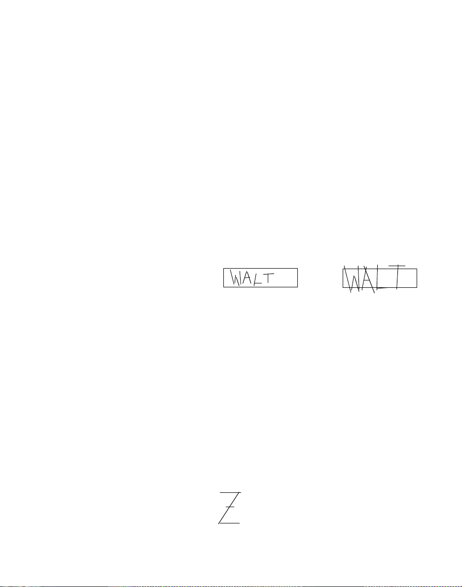
Tips on using a stylus to enter data
Appendix D
Tips on using a stylus to enter data
This appendix provides helpful tips on how to use a
stylus to write on the PTC’s screen.
General guidelines
Follow the guidelines listed below to use the stylus to
enter data on the PTC’s screen.
• Write larger than the field. Writing too small is
the primary cause of poor recognition.
Wrong Better
Name:
• Print neatly, making sure to form characters
distinctly.
• Leave room between characters, but make sure
that all strokes of a single character are
connected.
• Print uppercase letters larger than lowercase
letters.
• Write commas near the bottom of the field, and
apostrophes near the top of the field.·
• When printing colons or semicolons, draw the top
dot first.
• Write the letter “Z” with a small horizontal line
through its middle.
PTC-2124 User’sGuide 73
Name:
Page 86

Chapter 3 ConfiguringTN-3270/5250
• Write the number “0” with a slash through it.
• Write the number “1” with a small horizontal line
• Write the number “5” with two strokes rather
under it.
than one.
74 PTC-2124 User’sGuide
Page 87

Connector pinouts
Connector pinouts
Appendix E
The cradle connector is shown in
Figure 3 on page 29, with the
position of Pin 1 indicated.
Pin Signal name Description Signal level
1GND Ground.
2OTXS#or
COMA_ RTS#
3ORXS#or
COMA_CTS#
4 VCHARGE Charger voltage +15 VDC @ 2.7 A. +15 VDC
5OTXDor
COMA_TXD#
6ORXDor
COMA_RXD#
7 RX D+ Ethernet receive pair. +5 V
This appendix provides pinouts of the PTC-2124’s
cradle co nnector and scanner expansion mo du le
connector. It also lists pinouts for the CP-1124
Connector Pod’s keyboard port, Ethernet port, and
serial p ort.
Table 4. PTC-2124 cradle connector pinouts
COM2—opticaltransmit statusor
4-wirerequest to send.
COM2—optical receive status or
4-wireclear to s end
COM2—optical transmit data or
4-wire transmit d a ta.
COM2—optical receive data or
4-wire receive data.
RS-232
RS-232
RS-232
RS-232
8RXD9 TXD+ Ethernet transmit pair. +5 V
10 TXD 11 VCC VCC Power (+5 VDC @ 100 mA) +5 VDC
12 KC LK Keyboard clock. +5 V
13 KDAT Ke yboard data. +5 V
PTC-2124 User’sGuide 75
Page 88

Chapter 3 ConfiguringTN-3270/5250
With the top cover of the scanner
expansion module removed, the
scanner expansion module connector
is located just under the top of the
PTC housing. Refer to Figure 2. The
PTC-2124 (right side view) on page
28. The scanner expansion module
connector is the small, white, 30-pin
connector, with Pin 1 located on the
right when viewing the PTC from the
top.
Table 5 . PTC-2124 scanner expansion module connector
pinouts
Pin Signal Description
1 CONFIG0 Configuration 0
2VSCAN_5V Scanner+5voltpower
3 GND Ground
4 MARKER/
SCAN_RXD#
5 SCAN_DTR# Scanner data terminal
6 T RIG_IM G Connected to 47.5 KΩ
7 PEN_EN# Pen enable
8 SCAN_TXD# Scanner transmit data
9 BARCODE/
SCAN_DSR
Marker or scanner receive
data
ready
resistor to ground
Wand in/scanner data set
ready
10 LED_EN LED enable
11 TRIG# Trigger
12 MARKER/
SCAN_RXD#
13 SCAN_TXD# Scanner transmit data
14 SCAN_SOS Scanner start of scan
15 SCAN_CTS# Scanner clear to send
16 SCAN_RTS# Scanner request to send
17 SCAN _CD# Scanner carrier detect
18 VSCAN _PWR Scanner + 7.2 volt power
19 VSCAN _PWR Scanner + 7.2 volt power
76 PTC-2124 User’sGuide
Marker/scanner receive
data
Page 89

Connector pinouts
Pin Signal Description
20 VSCAN _PWR Scanner + 7.2 volt power
21 SCAN _ID 0 Scanner ID bit 0
22 SCAN _ID 1 Scanner ID bit 1
23 SCAN _ID 2 Scanner ID bit 2
24 SCAN _ID 3 Scanner ID bit 3
25 GND Ground
26 GND Ground
27 GND Ground
28 CONFIG2 Configuration 2
29 VSCAN_5V Scanner +5-volt power
30 CH_GND Chassis ground
Table 6. CP-1124 keyboard port pinouts
Pin Signal Description
1 KDAT Keyboarddata (TTL sig-
nals)
2 N/C No connection
3GNDGNDground
4 VCC Keyboard power (+5 VDC)
5 KCLK Keyboardclock (TTL signal)
6 N/C No connection
PTC-2124 User’sGuide 77
Page 90

Chapter 3 ConfiguringTN-3270/5250
Table 7. CP-1124 Ethernet port pinouts
Table 8 . CP-1124 serial port pinouts
Pin Signal Description
1 TXD+ Ethernet transmit pair
2TXD3 RXD+ Ethernet receive pair
4RXD5 N/C No connection
6 N/C No connection
7 N/C No connection
8 N/C No connection
Pin Signal Description
1 N/C No connection
2RXDReceivedata
3TXDTransmitdata
4 N/C No connection
5GNDSignalground
6 N/C No connection
7 RTS Request to send
8 CTS Clearto send
9 N/C No connection
78 PTC-2124 User’sGuide
Page 91

Using the optional expansion modules
Appendix F
Using the optional expansion modules
Follow the instructions in this appendix to use the
PTC-2124’s optionallaser scanner module.
Using the laser scanner module
If your PTC-2124 has an attached laser scanner
module, the unit can be pr ogrammed to recognize,
read, and discriminate automatically am ong six 1D
bar-code types. See the n ext page for a list of these
bar-code typ es and the information provided by your
organization for details on h ow your PTC h as been
programmed.
$Do not stare into the PTC’s
laser beam or point the
scanner at anyone’s eyes.
Permanent eye damage could
result.
See the information provided by
your organization for the
recommended scanning distance.
Your application program may not
support scanned data for all fields.
Consult the documentation for your
application to determine when the
scanner and scan triggers are
enabled.
PTC-2124 User’sGuide 79
Follow t his procedure to scan bar-code labels with a
laser s canner module.
1. Point the PT C at the label to be scanned.
Themaximumdistancefromthescannerlensto
the label depends on the size of the label b eing
scanned and the type of laser that was selected by
your organization.
2. Press one of the PTC’s scan triggers to start
scanning.
3. Watch the line of light made by the scanner as it
scans the bar code.
4. If the scan is successful, the CPU L ED glows solid
green and the PTC beeps.
5. Hold th e PTC at an angle to the bar code so that
the sc anning line is perpendicular to the bars in
the bar-code label. Make sure the line passes over
all of the bars.
Page 92

Chapter 3 ConfiguringTN-3270/5250
Supported bar codes
Other bar-code types (such as Code
11 and Code 93) are available by
special order. However, the PTC can
support only six bar-code types, so
any additional bar code will have to
replace one of the default bar codes.
The PTC-2124’s optional laser scanner module can be
programmed t o read and automatically discriminate
among the following 1D bar-code types:
• Codabar
• Code 2 o f 5
• Code 39
• Code 128
• Plessey
• UPC/EAN
80 PTC-2124 User’sGuide
Page 93

Connecting a wire vehicle adapter to the PTC
Appendix G
Connecting a wire vehicle adapter to the
PTC
$The procedures in this
appendix should be performed
only by qualified maintenance
personnel.
The wire vehicle adapter is available
in two voltages. Make sure you use
the adapter appropriate for your
vehicle. See Appendix B for ordering
information.
This appendix provides instructions for connecting a
wire vehicle adapter to the PTC-2124 ’spowerjackand
to a vehicle’sconstant12or24VDCpowersource,
such as the batte ry or fuse panel. When the PTC is
connected directly to the vehicle’s power source, power
is supplied to operate the PTC and to recharge its
battery pack.
Electrical installation
Electrical installation varies according to vehicle. U se
the fo llowing inf ormation to plan your installation.
The wire vehicle adapter consists of two wires
attached to a power connector. The c onnector attaches
to the PTC’s power jack, and the wires are used for
vehicle hookup. The wires are defined in Table 9.
Table 9. PTC-2124 wire vehicle adapter
Wire Description
Power (+) Smaller wire with writing; termi-
natedin a spade lug.
Ground (– Ground (–) larger wir e without
writing; terminated in a ring lug for
a#8stud.
PTC-2124 User’sGuide 81
Page 94

Chapter 3 ConfiguringTN-3270/5250
Installing the power wire
Follow the appropriate set of
instructions on the following pages.
Connect the power wire to a continuous 12 or 24 VDC
source (one that providespowereven when the vehicle
is not running). This can be a direct connection to the
vehicle’s battery or a connection to a continuous
source on the vehicle’sfusepanel.
Connecting to a battery with top terminals
The following items are required for connecting the
power wire directly to a battery:
• Alengthofwire
• Two crimped splices
• A power drill and an assortment of drill bits
• A snap-in bushing
• A wire stripping/crimping tool
• Afuselink
• A 3/8 in. terminal ring
• A 3/8 in. by1 1/2 in. bolt
• Two 3/8 in. washers
• A3/8in.nut
• Socket wrenches or box wrenches
Refer to Figure 7 as y ou perform the following steps:
If the wire is not long enough, you
will need an additional length of
wire.
82 PTC-2124 User’sGuide
1. Determine if the power wire is long enough to
reach the battery’s positive (+) terminal.
2. If necessary, use a crimped wire splice (for #18
AWG) to join the additional length o f wire to the
power wire after cutting off the s pade lug.
3. If nece ssary, drill a hole through the vehicle’s
firewall for the power wire.
Page 95

3/8 in. washers
3/8 in. nut
Connecting a wire vehicle adapter to the PTC
Figure 6. Connecting to a top-terminal battery
3/8 in. by 1 1/2 in. bolt
Crimped splice
Crimped terminal ring
3/8 in. crimped terminal ring
4. If you have drilled a hole through the firewall
orother sheet metal, insert a snap-in bushing to
protect the wire.
5. Run the wire from inside the cab to the batter y.
6. Strip 1/4 in . (0.64 cm ) of insulation from t he end of
Fuse link
the power wire or the extension wire.
7. Attachafuselinktothestrippedendofthewire
using a crimped splice. If necessary, crimp a 3/8
in. terminal r ing onto the free end of the fuse link.
Positive cable
Fuse Link
Crimped splice
Power wire (+)
8. Remove the bolt from the battery’s positive (+)
terminal.
9. Replace the bolt with a 3/8 x 1 1/2 in. bolt.
PTC-2124 User’sGuide 83
Page 96

Chapter 3 ConfiguringTN-3270/5250
10. Slide a 3/8 in. washer onto the bolt.
11. Slide the terminal ring on the power wire’sfuse
12. Slide a s econd 3/8 in. washer onto the bolt.
13. Thread a 3/8 in. nut onto the bolt.
14. Tighten the nut securely.
Connecting to a battery with side terminals
The following items are required for connecting the
power wire directly to a battery:
• Alengthofwire
• Two crimped splices
• A power drill and an assortment of drill bits
• A snap-in bushing
• A wire stripping/crimping tool
link o nto the bolt.
• Afuselink
• A 3/8 in. terminal ring
• A 3/8 x 1 1/2 in. bolt
• A3/8in.nut
• Two 3/8 in. washers
• Socket wrenches or box wrenches
Refer to Figure 8 as y ou perform the following steps:
If the wire is not long enough, you
will need an additional length of
wire.
84 PTC-2124 User’sGuide
1. Determine whether the power wire is long enough
to reach the battery’s positive (+) terminal.
2. If necessary, use a crimped wire splice (for #18
AWG) to join the additional length o f wire to the
power wire after cutting off the s pade lug.
Page 97
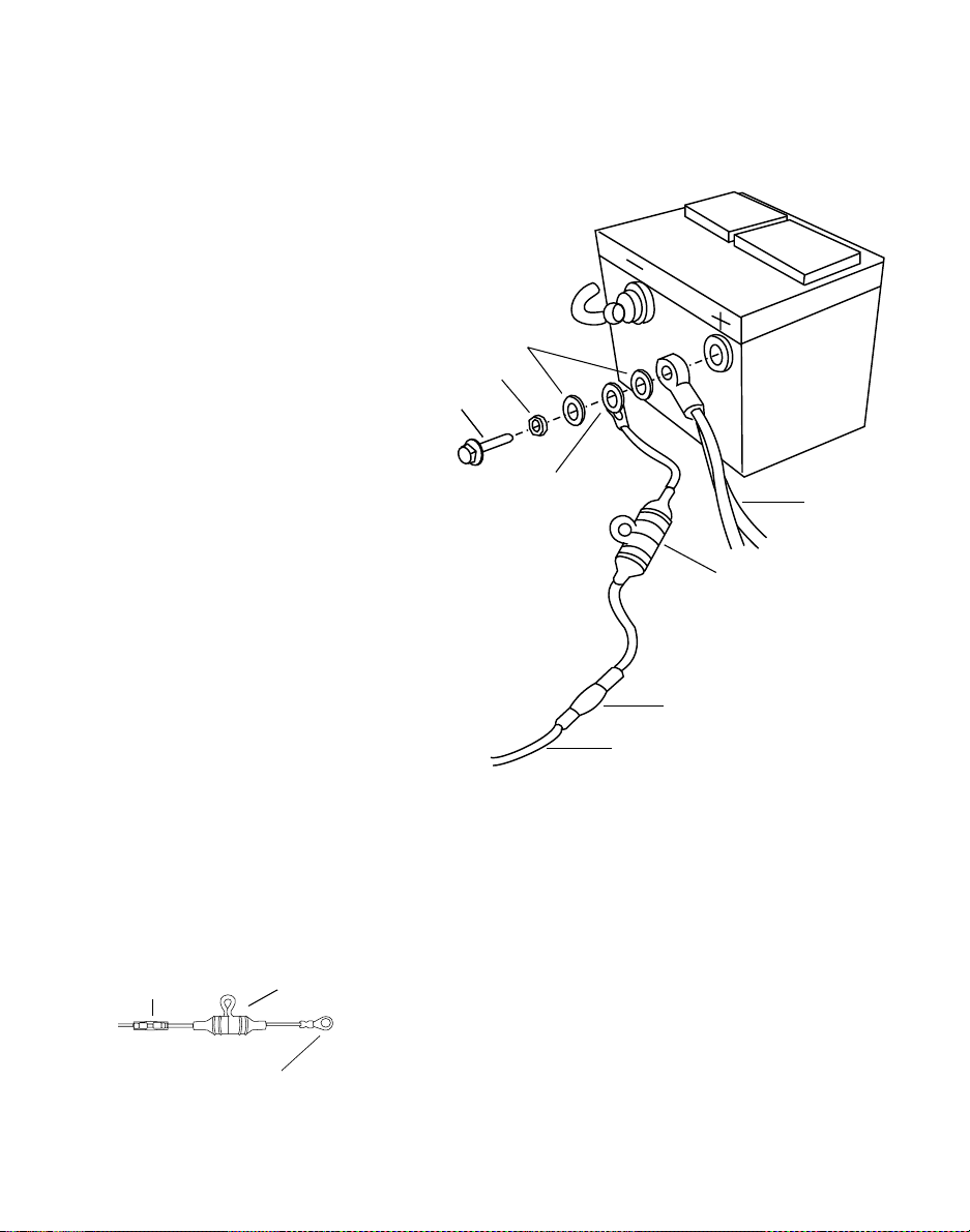
Connecting a wire vehicle adapter to the PTC
3. If nece ssary, drill a hole through the vehicle’s
firewall for the power wire.
Figure 7. Connecting to a side-terminal battery
3/8 in. washers
3/8 in. nut
3/8 in. by 1 1/2 in. bolt
Crimped splice
Crimped terminal ring
Fuse link
3/8 in. crimped terminal ring
Positive cable
Fuse link
Crimped splice
Power wire
4. If you have drilled a hole through the firewall or
other sheet me tal, insert a snap-in bushing to
protect the wire.
5. Run the wire from inside the cab to the batter y.
6. Strip 1/4 in . (0.64 cm ) of insulation from t he end of
the power wire or the extension wire.
7. Attachafuselinktothestrippedendofthewire
using a crimped splice. If necessary, crimp a 3/8
in. terminal r ing onto the free end of the fuse link.
PTC-2124 User’sGuide 85
Page 98

Chapter 3 ConfiguringTN-3270/5250
8. Remove the bolt from the battery’s positive (+)
9. Thread a 3/8 in. nut onto a 3/8 x 1 1/2 in. bolt.
10. Slide one 3/8 in. washer onto the bolt.
11. Slide the terminal ring on the power wire’sfuse
12. Slide a s econd 3/8 in. washer onto the bolt.
13. Slide the vehicle’s positive (+) cable c onnector onto
14. Screw the bolt into the battery’s positive terminal
15. If necessary, tighten the nut installed on the bolt
Connecting to the fuse panel
terminal.
link o nto the bolt.
the bolt.
and tighten it securely.
to secure the washers and cable connectors in
place.
The following items are required for connecting the
power wire to a fuse pa nel:
• A wire stripping/crimping tool
• An assortment of crimp connectors
• A truck or automotive fuse
The following steps should then be performed:
1. Strip 1/4 in . (0.64 cm ) of insulation from t he end of
the power wire.
2. Crimp the correct connector for your fuse pa nel
onto the power wire.
Many fuse panels require a female
spade connector.
86 PTC-2124 User’sGuide
3. Connect the power wire to the fuse panel.
4. Install a fuse of the proper rating (7.5 A) in the
fuse panel.
Page 99

Connecting a wire vehicle adapter to the PTC
Installing the ground wire
The following items are required for the installation of
agroundwire:
• A wire stripping/crimping tool
• An assortment of crimped terminal rings
• A power drill
• An ass ortment of drill bits
• Ametalpunch
• An assortment of sheet-metal screws
• An assortment of washers
• A screwdriver
The ground wire should be installed by performing
the following steps. The following items are required
for connecting the power wire to a fuse panel:
1. Select a place on the vehicle cab’s s heet metal
where you will attach the ground wire.
2. Drill a small hole at that spot.
3. With a punch, dimple and enlarge the hole
slightly.
4. Scrape off a small circle of paint around the hole.
You must expose the metal for a g ood electrical
contact.
5. Use a sheet-metal screw and washer of the
appropriatesizetosecurethegroundwire’s
terminal ring to the sheet metal.
Securing the wires
Wire ties should be used to secure the installed wires.
Secure the wires in place every 12 to 18 inches (30 to
46 centimeters) using wire ties.
PTC-2124 User’sGuide 87
Page 100

Chapter 3 ConfiguringTN-3270/5250
• Make sure that the wires do not interfere with
• Make sure the wires will not be damaged by any
Connecting the wire vehicle adapter to the PTC
1. Place the PTC inside the vehicle’s cab, provided
2. Attach the vehicle adap ter’s power connector to
3. Securely mount the vehicle adapter inside the
4. Power is automatically applied to the PTC, and
5. If you wish to remove the PTC from the vehicle,
any equipment or vehicle controls.
engine parts or sheet metal.
electrical installation is complete.
the PTC’spowerjack.
vehicle’s cab u sing double-sided tape.
recharging of the PTC’s battery pack be gins.
Charge the battery pack for 1.5 to 2.5 hours or
until the Batt LED glows solid green.
disconnect the vehicle adapter from the PTC’s
power jack. If the PTC remains connected to
vehicle power, the PTC willcontinue to receive
power from the vehicle’s batt ery or fuse panel, not
from its battery p a ck.
88 PTC-2124 User’sGuide
 Loading...