

Page 1

PDT 6100 Series
Product Reference Guide
Page 2

PDT 6100 Series
Product Reference Guide
70-33222-02
Revision A
June 2001
Page 3

2001 by Symbol Technologies, Inc. All rights reserved.
No part of this publication may be reproduced or used in any form, or by any electrical or
mechanical means, without permission in writing from Symbol. This includes electronic or
mechanical means, such as photocopying, recording, or information storage and retrieval
systems. The material in this manual is subject to change without notice.
The software is provided strictly on an “as is” basis. All software, including firmware,
furnished to the user is on a licensed basis. Symbol grants to the user a non-transferable and
non-exclusive license to use each software or firmware program delivered hereunder (licensed
program). Except as noted below, such license may not be assigned, sublicensed, or otherwise
transferred by the user without prior written consent of Symbol. No right to copy a licensed
program in whole or in part is granted, except as permitted under copyright law. The user
shall not modify, merge, or incorporate any form or portion of a licensed program with other
program material, create a derivative work from a licensed program, or use a licensed
program in a network without written permission from Symbol. The user agrees to maintain
Symbol’s copyright notice on the licensed programs delivered hereunder, and to include the
same on any authorized copies it makes, in whole or in part. The user agrees not to
decompile, disassemble, decode, or reverse engineer any licensed program delivered to the
user or any portion thereof.
Symbol reserves the right to make changes to any software or product to improve reliability,
function, or design.
Symbol does not assume any product liability arising out of, or in connection with, the
application or use of any product, circuit, or application described herein.
No license is granted, either expressly or by implication, estoppel, or otherwise under any
Symbol Technologies, Inc., intellectual property rights. An implied license only exists for
equipment, circuits, and subsystems contained in Symbol products.
Symbol, Spectrum One, and Spectrum24 are registered trademarks of Symbol Technologies,
Inc. Other product names mentioned in this manual may be trademarks or registered
trademarks of their respective companies and are hereby acknowledged.
Symbol Technologies, Inc.
One Symbol Plaza
Holtsville, New York 11742-1300
http://www.symbol.com
ii
Page 4

Contents
About This Guide
Notational Conventions . . . . . . . . . . . . . . . . . . . . . . . . . . . . . . . . . . . . . . . . . . . . . . . . . . . . . . . . . . vii
Related Publications . . . . . . . . . . . . . . . . . . . . . . . . . . . . . . . . . . . . . . . . . . . . . . . . . . . . . . . . . . . . . vii
Service Information . . . . . . . . . . . . . . . . . . . . . . . . . . . . . . . . . . . . . . . . . . . . . . . . . . . . . . . . . . . . . viii
Symbol Support Center . . . . . . . . . . . . . . . . . . . . . . . . . . . . . . . . . . . . . . . . . . . . . . . . . . . . . . . . ix
Warranty . . . . . . . . . . . . . . . . . . . . . . . . . . . . . . . . . . . . . . . . . . . . . . . . . . . . . . . . . . . . . . . . . . . . . .xi
Warranty Coverage and Procedure . . . . . . . . . . . . . . . . . . . . . . . . . . . . . . . . . . . . . . . . . . . . . . xii
General . . . . . . . . . . . . . . . . . . . . . . . . . . . . . . . . . . . . . . . . . . . . . . . . . . . . . . . . . . . . . . . . . . . xii
Chapter 1. Getting Started
Introduction . . . . . . . . . . . . . . . . . . . . . . . . . . . . . . . . . . . . . . . . . . . . . . . . . . . . . . . . . . . . . . . . . . 1-1
Parts of the PDT 6100 Series Terminal. . . . . . . . . . . . . . . . . . . . . . . . . . . . . . . . . . . . . . . . . . . . . . 1-2
Accessories . . . . . . . . . . . . . . . . . . . . . . . . . . . . . . . . . . . . . . . . . . . . . . . . . . . . . . . . . . . . . . . . . . . 1-3
Battery Chargers . . . . . . . . . . . . . . . . . . . . . . . . . . . . . . . . . . . . . . . . . . . . . . . . . . . . . . . . . . . 1-3
Scanners . . . . . . . . . . . . . . . . . . . . . . . . . . . . . . . . . . . . . . . . . . . . . . . . . . . . . . . . . . . . . . . . . . . . . 1-3
Connecting an External Scanner . . . . . . . . . . . . . . . . . . . . . . . . . . . . . . . . . . . . . . . . . . . . . . . 1-3
Radio and Network Options . . . . . . . . . . . . . . . . . . . . . . . . . . . . . . . . . . . . . . . . . . . . . . . . . . . . . 1-4
Spectrum One® Network . . . . . . . . . . . . . . . . . . . . . . . . . . . . . . . . . . . . . . . . . . . . . . . . . . . . 1-4
Spectrum24® Network . . . . . . . . . . . . . . . . . . . . . . . . . . . . . . . . . . . . . . . . . . . . . . . . . . . . . . 1-4
Printers . . . . . . . . . . . . . . . . . . . . . . . . . . . . . . . . . . . . . . . . . . . . . . . . . . . . . . . . . . . . . . . . . . 1-4
Unpacking . . . . . . . . . . . . . . . . . . . . . . . . . . . . . . . . . . . . . . . . . . . . . . . . . . . . . . . . . . . . . . . . . . . 1-4
Miscellaneous Other Accessories. . . . . . . . . . . . . . . . . . . . . . . . . . . . . . . . . . . . . . . . . . . . . . . 1-4
Before You Use the Terminal . . . . . . . . . . . . . . . . . . . . . . . . . . . . . . . . . . . . . . . . . . . . . . . . . . . . . 1-4
Install and Charge Battery . . . . . . . . . . . . . . . . . . . . . . . . . . . . . . . . . . . . . . . . . . . . . . . . . . . . 1-4
Load the Appropriate Software . . . . . . . . . . . . . . . . . . . . . . . . . . . . . . . . . . . . . . . . . . . . . . . . 1-5
Chapter 2. Installing the Hardware
Introduction . . . . . . . . . . . . . . . . . . . . . . . . . . . . . . . . . . . . . . . . . . . . . . . . . . . . . . . . . . . . . . . . . . 2-1
Required Parts and Accessories. . . . . . . . . . . . . . . . . . . . . . . . . . . . . . . . . . . . . . . . . . . . . . . . . . . . 2-1
iii
Page 5

PDT 6100 Product Reference Guide
Parts of the Cradle . . . . . . . . . . . . . . . . . . . . . . . . . . . . . . . . . . . . . . . . . . . . . . . . . . . . . . . . . . . . . . 2-2
Connecting the Cables . . . . . . . . . . . . . . . . . . . . . . . . . . . . . . . . . . . . . . . . . . . . . . . . . . . . . . . . . . . 2-3
Connecting the Internal Modem . . . . . . . . . . . . . . . . . . . . . . . . . . . . . . . . . . . . . . . . . . . . . . . . . . . 2-3
Connecting to the Telephone Network . . . . . . . . . . . . . . . . . . . . . . . . . . . . . . . . . . . . . . . . . . . . . . 2-4
Chapter 3. Batch and Spectrum One Terminal Setup
Introduction. . . . . . . . . . . . . . . . . . . . . . . . . . . . . . . . . . . . . . . . . . . . . . . . . . . . . . . . . . . . . . . . . . . 3-1
Hardware Requirements . . . . . . . . . . . . . . . . . . . . . . . . . . . . . . . . . . . . . . . . . . . . . . . . . . . . . . . . . 3-1
Communications . . . . . . . . . . . . . . . . . . . . . . . . . . . . . . . . . . . . . . . . . . . . . . . . . . . . . . . . . . . . . . . 3-2
Set up for Initialization . . . . . . . . . . . . . . . . . . . . . . . . . . . . . . . . . . . . . . . . . . . . . . . . . . . . . . . . . . 3-2
Loading an Application . . . . . . . . . . . . . . . . . . . . . . . . . . . . . . . . . . . . . . . . . . . . . . . . . . . . . . . . . . 3-3
Initiate Host Communications Software on the PC. . . . . . . . . . . . . . . . . . . . . . . . . . . . . . . . . . 3-3
Initiate Terminal Communications . . . . . . . . . . . . . . . . . . . . . . . . . . . . . . . . . . . . . . . . . . . . . . 3-4
Starting Communications . . . . . . . . . . . . . . . . . . . . . . . . . . . . . . . . . . . . . . . . . . . . . . . . . . . . .3-6
Ending Communications . . . . . . . . . . . . . . . . . . . . . . . . . . . . . . . . . . . . . . . . . . . . . . . . . . . . . 3-7
Chapter 4. Spectrum24® RF Terminal Setup
Spectrum24 Terminals . . . . . . . . . . . . . . . . . . . . . . . . . . . . . . . . . . . . . . . . . . . . . . . . . . . . . . . . . . . 4-1
Accessing the Flash Disk. . . . . . . . . . . . . . . . . . . . . . . . . . . . . . . . . . . . . . . . . . . . . . . . . . . . . . 4-1
Standard Spectrum24 Software . . . . . . . . . . . . . . . . . . . . . . . . . . . . . . . . . . . . . . . . . . . . . . . . . . . . 4-2
Chapter 5. Operating the PDT 6100 Series
Introduction. . . . . . . . . . . . . . . . . . . . . . . . . . . . . . . . . . . . . . . . . . . . . . . . . . . . . . . . . . . . . . . . . . . 5-1
Powering a Terminal On and Off . . . . . . . . . . . . . . . . . . . . . . . . . . . . . . . . . . . . . . . . . . . . . . . . . . 5-2
Normal Power . . . . . . . . . . . . . . . . . . . . . . . . . . . . . . . . . . . . . . . . . . . . . . . . . . . . . . . . . . . . . 5-2
Automatic Power . . . . . . . . . . . . . . . . . . . . . . . . . . . . . . . . . . . . . . . . . . . . . . . . . . . . . . . . . . . 5-2
Forcing Power Off . . . . . . . . . . . . . . . . . . . . . . . . . . . . . . . . . . . . . . . . . . . . . . . . . . . . . . . . . . 5-3
Restarting After a Forced Power Off . . . . . . . . . . . . . . . . . . . . . . . . . . . . . . . . . . . . . . . . . . . . 5-3
Booting the Terminal . . . . . . . . . . . . . . . . . . . . . . . . . . . . . . . . . . . . . . . . . . . . . . . . . . . . . . . . . . . . 5-4
Warm Boot. . . . . . . . . . . . . . . . . . . . . . . . . . . . . . . . . . . . . . . . . . . . . . . . . . . . . . . . . . . . . . . . 5-4
Cold Boot . . . . . . . . . . . . . . . . . . . . . . . . . . . . . . . . . . . . . . . . . . . . . . . . . . . . . . . . . . . . . . . . . 5-5
Cold-Boot Failure. . . . . . . . . . . . . . . . . . . . . . . . . . . . . . . . . . . . . . . . . . . . . . . . . . . . . . . . . . . 5-6
Boot to Command Mode . . . . . . . . . . . . . . . . . . . . . . . . . . . . . . . . . . . . . . . . . . . . . . . . . . . . . 5-6
Adjusting the Display. . . . . . . . . . . . . . . . . . . . . . . . . . . . . . . . . . . . . . . . . . . . . . . . . . . . . . . . . . . . 5-7
Backlighting . . . . . . . . . . . . . . . . . . . . . . . . . . . . . . . . . . . . . . . . . . . . . . . . . . . . . . . . . . . . . . . 5-7
Display Contrast. . . . . . . . . . . . . . . . . . . . . . . . . . . . . . . . . . . . . . . . . . . . . . . . . . . . . . . . . . . . 5-7
PDT 6100 Series Keyboard . . . . . . . . . . . . . . . . . . . . . . . . . . . . . . . . . . . . . . . . . . . . . . . . . . . . . . . 5-8
Using the Keyboard . . . . . . . . . . . . . . . . . . . . . . . . . . . . . . . . . . . . . . . . . . . . . . . . . . . . . . . . . 5-8
Key Descriptions. . . . . . . . . . . . . . . . . . . . . . . . . . . . . . . . . . . . . . . . . . . . . . . . . . . . . . . . . . . 5-10
Scanning . . . . . . . . . . . . . . . . . . . . . . . . . . . . . . . . . . . . . . . . . . . . . . . . . . . . . . . . . . . . . . . . . . . . 5-12
Setting the Trigger . . . . . . . . . . . . . . . . . . . . . . . . . . . . . . . . . . . . . . . . . . . . . . . . . . . . . . . . . 5-12
iv
Page 6

Contents
Using the Integrated Laser Scanner . . . . . . . . . . . . . . . . . . . . . . . . . . . . . . . . . . . . . . . . . . . . 5-13
Aiming: Hold at an Angle . . . . . . . . . . . . . . . . . . . . . . . . . . . . . . . . . . . . . . . . . . . . . . . . . . . 5-14
Running Communications . . . . . . . . . . . . . . . . . . . . . . . . . . . . . . . . . . . . . . . . . . . . . . . . . . . . . . 5-16
Communicating with a Host . . . . . . . . . . . . . . . . . . . . . . . . . . . . . . . . . . . . . . . . . . . . . . . . . 5-16
Radio Communications. . . . . . . . . . . . . . . . . . . . . . . . . . . . . . . . . . . . . . . . . . . . . . . . . . . . . 5-17
Communicating With a Printer. . . . . . . . . . . . . . . . . . . . . . . . . . . . . . . . . . . . . . . . . . . . . . . . . . . 5-18
Chapter 6. Maintaining the Terminal
Batteries . . . . . . . . . . . . . . . . . . . . . . . . . . . . . . . . . . . . . . . . . . . . . . . . . . . . . . . . . . . . . . . . . . . . . 6-1
Battery Life . . . . . . . . . . . . . . . . . . . . . . . . . . . . . . . . . . . . . . . . . . . . . . . . . . . . . . . . . . . . . . . 6-1
When to Replace or Recharge Batteries. . . . . . . . . . . . . . . . . . . . . . . . . . . . . . . . . . . . . . . . . . 6-2
Replacement Batteries . . . . . . . . . . . . . . . . . . . . . . . . . . . . . . . . . . . . . . . . . . . . . . . . . . . . . . . 6-3
Installing a New or Recharged Battery Pack . . . . . . . . . . . . . . . . . . . . . . . . . . . . . . . . . . . . . . 6-4
Charging the Battery . . . . . . . . . . . . . . . . . . . . . . . . . . . . . . . . . . . . . . . . . . . . . . . . . . . . . . . . 6-5
Recharging a Spare Battery Pack . . . . . . . . . . . . . . . . . . . . . . . . . . . . . . . . . . . . . . . . . . . . . . . 6-7
Cleaning . . . . . . . . . . . . . . . . . . . . . . . . . . . . . . . . . . . . . . . . . . . . . . . . . . . . . . . . . . . . . . . . . . . . . 6-8
Storage . . . . . . . . . . . . . . . . . . . . . . . . . . . . . . . . . . . . . . . . . . . . . . . . . . . . . . . . . . . . . . . . . . . . . . 6-8
Chapter 7. Error Recovery and Troubleshooting
Introduction . . . . . . . . . . . . . . . . . . . . . . . . . . . . . . . . . . . . . . . . . . . . . . . . . . . . . . . . . . . . . . . . . . 7-1
Error Messages . . . . . . . . . . . . . . . . . . . . . . . . . . . . . . . . . . . . . . . . . . . . . . . . . . . . . . . . . . . . . . . . 7-1
Troubleshooting . . . . . . . . . . . . . . . . . . . . . . . . . . . . . . . . . . . . . . . . . . . . . . . . . . . . . . . . . . . . . . . 7-2
Start-up Failure . . . . . . . . . . . . . . . . . . . . . . . . . . . . . . . . . . . . . . . . . . . . . . . . . . . . . . . . . . . . 7-2
Boot Failure Messages . . . . . . . . . . . . . . . . . . . . . . . . . . . . . . . . . . . . . . . . . . . . . . . . . . . . . . . 7-2
Spectrum24 Terminal . . . . . . . . . . . . . . . . . . . . . . . . . . . . . . . . . . . . . . . . . . . . . . . . . . . . . . . 7-3
Self Test Function. . . . . . . . . . . . . . . . . . . . . . . . . . . . . . . . . . . . . . . . . . . . . . . . . . . . . . . . . . . . . . 7-4
Running the Self Test . . . . . . . . . . . . . . . . . . . . . . . . . . . . . . . . . . . . . . . . . . . . . . . . . . . . . . . 7-4
Self Test Summaries. . . . . . . . . . . . . . . . . . . . . . . . . . . . . . . . . . . . . . . . . . . . . . . . . . . . . . . . . 7-4
Keyboard Test. . . . . . . . . . . . . . . . . . . . . . . . . . . . . . . . . . . . . . . . . . . . . . . . . . . . . . . . . . . . . 7-5
Exiting Self Test . . . . . . . . . . . . . . . . . . . . . . . . . . . . . . . . . . . . . . . . . . . . . . . . . . . . . . . . . . . 7-8
Memory Transfer Program . . . . . . . . . . . . . . . . . . . . . . . . . . . . . . . . . . . . . . . . . . . . . . . . . . . . . . . 7-8
Hardware Setup . . . . . . . . . . . . . . . . . . . . . . . . . . . . . . . . . . . . . . . . . . . . . . . . . . . . . . . . . . . 7-8
Set Communications Parameters . . . . . . . . . . . . . . . . . . . . . . . . . . . . . . . . . . . . . . . . . . . . . . . 7-9
Internal Modem Problems. . . . . . . . . . . . . . . . . . . . . . . . . . . . . . . . . . . . . . . . . . . . . . . . . . . 7-12
Scanning Problems . . . . . . . . . . . . . . . . . . . . . . . . . . . . . . . . . . . . . . . . . . . . . . . . . . . . . . . . . . . . 7-12
What If ... . . . . . . . . . . . . . . . . . . . . . . . . . . . . . . . . . . . . . . . . . . . . . . . . . . . . . . . . . . . . . . . 7-12
Appendix A. Port Pin-Outs
Introduction . . . . . . . . . . . . . . . . . . . . . . . . . . . . . . . . . . . . . . . . . . . . . . . . . . . . . . . . . . . . . . . . . . A-1
Pinouts for PDT 6100 Serial Devices . . . . . . . . . . . . . . . . . . . . . . . . . . . . . . . . . . . . . . . . . . . . . . . A-1
v
Page 7

PDT 6100 Product Reference Guide
Appendix B. Keyboard Layouts
Introduction. . . . . . . . . . . . . . . . . . . . . . . . . . . . . . . . . . . . . . . . . . . . . . . . . . . . . . . . . . . . . . . . . . . B-1
22-Key Keyboard. . . . . . . . . . . . . . . . . . . . . . . . . . . . . . . . . . . . . . . . . . . . . . . . . . . . . . . . . . . . . . . B-2
35-Key Keyboard. . . . . . . . . . . . . . . . . . . . . . . . . . . . . . . . . . . . . . . . . . . . . . . . . . . . . . . . . . . . . . . B-3
46-Key Keyboard . . . . . . . . . . . . . . . . . . . . . . . . . . . . . . . . . . . . . . . . . . . . . . . . . . . . . . . . . . . . . . B-8
Appendix C. Communications Status Codes
Introduction. . . . . . . . . . . . . . . . . . . . . . . . . . . . . . . . . . . . . . . . . . . . . . . . . . . . . . . . . . . . . . . . . . .C-1
Appendix D. Specifications
Environment . . . . . . . . . . . . . . . . . . . . . . . . . . . . . . . . . . . . . . . . . . . . . . . . . . . . . . . . . . . . . . . . . D-1
Glossary
Index
Feedback
vi
Page 8

About This Guide
The PDT 6100 Product Reference Guide provides general instructions for setup,
initialization, operation, troubleshooting, and maintenance.
Notational Conventions
The following conventions are used in this document:
Italics are used to highlight specific items in the general text, and to identify chapters
!
and sections in this and related documents.
Bullets (•) indicate:
!
" action items
" lists of alternatives
" lists of required steps that are not necessarily sequential
Sequential lists (e.g., those that describe step-by-step procedures) appear as
!
numbered lists.
Related Publications
The following is a list of documents and publications that you may find useful if you want to
know more about the PDT 6100 terminal itself or about the tools and utilities that are
available for writing applications for the terminal.
PDT 6100 Quick Reference Guide
!
p/n 70-33221-XX
Series 3000 Application Programmer’s Guide
!
p/n 70-16308-XX
vii
Page 9

PDT 6100 Series Product Reference Guide
Series 3000 Application Programmer’s Reference Manual
!
p/n 70-16309-XX
Series 3000 System Software Manual
!
p/n 70-16310-XX
Series 3000 Application Developer’s Library
!
p/n 70-16311-XX
CRD 6100 Quick Reference Guide
!
p/n 70-33725-XX
Spectrum 24 Access Point User’s Guide
!
p/n 70-12057-XX
Spectrum24 Flash Disk Addendum
!
p/n 70-31437-XX
Spectrum24 Network Terminal Technical Reference Guide
!
p/n 70-20193-XX
Novell LAN Workplace Reference Manual
!
p/n 70-20288-XX
Spectrum24 TNClient System Administrator’s Guide
!
p/n 70-20244-XX
Spectrum24 STEP Installation and Configuration Guide for Series 3000 Flash Disk
!
Terminals
p/n 70-20343-XX
Service Information
If you have a problem with your equipment, contact the Symbol Support Center for your
region. See page ix for contact information. Before calling, have the model number, serial
number, and several of your bar code symbols at hand.
Call the Support Center from a phone near the scanning equipment so that the service person
can try to talk you through your problem. If the equipment is found to be working properly
and the problem is symbol readability, the Support Center will request samples of your bar
codes for analysis at our plant.
If your problem cannot be solved over the phone, you may need to return your equipment for
servicing. If that is necessary, you will be given specific directions.
Note: Symbol Technologies is not responsible for any damages incurred
during shipment if the approved shipping container is not used.
viii
Page 10

About This Guide
Shipping the units improperly can possibly void the warranty. If the
original shipping container was not kept, contact Symbol to have
another sent to you.
Symbol Support Center
For service information, warranty information or technical assistance contact or call the
Symbol Support Center in:
United States
Symbol Technologies, Inc.
One Symbol Plaza
Holtsville, New York 11742-1300
1-800-653-5350
United Kingdom
Symbol Technologies
Symbol Place
Winnersh Triangle, Berkshire RG41 5TP
United Kingdom
0800 328 2424 (Inside UK)
+44 208 945 7529 (Outside UK)
Australia
Symbol Technologies Pty. Ltd.
432 St. Kilda Road
Melbourne, Victoria 3004
1-800-672-906 (Inside Australia)
+61-3-9866-6044 (Outside Australia)
Denmark
Symbol Technologies AS
Gydevang 2,
DK-3450 Allerod, Denmark
7020-1718 (Inside Denmark)
+45-7020-1718 (Outside Denmark)
Canada
Symbol Technologies Canada, Inc.
2540 Matheson Boulevard East
Mississauga, Ontario, Canada L4W 4Z2
905-629-7226
Asia/Pacific
Symbol Technologies Asia, Inc.
230 Victoria Street #04-05
Bugis Junction Office Tower
Singapore 188024
337-6588 (Inside Singapore)
+65-337-6588 (Outside Singapore)
Austria
Symbol Technologies Austria GmbH
Prinz-Eugen Strasse 70
Suite 3
2.Haus, 5.Stock
1040 Vienna, Austria
1-505-5794 (Inside Austria)
+43-1-505-5794 (Outside Austria)
Europe/Mid-East Distributor Operations
Contact your local distributor or call
+44 118 945 7360
ix
Page 11

PDT 6100 Series Product Reference Guide
Finland
Oy Symbol Technologies
Kaupintie 8 A 6
FIN-00440 Helsinki, Finland
9 5407 580 (Inside Finland)
+358 9 5407 580 (Outside Finland)
Germany
Symbol Technologies GmbH
Waldstrasse 68
D-63128 Dietzenbach, Germany
6074-49020 (Inside Germany)
+49-6074-49020 (Outside Germany)
Latin America Sales Support
7900 Glades Road
Suite 340
Boca Raton, Florida 33434 USA
1-800-347-0178 (Inside United States)
+1-561-483-1275 (Outside United States)
Netherlands
Symbol Technologies
Kerkplein 2, 7051 CX
Postbus 24 7050 AA
Varsseveld, Netherlands
315-271700 (Inside Netherlands)
+31-315-271700 (Outside Netherlands)
France
Symbol Technologies France
Centre d'Affaire d'Antony
3 Rue de la Renaissance
92184 Antony Cedex, France
01-40-96-52-21 (Inside France)
+33-1-40-96-52-50 (Outside France)
Italy
Symbol Technologies Italia S.R.L.
Via Cristoforo Columbo, 49
20090 Trezzano S/N Navigilo
Milano, Italy
2-484441 (Inside Italy)
+39-02-484441 (Outside Italy)
Mexico
Symbol Technologies Mexico Ltd.
Torre Picasso
Boulevard Manuel Avila Camacho No 88
Lomas de Chapultepec CP 11000
Mexico City, DF, Mexico
5-520-1835 (Inside Mexico)
+52-5-520-1835 (Outside Mexico)
Norway
Symbol Technologies
Trollasveien 36
Postboks 72
1414 Trollasen, Norway
66810600 (Inside Norway)
+47-66810600 (Outside Norway)
x
Page 12

About This Guide
South Africa
Symbol Technologies Africa Inc.
Block B2
Rutherford Estate
1 Scott Street
Waverly 2090 Johannesburg
Republic of South Africa
11-4405668 (Inside South Africa)
+27-11-4405668 (Outside South Africa)
Sweden
Symbol Technologies AB
Albygatan 109D
Solna
Sweden
84452900 (Inside Sweden)
+46 84452900 (Outside Sweden)
Symbol Technologies S.A.
Edificioi la Piovera Azul
C. Peonias, No. 2 - Sexta Planta
28042 Madrid, Spain
9-1-320-39-09 (Inside Spain)
+34-9-1-320-39-09 (Outside Spain)
Spain
If you purchased your Symbol product from a Symbol Business Partner, contact that Business
Partner for service.
Warranty
Symbol Technologies, Inc (“Symbol”) manufactures its hardware products in accordance with industrystandard practices. Symbol warrants that for a period of twelve (12) months from date of shipment,
products will be free from defects in materials and workmanship.
This warranty is provided to the original owner only and is not transferable to any third party. It shall
not apply to any product (i) which has been repaired or altered unless done or approved by Symbol, (ii)
which has not been maintained in accordance with any operating or handling instructions supplied by
Symbol, (iii) which has been subjected to unusual physical or electrical stress, misuse, abuse, power
shortage, negligence or accident or (iv) which has been used other than in accordance with the product
operating and handling instructions. Preventive maintenance is the responsibility of customer and is not
covered under this warranty.
Wear items and accessories having a Symbol serial number, will carry a 90-day limited warranty. Nonserialized items will carry a 30-day limited warranty.
xi
Page 13

PDT 6100 Series Product Reference Guide
Warranty Coverage and Procedure
During the warranty period, Symbol will repair or replace defective products returned to Symbol’s
manufacturing plant in the US. For warranty service in North America, call the Symbol Support Center
at 1-800-653-5350. International customers should contact the local Symbol office or support center.
If warranty service is required, Symbol will issue a Return Material Authorization Number. Products
must be shipped in the original or comparable packaging, shipping and insurance charges prepaid.
Symbol will ship the repaired or replacement product freight and insurance prepaid in North America.
Shipments from the US or other locations will be made F.O.B. Symbol’s manufacturing plant.
Symbol will use new or refurbished parts at its discretion and will own all parts removed from repaired
products. Customer will pay for the replacement product in case it does not return the replaced product
to Symbol within 3 days of receipt of the replacement product. The process for return and customer’s
charges will be in accordance with Symbol’s Exchange Policy in effect at the time of the exchange.
Customer accepts full responsibility for its software and data including the appropriate backup thereof.
Repair or replacement of a product during warranty will not extend the original warranty term.
Symbol’s Customer Service organization offers an array of service plans, such as on-site, depot, or phone
support, that can be implemented to meet customer’s special operational requirements and are available
at a substantial discount during warranty period.
General
Except for the warranties stated above, Symbol disclaims all warranties, express or implied, on products
furnished hereunder, including without limitation implied warranties of merchantability and fitness for
a particular purpose. The stated express warranties are in lieu of all obligations or liabilities on part of
Symbol for damages, including without limitation, special, indirect, or consequential damages arising
out of or in connection with the use or performance of the product.
Seller’s liability for damages to buyer or others resulting from the use of any product, shall in no way
exceed the purchase price of said product, except in instances of injury to persons or property.
Some states (or jurisdictions) do not allow the exclusion or limitation of incidental or consequential
damages, so the proceeding exclusion or limitation may not apply to you.
xii
Page 14

Chapter 1
Getting Started
Introduction
The PDT 6100 terminal is a lightweight, battery powered, hand-held portable data collection
device. Data is entered from the keyboard or an integrated laser scanner.
As a remote terminal, the PDT 6100 collects and stores data that is later uploaded to a host
computer. The 6100 Series terminals include:
PDT 6100 - batch terminal (no radio)
!
PDT 6110 - Spectrum One® network
!
PDT 6142 - 2 Mb Spectrum24® radio network
!
PDT 6146 - 11 Mb Spectrum24® radio network
!
The operating system is DR DOS
industry-standard IBM PC-DOS
available programming tools. Additional programming tools are available from Symbol for
easier system programming and access to special features.
Power saving features of the PDT 6100 includes auto-off and power save modes, which
reduce power consumption until an operator provides input. These features conserve battery
power, lengthening the time between charges or replacement.
™
, version 3.41. It is compatible with and extends the
™
. DR DOS provides access to a number of commercially
1-1
Page 15
PDT 6100 Product Reference Guide
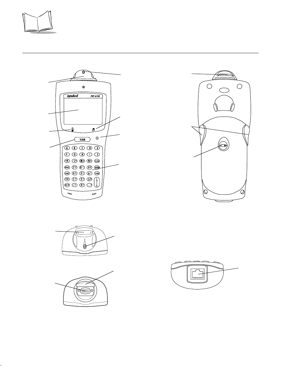
Parts of the PDT 6100 Series Terminal
Scanner
Dis pla y
Charging LED
Scan Bar
Scan Window
Front View
To p V i e w
Scan LED
Spectrum 24
Status LE D
Power Button
Key bo a rd
Scan LED
Scan Head
Scan Triggers
Battery
Compartment
Latch
Back View
DB9 Connector
1-2
SE 900 Scan Engine
DB9 Connector
Figure 1-1. Parts of the PDT 6100
DB9 Connector
Cover
Bottom View
Serial
Connector
Page 16
Getting Started
Accessories
The following accessories are available for the PDT 6100 terminal.
Battery Chargers
PDT 6100 Series terminals use rechargeable Nickel Metal Hydride (NiMH) battery packs.
NiMH batteries are charged using one of the charging accessories listed below.
Table 1-1. Battery Charging Accessories
Accessory Part Number
Single-Slot Cradle CRD 6100-1000
UBC 2000 6004-xxx
Charging and Communications
Cable (with power supply)
Four-Slot Cradle CRD 6100-4000 (not yet available)
25-33665-01
Scanners
The terminal uses:
integrated, standard-range, 1-D bar code scanner
!
external scanner with DB9 connector.
!
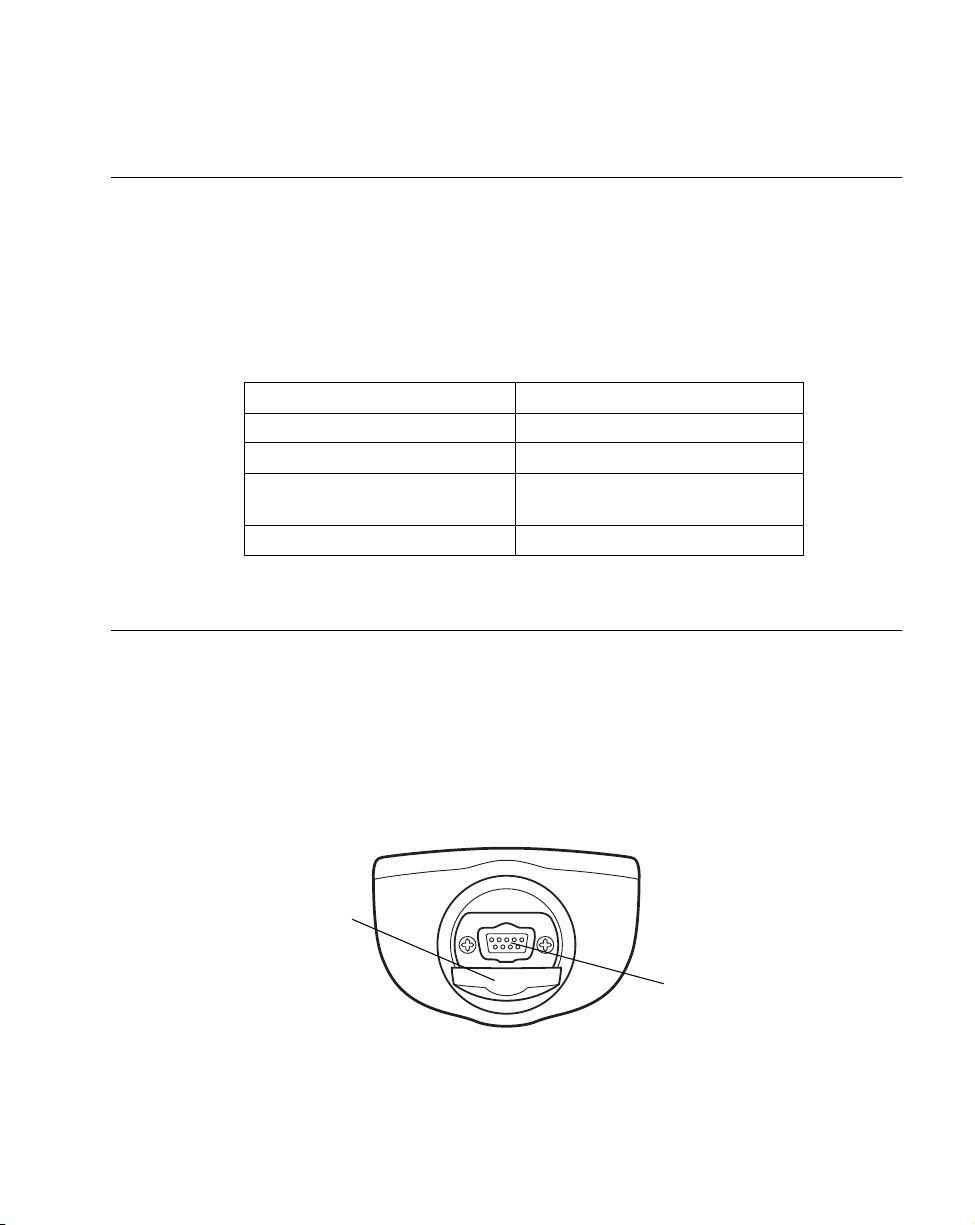
Connecting an External Scanner
Open DB9
Connector Cover
Figure 1-1. Connecting an External Scanner
Connect external scanner
cable to DB9 connector
1-3
Page 17

PDT 6100 Product Reference Guide
Radio and Network Options
Spectrum One® Network
The PDT 6110 includes an internal radio frequency transmitter/receiver for use in a Symbol
Spectrum One network.
Spectrum24® Network
The PDT 6142 and PDT 6146 include an internal radio frequency transmitter/receiver for use
in a Symbol Spectrum24 network.
Printers
The following printers can be used with the terminal:
Monarch Rascal
!
Monarch Renegade
!
ComTec 2-inch, 4-inch, and 6-inch receipt printers
!
Unpacking
Remove the clear protective tape from the display and the optical connector.
Save the shipping container for later storage or shipping. Inspect all equipment for damage
and make sure you have received everything listed on the packing slip.
If you find anything unsatisfactory or missing, contact your authorized customer support
representative immediately.
Miscellaneous Other Accessories
A holster and other terminal storing/carrying devices are available for use with the PDT 6100.
Before You Use the Terminal
Install and Charge Battery
Prior to using the PDT 6100 for the first time, install the NiMH battery. Be sure to charge the
battery before use. Refer to Chapter 6, Maintaining the Terminal.
1-4
Page 18

Load the Appropriate Software
What software you load and how you load it depends on several factors:
If this unit is intended for use in batch applications (6100) or in a Spectrum One
!
network environment (PDT 6110), refer to Chapter 3, Batch and Spectrum One
Terminal Setup for information on loading the software.
If this unit is intended for use in a Spectrum24 network environment (PDT 6142 or
!
PDT 6146), refer to Chapter 4, Spectrum24® RF Terminal Setup for general
information on Spectrum24.
Getting Started
1-5
Page 19

PDT 6100 Product Reference Guide
1-6
Page 20

Chapter 2
Installing the Hardware
Introduction
The CRD 6100 cradle is used for RS-232 communications, charging, and storing the PDT
6100 terminal.
This chapter provides information on setting up the cradle for charging the NiMH battery
and communicating with a host or other serial device.
Required Parts and Accessories
Verify that you have the following cradle parts, cables, and other kits/accessories before
attempting to mount or connect the cradle:
One-slot 61XX cradle with spare battery charging slot
!
RS-232 Null Modem Cable, DB-25 Male to DB-25 Female or DB-25 Male to
!
DB-9 Female
AC Power Supply (p/n 50-14000-086)
!
Power cord.
!
Save the shipping container for storing or shipping the cradle. Inspect all equipment for
damage. If anything is damaged or missing, call your authorized customer support
representative immediately.
2-1
Page 21
PDT 6100 Product Reference Guide
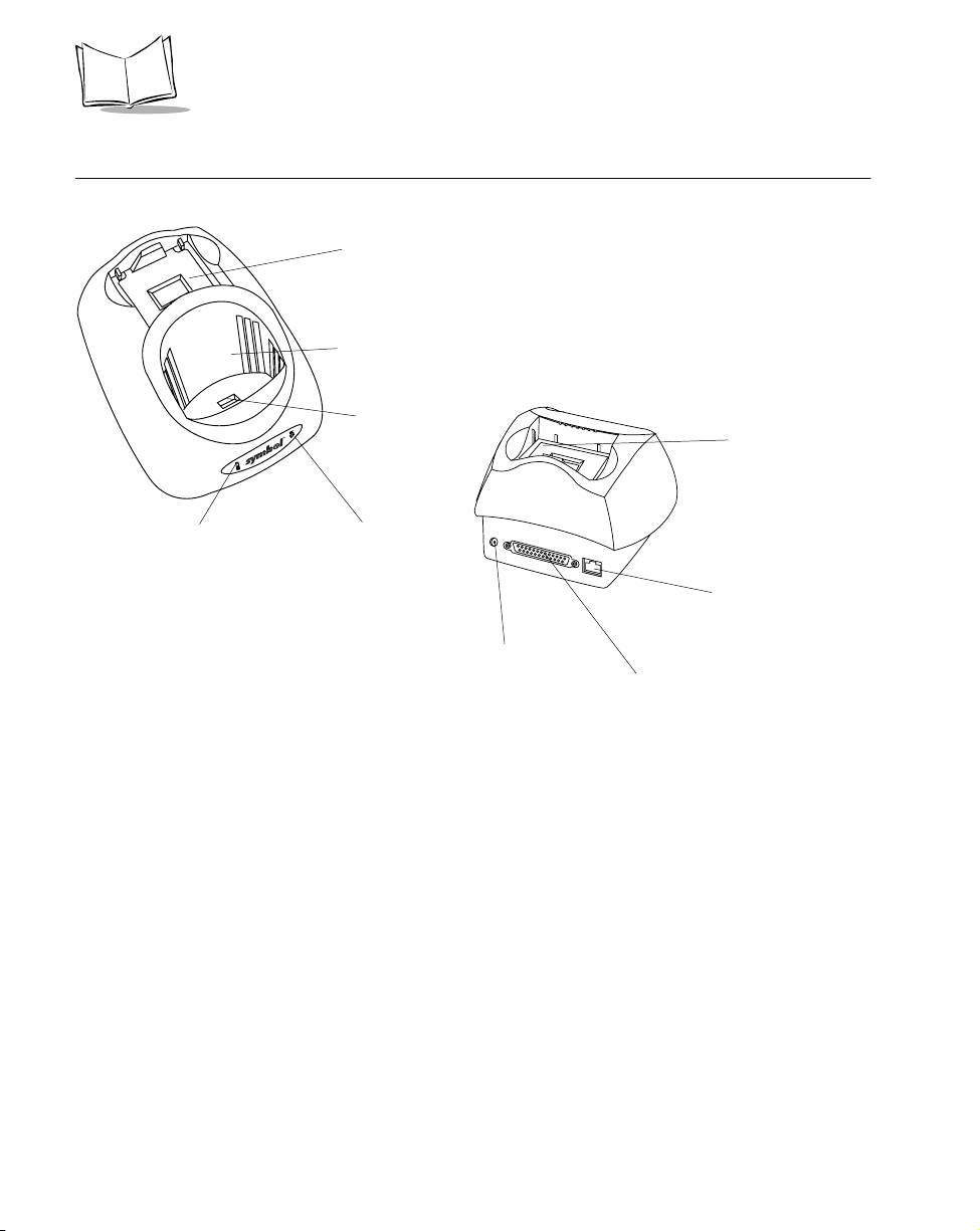
Parts of the Cradle
Spare Battery
Charging Slot
Te r m i n a l S l o t
RJ41
Connector
Spare Batter y
Charging Slot
Spare Battery
Chargin g LED
Front View
Communications
LED
AC Power
Conn ector
Back View
Figure 2-1. Parts of the Cradle
Modem Connector
(available as an option)
DB-25
Communications
Port
2-2
Page 22

Installing the Hardware
Connecting the Cables
To connect the CRD 61XX communications cables and power supply:
RJ-11 Modem Port
Power Jack
Figure 2-2. Connecting the Cables
1. Plug the RS-232 serial cable in the communications port located on the back of the
cradle.
2. Connect the serial cable’s other end to the host PC’s communications port.
3. Connect the power jack to the cradle’s AC power port.
4. Connect the power supply to a line cord.
5. Insert the line cord’s connector in a standard electrical outlet.
Serial Cable
Connecting the Internal Modem
Some cradles use an optional internal modem that communicates at rates of up to 14,400 bps
(with v.32 bit data compression). It can be connected directly to a telephone line through the
RJ-11 port shown in Figure 2-2.
The four-slot cradle does not have an internal modem.
Note:
2-3
Page 23

PDT 6100 Product Reference Guide
To connect the internal modem:
1. Connect the phone cord into the RJ-11 port on the back of the cradle.
2. Connect the other end of the phone cord into the wall phone jack.
Caution
When connecting the internal modem to the phone line, always connect the
phone line to the cradle first, then to the wall phone jack. When removing
the connection, always remove the telephone line from the wall phone jack,
then remove from the cradle.
There are specific firmware settings which are used to configure the modem’s hardware and
software for proper operation and regulatory compliance. The terminal’s application can
control these settings and enable you to view and amend the settings for country/region,
pulse/tone dialing, or repeat dial timing. Incorrectly defining these settings can lead to illegal
use of the modem and can create unreliable operation. The application developer should
consult the Series 3000 Application Programmer’s Reference Manual for correct settings.
Connecting to the Telephone Network
A compliant telephone cord is required with an RJ-11 plug connection to the modem,
terminated with an appropriate and correctly wired local telecom connector compatible with
the telephone network. Such a cable may be obtained from your local supplier. Alternately,
compliant RJ-11 plugs to RJ-11 plug cables may be used with a range of adapters for
locations such as Europe.
2-4
Page 24

Chapter 3
Batch and Spectrum One Terminal Setup
Introduction
Before using the PDT 6100 system, perform the following procedures:
Set up the CRD 6100 cradle (refer to Chapter 2, Installing the Hardware)
!
Install the battery (refer to Chapter 6, Maintaining the Terminal)
!
Charge the battery (refer to Chapter 6, Maintaining the Terminal)
!
Load the system files and application(s).
!
Hardware Requirements
Hardware required for performing initialization includes:
Host PC
!
RS-232 serial null modem cable
!
PDT 6100 terminal
!
Cradle with power supply.
!
Refer to Chapter 2, Installing the Hardware for setting up the cradle for communication.
3-1
Page 25
PDT 6100 Product Reference Guide
Communications
For terminals being used in a direct communications (batch) environment or a Spectrum One
network environment, applications are transferred from a host computer over a
communications line to the terminal.
This procedure uses the SENDHEX program on the host computer and the Program Loader
function (from Command Mode) on the PDT 6100.
Programs are stored in the terminal’s nonvolatile memory (NVM), also called the application
EEPROM.
For details on SENDHEX, refer to the Series 3000 Application Programmer's Manual.
Other software may be used in place of the SENDHEX program.
Set up for Initialization
1. Verify that the cradle is connected to the host PC. Refer to Chapter 2, Installing the
Hardware.
2. Place the PDT 6100 in the cradle (refer to Figure 3-1) and power it off.
3-2
33222011.eps
Figure 3-1. Placing the PDT 6100 in the Cradle
Page 26

Batch and Spectrum One Terminal Setup
Loading an Application
T o download an application, initiate the communications software on the host computer and
PDT 6100.
Note: To cancel communications at any time during the session, press
CLEAR on the PDT 6100. The session stops immediately.
Communication parameters specified on host and PDT 6100 must
match. These parameters typically are:
38400 bps
7 bit data
Odd parity
None
The PDT 6100 must be connected to the host through a cradle to
program the NVM.
Initiate Host Communications Software on the PC
1. Power on host computer.
2. Start the communication program.
3. At a DOS prompt, enter the SENDHE X comm a nd:
sendhex pgmname 38400 com2
where:
SENDH E X is the command.
pgmname is the application being loaded (.hex extension is optional).
parameters are the communications parameters following the program name.
Parameters include baud rate, communications port, data bits, parity,
and flow control . To accept the defau lt param eters, d o not enter a value.
In the example, baud rate is set to 38400 bps and communications port to COM2.
The default values are accepted for the remaining parameters.
3-3
Page 27

PDT 6100 Product Reference Guide
Note: Versions of SENDHEX earlier than 3.0 do not support flow control.
If you use an earlier version and encounter communication errors, use
a lower baud rate. If you use a later version of SENDHEX and have
communications errors, try setting flow control to XON/XOFF.
4. SENDHEX displays the prompt:
Press <ENTER> to begin
commun ica tions .
5. Do NOT press <ENTER> yet. Before starting communications (refer to Starting
Communications on page 3-6), set up the PDT 6100 for loading a HEX image as
directed in the following sections.
Initiate Terminal Communications
1. Boot the PDT 6100 to command mode.
For the 22-Key terminal:
" Press and hold <SEND> and <9>.
" Press and release PWR.
" Release <SEND> and <9>.
For the 35-Key terminal:
" Press and hold <BKSP> and <SHIFT>.
" Press and release PWR.
" Release <BKSP> and <SHIFT>.
For the 46-Key terminal:
" Press and hold <F> and <I>.
" Press and release <PWR>.
" Release <F> and <I>.
The display shows the function selector screen:
COMMAN D M ODE
Select func tion
Self Test
3-4
Page 28

Batch and Spectrum One Terminal Setup
2. Scroll through Command Mode options u sing UpArrow or DownArrow until
“Program loader” is displayed. Press <ENTER>.
3. The PDT 6100 displays:
Progra m l oader
WARNIN G: NVM
WILL BE ERASED
CONTINUE? <ENT>
Before loading the new application, erase NVM’s original contents.
To cancel this operation, press <CLEAR>.
Note:
4. Press <ENTER> to erase the NVM.
Wait while the NVM is erased. When complete, the program prompts for the
communications parameters.
5. Baud Rate.The PDT 6100 displays:
Comm Parameters
Baud
5 38400
Scroll through the list using UpArrow or DownArrow. When the correct rate is
displayed (38400 is recommended), press <ENTER>.
6. Data Bits. The PDT 6100 displays:
Comm Parameters
Data Bits
7
Press <7> (recommended) or <8> to specify data bits, or scroll through the list using
UpArrow and DownArrow. Press <ENTER> when the correct value is displayed.
Note: If 8 data bits is selected, the program selects “No parity” and skips
the next step.
3-5
Page 29

PDT 6100 Product Reference Guide
7. Parity. If 7 data bits is selected, the PDT 6100 displays:
Comm Parameters
Parity
Odd
Press the first letter of a parity option (Even, Odd, None, Space, or Mark), or scroll
using UpArrow and DownArrow and press <ENTER> when th e correct value is
displayed.
8. Flow Control. The PDT 6100 displays:
Comm Parameters
Flow Control
None
Press the first letter of a flow control option (None, Xon/Xoff, or RTS/CTS), or scro ll
using UpArrow or DownArrow and press <ENTER> when the correct value is
displayed.
9. Go to Starting Communications to continue.
Starting Communications
The PDT 6100 is ready to receive the program from the host PC and displays:
Comm Parameters
Start? <ENT >
1. Press <ENTER> on the PDT 6100. The PDT 6100 waits a few seconds for the host
PC to initiate communications. While waiting, the PDT 6100 displays:
Comm Parameters
Receiv ing :
If the host is not ready or the cable is not connected between the host PC and cradle,
the terminal d is p lays:
Awaiti ng DSR
3-6
Page 30

Batch and Spectrum One Terminal Setup
2. Press <ENTER> on the host computer. SENDHEX begins transmitting the program
image. When communications are established, the PDT 6100 displays:
Progra m l oader
Receiv ing : XX XX
where XXXX is the program segment address being transferred.
3. When the transmission is complete, the PDT 6100 displays:
Progra m l oader
Status 0000
A status of 0000 (all zeros) indicates a successful transfer. Other status values
indicate an error. These val ues are p rovid ed in Appendix C, Communications Status
Codes.
Ending Communications
To return to the Command Mode main menu:
1. Press <CLEAR> on the PDT 6100.
2. Power down the PDT 6100.
3. Remove the PDT 6100 from the cradle.
4. Reboot the PDT 6100 using the appropriate cold boot sequence described in Booting
the Terminal on page 5-4.
3-7
Page 31

PDT 6100 Product Reference Guide
3-8
Page 32

Chapter 4
Spectrum24
®
RF Terminal Setup
Spectrum24 Terminals
In Spectrum24 terminals, wireless connectivity is accomplished using standard
communications protocols. Because they are standard, the protocols are generalized and take
up considerably more space on the terminal’s NVM than is required for Spectrum One
terminals. Because there is less space available in NVM for application files, the terminal
operates with an additional megabyte of non-volatile memory or flash disk. This extra
memory is used to reduce not only the boot times but also the time and resources required to
load applications into the terminal. The flash disk also offers the possibility of running
multiple applications from the same terminal (re fer to the Spectrum24 Terminal Setup and
Utilities Reference Guide p/n 72-50795-01 for more information). With version 3.03 or later
of the system software (LWP.HEX), the terminal can also run diagnostic tools.
Accessing the Flash Disk
The flash disk is accessed through a driver, FLASHDSK.SYS, which makes th e flash disk
appear to a program as another disk drive (E:). The drive has characteristics of fast reading
but slow writing (for example, even for the smallest files, the write process takes 3-4 seconds).
These characteristics make it ideal for files that are written once, accessed often, and seldom
updated.
®
We recommend that you use the flash disk (E:) mainly for application and configuration file
storage. It is important to note that because of the slow writing time (3-4 seconds), writing
files during a power interruption (low battery, dead battery, suspend, pow er off, o r power
failure) could corrupt the disk. Be sure to o n ly write data to the disk with the terminal
connected to external power or with the battery fully charged to avoid problems. To avoid
overwriting the flash disk by mistake, the flash di sk is set t o read-only mode for normal
operation. The softwa re installation or application software takes care of write/read mode
switching for you.
4-1
Page 33

PDT 6100 Product Reference Guide
Standard Spectrum24 Software
The terminal comes with the system software installed, including:
Spectrum24 radio dri vers
!
TCP/IP software
!
configuration files
!
various utilities.
!
A BIOS of versi on 3.08 or later is required.
The default files c over most expected installatio ns/initializations with minor changes a s
detailed in this chapter.
If your requireme nts are more advanced, refer to the Spectrum24 Network Terminal
Technical Reference Guide (p/n 70-20193-XX) for more information on the Spectrum24 RF
netwo rk , S LA ODI .COM , t he Sy mbo l- pr ov ide d ODI dr iv er, a nd t he con fig ur at i on fi l e se tups
requ ired for various platforms.
Refer to the Spectrum24 Terminal Setup and Utilities Reference Guide (p/n 72-50795-XX)
for more information on Spectrum24 boot options, addressing, initializing the terminal, and
Access Point (AP) associations.
4-2
Page 34

Chapter 5
Operating the PDT 6100 Series
Introduction
This chapter describes how to operate a PDT 6100 terminal, including:
Powering the terminal on/off
!
Boo ting the term i nal
!
Adjusting the display’s contrast
!
Entering data using the keyboard
!
Entering data through the integrated scanner
!
Communicating with other devices using the Charging and Communications Cable.
!
5-1
Page 35

PDT 6100 Product Reference Guide
Powering a Terminal On and Off
Because the terminal is battery powered, it is important to save power whenever possible. You
can minimize power loss and increase battery life by turning the terminal off when data is not
being entered.
While the terminal’s processor and display are off, programs or data in the system's memory
are retained. Before the terminal powers up, it checks the batteries for enough power to
ensure reliable operation and data storage. Power-up restores the display, and processing
continues from where it was before power-down.
Powering the terminal on does not boot the system or initialize either the program or data.
For more information on initialization, refer to Chapter 3, Batch and Spectrum One Terminal
Setup.
Normal Power
Charge the NiMH battery before use!
Note:
To power the terminal on or off, press < > (PWR).
Automatic Power
Depending on the application, a number of other events may turn a terminal on or off.
Power O n
The system powers on when a key other than < > (PWR) is presse d .
!
The system powers on when a scanner trigger is pressed.
!
The program powers on the system at a preset time to perform unattended
!
operations, such as an overni ght communications session.
The program powers on the system in response to a modem ring or an RS-232 device
!
connected to the RJ connector.
Power O f f
If not used for a specific period of time, as determined by the application, the system powers
off automatically to conserve power.
5-2
Page 36

Operating the PDT 6100 Series
Forcing Power Off
If a terminal freezes in the middle of operation and pressing < > (PWR) does not power it
off, you can force the system to power off, which reduces the drain on the batteries until you
can download any collected data to the host system.
To force the system to power off, press and hold < > (PWR) for 15-20 seconds.
Since the terminal is still frozen at this time, turning the power back on does not solve the
problem. To recover the data held in mem ory, perform a Warm Boot (refer to Booting the
Terminal on page 5-4).
Restarting After a Forced Power Off
If an operator is forced to power down a terminal because of defective software, the System
Administrator should restart the system using the warm or cold boot procedures in the
follo w ing sec t ion.
Note: Do not use the power key to restart if the terminal was forced off due
to defective system or application program software in NVM.
Pressing < > (PWR) only causes the program to resume where it left
off, trying to perform the same unsuccessful operation.
5-3
Page 37

PDT 6100 Product Reference Guide
Booting the Terminal
Powering the terminal on does not boot the system or initialize the program or data. To
initia lize the te rm inal, perform either a warm or cold boot.
Warm Boot
A warm boot resets the operating system while preserving the program and data on the RAM
disk. This process is similar to pressing the <Ctrl+Alt+Del> keys on a PC, except that it does
not clear the system's memory. To perform a warm boot:
For the 22-Key terminal:
" Power the terminal off
" Press and hold Down Arrow and Period
" Press and release <PWR>
" Release Down Arrow and Period.
For the 35-Key terminal:
" Power the terminal off
" Press and hold <F> and <J>.
" Press and release <PWR>.
" Release <F> and <J>.
For the 46-Key terminal:
" Power the terminal off
" Press and hold <4> and <5>.
" Press and release <PWR>.
" Release <4> and <5>.
The terminal displays a copyrig h t mes s age, RAM size, expand ed memory RAM size, etc.,
depending on the s ys t em's configuration. Other information display ed depends on the
operating system, installed device drivers , and AUTOEXEC.BAT commands. If this warm
boot procedure fails to restart the termin al, use the Cold Boot procedure.
Note: If the batteries are replaced and the supercap is discharged, the
terminal cold boots.
5-4
Page 38

Operating the PDT 6100 Series
Cold Boot
A cold boot fully resets the system and clears memory, including the RAM disk. Any
programs and data stored in memory or on the RAM disk are deleted. Nonvolatile memory
(NVM — the Application EEPROM) is not affected. If the cold-boot procedure fails to restart
the terminal, refer to Chapter 7, Error Recovery and Troubleshooting.
Caution
This procedure permanently erases all data and software in the terminal unless they reside in NVM. Contents of RAM are lost.
To perform a cold boot:
For the 22-Key terminal:
" Power the terminal off
" Press and hold Up Arrow, <4>, and <ENTER>
" Press and release <PWR>
" Release Up Arrow, <4>, and <ENTER>.
For the 35-Key terminal:
" Power the terminal off
" Press and hold <SPACE>, <FUNC>, and Up Arrow
" Press and release <PWR>
" Release <SPACE>, <FUNC>, and Up Arrow .
For the 46-Key terminal:
" Power the terminal off
" Press and hold <A>, <B>, and <D>
" Press and release <PWR>
" Release <A>, <B>, and <D>.
The terminal displays version information, copyrigh t, RAM size, and installed expanded
memory RAM size. Other information displayed depends on the operating system, installed
device drivers, and AUTOEXEC.BAT commands.
5-5
Page 39

PDT 6100 Product Reference Guide
Cold-Boot Failure
During a cold boot, the system briefly displays a status line for each driver as it loads in the
format:
0: Driver #.##
The line shows a status value, usually 0, followed by the name and version number of the
driver. If the sy ste m halts at one of these lines and displays a status value other than 0, the
displayed device driver failed to load properly.
If such a failure occurs, try cold booting the terminal again. If this does not solve the problem,
call the Symbol Support Center.
More troubleshooting information is provided in the publications listed in Related
Publications at the beginning of this manual.
Boot to Command Mode
Command Mode provides functions for:
Running the Self-Test program to verify that the hardwar e is operating properly
!
(refer to Chapter 7, Error Recovery and Troubleshooting).
Performing a Memory Transfer to upload data from a terminal to a host system (refer
!
to Chapter 7, Error Recovery and Troubleshooting).
Performing a Program Download to transfer an application from the host to a
!
terminal (refer to Chapter 3, Batch and Spectrum One Terminal Setup).
To boot to Command Mode:
For the 22-Key terminal:
" Power the terminal off
" Press and hold <SEND> and <9>.
" Press and release <PWR>.
" Release <SEND> and <9>.
For the 35-Key terminal:
" Power the terminal off
" Press and hold <BKSP> and <SHIFT>.
" Press and release <PWR>.
" Release <BKSP> and <SHIFT>.
5-6
Page 40

Operating the PDT 6100 Series
For the 46-Key terminal:
" Power the terminal off
" Press and hold <F> and <I>.
" Press and release <PWR>.
" Release <F> and <I>.
Adjusting the Display
Backlighting
The terminal’s backlight illuminates the display in dimly lit areas.
Use of backlighting can significantly reduce battery life.
Note:
To turn the backl ight on or o ff, press the following keys in sequence:
<Func> then <L> (Lam p)
The backlight also turns off when a terminal is powered off or when a timeout set by the
application occurs.
Display Contrast
The LCD display contrast is adjustable, making the display more readable in different
lighting conditions, at various temperatures, with different attachments, and at other viewing
angles.
To increase contrast (darken) by one step, press the following keys in sequence:
<Func> then <X>
To decrease contrast (lighten) by one step, press:
<Func> then <Z>
5-7
Page 41

PDT 6100 Product Reference Guide
PDT 6100 Series Keyboard
The keyboard is used for entering data and issuing commands to the terminal. Figure 5-1,
Figure 5-2, and Figure 5-3 illustrate the standard 22-key, 35-key , and 46-key keyboards
respectively. Refer to Appendix B, Keyboard Layouts for more information.
The keys on the keyboard are distinguished as modifier keys and character keys. Because
terminal keyboards have fewer keys than PC keyboards, each character key can produce
more than the usual one or two characters. The four modifier keys, Shift, Alpha, Ctrl, and
Func, used individually or in combination, determine which character or special function the
character keys produce.
Using the Keyboard
Except for during boot operations, the t erminal expects the operator to press keys one at a
time. If ERR3000 is loaded, and if two or more keys are pressed simultaneously, the system
indicates a Double Key error.
The keyboard also has an optionally configurable auto-repeat function. If the application
allows, a charac ter repeats as long as the key is held down. If the key is pressed immediately
following a modifier key, the modifier sequence affect s only the first occurrence of the
character key.
5-8
SCAN
FUNC BACK
SEND CLR
-
789
4
1
,
5
2
0
6
3
.
E
N
T
E
R
Figure 5-1. PDT 6100 Standard 22-Key Keyboard
Page 42

Operating the PDT 6100 Series
Figure 5-2. PDT 6100 Standard 35-Key Keyboard
SCAN
ABC
CTL
F
E
I
J
O
P
U
V
G
K
L
Q
R
W
X
789
456
CLR
D
H
M
N
S
T
Y
Z
FNC
SHF
BSP
123
.
ENTER
0
Figure 5-3. PDT 6100 Standard 46-Key Keyboard
5-9
Page 43

PDT 6100 Product Reference Guide
Modifier Ke y s
The Shift, Alpha, Function, and Control keys are modifier keys. When pressed indiv idually
or in certain combin atio n s, these keys change the keyboard stat e and possibly the c haracter
produced by the character key subsequently pressed.
For example:
Pressing <Alpha> causes the numeric keys to produce letters.
!
Pressing <Func> followed by <Ctrl> produces Alt characters, with the same effect as
!
pressing the Alt key on a PC.
Pressing <Func> and a scanner trigger enables that trigger for scanning. Refe r to the
!
section Scanning on page 5-12 for more information.
The opposite trigger is another Alpha key (Al pha Shift), producing capital letters. It
!
is active only when held down.
The <Alpha> key on the keyboard affects all succeeding character keys until <Alpha>
!
is pressed again. The other modifier keys affect only the next character key.
Refer to Appendix B, Keyboard Layouts for the characters and operations produced by
pressing a sequence of modifier keys on the standard terminal keyboards. These key
assignments can be changed by an application. Refer to your application documentation for
any special key assignments.
Cancelling a Modifier Key
To cancel the effect of a modifier key, press it again.
Keyboard State
The cursor’s shape indicates the current keyboard state, unless changed by the application.
The standard cursor shapes are shown in Table 6-2 on page 6-3.
Key Descriptions
Most of the keys are s elf-explanato ry. Letter keys produce letters, number keys produce
numbers. Keys that perform special functions are described in Table .
5-10
Page 44

Table 5-1. Sp ecial Keys
Operating the PDT 6100 Series
22-Key
Key Name
FUNC FUNC
35-Key
Key Name
CTRL
(Control)
(Function)
46-Key
Key Name
CTL
(Control)
FUNC
(Function)
Description
Invokes the control command.
Invokes the function command for certain utilities,
such as turning on the back light.
" Press FUNC and the corresponding numeric key to
produce function keys F1 to F10.
" Press FUNC, then to scroll left and FUNC to scroll
right.
" Press FUNC then BKSP to enter a blank space.
BACK BKSP
(Backspace)
PWR
(Power)
CLEAR CLR (Clear) Partially or completely escapes from an application
SHIFT SHF (Shift) Accesses the shifted keyboard.
ENTER ENTER ENTER Places entered data into the terminal’s memory.
BKSP
(Backspace)
PWR
(Power)
Erases information entered on the display one
character at a time. Information erased this way
cannot be recovered. This key is also used to produce
a break by pressing CTL, BKSP.
Turns the t erminal on and of f.
level or screen. CLR also clea rs all data typed fr om the
display.
Move the cursor up, down. Press FUNC then to
scroll left; press FUNC then to scroll right. Arrow
key use depends on the application.
Moves the cursor up, down.
Move the cursor left, right.
ALPHA Shifts the keyboard to produce alphabetic characters.
SPACE Places a blank space on a line of the display.
SEND Allows you to send data to the host.
5-11
Page 45

PDT 6100 Product Reference Guide
Scanning
Before scannin g can occur, the application must implement routines to support bar code
scanning. Fo r information on scanning applications and on programming the scanner, refer
to the Series 3000 Application Development Kit.
The PDT 6100 terminal supports an integrated 1-D standard scanning device.
Setting the Trigger
The integrated scanner has a unique trigger that the operator can configure. To use the
integrated laser scanner:
1. Power on the system and scanner by pressing < > ( PWR) or the scanner trigger.
2. Lift up and turn the scan element on the top of the terminal to the preferred
orientation for scanning (refer to Fig ure 5-4). The scan head turns only toward the
back of the terminal.
Figure 5-4. Positioning the Integrated Scanner
3. Lock the scan head in position, facing the side of the terminal.
4. T o select the trigger , press the <FUNC> key and the trigger you are most comfortable
using. The other trigger defaults to an ALPHA shift key. Depending on the
application, the terminal m ay beep t o in dicate a t r ig ger is selec te d.
5-12
Page 46

Operating the PDT 6100 Series
Using the Integrated Laser Scanner
To scan:
1. Power on the system and scanne r by pressing the < > ( PWR), the SCAN bar, or a
trigger. The Scan LED lights yellow if scanning is enabled and the laser is on.
2. Turn the scanner to the direction you wish to scan. The scanner turns toward the
back of the 6100.
3. Point the PDT 6100 at the bar code and press the scan bar or a side trigger.
Figure 5-5. Scanning a Bar Code
4. Ensure that the scan beam crosses all bars and spaces on the symbol, as shown below .
Right Wrong
5. Hold the scanner farther away for larger symbols, and closer for symbols with bars
that are close together.
6. The LED turns from yellow to green for successful decodes. The PDT 6100 may also
beep.
5-13
Page 47

PDT 6100 Product Reference Guide
Aiming: Hold at an Angle
Do not hold the 6100’s scan window directly over the bar code. Laser light reflecting directly
back into the scan window from the bar code is known as specular reflection. This strong
light can “blind” the scanner and make decoding difficult. The area where specular reflection
occurs is known as a “dea d zone”.
You can tilt the 6100 up to 55° forward or back and achieve a successful decode. Practice
quickly shows what toleran ces to work within.
Figure 5-6. Scanning Angle and Specular Reflection
Range
Any scanning de vic e decodes well ove r a parti cular w orki ng range — minimum an d
maximum distances from the bar code. This range varies according to bar code density and
scanning device optics.
Scanning within range brings quick and constant decodes; scanning too close or too far away
prevents decodes. You need to find the right working range for the bar codes you are
scanning. The best general advice is:
Hold the scanner farther away for larger symbols.
!
Move the scanner closer for symbols with bars that are close together.
!
Start scanning at a distance from the bar code — not from direct contact. If the bar
!
code does not readily decode, move the scanner in closer.
5-14
Page 48

Operating the PDT 6100 Series
The best way to specify the appropriate working range is through a chart called a Decode
Zone (Figure 5-7). A decode zone simply plots working range as a function of minimum
element widths of bar code symbols.
Note: Typical performance at 68 F (20 C)
on high quality symbols.
SE 900
STANDARD
5 mil
2.2
1.8
2.0
4.8
7.5 mil
6.2
100% UPC
20 mil
*
*
*
40 mil
55 mil
13.0
20.0
25.0
26.0
In. cm
15
10
5
0
5
10
15
38.1
25.4
12.7
0
12.7
25.4
38.1
W
i
d
t
h
o
f
F
i
e
l
d
In.cm0
5
0
12.71025.41538.12050.82563.53076.2
Depth of Field
Minimum distance determined by symbol length and scan angle
*
Figure 5-7. PDT 6100 Decode Zone
5-15
Page 49

PDT 6100 Product Reference Guide
Running Communications
Communicating with a Host
The 6100 communicates with a host or printer through the CRD 6100 or the Charging and
Communications Cable (CCC).
To communicate with a host or printer through the CRD 6100:
1. Set up the cradle as described in Connecting the Cables on page 2-3, or in the CRD
6100 Quick Reference Guide.
2. Place the 6100’s base in the cradle. Press the top of the 6100 against the cradle back
until it is firmly seated.
The terminal’s Charging LED flashes yellow and then lights solid yellow when the
terminal is securely placed in the cradle.
3. Start the communications program on the host and the 6100.
5-16
33222011.eps
Figure 5-8. PDT 6100 Seated in CRD 6100
Page 50

Operating the PDT 6100 Series
To communicate with a host through the CCC (refer to Figure 5-9):
1. Plug the CCC‘s 10-pin RJ41 connector in the 6100’s base.
2. Connect the DB-9 connector to the host’s serial (COMM) port.
3. Start the communications program on the host and the 6100.
CCC
DB-9
Connector
RJ41
Connector
Figure 5-9. Using the CCC to Connect the PDT 6100
to a Host PC (shown) or Printer
33222013.eps
Radio Communications
The PDT 6110 operates in a Symbol Spectrum One RF network; the PDT 6140 operates in
a Symbol Spectrum24 RF netw ork.
The Status LED indicates the state of the 6100’s connection t o either of the RF networks:
Off indicates that the radio is working and associated with an access point
(Spectrum24) or base station (Spectrum One).
(The Status LED indication of RF activity is presently not available.)
Flashing green
once per second
Refer to the network documentation for more information on operating the PDT 6100 in the
specific RF environment.
indicates that the radi o is out of range or not assoc ia ted with a n access point or
base station.
(The Status LED indication of RF activity is presently not available.)
5-17
Page 51

PDT 6100 Product Reference Guide
Communicating With a Printer
To connect the terminal to a prin ter, use the CCC or the appropriate prin ter cable. The
following directions apply to the CCC:
1. Plug the CCC’s 10-pin RJ-41 connector into the PDT 6100 terminal’s serial port
(refer to Figure 5-9).
2. Plug the DB-9 connector in the communications port on the printer.
3. Start the communications program.
5-18
Page 52

Chapter 6
Maintaining the Terminal
Batteries
The PDT 6100 terminal’s primary power is provided by a nickel metal hydride (NiMH)
battery pack.
Battery Life
Many factors affect battery pack life, including temperature, battery age, and data collection
method. Uses and operating conditions which affect battery life are:
scanning
!
“power save” mode
!
radio commun ications
!
backlighting
!
very high operating temperatures
!
very low operating temperatures.
!
The approximate battery life between charges is summarized in Table 6-1. Note that these
values vary with the application. Applications involving radio communications shorten these
times.
6-1
Page 53

PDT 6100 Product Reference Guide
Table 6-1. Battery Life: PDT 6100
Battery Type Input Method Approx. Operating
Time: PDT 6100
1500 mAh NiMH Keyboard 50 hou rs 45 hou rs 48 hour s
Laser Scanner 6400 + scans 6100 + scans 6200 + scans
Radio N/A 7.5 hours 10 hours
* Power consumption is highly application-dependent. The figures above represent battery life of
typical applications. However, battery life with individual applications will vary.
Approx. Operating
Time: PDT 6110
Approx. Operating
Time: PDT 614X
When to Replace or Recharge Batteries
The terminal provides two types of indicators to notify you when batte ry power is running
low: warning messages and modified cursors. These indicators may be changed or disabled
by an application program.
LOW POWER — When the batt ery is low, the cursor cha n g es as shown in
!
Table 6-2 If ERR3000 is loaded, the message LOW BATTERY also appears. At this
level, the terminal continues to operate , but there is probably less than 1 hour of
usable power left.
VERY LOW — When the power is very low, the DEAD BATTERY message appears
!
and the system powers off. Replace or recharge the battery before attempting to use
the terminal. If the battery is not immediately recharged or replaced, data may be
lost.
Battery life var ies between 500 - 1000 charge / discha rg e c yc les. This variation depends on
the depth of discharge. In general, replace batteries which exhibit less than 80% of their total
rated capacity.
6-2
Page 54

Maintaining the Terminal
Table 6-2. Cursor Indicators
33222010.eps
Supercap Power Backup
To prevent data loss during battery replacement, the terminals have a supercap power
backup. The supercap backup provides sufficient power to preserve mem ory contents for
approximately 15 minutes while batteries are replaced. The supercap does not provide
enough power to operate the terminal. On receiving a low battery message, replace or
recharge the pr imary batteri es immediately.
Replacement Batteries
A rechargeable 1500 mAh NiMH b attery pa ck, p/n 21-33061-01, can be ordered from
Symbol Technologies.
6-3
Page 55

PDT 6100 Product Reference Guide
Installing a New or Recharged Battery Pack
To install a new or recharged NiMH battery:
1. Turn the battery pack latch counterclockwise and remove the battery compartment
door.
Figure 6-1. Removing the Battery Compartmen t Door
2. Lift the battery pack out.
3. Slide a NiMH battery pack in the compartment, with the contacts facing inside the
compartment and the tab facing the top of the compartment (Figure 6-2).
6-4
Ta b
Contacts
Figure 6-2. Inserting the NiMH Battery Pack
Page 56

4. Replace the battery compartment door (Figure 6-3).
Figure 6-3. Replacing th e Battery Compartment Door
5. Turn the latch clockwise to secure the battery.
Charging the Battery
Using the CRD 6100
To charge the NiMH battery in the PDT 6100:
1. Seat the PDT 6100 in a CRD 6100 connected to a powe r sour ce.
Maintaining the Terminal
Figure 6-4. S e a ting the PDT 6100 in the CR D 6100
2. The PDT 6100’s Charging LED flashes yellow at the start, lights solid yellow while
the battery is charging, and lights solid green when the battery is fully charged.
The charging time required is approximately 2.5 hours.
6-5
Page 57

PDT 6100 Product Reference Guide
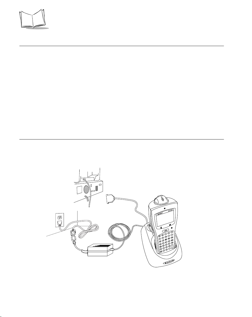
Using the CCC
The optional CCC provides power from a wall-mounted power supply for recharging the
NiMH battery while the 6100 is in use.
To connect the 6100 and the CCC:
1. Plug the CCC’s 10-pin RJ41 connector in the 6100’s base.
2. Plug the connector from the 12V power supply in the CCC’s power input jack (power
supply p/n 50-14000-086).
3. Connect the power supply’s connecto r to a power lin e cord.
Figure 6-5. Connecting the CCC
4. Connect the power line cord to a wall outlet.
Batteries recharge in 2.5 hours.
6-6
33222013.eps
Page 58

Maintaining the Terminal
Recharging a Spare Battery Pack
To recharge a spare b attery pack in the cradle:
1. Insert the battery pack sideways, contacts down, into the spare battery slot, with the
tab facing either the right or left side of the cradle.
2. Angle one side of the battery under the lip on the cradle’s well.
3. Press down on the other side of the battery until the latch catches.
Latch
Battery
Ta b
Charging LED
Lip on cradle well
Figure 6-6. Charging a Spare Battery Pack
The cradl e’s Charging LED flashes yell ow when the battery is first insert ed. The LED
lights solid yellow to indicate the spare battery is charging, and switches to solid
green when the battery is charged. The spare battery recharges in 2.5 hours.
4. Remove the spare battery and place it in the PDT 6100, or leave it in the cradle for
temporary storage.
To remove the battery, grip on either side of the battery and lift it out of the charging
slot.
Note: The spare battery can be inserted with the tab pointing to either side
of the cradle well.
Other Charging Options
The NiMH battery pack can be charged in the UBC 2000 Charger. See instructions provided
with the charger for more information.
6-7
Page 59

PDT 6100 Product Reference Guide
Battery Charging Tips
For maximum capacity and battery life:
Charge at temperatures between 0oC and 40oC (32oF and 104oF). Optimum
!
charging occurs at room temperature (about 20
range, batteries may not charg e to rated capacity.
Recharge as soon as you see the "Low Battery" message.
!
Charge NiMH batteries after storage.
!
o
C to 25oC). Above or below that
Cleaning
The terminal requires a minimum amount of maintenance. However, keep the terminal clean
to avoid problems and prolong the terminal’s life.
Before doing any maintenance or cleaning, power the terminal off.
To clean a terminal, use a clean, soft cloth dampened with a mild cleaner such as soap and
water. Do not use abrasive paper, cloth, or abrasive/corrosive cleaners.
Wipe the entire terminal, except for the scanner window, with the damp cloth. Clean the
keypad and scanner triggers.
Wipe the scanner window periodically with a lens tissue or other material suitable for
cleanin g optical ma t erial su ch a s e y eglasses .
Caution
Do not pour, spray, or spill any liquid onto any part of the terminal, particularly the scanner or scan element components.
Storage
If the terminal will not be used for a while, store it in a cool, dry place, away from dust. For
the best protection, repack the terminal in the original shipping container for storage.
Caution
If you remove the primary battery , the terminal maintains memory contents
for at least 15 minutes. T o prevent loss of programs and data, transmit them
6-8
Page 60

Maintaining the Terminal
to a host computer before removing the primary batteries for longer than 15
minutes.
When you remove the terminal from storage without the battery pack, reset the real time
clock. Refer to the Series 3000 Application Programmer’s Reference Manual or Series 3000
Application Programmer’s Guide for specific instructions.
6-9
Page 61

PDT 6100 Product Reference Guide
6-10
Page 62

Chapter 7
Error Recovery and Troubleshooting
Introduction
This chapter provides information to assist in basic trouble analysis and correction for the
PDT 6100, including:
Error messages
!
Troubleshooting start-up failures
!
Troubleshooting Spectrum24 terminal initialization failures
!
Running the self test function
!
Self test summaries
!
Keyboard test
!
Running memory transfer
!
Scanning problems.
!
Error Messages
If ERR3000 is loaded in the system configuration, the terminal displays the following
messages to indicate error conditions that affect system performance. A message is usually
accompanied by one or more beeps, after which the system returns to its previous statu s.
The application can change the actual word ing of the messages or disable messages. The
messages listed in Table 7-1 are representative. Refer to the Series 3000 Application
Programmer's Guide or your application guide for additional information.
7-1
Page 63

PDT 6100 Product Reference Guide
Table 7-1. Error Messages
Message Explanation
Double Key Error Two or more keys were pressed at the same time. This does
not include boot sequences (refer to Chapter 5, Operating
the PDT 6100 Series, for boot sequences).
Low Battery The battery p ack shoul d be recha rged or replaced as soon as
possible.
Dead Battery Replace or rechar ge the b attery pac k imme diately. After th is
message is displayed, the system shuts off. You may not be
able to power it on again until the battery pack is charged.
Power Fault The last power off was caused by a power failure. This
occurs, for exampl e, if t he bat tery pack is r emoved whi le the
terminal is on or the batteries fail suddenly.
Troubleshooting
Start-up Failure
Problems are most frequently start-up failures. If cold booting the terminal does not start the
application successfully, either the application, the system software, or the system is
malfunctioning. If you can boot the system to command mode, try the following:
Use Program Loader to download a new version of the software to NVM. This
!
procedure is described in Chapter 3, Batch and Spectrum One Terminal Setup for
batch or Spec trum One terminals, or Chapter 4, Spectrum24® RF Terminal Setup
for Spectrum24 terminals.
Use Self Test to check whether system hardware is operational. The Self Test
!
procedure is described later in this chapter. After downloading new software, warm
boot the terminal as described in Chapter 5, Operating the PDT 6100 Series.
Boot Failure Messages
During a cold boot, the system briefly displays a status line for each driver as it loads, in the
format:
0:Driv er # .##
7-2
Page 64

Error Recovery and Troubleshooting
The line shows a status value, usually 0, followed by the name and version number of the
driver. If the s ystem halts at one of these lines and displays a status value other than 0, the
displayed device driver did not load properly.
If such a failure occurs, cold boot the terminal again. If this does not solve the problem, call
Symbol Customer Support.
More troubleshooting information is found in the documentation listed in Related
Publications.
Spectrum24 Terminal
The command mode troubleshooting procedures utilized by 6100 batch or Spectrum One
terminals are not available to terminals operating in a Spectrum24 network environment.
Ty pical initialization and operating problems and solutions for Spectrum24 terminals are
listed in Table 7-2.
Table 7-2. Troubleshooting Spectrum24 Terminals
Problem Explanation/Action
Out of r ange Terminal is out o f th e Access Point’s range.
If you move the terminal during initialization, the terminal may be
out of range of the AP and unable to complete the initialization
process.
Move back in range and repeat the initialization process.
Startup process fails Boot server type (BOOTP or DHCP) doesn’t exist.
Verify that the boot server is operating and able to respond to TCP/
IP, BOOTP, o r DHCP requests from the terminal.
Low battery message. Place the terminal in a cradle and recharge battery.
OR
Power terminal off and replace battery.
Battery is dead. Battery not replaced af te r rec eivi ng low bat te ry mes sage or te rmi nal
left on for more than 24 hours.
Recharge or replace the battery.
Terminal disassociated
from Access Point.
Application does not respond to interactive operations.
Applications using internal batch mode continue to function until
required to transmit via radio, then fail to work. No message
displayed.
7-3
Page 65

PDT 6100 Product Reference Guide
Self Test Function
PDT 6100 terminal includes a series of self tests which verify that terminal hardware
components are operating properly. Run self test if you suspect a problem with the hardware.
Except for keyboard testing, no operator inpu t is necessary after selecting a test screen.
Running the Self Test
Access the Self Test function from the Command Mode menu:
1. Boot to command mode (refer to Chapter 5, Operating the PDT 6100 Series for boot
sequences).
2. On the Command Mode screen, use the <UpArrow> or <DownArrow> to scroll
through the options.
3. Highlight Screen Test and press <Enter>.
Self Test Summaries
The Self Test is divided into five functions or screens:
Config Screen 1 - Reports the terminal type and version, time, date, main battery status,
current power source, and status of the serial ports when a loopback connector is used.
Config Screen 2 - Reports information on the keyboard and display. If a laser scanner is
attached, the test reports if the trigger is pulled or not. If a wand scanner is attached, the
test reports whether the wand is scanning black or white.
Memory Screen - Tests ROM, RAM, and EMS (Expande d) m e mor y, and reports the
amount of RAM and EMS.
Fill Screen - Fills the entire screen with a test pattern to verify that the entire screen
displays.
Set RTC Screen - Sets the time and date settings of the real-time clock.
7-4
Page 66

Error Recovery and Troubleshooting
Keyboard Test
Keyboard tes ting can b e performed while the terminal displays Config Screen 1 results.
Te st any keys except Clear and PWR. When you press a key, the corresponding key code is
displayed on the top row to the right of the test name. T able 7-3, Table 7-4, and Table 7-5 li st
the codes for the 22-key, 35-key, and 46-key keyboards, respectively.
Table 7-3. 22-Key Keyboard Test Codes
Key Test Code Key Test Code
Left Arrow 00 6 14
Right Arrow 01 5 13
Up Arrow 03 4 12
Down Arrow 04 3 17
FUNC 05 2 16
SEND 06 1 15
- 07 0 19
9 11 . 18
8 10 ENTER 20
7 09
7-5
Page 67

PDT 6100 Product Reference Guide
Table 7-4. 35-Key Keyboard Test Codes
Key Test Code Key Test Code
Alpha 0 M 18
Space 1 N 19
Shift 2 9 22
Func 4 8 21
Ctrl 5 7 20
A 6 6 26
B 7 5 25
C 8 4 24
D 9 3 30
E 10 2 29
F 11 1 28
G 12 0 32
7-6
H 13 Backspace 27
I 14 X 31
J 15 Z 33
K 16 Enter 34
L 17
Page 68

Error Recovery and Troubleshooting
Table 7-5. 46-Key Keyboard Test Codes
Key Test Code Key Test Code
CONTROL 3 V 26
SHIFT 2 W 27
A 5 X 28
B 6 Y 29
C 7 Z 30
D 8 Up Arrow 33
E 9 Down Arrow 34
F 10 0 44
G 11 1 41
H 12 2 42
I 13 3 43
J 14 4 38
K 15 5 39
L 16 6 40
M 17 7 35
N 18 8 36
O 19 9 37
P 20 BKSP 31
Q 21 SPACE 47
R 22 FUNC 1
S 23 . 32
T 24 ENTER 45
U 25
7-7
Page 69

PDT 6100 Product Reference Guide
Exiting Self Test
The test loop continues updatin g the time and battery st a t us and processing keystrokes.
To end the test, press <Clear>.The display returns to the Command Mode menu.
Memory Transfer Program
Command Mode includes a memory transfer utility that transfers data from a terminal to a
host PC for program troubleshooting. Programmers can analyze an application using tools
provided in the Series 3000 Application Development Kit and described in the Series 3000
Application Programmer’s Reference Manual.
Hardware Setup
1. Turn OFF the terminal and host PC. Disconnect or unplug the cradle, if used.
Caution
Always turn off the terminal before attaching or removing cables.
2. Connect the terminal and host PC using the communications/charger cable:
a. Plug the CCC’s RJ41 connector in the terminal’s base.
b. Plug the CCC’s DB-9 connector in the host PC’s communications port.
7-8
33222013.eps
Figure 7-1. CCC Connections for Memory Transfer
OR
Page 70

Error Recovery and Troubleshooting
3. Connect the host to the CRD 6100:
a. Plug the null modem’s connector in the cradle’s communications port.
b. Plug the other connector in the host’s communications port.
c. Place the te rminal in the cradle.
4. Power on the host PC.
5. Plug in the cradle, if used.
33222011.eps
Figure 7-2. Cradle Connections for Memory Transfer
Set Communications Parameters
Host
1. Start the Communications program on the host PC.
2. Set up the host communication parameters ( t hese parameters must match the
terminal’s pa ra meters). At the DOS prompt on the host, enter:
RCVHEX <filename.hex> <baud rate> <comport#>
Typical parameters are:
38400 bps
7 bit data
Odd parity
Xon/Xoff flow control
7-9
Page 71

PDT 6100 Product Reference Guide
Te rm i n a l
1. Boot the terminal to Command Mode (refer to Chapter 5, Operating the PDT 6100
Series for the appropriate key sequence).
2. Select the Memory Transfer function from the Command Mode menu. Use
<UpArrow> or <DownArrow> to scroll through the command mode options until
Memory Tr an s f er is displayed, and pres s <Enter>.
3. Select the range of memory to transfer by pressing the first letter of the desired range
(All, Range, or None), or use the <UpArrow> or <DownArrow> and press <Enter>.
If you select All, the program skips to the range verification screen (step 7).
If you select Range, the screen displays:
RAM
Use Arrow Keys
Start End
00000 9FFFF
4. Specify a range of RAM by setting the Start and End addresses.
" Use <RightArrow> and <LeftArrow> to move the cursor to the digit to be
changed
" Use <UpArrow> and <DownArrow> to change th e values.
Type a range and press <Enter>.
5. Specify a range of NVM to transfer. Choose All or None.
6. If the system has EMS installed, it prompts for the range to transfer (otherwise, the
program skips this screen):
EMS
Use arrow keys
Start End
The range is specified in page numbers (16 KB per page). Use <RightArrow> and
<LeftArrow> to move between the Start and End values. Use <UpArrow> and
<DownArrow> to change the page number value.
Set the range and press <Enter>.
7-10
Page 72

Error Recovery and Troubleshooting
7. The terminal displays a range verificatio n s creen. For exampl e:
RAM 0000 3FFF
NVM C839 DFFF
EMS None
Correct?
If the values are correct, press <Enter>. If the values are not correct, press <Clear> to
clear the fields and select new values.
8. Specify the baud rate. Use the <UpArrow> and <DownArrow> to scroll through the
list of baud rates until the correct rate is displayed, and press <Enter>. (Flo w con tro l
may be necessary at 38400 bps and higher.)
9. Specify the data bits. Press <7> or <8>, or use <UpArrow> and <DownArrow> to
display 7 or 8, an d press <Enter>.
Note: If you select 8 data bits, the program selects No parity and skips the
next screen.
10. Specify parity type. Use <UpArrow> and <DownArrow> to display a parity option,
or press the first letter of a parity option (Even, Odd, None, Space, or Mark) and
press <Enter>.
11. Set flow control. Use <UpArrow> and <DownArrow> to display the flow control
options, or press the first letter of an option (None, Xon/ Xo ff, or RTS/CTS) and
press <Enter>.
Start Communications
1. The terminal is ready to send the data to the host PC and displays:
Comm Parameters
Start? <EN T>
2. Ve rify that the host is ready to receive data.
3. Press <Enter> on the terminal.
While data is being transferred, the terminal displays a report of the 1 KB range being
transferred:
Memory Tra nsfer
Sending: XX X X
7-11
Page 73

PDT 6100 Product Reference Guide
The display is updated for every 1024 bytes (1 KB) of memory.
4. When the transmission co mpletes or aborts, the terminal displays the transmission
status screen:
Memory Tra nsfer
Status 0000
A status of 0000 (all zeros) indicates that th e transfer was successful. An y other status
indicates failure. Refer to Appendix C for communications status codes which indicate the
source of the error.
End Communications
To return to the Command Mode main menu, press <Clear>. Then take whate ver cor rec tive
action is necessary, and reboot the terminal.
Internal Modem Problems
If you are having difficulties with your internal modem, please check the following before
returning your product:
• Connection to the telephone network is correct.
• Any necessary special requirements such as dialing 9 and ignoring dial tone have
been considered in the event of using a PBX.
• Firmware settings described in the Series 3000 Application Programmer’s Guide
have been configured correctly.
Scanning Problems
What If ...
Nothing happens when you follow the operating instructions?
Check t he system p ower.
!
Make sure the scanner is programmed to read the symbology you are trying to read.
!
Check th e bar code t o mak e sure it is not defaced. A de f a ced 1-D bar code m a y not
!
be readable by any scanner.
Check to see if you are scanning from the proper distance.
!
Try scanning a test symbol of the symbology you are trying to read.
!
7-12
Page 74

Error Recovery and Troubleshooting
Your terminal operates but scanned data is not displayed correctly?
Check t he system p ower.
!
Check that the communication parameters (baud rate, parity, stop bits, etc.) are set
!
properly for the receiving device.
The laser does not activate?
You may have exceeded the allowable amount of scanning activity within the limits
!
of your laser class of operation; in this case, wait for a short interval before scanning
again.
You may be scanning in an inappropriately hot environment. If so, remove the
!
equipment from that environment, or allow the laser to cool down.
7-13
Page 75

PDT 6100 Product Reference Guide
7-14
Page 76

Appendix A
Port Pin-Outs
Introduction
This appendix provides reference information for PDT 6100 ports and mappings for a null
modem cable.
Pinouts for PDT 6100 Serial Devices
The RJ41 connector is located in the base of the terminal.
Table A-1. RJ-41 Connector
Pin# Signal Description
1 DSR Data Set Ready input
2 DCD Data Carr ie r D e tect inpu t
3 RXD Received Data input
4 RTS Requ est to Send output
5 TXD Transmit Data output
6 Power (+12VDC)
7 RING Ring input
8 GND Ground
9 CTS Clear to Send input
10 DTR Data Terminal ready output
A-1
Page 77

PDT 6100 Product Reference Guide
A-2
Page 78

Appendix B
Keyboard Layouts
Introduction
The following pages show the characters, scan codes, ASCII values, and character key
sequences produced by the different PDT 6100 keyboard s when modified with the appropriate key sequence.
As explained in Chapter 5, these key definitions can be changed by the application program. The captions indicate what sequence of modifier keys produce the keyboard.
Figure B-1 shows a typical key and the location of its associated Scan Code, ASCII V alue,
and Printable Character or Logical Key Sequence.
Scan Code
(decimal)
11 48
0
Printable Character
or
Logical Key Sequence
Figure B-1. Key Representation
ASCII Value
(decimal)
B-1
Page 79

PDT 6100 Product Reference Guide
22-Key Keyboard
SCAN
FUNC BACK
SEND CLR
-
789
4
1
,
5
2
0
6
3
.
00
75
78 43
+
8 55
789
E
N
T
E
R
5 52
456
2 49
123
,
SCAN
77 00 97 00
12 45 1 27 72 00
-
9 56 10 57
6 53 7 54
3 50 4 51
11 48
0
22-Key Keyboard 22-Key Unmodified Keyboard
SCAN
100 00
BACKLIGHT
65 00
66 00 67 00
F7 F8 F9
62 00
63 00 64 00
F4 F5 F6
59 00
60 00
F1 F2 F3
68 00
F10
FUNC
61 00
102 00
LIGHTER
SCREEN
101 00
DARKER
SCREEN
28 13
E
N
T
E
R
FUNC BACK
CLR
80 00
28 13
E
N
T
E
52 46
R
.
B-2
22-Key Function Key Modified Keyboard
Page 80

35-Key Keyboard
Keyboard Layouts
=
]
[
'
*
3 5-Key Keyboard
26 91 55 4213 61
[
/
40 3927 93
]
43 9251 4453 47 78 4339 59
,
72 0077 0075 00 1 2780 00
,
/
=
'
\
*
;
+
;
\
+
9 56
8 5557 32 58 0010 57
6 53
5 5242 00 97 007 54
3 50
2 4929 00
12 4514 8 52 46
4 51
11 48
35-Key Unmodified Keyboard
28 13
B-3
Page 81

PDT 6100 Product Reference Guide
35-Key Alpha Key Modified Keyboard
46 67
48 66 32 68
35 7234 7133 70 36 7423 73
50 7738 7637 75 1 2749 78
25 80
24 7957 32 58 0016 81
31 83
19 8242 00 97 0020 84
18 6930 65
27 185 13 43
{
}
<
?
8 3857 32 58 0010 40
&*
5 3642 00 97 007 94
$
2 3329 00
!
12 9514 8 52 62
_
40 34
43 12451 6053 63 78 4339 58
72 5677 5475 52 1 2780 50
9 42
+
"
:
|
(
6 37
%
^
3 64
4 35
@#
11 41
>
)
55 0026 123
+
28 13
17 87
28 13
47 86
22 8529 00
21 89
45 8814 8 44 90
3 5-Key Shift Key Modif ied Keyboard
B-4
Page 82

46 3
48 2 32 4
35 834 733 6 36 1023 9
Keyboard Layouts
18 530 1
35-Key Control Key Modified Keyboard
40 39
41 96 13 61
82 00
102
'
79 051 44
,
73 0071 00 1 2781 00
101
=
78 4339 59
;
+
50 1338 1237 11 1 2749 14
25 16
24 1557 32 58 0016 77
31 19
19 8242 00 97 0020 20
47 22
22 2129 00
45 2400 3 44 26
17 23
21 25
28 13
66 00
65 0057 9 58 0067 00
63 00
62 0042 00 97 0064 00
60 00
59 0056 00
10183 00 102
61 00
68 00
3 5-Key Fun ction Key Modified Keyboard
28 13
B-5
Page 83

PDT 6100 Product Reference Guide
3 5-Key Alt Key Modified Key board
46 00
48 00 32 00
35 0034 0033 00 36 0023 00
50 0038 0037 00 49 00
25 00
24 0057 32 58 0016 00
31 00
19 0042 00 97 0020 00
47 00
22 0056 00 17 00
21 00
45 00 44 00
18 0030 00
B-6
41 26
82 48
~+
<
90 0015 00 58 0092 00
87 0042 00 97 0089 00
84 0056 00
10183 46 102
.
13 43
79 4951 60102 78 4339 58
:
73 5771 55 1 2781 51
91 00
88 00
85 00
86 00
93 00
101
+
35-K ey Shift + Func Modified K e yboard
28 13
Page 84

35-K ey Ctrl + Func Modified Keyboard
102
100 00 58 00102 00
97 0042 00 97 0099 00
94 0056 00 96 00
101 102
Keyboard Layouts
101
132 00119 00 1 27118 00
101 00
98 00
95 00
103 00
102
110 00 58 00112 00
107 0042 00 97 00109 00
104 0056 00
101 102
111 00
108 00
105 00
113 00
101
35-Key Alt + Func Modified Keyboard
106 00
B-7
Page 85

PDT 6100 Product Reference Guide
46-Key Keyboard
SCAN
4 6-Key Keyboard
SCAN
29 00 30 97 48 98 46 99 32 100 01 27
abc
CTL
18 101 33 102 34 103 35 104
f
e
23 105 36 106 37 107 38 108 50 109 49 110
i
j
24 111 25 112 16 113 19 114 31 115 20 116
o
p
22 117 47 118 17 119 45 120 21 121 44 122
u
v
08 55 09 56 10 57
789
05 52 06 53 07 54
456
02 49 03 50 04 51
123
52 46 11 48 28 13
.
g
k
l
q
r
w
x
ENTER
0
CLR
d
h
m
n
s
t
y
z
FNC
42 00
SHF
14 08
BSP
72 00
80 00
ABC
CTL
F
E
I
O
U
K
J
Q
P
W
V
D
H
G
M
L
S
R
Y
X
789
456
123
.
ENTER
0
46-Key Unmodified Keyboard
CLR
N
T
Z
FNC
SHF
BSP
B-8
Page 86

SCAN
Keyboard Layouts
46-Key Shift Modified Keyboard
SCAN
29 00 30 65 48 66 46 67 32 68 01 27
ABC
CTL
18 69 33 70 34 71 35 72
23 73 36 74 37 75 38 76 50 77 49 78
I
24 79 25 80 16 81 19 82 31 83 20 84
O
22 85 47 86 17 87 45 88 21 89 44 90
U
08 55 09 56 10 57
F
E
J
P
V
G
K
L
Q
R
W
X
789
05 52 06 53 07 54
456
02 49 03 50 04 51
123
52 46 11 48 28 13
.
0
ENTER
CLR
D
H
M
N
S
T
Y
Z
FNC
42 00
SHF
14 08
BSP
72 00
80 00
29 00 30 65 48 66 46 67 32 68 01 27
ABC
CTL
18 69 33 70 34 71 35 72
23 73 36 74 37 75 38 76 50 77 49 78
I
24 79 25 80 16 81 19 82 31 83 20 84
O
22 85 47 86 17 87 45 88 21 89 44 90
U
08 38 09 42 10 40
&* (
05 36 06 37 07 94
$%^
02 33 03 64 04 35
!@#
52 62 11 41 28 13
>
F
E
K
J
Q
P
W
V
)
G
L
R
X
ENTER
D
H
M
S
Y
46-Key Caplock Modified Keyboard
CLR
N
T
Z
FNC
42 00
SHF
14 08
BSP
72 56
8
80 50
2
B-9
Page 87

PDT 6100 Product Reference Guide
SCAN
46-Key Control Modified Keyboard
SCAN
56 00 78 43 74 45 53 47 01 27
+
ALT
18 101 33 102 34 103 41 96
13 61 43 92 12 45 26 91 27 93
=
39 59 71 00 79 00 40 39 51 44 53 47
;
HOME END
82 00 83 00 73 00 44 122
INS
65 00 66 00 67 00
F7
62 00 63 00 64 00
F4
59 00 60 00 61 00
F1
81 00 68 00 13 61
PAGE
DOWN
e
\
DEL
-
*
f
g
BACK
LIGHT
'
DARKER
PAGE
SCREEN
UP
F8 F9
F5 F6
F2
F10
/
`
[
,
LIGHTER
SCREEN
F3
=
CLR
]
/
z
FNC
58 00
CAPLK
57 32
SPACE
75 00
77 00
29 00 30 01 48 02 46 03 32 04 01 27
CTL
Ctrl A
18 05 33 06 34 07 35 08
Ctrl E
23 09 36 10 37 11 38 12 50 13 49 14
Ctrl J
Ctrl I
24 15 25 16 16 17 19 18 31 19 20 20
Ctrl O
Ctrl P Ctrl Q Ctrl R Ctrl S Ctrl T
22 21 47 22 17 23 45 24 21 25 44 26
Ctrl U Ctrl V Ctrl W Ctrl X
Ctrl B
Ctrl F
Ctrl K
Ctrl C Ctrl D
Ctrl G
Ctrl H
Ctrl M Ctrl N
Ctrl L
Ctrl Y
07 30
Ctrl 6
03 00 28 10
Ctrl 2
Linefeed
46-Key Func Modified Keyboard
CLR
Ctrl Z
00 03
Ctrl
Brk
141 00
Ctrl
145 00
Ctrl
B-10
Page 88

Keyboard Layouts
SCAN
46-K ey Sh ift + Func Modified Keyboard
SCAN
Alt B
Alt F
Alt K
Alt 8
Alt 5Alt 4
Alt 2
129 00
Alt 0
46 00
Alt C Alt D
Alt G
Alt H
38 00
Alt M Alt N
Alt L
21 0045 00
Alt Y
Alt 9
Alt 6
Alt 3
Alt Z
FNC
30 00 48 00 32 00
CTL
Alt A
18 00 33 00 34 00 35 00
Alt E
23 00 36 00 37 00 50 00 49 00
Alt J
Alt I
24 00 25 00 16 00 19 00 31 00 20 00
Alt O
Alt P Alt Q Alt R Alt S Alt T
22 00 47 00 17 00 44 00
Alt U Alt V Alt W Alt X
126 00 127 00 128 00
Alt 7
123 00 124 00 125 00
120 00 121 00 122 00
Alt 1
13 43 74 45 53 63 01 27
+
-
18 69 33 70 34 71 41 126
78 43 43 124 12 95 26 123 27 125
+
39 58 71 55 79 49 40 34 51 60 53 63
;
82 48 83 46 73 57 44 90
0
90 00 91 00 92 00
Shift F7
87 00 88 00 89 00
Shift F4
84 00 85 00 86 00
F
E
BACK
LIGHT
-
71
9
DARKER
SCREEN
.
Shift F8
Shift F5 Shift F6
Shift F1 Shift F2 Shift F3
81 51 93 00 13 43
3
Shift F10
G
"
LIGHTER
SCREEN
Shift F9
?
~
{
<
57 32
75 52
77 54
+
46-Key ALT (Func + Control) Modified
Keyboard
CLR
}
?
z
FNC
SHF
SPACE
4
6
B-11
Page 89

PDT 6100 Product Reference Guide
SCAN
18 00 33 00 34 00
Alt E
131 00
Alt =
46-Key Control + Func Modified
Keyboard
SCAN
46-Key ALT + Func Modified Keyboard
Alt G
Alt F
130 00
BACK
LIGHT
Alt -
CTL
18 05 33 06 34 07
Ctrl E
43 28 12 31 26 27 27 29
Ctrl \
119 00 117 00
CtrlHm
100 00 101 00 102 00
Ctrl F7
97 00 98 00 99 00
55 00
Ctrl *
Ctrl G
Ctrl F
BACK
LIGHT
Ctrl -
CtrlEnd
132 00 44 26
Ctrl
Pgup
DARKER
SCREEN
Ctrl [ Ctrl ]
LIGHTER
SCREEN
Ctrl F8 Ctrl F9
Ctrl F4 Ctrl F5 Ctrl F6
94 00 95 00 96 00
Ctrl F1
118 00
CtrlPgDn
Ctrl F2
103 00
Ctrl F10
Ctrl F3
1 27
CLR
Ctrl Z
FNC
57 32
Space
115 00
Ctrl
116 00
Ctrl
110 00 111 00 112 00
Alt F7
107 00 108 00 109 00
Alt F8
Alt F5Alt F4
104 00 105 00 106 00
Alt F1
Alt F2
113 00
Alt F10
B-12
DARKER
SCREEN
131 00
LIGHTER
SCREEN
Alt F9
Alt F6
Alt F3
Alt =
44 00
Alt Z
57 32
SPACE
Page 90

Appendix C
Communications Status Codes
Introduction
The program loader status code consists of four hexadecimal digits which indicate whether
or not the transfer was successful, and if not, the source of the communications error . A status
code of 0000 indicates success; any other code indicates failure.
Table C-1 lists the failures associated with the status codes. The values are additive.
C-1
Page 91

PDT 6100 Product Reference Guide
Table C-1. Com mun icatio ns Status C o des
Status Code Meaning
0002 Receive overrun error
0004 Receive parity error
0008 Receive framing error
0010 Programming voltage not present
0020 Data Set Ready or Carrier Detect not
detected on open
0040 Lost DSR while receiving
0080 ABORT key hit during comm
0100 Insufficient NVM for image
0200 Illegal Intel hexadecimal r ecord
0400 Unsupported Intel record
0600 NVM EEPROM failed to erase
0800 Receive time-out error
1000 Control start charact er time-out
2000 Clear To Send inactive time-out error
4000 Receive buffer full
C-2
Page 92

Appendix D
Specifications
Environment
The terminal’s operating conditions are listed in Table Table D-1.
Table D-1. Environmental Specifications
Condition Range
Operating Temperature -4° to 122°F0° to 40°C
Storage Temperature -40° to 158°F-40° to 60°C
Humidity (Operating) 5% to 95% non-condensing @ 50°C for
168 hours
Altitude Up to 10,000 feet
D-1
Page 93

PDT 6100 Product Reference Guide
D-2
Page 94

Glossary
Access Point A device that prov ide s trans par ent acce ss betwe en Et hernet wire d
networks and IEEE 802.11 interoperable radio-equipped mobile
units (MUs) like Symbol’s hand-held computers or other devices
equipped with a PCMCIA slot. The mobile unit may roam among
the AP s in the same s ub n e t w hile mai n ta ining a c ont in uous,
seamless connection to the wired network. Refer t o Subnet.
ADK Refer to Application Development Kit.
Application Development
Kit (ADK)
AP See Access Point.
Application Programming
Interface (API)
ASCII Am erican Standard Code for Information Interchange. A 7 bit
Bar Code A pattern of variable-width bars and spaces which represents
A kit for use with Series 3000 terminals that provides various
libraries, examples, utilities, and drivers. Use to enable program
segments and bu il d progr am i mage s for exe cutio n on a PDT 6100
terminal.
An interface by means of which one software component
communicates with or controls another. Usually used to refer to
services provided by one software component to another, usually
via software interrupts or function calls
code representing 128 letters, numerals, punctuation marks, and
co n t rol c hara cter s. It i s a standard data t r ansmis sion code in the
U.S.
numeric or alphanumeric data in machine-readable form. The
general format of a bar code symbo l cons ists of a lead ing mar gin,
start charac ter, data or m essage ch aracte r, check charact er (if any),
stop character, and trailing margin. Within this framework, each
recognizable symbology uses its own unique format. See
Symbology.
Glossary-1
Page 95

PDT 6100 Product Reference Guide
BIOS Basic Input Output Sy stem. A co llection of ROM-based code w ith
a standard API used to interface with standard PC hardware.
Bit Binary digit. One bit is the basic unit of binary information.
Generally, eight consecutive bits compose one byte of data. The
pattern of 0 and 1 values within the byte determines its meaning.
Bits per Second (bps) Bits transmitted or received.
BOOTP Bootstrap protocol.
Byte On an addressable boundary, eight adjacent binary digits (0 and
1) combined in a pattern to represent a specific character or
numeric value. Bits are numbered fr om the right, 0 thr ough 7, with
bit 0 the low-order bit. One byte in memory can be used to store
one ASCII character.
Codabar A discrete s elf-checking co de with a chara cter set consisting of
digits 0 to 9 and six additional characters: (- $ : / , +).
Code 128 A high density symbology which allows the controller to encode
all 128 ASCII characters without adding extra symbol ele ments.
Code 3 of 9 (Code 39) A versatile and widely used alphanumeric bar code symbology
with a set of 43 character types, including all uppercase lett er s,
numerals from 0 to 9, and 7 special characters (- . / + % $ and
space). Th e code n ame is de rived fr om th e fact th at 3 of 9 elemen ts
representing a character are wide, while the remaining 6 are
narrow.
Code 93 An industrial symbology compatible with Code 39 but offering a
full charact er ASCII set and a hi gher co din g densi ty than Code 39.
Cradle A cradle is used for charging the terminal battery and for
communicating with a host computer, and provides a storage
place for the terminal when not in use.
Data Communications
Equipment (DCE)
Data Terminal Equipment
(DTE)
DCE Refer to Data Communications Equipment.
Decode To recognize a bar code symbology (e.g., Codabar, Code 128,
A device (such as a modem) which is designed to atta ch directl y to
a DTE (Data Terminal Equipment) device.
A device (such a s a termina l or print er) whi ch is desi gned to att ach
directly to a DCE (Data Communications Equipment) device.
Code 3 of 9, UPC/EAN, etc.) and analyze the content of the bar
code scanned.
Glossary-2
Page 96

Glossary
Development Kits A set of software tools provided to customers to help them create
applications for their terminal s. See ADK.
Discrete 2 of 5 A binary bar code symbology representing each character by a
group of five bars, two of which are wide. The location of wide
bars in the group determi nes which character is encoded; spaces
are insignificant. Only numeric characters (0 to 9) and START/
STOP characters may be encoded.
DTE Refer to Data Terminal Equipment.
EAN European Article Num ber. This European/I nternati onal vers ion of
the UPC provides its own coding format and symbology
standards. Element dimensions are specified metrically. EAN is
used primaril y in retail.
Flash Disk An additional megabyte of non-volatile memory for storing
application and configuration files.
File Transfer Protocol
(FTP)
Frequency Hopping The use of a random sequence of frequency channels to achieve
A TCP/IP applicat i on prot ocol go verni ng file transf er via n et work
or telephone lines. Refer to TCP/IP.
spread spectr um compl ia nce. St ation s th at use f re quency hop ping
change their communications frequency at regular intervals. A
hopping sequence de te rmi nes the patt ern at which f requenc ie s are
changed. Messages take place within a hop. Refer to Hopping
Sequence and Spread Spectrum.
FTP See File Transfer Protocol.
Hopping Sequence A set of random frequencies designed to minimize interference
with other sets o f random freque ncies. A hopping sequence
determines the pattern with which a station that uses frequency
hopping changes its communications frequency. Refer to
Frequency Hopping.
Host A computer that serves other terminals in a network, providing
services such as network control, data base access, special
programs, supervisory programs, or programming languages.
Interleaved 2 of 5 A binary bar code symbology representing character pairs in
groups of five bars and five interleaved spaces. Interleaving
provides for greater information density. The location of wide
elements (bar/spaces ) within each group determines which
characters are encoded. This continuous code type uses no
intercharacter spaces. Only numeric (0 to 9) and START/ STOP
characters may be encoded.
Glossary-3
Page 97

PDT 6100 Product Reference Guide
IOCTL Input/Output Control.
IP Internet Protocol.
LAN Local Area Network.
LCD Refer to Liquid Crystal Display.
LED Refer to Light Emitting Diode.
Light Emitting Diode
(LED)
Liquid Crystal Display
(LCD)
MU Mobile Unit.
NCU Network Control Unit.
Null Modem A special cable that allows direct connection of two DTE (Data
NVM Non-Volatile Memory.
PDT Portable Data Terminal.
RAM Random Access Memory.
RF Radio Frequency.
Router A device that connects networks and supports the required
A low power electronic light source commonly used as an
indicator light. Uses less power than incandescent light bulb but
more than a Liquid Crystal Display (LCD).
A display that uses liquid crystal sealed between two glass plates.
The crystal s are excit ed by precise electrica l charges, caus ing them
to reflect light outside according to their bias. They use little
electricity and react relatively quickly. They require extern al li ght
to reflect their information to the user.
T ermi nal Equipmen t) de vices by making each perce ive the other as
a DCE (Data Communications Equipment) device.
protocols for packet filtering. Routers are typically used to extend
the range of cabling and to organize the topology of a network
into subnet s. Refer to Subnet.
Glossary-4
Page 98

Glossary
Scanner An electroni c de vice u sed to sca n bar code s ymbol s a nd produc e a
digitized pattern that corresponds to the bars and spaces of the
symbol. Its three main components are:
1. Light source (la ser or photoelectric cell) - illu mi nates a bar
code.
2. Photodetector - regis ters the differ ence in reflected li ght (more
light reflected from spaces).
3. Signal conditioning circuit - transforms optical detector
output into a digitized bar pattern.
SE 900 Symbol 's miniat ur e lase r s can mod ule s that can be i ntegr at ed into
portable computing devices.
SHIP Symbol H ost Interface Progr am .
Spectrum24 Symbol’s frequency-hopping, spread spectrum cellular network.
Spectrum One Symbol’s implementation of the Spread Spectrum wireless
network, u tilizing direct seque ncing.
Spread Spectrum A technique for uniformly dis tribu ting t he i nformat ion content of
a radio signal over a frequency range larger than normally
required for robust transmission of data. Spreading the signal
without adding additional information adds significant
redundancy, which allows the data to be recovered in the presenc e
of strong interfering signals such as noise and jamming signals.
The primary adva ntage of spread sp ectrum tech nology is its abi lity
to provide robust communications in the presence of interfering
signals.
STEP Symbol Terminal Enabler Program .
Subnet A subset of nodes on a network that are serviced by the same
router. Refer to Router.
SVTP Symbol Virtual Terminal Program.
Symbology The set of structura l rules and conven ti ons used to represent data
within a particular bar code (e.g., UPC/EAN, Code 39, PDF417,
etc.).
TCP/IP Refer to Transmission Control Protocol/Internet Protocol.
Te rm in a l A Symbol portable computer product.
Glossary-5
Page 99

PDT 6100 Product Reference Guide
Terminate and Stay
Resident (TSR)
Transmission Control
Protocol/Internet Protocol
(TCP/IP)
TFTP Trivial File Transfer Protocol
TSR Refer to Terminate and Stay Resident.
UPC Universal Produ ct Code. A relativel y complex numeric s ymbology .
WLAN Wireless Lo cal Area N etwork.
A program under DOS that ends its foreground execution to
remain resident in memory to service hardware/software
interrupts, providing bac kground opera tion. It rem ains in memory
and may provide services on behalf of other DOS programs.
A suite of the standard network protocols that were originally
used in UNIX e nvironments but are n ow used i n many ot hers. The
TCP governs sequenced data ; the IP governs pac ket forwarding.
TCP/IP is the primary protocol that defines the Internet.
Each character consists of two bars and two spaces, each of
which can be any of four widths. The standard symbology for
retail food packages in the United States.
Glossary-6
Page 100

Index
Numerics
22-key keyboard . . . . . . . . . . . . . . . . . . . . . B-2
22-key test codes . . . . . . . . . . . . . . . . . . . . . 7-5
35-key keyboard . . . . . . . . . . . . . . . . . . . . . B-3
35-key test codes . . . . . . . . . . . . . . . . . . . . . 7-6
46-key keyboard . . . . . . . . . . . . . . . . . . . . . B-8
46-key test codes . . . . . . . . . . . . . . . . . . . . . 7-7
6100
initi alization p rocedures . . . . . . . . . . . . 3-1
keyboard layouts . . . . . . . . . . . . . . . . . B-1
specifications . . . . . . . . . . . . . . . . . . . . D-1
standard keyboard . . . . . . . . . . . . 5-8, 5-9
troubleshooting . . . . . . . . . . . . . . . . . . 7-1
6110
loading applications . . . . . . . . . . . . . . . 3-2
Spectrum One terminal . . . . . . . . . . . . . 1-4
6140
Spectrum24 terminal . . . . . . . . . . . . . . 1-5
684X
description . . . . . . . . . . . . . . . . . . . . . . 4-1
A
accessories
battery chargers . . . . . . . . . . . . . . . . . . 1-3
holsters . . . . . . . . . . . . . . . . . . . . . . . . . 1-4
printers . . . . . . . . . . . . . . . . . . . . . . . . . 1-4
radio transmitter . . . . . . . . . . . . . . . . . 1-4
rechargeable batteries . . . . . . . . . . 1-3, 6-1
scanners . . . . . . . . . . . . . . . . . . . . . . . . 1-3
adjusting the display . . . . . . . . . . . . . . . . . . 5-7
Alpha key . . . . . . . . . . . . . . . . . . . . . . . . . 5-10
ALPHA key default . . . . . . . . . . . . . . . . . . 5-12
ALPHA trigger . . . . . . . . . . . . . . . . . . . . . 5-12
ALT key . . . . . . . . . . . . . . . . . . . . . . . . . . 5-10
B
backlight . . . . . . . . . . . . . . . . . . . . . . . . . . . 5-7
Backspace Key . . . . . . . . . . . . . . . . . . . . . 5-11
batch
loading applications . . . . . . . . . . . . . . 3-1
loading system files . . . . . . . . . . . . . . . 3-1
batch environment . . . . . . . . . . . . . . . . . . . 3-2
loading an application . . . . . . . . . . . . . 3-3
set up for software download . . . . . . . 3-2
batteries
backup . . . . . . . . . . . . . . . . . . . . . . . . 6-3
chargers . . . . . . . . . . . . . . . . . . . . . . . . 1-3
charging . . . . . . . . . . . . . . . . . . . . . . . 6-5
charging a spare in the cradle . . . . . . . 6-7
charging tips . . . . . . . . . . . . . . . . . . . . 6-8
installing . . . . . . . . . . . . . . . . . . . . . . . 6-4
life . . . . . . . . . . . . . . . . . . . . . . . . . . . . 6-1
low power messages . . . . . . . . . . . . . . 6-2
NiMH . . . . . . . . . . . . . . . . . . . . . . . . . 6-1
primary . . . . . . . . . . . . . . . . . . . . . . . . 6-1
replacement . . . . . . . . . . . . . . . . . . . . . 6-3
Very Low indicator . . . . . . . . . . . . . . . 6-2
when to replace . . . . . . . . . . . . . . . . . . 6-2
when to replace/recharge . . . . . . . . . . . 6-2
battery chargers . . . . . . . . . . . . . . . . . . . . . 1-3
battery charging
UBC 2000 . . . . . . . . . . . . . . . . . . . . . . 6-7
battery condition
see self test
BKSP . . . . . . . . . . . . . . . . . . . . . . . . . . . . 5-11
boot
cold . . . . . . . . . . . . . . . . . . . . . . . . . . . 5-5
Index-1
 Loading...