

Symbol MK2000 MicroKiosk Product Reference Manual

MK2000
MicroKiosk
Product Reference Guide


MK2000 MicroKiosk
Product Reference Guide
72-57772-01
Revision A
June 2003

© 2003 by Symbol Technologies, Inc. All rights reserved.
No part of this publication may be reproduced or used in any form, or by any electrical or
mechanical means, without permission in writing from Symbol. This includes electronic or
mechanical means, such as photocopying, recording, or information storage and retrieval
systems. The material in this manual is subject to change without notice.
The software is provided strictly on an “as is” basis. All software, including firmware,
furnished to the user is on a licensed basis. Symbol grants to the user a non-transferable
and non-exclusive license to use each software or firmware program delivered hereunder
(licensed program). Except as noted below, such license may not be assigned,
sublicensed, or otherwise transferred by the user without prior written consent of Symbol.
No right to copy a licensed program in whole or in part is granted, except as permitted under
copyright law. The user shall not modify, merge, or incorporate any form or portion of a
licensed program with other program material, create a derivative work from a licensed
program, or use a licensed program in a network without written permission from Symbol.
The user agrees to maintain Symbol’s copyright notice on the licensed programs delivered
hereunder and to include the same on any authorized copies it makes, in whole or in part.
The user agrees not to decompile, disassemble, decode, or reverse engineer any licensed
program delivered to the user or any portion thereof.
Symbol reserves the right to make changes to any software or product to improve reliability,
function, or design.
Symbol does not assume any product liability arising out of, or in connection with, the
application or use of any product, circuit, or application described herein.
No license is granted, either expressly or by implication, estoppel, or otherwise under any
Symbol Technologies, Inc., intellectual property rights. An implied license only exists for
equipment, circuits and subsystems contained in Symbol products.
Symbol, Spectrum One and Spectrum24 are registered trademarks of Symbol
Technologies, Inc. Other product names mentioned in this manual may be trademarks or
registered trademarks of their respective companies and are hereby acknowledged.
Symbol Technologies, Inc.
One Symbol Pl aza
Holtsville, New York 11742-1300
http://www.symbol.com
ii

Contents
About This Guide
Introduction . . . . . . . . . . . . . . . . . . . . . . . . . . . . . . . . . . . . . . . . . . . . . . . . . . . . . . . . . . . . . . . . . . . .ix
Chapter Descriptions. . . . . . . . . . . . . . . . . . . . . . . . . . . . . . . . . . . . . . . . . . . . . . . . . . . . . . . . . . . . .ix
Notational Conventions . . . . . . . . . . . . . . . . . . . . . . . . . . . . . . . . . . . . . . . . . . . . . . . . . . . . . . . . . . . x
Related Publications . . . . . . . . . . . . . . . . . . . . . . . . . . . . . . . . . . . . . . . . . . . . . . . . . . . . . . . . . . . . .xi
Service Information . . . . . . . . . . . . . . . . . . . . . . . . . . . . . . . . . . . . . . . . . . . . . . . . . . . . . . . . . . . . . .xi
Symbol Support Center . . . . . . . . . . . . . . . . . . . . . . . . . . . . . . . . . . . . . . . . . . . . . . . . . . . . . . xii
Chapter 1. MK2000 Introduction
Overview . . . . . . . . . . . . . . . . . . . . . . . . . . . . . . . . . . . . . . . . . . . . . . . . . . . . . . . . . . . . . . . . . . . . 1-1
MK2000 Parts . . . . . . . . . . . . . . . . . . . . . . . . . . . . . . . . . . . . . . . . . . . . . . . . . . . . . . . . . . . . . . . . 1-2
Touch Screen LCD. . . . . . . . . . . . . . . . . . . . . . . . . . . . . . . . . . . . . . . . . . . . . . . . . . . . . . . . . 1-2
Speakers and Microphone . . . . . . . . . . . . . . . . . . . . . . . . . . . . . . . . . . . . . . . . . . . . . . . . . . . 1-2
Scanner Window . . . . . . . . . . . . . . . . . . . . . . . . . . . . . . . . . . . . . . . . . . . . . . . . . . . . . . . . . . 1-2
Function Buttons. . . . . . . . . . . . . . . . . . . . . . . . . . . . . . . . . . . . . . . . . . . . . . . . . . . . . . . . . . . 1-2
Access Covers . . . . . . . . . . . . . . . . . . . . . . . . . . . . . . . . . . . . . . . . . . . . . . . . . . . . . . . . . . . . 1-2
External Ports. . . . . . . . . . . . . . . . . . . . . . . . . . . . . . . . . . . . . . . . . . . . . . . . . . . . . . . . . . . . . 1-5
MK2000 Features . . . . . . . . . . . . . . . . . . . . . . . . . . . . . . . . . . . . . . . . . . . . . . . . . . . . . . . . . . . . . 1-7
Programmable Function Buttons . . . . . . . . . . . . . . . . . . . . . . . . . . . . . . . . . . . . . . . . . . . . . . 1-7
Bar Code Scanner . . . . . . . . . . . . . . . . . . . . . . . . . . . . . . . . . . . . . . . . . . . . . . . . . . . . . . . . . 1-7
Software . . . . . . . . . . . . . . . . . . . . . . . . . . . . . . . . . . . . . . . . . . . . . . . . . . . . . . . . . . . . . . . . . 1-7
Touch Screen. . . . . . . . . . . . . . . . . . . . . . . . . . . . . . . . . . . . . . . . . . . . . . . . . . . . . . . . . . . . . 1-7
Magnetic Strip Reader (Optional). . . . . . . . . . . . . . . . . . . . . . . . . . . . . . . . . . . . . . . . . . . . . . 1-7
Memory. . . . . . . . . . . . . . . . . . . . . . . . . . . . . . . . . . . . . . . . . . . . . . . . . . . . . . . . . . . . . . . . . . 1-7
Connectivity Options. . . . . . . . . . . . . . . . . . . . . . . . . . . . . . . . . . . . . . . . . . . . . . . . . . . . . . . . 1-7
Two Expansion Card Slots. . . . . . . . . . . . . . . . . . . . . . . . . . . . . . . . . . . . . . . . . . . . . . . . . . . 1-7
Power Options . . . . . . . . . . . . . . . . . . . . . . . . . . . . . . . . . . . . . . . . . . . . . . . . . . . . . . . . . . . . 1-8
Mounting Options . . . . . . . . . . . . . . . . . . . . . . . . . . . . . . . . . . . . . . . . . . . . . . . . . . . . . . . . . . 1-8
Signage (Optional) . . . . . . . . . . . . . . . . . . . . . . . . . . . . . . . . . . . . . . . . . . . . . . . . . . . . . . . . . 1-8
iii

MK2000 MicroKiosk Product Reference Guide
Software Development Kit (SDK). . . . . . . . . . . . . . . . . . . . . . . . . . . . . . . . . . . . . . . . . . . . . . .1-8
Bar Code Scanning. . . . . . . . . . . . . . . . . . . . . . . . . . . . . . . . . . . . . . . . . . . . . . . . . . . . . . . . . . . . .1-9
Scanning Modes . . . . . . . . . . . . . . . . . . . . . . . . . . . . . . . . . . . . . . . . . . . . . . . . . . . . . . . . . . .1-9
Scanning Guidelines . . . . . . . . . . . . . . . . . . . . . . . . . . . . . . . . . . . . . . . . . . . . . . . . . . . . . . .1-10
Cyclone Omnidirectional . . . . . . . . . . . . . . . . . . . . . . . . . . . . . . . . . . . . . . . . . . . . . . . . . . . .1-10
Smart Raster . . . . . . . . . . . . . . . . . . . . . . . . . . . . . . . . . . . . . . . . . . . . . . . . . . . . . . . . . . . . .1-11
Scanning Composite (2D) Bar Codes . . . . . . . . . . . . . . . . . . . . . . . . . . . . . . . . . . . . . . . . . .1-13
Specular Reflection . . . . . . . . . . . . . . . . . . . . . . . . . . . . . . . . . . . . . . . . . . . . . . . . . . . . . . . .1-14
Chapter 2. Installation
Overview. . . . . . . . . . . . . . . . . . . . . . . . . . . . . . . . . . . . . . . . . . . . . . . . . . . . . . . . . . . . . . . . . . . . .2-1
MK2000 Unpacking. . . . . . . . . . . . . . . . . . . . . . . . . . . . . . . . . . . . . . . . . . . . . . . . . . . . . . . . . . . . .2-1
Installation Overview. . . . . . . . . . . . . . . . . . . . . . . . . . . . . . . . . . . . . . . . . . . . . . . . . . . . . . . . . . . .2-2
MK2000 Mounting. . . . . . . . . . . . . . . . . . . . . . . . . . . . . . . . . . . . . . . . . . . . . . . . . . . . . . . . . . . . . .2-3
MK2000 Wall Mounting Options . . . . . . . . . . . . . . . . . . . . . . . . . . . . . . . . . . . . . . . . . . . . . . .2-4
Pole Mounting . . . . . . . . . . . . . . . . . . . . . . . . . . . . . . . . . . . . . . . . . . . . . . . . . . . . . . . . . . . . .2-7
VESA Mounting . . . . . . . . . . . . . . . . . . . . . . . . . . . . . . . . . . . . . . . . . . . . . . . . . . . . . . . . . . . .2-8
Power . . . . . . . . . . . . . . . . . . . . . . . . . . . . . . . . . . . . . . . . . . . . . . . . . . . . . . . . . . . . . . . . . . . . . . .2-9
AC Power Supply Connection . . . . . . . . . . . . . . . . . . . . . . . . . . . . . . . . . . . . . . . . . . . . . . . . .2-9
Power-Over-Ethernet Connection . . . . . . . . . . . . . . . . . . . . . . . . . . . . . . . . . . . . . . . . . . . . . .2-9
Communication Interfaces . . . . . . . . . . . . . . . . . . . . . . . . . . . . . . . . . . . . . . . . . . . . . . . . . . . . . .2-10
Wired Ethernet . . . . . . . . . . . . . . . . . . . . . . . . . . . . . . . . . . . . . . . . . . . . . . . . . . . . . . . . . . .2-10
Wired RS-485 Setup . . . . . . . . . . . . . . . . . . . . . . . . . . . . . . . . . . . . . . . . . . . . . . . . . . . . . . .2-13
Wired RS-232 Setup . . . . . . . . . . . . . . . . . . . . . . . . . . . . . . . . . . . . . . . . . . . . . . . . . . . . . . .2-14
Peripherals . . . . . . . . . . . . . . . . . . . . . . . . . . . . . . . . . . . . . . . . . . . . . . . . . . . . . . . . . . . . . . . . . .2-16
Signage . . . . . . . . . . . . . . . . . . . . . . . . . . . . . . . . . . . . . . . . . . . . . . . . . . . . . . . . . . . . . . . . .2-16
COM Port . . . . . . . . . . . . . . . . . . . . . . . . . . . . . . . . . . . . . . . . . . . . . . . . . . . . . . . . . . . . . . . . . . .2-19
Connector Pin-Outs. . . . . . . . . . . . . . . . . . . . . . . . . . . . . . . . . . . . . . . . . . . . . . . . . . . . . . . . . . . .2-19
Ethernet / Bias-T Port Connections. . . . . . . . . . . . . . . . . . . . . . . . . . . . . . . . . . . . . . . . . . . .2-20
RS-485 Port Connections . . . . . . . . . . . . . . . . . . . . . . . . . . . . . . . . . . . . . . . . . . . . . . . . . . .2-21
Printer/Scanner (RS-232) Port Connections . . . . . . . . . . . . . . . . . . . . . . . . . . . . . . . . . . . . .2-21
iv

Contents
Chapter 3. Setup and Configuration
Overview . . . . . . . . . . . . . . . . . . . . . . . . . . . . . . . . . . . . . . . . . . . . . . . . . . . . . . . . . . . . . . . . . . . . 3-1
Control Panel Configuration Parameters. . . . . . . . . . . . . . . . . . . . . . . . . . . . . . . . . . . . . . . . . . . . 3-2
File System Structure Description . . . . . . . . . . . . . . . . . . . . . . . . . . . . . . . . . . . . . . . . . . . . . . . . . 3-4
Managing the Startup Process. . . . . . . . . . . . . . . . . . . . . . . . . . . . . . . . . . . . . . . . . . . . . . . . . . . . 3-5
Startup Program. . . . . . . . . . . . . . . . . . . . . . . . . . . . . . . . . . . . . . . . . . . . . . . . . . . . . . . . . . . 3-5
Configuring User Application(s) . . . . . . . . . . . . . . . . . . . . . . . . . . . . . . . . . . . . . . . . . . . . . . . 3-5
Reliable Sequencing of Application Programs . . . . . . . . . . . . . . . . . . . . . . . . . . . . . . . . . . . . 3-6
Reset Function . . . . . . . . . . . . . . . . . . . . . . . . . . . . . . . . . . . . . . . . . . . . . . . . . . . . . . . . . . . . 3-7
Control Panel Settings . . . . . . . . . . . . . . . . . . . . . . . . . . . . . . . . . . . . . . . . . . . . . . . . . . . . . . 3-7
Stylus Settings . . . . . . . . . . . . . . . . . . . . . . . . . . . . . . . . . . . . . . . . . . . . . . . . . . . . . . . . . . . . 3-8
Specifying an ESSID For a Wireless Network Connection. . . . . . . . . . . . . . . . . . . . . . . . . . . 3-8
Configuration Utility . . . . . . . . . . . . . . . . . . . . . . . . . . . . . . . . . . . . . . . . . . . . . . . . . . . . . . . . . . . . 3-9
Configuration Utility Main Screen. . . . . . . . . . . . . . . . . . . . . . . . . . . . . . . . . . . . . . . . . . . . . 3-13
Removing The Configuration Utility . . . . . . . . . . . . . . . . . . . . . . . . . . . . . . . . . . . . . . . . . . . 3-16
Updating The Configuration Utility . . . . . . . . . . . . . . . . . . . . . . . . . . . . . . . . . . . . . . . . . . . . 3-16
Chapter 4. Resident Demo Application
Overview . . . . . . . . . . . . . . . . . . . . . . . . . . . . . . . . . . . . . . . . . . . . . . . . . . . . . . . . . . . . . . . . . . . . 4-1
Resident Demo Application Functionality . . . . . . . . . . . . . . . . . . . . . . . . . . . . . . . . . . . . . . . . . . . 4-2
Demo Application Versions . . . . . . . . . . . . . . . . . . . . . . . . . . . . . . . . . . . . . . . . . . . . . . . . . . . . . . 4-3
Resident Demo Application . . . . . . . . . . . . . . . . . . . . . . . . . . . . . . . . . . . . . . . . . . . . . . . . . . 4-3
Laptop Driven Demo Application . . . . . . . . . . . . . . . . . . . . . . . . . . . . . . . . . . . . . . . . . . . . . . 4-3
Demo Application Bar Codes . . . . . . . . . . . . . . . . . . . . . . . . . . . . . . . . . . . . . . . . . . . . . . . . . 4-3
Installing the Resident Demo Application . . . . . . . . . . . . . . . . . . . . . . . . . . . . . . . . . . . . . . . . . . . 4-4
Bypass Application Auto-Boot . . . . . . . . . . . . . . . . . . . . . . . . . . . . . . . . . . . . . . . . . . . . . . . . 4-4
Delete The Current Resident Demo Application Version . . . . . . . . . . . . . . . . . . . . . . . . . . . . 4-4
Install A New Resident Demo Application Version. . . . . . . . . . . . . . . . . . . . . . . . . . . . . . . . . 4-4
Disable/Restore Demo Application. . . . . . . . . . . . . . . . . . . . . . . . . . . . . . . . . . . . . . . . . . . . . 4-5
Starting The Resident Demo Application . . . . . . . . . . . . . . . . . . . . . . . . . . . . . . . . . . . . . . . . 4-6
Resident Demo Application Structure . . . . . . . . . . . . . . . . . . . . . . . . . . . . . . . . . . . . . . . . . . . . . . 4-7
Customer Application Screens. . . . . . . . . . . . . . . . . . . . . . . . . . . . . . . . . . . . . . . . . . . . . . . . 4-8
Store Operations Screen . . . . . . . . . . . . . . . . . . . . . . . . . . . . . . . . . . . . . . . . . . . . . . . . . . . 4-14
v

MK2000 MicroKiosk Product Reference Guide
Chapter 5. Updating Data
Updating Data on the MK2000 . . . . . . . . . . . . . . . . . . . . . . . . . . . . . . . . . . . . . . . . . . . . . . . . . . . .5-1
Partition Update vs. File Update . . . . . . . . . . . . . . . . . . . . . . . . . . . . . . . . . . . . . . . . . . . . . . .5-1
Downloading Partitions . . . . . . . . . . . . . . . . . . . . . . . . . . . . . . . . . . . . . . . . . . . . . . . . . . . . . .5- 2
Downloading Files . . . . . . . . . . . . . . . . . . . . . . . . . . . . . . . . . . . . . . . . . . . . . . . . . . . . . . . . . .5-3
Chapter 6. System Features
Overview. . . . . . . . . . . . . . . . . . . . . . . . . . . . . . . . . . . . . . . . . . . . . . . . . . . . . . . . . . . . . . . . . . . . .6-1
Control Panel Non-Volatile Settings. . . . . . . . . . . . . . . . . . . . . . . . . . . . . . . . . . . . . . . . . . . . .6-1
Registry Persistence . . . . . . . . . . . . . . . . . . . . . . . . . . . . . . . . . . . . . . . . . . . . . . . . . . . . . . . .6-2
MK2000 Protected Mode. . . . . . . . . . . . . . . . . . . . . . . . . . . . . . . . . . . . . . . . . . . . . . . . . . . . .6-2
Gatekeeper . . . . . . . . . . . . . . . . . . . . . . . . . . . . . . . . . . . . . . . . . . . . . . . . . . . . . . . . . . . . . . .6-3
Network Time Update: SNTP Client . . . . . . . . . . . . . . . . . . . . . . . . . . . . . . . . . . . . . . . . . . . .6-6
Inactivity Application (Screen Saver). . . . . . . . . . . . . . . . . . . . . . . . . . . . . . . . . . . . . . . . . . . .6-8
Chapter 7. User Applications
Overview. . . . . . . . . . . . . . . . . . . . . . . . . . . . . . . . . . . . . . . . . . . . . . . . . . . . . . . . . . . . . . . . . . . . .7-1
Software Development Environments. . . . . . . . . . . . . . . . . . . . . . . . . . . . . . . . . . . . . . . . . . . . . . .7-1
Browser Applications. . . . . . . . . . . . . . . . . . . . . . . . . . . . . . . . . . . . . . . . . . . . . . . . . . . . . . . .7-2
Windows® CE Applications. . . . . . . . . . . . . . . . . . . . . . . . . . . . . . . . . . . . . . . . . . . . . . . . . . .7-2
Windows® Applications via Terminal Server Client. . . . . . . . . . . . . . . . . . . . . . . . . . . . . . . . .7-2
VT220 Emulation (Support for MK1000 Legacy Applications). . . . . . . . . . . . . . . . . . . . . . . . .7-3
PCK Emulation (Support for MK1000 Legacy Applications) . . . . . . . . . . . . . . . . . . . . . . . . . .7-3
IBM 4690 Applications. . . . . . . . . . . . . . . . . . . . . . . . . . . . . . . . . . . . . . . . . . . . . . . . . . . . . . .7- 3
Appendix A. Technical Specifications
Technical Specifications . . . . . . . . . . . . . . . . . . . . . . . . . . . . . . . . . . . . . . . . . . . . . . . . . . . . . . . . .A-1
vi

Contents
Appendix B. Laptop Driven Demo Application
Overview . . . . . . . . . . . . . . . . . . . . . . . . . . . . . . . . . . . . . . . . . . . . . . . . . . . . . . . . . . . . . . . . . . . . B-1
Laptop Driven Demo Functionality . . . . . . . . . . . . . . . . . . . . . . . . . . . . . . . . . . . . . . . . . . . . . B-2
Customizable Features. . . . . . . . . . . . . . . . . . . . . . . . . . . . . . . . . . . . . . . . . . . . . . . . . . . . . . B-3
Setting-Up The Laptop Driven Demo Application. . . . . . . . . . . . . . . . . . . . . . . . . . . . . . . . . . B-4
Folder, File and Database Structure. . . . . . . . . . . . . . . . . . . . . . . . . . . . . . . . . . . . . . . . . . . . B-7
Application Set-Up and Customizing . . . . . . . . . . . . . . . . . . . . . . . . . . . . . . . . . . . . . . . . . . . B-7
Communication Modes Set-Up. . . . . . . . . . . . . . . . . . . . . . . . . . . . . . . . . . . . . . . . . . . . . . . . B-7
Laptop Driven Demo Application Structure . . . . . . . . . . . . . . . . . . . . . . . . . . . . . . . . . . . . . . . . . . B-8
Customer Application Screens. . . . . . . . . . . . . . . . . . . . . . . . . . . . . . . . . . . . . . . . . . . . . . . . B-9
Demo Setup Text File. . . . . . . . . . . . . . . . . . . . . . . . . . . . . . . . . . . . . . . . . . . . . . . . . . . . . . B-23
Appendix C. Demo Application Bar Codes
Demo Application Bar Codes. . . . . . . . . . . . . . . . . . . . . . . . . . . . . . . . . . . . . . . . . . . . . . . . . . . . . C-1
Appendix D. Terminal Configuration Manager
TCM Introduction. . . . . . . . . . . . . . . . . . . . . . . . . . . . . . . . . . . . . . . . . . . . . . . . . . . . . . . . . . . . . . D-1
Starting Terminal Configuration Manager . . . . . . . . . . . . . . . . . . . . . . . . . . . . . . . . . . . . . . . . . . . D-2
Defining Script Properties . . . . . . . . . . . . . . . . . . . . . . . . . . . . . . . . . . . . . . . . . . . . . . . . . . . . . . . D-4
Creating the Script for the Hex Image . . . . . . . . . . . . . . . . . . . . . . . . . . . . . . . . . . . . . . . . . . . . . . D-5
Open a New or Existing Script . . . . . . . . . . . . . . . . . . . . . . . . . . . . . . . . . . . . . . . . . . . . . . . . D-5
Copy Components to the Script . . . . . . . . . . . . . . . . . . . . . . . . . . . . . . . . . . . . . . . . . . . . . . . D-6
Save the Script. . . . . . . . . . . . . . . . . . . . . . . . . . . . . . . . . . . . . . . . . . . . . . . . . . . . . . . . . . . . D-6
Building the Image. . . . . . . . . . . . . . . . . . . . . . . . . . . . . . . . . . . . . . . . . . . . . . . . . . . . . . . . . . . . . D-7
Sending the Hex Image. . . . . . . . . . . . . . . . . . . . . . . . . . . . . . . . . . . . . . . . . . . . . . . . . . . . . . . . . D-8
Saving the Script . . . . . . . . . . . . . . . . . . . . . . . . . . . . . . . . . . . . . . . . . . . . . . . . . . . . . . . . . . D-8
TCM Error Messages . . . . . . . . . . . . . . . . . . . . . . . . . . . . . . . . . . . . . . . . . . . . . . . . . . . . . . . D-9
Creating a Splash Screen . . . . . . . . . . . . . . . . . . . . . . . . . . . . . . . . . . . . . . . . . . . . . . . . . . . . . . . D-9
Creating a Splash Screen on Color Terminals. . . . . . . . . . . . . . . . . . . . . . . . . . . . . . . . . . . . D-9
vii

MK2000 MicroKiosk Product Reference Guide
Appendix E. Upgrade Procedures
Overview. . . . . . . . . . . . . . . . . . . . . . . . . . . . . . . . . . . . . . . . . . . . . . . . . . . . . . . . . . . . . . . . . . . . .E-1
Partition Update vs. File Update . . . . . . . . . . . . . . . . . . . . . . . . . . . . . . . . . . . . . . . . . . . . . . .E-1
Upgrade Requirements. . . . . . . . . . . . . . . . . . . . . . . . . . . . . . . . . . . . . . . . . . . . . . . . . . . . . . . . . .E-2
MK2000 Operating System Upgrade . . . . . . . . . . . . . . . . . . . . . . . . . . . . . . . . . . . . . . . . . . . . . . .E-2
IPL Menu Navigation. . . . . . . . . . . . . . . . . . . . . . . . . . . . . . . . . . . . . . . . . . . . . . . . . . . . . . . . . . . .E-3
OS Upgrade . . . . . . . . . . . . . . . . . . . . . . . . . . . . . . . . . . . . . . . . . . . . . . . . . . . . . . . . . . . . . . . . . .E-4
IPL Mode, OS Upgrade Procedures . . . . . . . . . . . . . . . . . . . . . . . . . . . . . . . . . . . . . . . . . . . .E-4
Monitor Upgrade. . . . . . . . . . . . . . . . . . . . . . . . . . . . . . . . . . . . . . . . . . . . . . . . . . . . . . . . . . . . . . .E-8
Monitor Upgrade Procedures. . . . . . . . . . . . . . . . . . . . . . . . . . . . . . . . . . . . . . . . . . . . . . . . . .E-8
Partition Table. . . . . . . . . . . . . . . . . . . . . . . . . . . . . . . . . . . . . . . . . . . . . . . . . . . . . . . . . . . . . . . .E-12
Partition Table Upgrade Procedures . . . . . . . . . . . . . . . . . . . . . . . . . . . . . . . . . . . . . . . . . . .E-12
Demo Application Install/Upgrade. . . . . . . . . . . . . . . . . . . . . . . . . . . . . . . . . . . . . . . . . . . . . . . . .E-15
Appendix F. Troubleshooting
Troubleshooting . . . . . . . . . . . . . . . . . . . . . . . . . . . . . . . . . . . . . . . . . . . . . . . . . . . . . . . . . . . . . . .F-1
Read MK2000 Settings . . . . . . . . . . . . . . . . . . . . . . . . . . . . . . . . . . . . . . . . . . . . . . . . . . . . . .F-4
Troubleshooting Notes. . . . . . . . . . . . . . . . . . . . . . . . . . . . . . . . . . . . . . . . . . . . . . . . . . . . . . .F-4
Glossary
Index
Feedback
viii

About This Guide
Introduction
The MK2000 MicroKiosk Product Reference Guide provides information on installing,
operating and programming the MK2000.
Note:Unless otherwise noted, the term MK2000 refers to all
configurations of the device.
Chapter Descriptions
Following are brief descriptions of each chapter in this guide.
• Chapter 1, MK2000 Introduction, provides an overview of the MK2000 that
includes quick start-up instructions, parts of the MK2000, features and scanning
modes.
• Chapter 2, Installation, describes the hardware setup and installation of the
MK2000.
• Chapter 3, Setup and Configu ra tio n, describes the MK2000 configuration steps.
• Chapter 4, Resident Demo Appl ic ation , describes the browser-based Resident
Demo Application. Includes an operational overview of the MK2000 using the
Demo application.
• Chapter 5, Updating Data, describes the tools that can be used to update partitions
(which are packages of one or more files that completely fill a partition region).
• Chapter 6, System Features, describes the wide range of capabilities, used to
support independent application development on the MK2000.
ix

MK2000 MicroKiosk Product Reference Guide
• Chapter 7, User Applications, describes the capabilities to support user application
development.
• Appendix A, Technical Specifications, provides technical information about
MK2000.
• Appendix B, Laptop Driven Demo Ap plication, provides technical information about
Laptop Driven Demo Application. The Laptop Driven Demo Application is a
browser based thin client application hosted by a laptop/desktop computer via a
network connection that can be modified / customized.
• Appendix C, Demo Application Bar Codes, provides the sample bar codes that are
required for use with the Demo Applications.
• Appendix D, Terminal Configuration Manager, provides the TCM ( Terminal
Configuration Manager) overview. TCM is used to specify and load files into the
flash memory of the MK2000 using the terminal’s Initial Program Loader (IPL).
• Appendix E, Upgrade Pr ocedures provides instructions on using the IPL mode to
upgrade the MK2000 OS (Operating System).
• Glossary, provides definitions of technical terms used in this document.
Notational Conventions
This document uses these conventions:
• “User” refers to anyone using an application on the terminal.
• Italics are used to highlight specific items in the general text, and to identify
chapters and sections in this and related documents. It also identifies names of
windows, menus, menu items, and fields within windows.
• BOLD identifies buttons to be tapped or taped on windows.
• Bullets (•) indicate:
• lists of alternatives or action items.
• lists of required steps that are not necessarily sequential.
• Numbered lists indicate a set of sequential steps, i.e., those that describe step-bystep procedures.
x

About This Guide
Related Publications
The following is a list of documents that may provide additional useful information about
configuring the MK2000:
• MK2000 Quick Reference Guide, p/n 72-57769-xx
• MK2000 SDK (Software Development Kit), p/n MK2000CESDK-x.xx
• AirBEAM Package Builder Product Reference Guide, p/n 72-55769-xx.
• VT 220 Terminal Emulation Program Programmer’s User Guide
p/n SSS-9000-04.
Service Information
For equipment problems, contact the Symbol Support Center. Before calling, have the
model number and serial number at hand.
Call the Support Center from a phone near the equipment so that the service person can
try to talk you through the problem. If the equipment is found to be working properly and the
problem is symbol readability, the Support Center will request samples of your bar codes
for analysis at our plant.
If the problem cannot be solved over the phone, you may need to return the equipment for
servicing. If that is necessary, you will be given specific directions.
xi

MK2000 MicroKiosk Product Reference Guide
Symbol Support Center
For service information, warranty information or technical assistance contact or call the
Symbol Support Center in:
United States
Symbol Technologies, Inc.
One Symbol Plaza
Holtsville, New York 11742-1300
1-800-653-5350
United Kingdom
Symbol Technologies
Symbol Place
Winnersh Triangle, Berkshire RG41 5TP
United Kingdom
0800 328 2424 (Inside UK)
+44 118 945 7529 (Outside UK)
Australia
Symbol Technologies Pty. Ltd.
432 St. Kilda Road
Melbourne, Victoria 3004
1-800-672-906 (Inside Australia)
+61-3-9866-6044 (Outside Australia)
Denmark/Danmark
Symbol Technologies AS
Dr. Neergaardsvej 3
2970 Hørsholm
7020-1718 (Inside Denmark)
+45-7020-1718 (Outside Denmark)
1
Canada
Symbol Technologies Canada, Inc.
2540 Matheson Boulevard East
Mississauga, Ontario, Canada L4W 4Z2
905-629-7226
Asia/Pacific
Symbol Technologies Asia, Inc.
230 Victoria Street #04-05
Bugis Junction Office Tower
Singapore 188024
337-6588 (Inside Singapore)
+65-337-6588 (Outside Singapore)
Austria/Österreich
Symbol Technologies Austria GmbH
Prinz-Eugen Strasse 70 / 2.Haus
1040 Vienna, Austria
01-5055794-0 (Inside Austria)
+43-1-5055794-0 (Outside Austria)
Europe/Mid-East Distributor Operations
Contact your local distributor or call
+44 118 945 7360
Finland/Suomi
Oy Symbol Technologies
Kaupintie 8 A 6
FIN-00440 Helsinki, Finland
9 5407 580 (Inside Finland)
+358 9 5407 580 (Outside Finland)
xii
France
Symbol Techn ol ogi es France
Centre d'Affaire d'Antony
3 Rue de la Renaissance
92184 Antony Cedex, France
01-40-96-52-21 (Inside France)
+33-1-40-96-52-50 (Outside France)

About This Guide
Germany/Deutchland
Symbol Technologies GmbH
Waldstrass e 66
D-63128 Dietzenbach, Germany
6074-49020 (Inside German y)
+49-6074-49020 (Outside Germany)
Latin America Sales Support
2730 University Dr.
Coral Springs, FL 33065 USA
1-800-347-0178 (Inside United States)
+1-954-255-2610 (Outside United States)
954-340-9454 (Fax)
Netherlands/Nederland
Symbol Technologies
Kerkplein 2, 7051 CX
Postbus 24 7050 AA
Varsseveld, Netherlands
315-271700 (Inside Netherl and s)
+31-315-271700 (Outside Netherlands)
Italy/Italia
Symbol Technologies Italia S.R.L.
Via Cristoforo Columbo, 49
20090 Trezzano S/N Navigilo
Milano, Italy
2-484441 (Inside Italy)
+39-02-484441 (Outside Italy)
Mexico/México
Symbol Technologies Mexico Ltd.
Torre Picasso
Boulevard Manuel Avila Camacho No 88
Lomas de Chapultepec CP 11000
Mexico City, DF, Mexico
5-520-1835 (Inside Mexico)
+52-5-520-1835 (Outside Mexico)
Norway/Norge
Symbol’s registered and mailing address:
Symbol Technologies Norway
Hoybratenveien 35 C
N-1055 OSLO, Norway
Symbol’s repair depot and shipping address:
Symbol Technologies Norway
Enebakkveien 123
N-0680 OSLO, Norway
+47 2232 4375
South Africa
Symbol Technologies Africa Inc.
Block B2
Rutherford Estate
1 Scott Street
Waverly 2090 Johannesburg
Republic of South Africa
11-809 5311 (Inside South Africa)
+27-11-809 5311 (Outside South Africa)
Spain/España
Symbol Technologies S.L.
Avenida de Bruselas, 22
Edificio Sauce
Alcobenda s, Madrid 28108
Spain
Telephone: +34.91.324.4000
Service Telephone: +34.91.324.4000
Fax: +34.91.324.4010
xiii

MK2000 MicroKiosk Product Reference Guide
Sweden/Sverige
“Letter” address:
Symbol Technologies AB
Box 1354
S-171 26 SOLNA
Sweden
Visit/shipping add res s:
Symbol Technologies AB
Solna Strandväg 78
S-171 54 SOLNA
Sweden
Switchboard: 08 445 29 00 (domestic)
Call Center: +46 8 445 29 29 (international)
Support E-Mail:
Sweden.Support@se.symbol.com
1
Customer support is available 24 hours a day, 7 days a week.
If the Symbol product was purchased from a Symbol Business Partner, contact that
Business Partner for service.
For the latest version of this guide go to: http://www.symbol.com/manuals.
xiv

Chapter 1
MK2000 Introduction
Overview
The MK2000 MicroKiosk allows shoppers to become more self sufficient in the retail
environment. It provides consumers access to data critical to making an informed
purchasing decision, including verifying prices on bar coded merchandise and
obtaining up-to-the-minute information on in-store promotions. In addition to price
verification the MK2000’s large easy-to-read display can be used as an electronic
billboard for instant in-store merchandising and multimedia presentations to promote
seasonal sales, in-store promotions and upcoming events. The touch screen and
programmable function buttons can enhance in-store applications and allow for
customer interaction.
Two Demo Applications are available, the Resident Demo Application:
MK2000RDEMOAPP-x.xx and the Laptop Driven Demo Application:
MK2000SDEMOAPP-x.xx. Both are supplied with the MK2000 Software
Development Kit (SDK) p/n MK2000CESDK-x.xx. The Demo Applications are
available for download, either individually or as part of the SDK at:
http://devzone.symbol.com.
1-1

MK2000 MicroKiosk Product Reference Guide
MK2000 Parts
The MK2000 parts are shown in front, rear and bottom views Figure 1-1 on page 1-3, Figure 1-2 on page 1-4 and Figure 1-3 on page 1-5. The parts include:
• Touch screen
• Speakers and microphone
• Scanner window
• Function buttons
• External ports.
Touch Screen LCD
Full color 6.4 inch diagonal VGA active matrix LCD (640 X 480 pixels) ideal for presenting
text, graphics and motion video clips. The touch screen feature provides greater user
interaction and enhances the capabilities of custom designed applications.
Speakers and Microphone
The MK2000’s speakers are ideal for multimedia applications.
The MK2000 also has a built in microphone which can be used for recording audio.
Scanner Window
The scanner window protects the scan engine.
Function Buttons
The MK2000 has four programmable function buttons (shown in Figure 1-1 on page 1-3).
The buttons are functionally identified A, B, C and D (from right to left) for reference
purposes in this document only, the alphabetic button labeling is not physically present on
the MK2000. These buttons are programmable to allow the user to perform various tasks
such as navigating through an application and making decisions when prompted. For a
detailed description of setting the buttons values, see Inactivity Manager on page 3-7.
Access Covers
The rear of the unit has three access covers that allow access to the expansion card slot features of the MK2000. Expansion card slot access is intended only for development or maintenance purposes and requires removal of the access cover.
1-2

MK2000 Introduction
)
M
B
B
Touch
Screen
Function
utton (A)
Function
utton (B)
icrophone
Function
Button (D)
Function
Button (C)
Speakers (2
Scanner
Window
Figure 1-1. MK2000 Front View
1-3

MK2000 MicroKiosk Product Reference Guide
Keyhole
Mounts (4)
VESA
Mounts (4)
Accessory
Bay
Connections
Access
Cover*
PCMCIA Access Cover*
Vertical
Cable Run
Compact
Flash
Access
Cover*
Figure 1-2. MK2000 Rear View
Caution
*While any of the access covers are removed, the user must follow proper
ESD (Electro-Static Discharge) precautions to avoid damaging sensitive
components. Proper ESD precautions include, but are not limited to,
working on an ESD mat and ensuring that the operator is properly
grounded. Failure to apply proper ESD precautions may cause damage to
the unit and could potentially void your warranty.
1-4

MK2000 Introduction
BIAS-T
ETHERNET/
VDC
12-24
RS 485
PRINTER
SCANNER/
AUDIO
RS 485
Ethernet/
Bias-T
RS 485
ETHERNET/
BIAS-T
12-24
VDC
Power
Headphones Jack
AUDIO
Figure 1-3. MK2000 Bottom (Connectors) View
Printer/
Scanner
(RS-232)
SCANNER/
PRINTER
Line-Out
Left and Right
External Speakers
External Ports
The MK2000 has the following external ports located at the rear/bottom of the unit (see Figure 1-3):
•Power
• Ethernet / Bias-T (Power-over-Ethernet)
• RS485
• Line out - Left and Right External Speakers
• Headphones
• Printer/Scanner (RS-232 , power ed).
1-5

MK2000 MicroKiosk Product Reference Guide
Power Port
The MK2000 can be powered by a Symbol approved power supply plugged into the power port (2.0 mm barrel jack connector) on the rear of the MK2000, for additional information see Power on page 2-9 and/or Technical Specifications on page A-1.
Ethernet/Bias-T
Wired Ethernet: Power via AC Outlet
The Ethernet / Bias-T port can be used for an Ethernet data connection*. It uses a 10conductor RJ-45 plug. With this Ethernet installation the MK2000 receives power via the
Symbol approved power supply.
Wired Ethernet: Power via Power-over-Ethernet
The MK2000 supports Power-over-Ethernet (POE) Symbol Technologies’ Bias-T
functionality. When an Ethernet (10/100Base-T) cable is connected to the Ethernet/Bias-T
port, in addition to being the conduit for data exchange*, it can also be used as a conduit to
provide power to the MK2000.
*Factory built, wireless ready units do not have the Ethernet/Bias-T port enabled.
RS-485
RS-485 (10-conductor RJ-45 plug) is sometimes termed the Multidrop LAN since it can connect several devices in a LAN network environment. These devices are all connected to a single pair wire (i.e., transmit and receive share the same two wires).
Line out - Left and Right External Speakers
Provides connections (3.5 mm) for left and right external speakers. Each line is powered,
2.2 watts. Internal speakers are disabled when the external speakers are connected.
Headphones Jack
Provides a standard 3.5 mm headphone connection. This standard jack is compatible with
headphones used on many portable audio products (MP3 players). Headphones that do
not protrude into the ear are recommended. The internal and external speakers are
disabled when the headphones jack is used.
Printer/Scanner (RS-232)
The Printer/Scanner (RS-232) port (RJ-45 jack, 10 conductor) is powered (5V/500mA) and
can be used for serial communication with a host, connection of an external device such as
a decoded scanner. It is important to confirm the cable pin-outs before attaching the cable.
For cable pin-outs, see Printer/Scanner (RS-232) Port Connections on page 2-21.
1-6

MK2000 Introduction
MK2000 Features
Programmable Function Buttons
The four function buttons are programmable, see Figure 1-1 on page 1-3 and Inactivity Manager on page 3-7.
Bar Code Scanner
Provides superior scanning capabilities. Omni-directional scan pattern decodes all traditional 1D bar codes. In addition 2D symbologies such as PDF and composite codes can also be scanned in Smart Raster mode, see Bar Code Scanning on page 1-9.
Software
Open architecture development tools are used to ease application development including
Microsoft
Touch Screen
The touch screen provides user interaction and enhances the capabilities of custom designed applications.
Magnetic Strip Reader (Optional)
The three track Magnetic Strip Reader (MSR) provides the capability to read Magnetic Strip Cards.
®
Windows® CE .NET operating system, Internet Explorer 5.5 and Media Player.
Memory
The MK2000 standard system configuration contains 64 MB flash/32 MB DRAM. The Flash Memory is non-volatile and is responsible for storing the system firmware.
The Dynamic Random Access Memory (DRAM) is used for storage of system parameters, user programs and data and for use by the system as a whole during normal program executions. Items such as bitmaps can also be stored and retrieved for later use.
Connectivity Options
The MK2000 connectivity options include wired 10/100 Mbps Ethernet, Printer/Scanner (RS-232) and RS-485 as well as wireless 802.11 2Mbps and 802.11b 11Mbps.
Two Expansion Card Slots
The MK2000 contains two expansion slots: one Personal Computer Memory Card
International Association (PCMCIA) slot and one Compact Memory Flash (CF) slot. The
1-7

MK2000 MicroKiosk Product Reference Guide
PCMCIA card slot also has a connection to an internal antenna (for an RF card). Common
uses for the expansion card slots include to enable the insertion of:
• Spectrum 24 wireless radio card (PCMCIA slot only)
• Flash memory card.
Power Options
As an alternative to the standard Symbol approved power supply, power can be supplied by Power Over Ethernet (POE). The POE option may be utilized even if an Ethernet cable is not used for data transmission.
Mounting Options
The MK2000 can be mounted using the standard Symbol provided mounting options; wall
mounting and column mounting, see MK2000 Mounting on page 2-3. The MK2000 can also
be mounted using any commercially available bracket or stand that conforms to the 100
mm Video Electronics Standards Association (VESA) Flat Panel Monitor Physical Mounting
Interface (FPMPMI™) mounting standards.
Signage (Optional)
A user designed foam core sign can be attached to the MK2000 using the optional Signage
Mounting Kit. The Signage Mounting Kit placard mounting brackets will accommodate foam
core or other material signs in the range from 1/8” to 3/8” in thickness, see Signage on page
2-16.
Software Development Kit (SDK)
The MK2000 SDK is based upon industry standard Microsoft® Windows® CE development
tools, making it easier and faster to create applications. The SDK includes standard Symbol
C APIs plus MK2000 specific C APIs and Active X Objects. In addition, the SDK includes
fully functional demo applications with source code as well as other templates to help
reduce development time. The SDK provides support for application development using
Microsoft
SDK go to http://devzone.symbol.com/ .
*The MK2000 does not support development of Embedded Visual Basic applications.
1-8
®
Embedded Visual C++ 4.0 with Service Pack 1* (eVC++ 4.0). T o download the

MK2000 Introduction
Bar Code Scanning
The MK2000 automatically decodes a bar code presented in its field of view. It decodes all traditional retail bar codes plus PDF, RSS and composite bar codes.
Scanning Modes
The MK2000 operates in a number of selectable scanning modes, Table 1-1 lists the MK2000 scan modes:
Table 1-1. Common Scan Modes
Scan Mode Description Scan Pattern
Cyclone
Omnidirectional
1D Scan Pattern
(factory default)
Always Raster
Scan Pattern
This is a highly efficient
omnidirectional scan
pattern which decodes 1D
and EAN/UCC reduced
space symbologies in any
orientation
Note: While in this mode,
the MK2000 does not
decode 2D bar codes like
PDF417.
Directly opens the laser to
a full sized Raster pattern.
Decodes 1D, PDF417,
RSS and Composite
Codes.
Smart Raster
Scan Pattern
Creates a single scan line
which opens vertically for
PDF417 symbols using the
Smart Raster feature. This
feature autodetects the
type of bar code being
scanned and adjusts its
pattern accordingly. This
provides optimal
performance on 1D,
PDF417, EAN/UCC, RSS
and Composite Codes.
1-9

MK2000 MicroKiosk Product Reference Guide
Scanning Guidelines
When scanning a bar code:
• Hold the bar code at an angle which does not cause specular reflection (see
Specular Reflection on page 1-14).
• Hold the bar coded item close for small bar codes and farther away for large bar
codes.
Cyclone Omnidirectional
In Cyclone Omnidirectional mode the scan pattern is set to decode standard and EAN/UCC reduced space symbologies in any orientation. This mode can not be used to decode 2D bar codes like PDF417.
1-10
Figure 1-4. Cyclone Omnidirectional Pattern

MK2000 Introduction
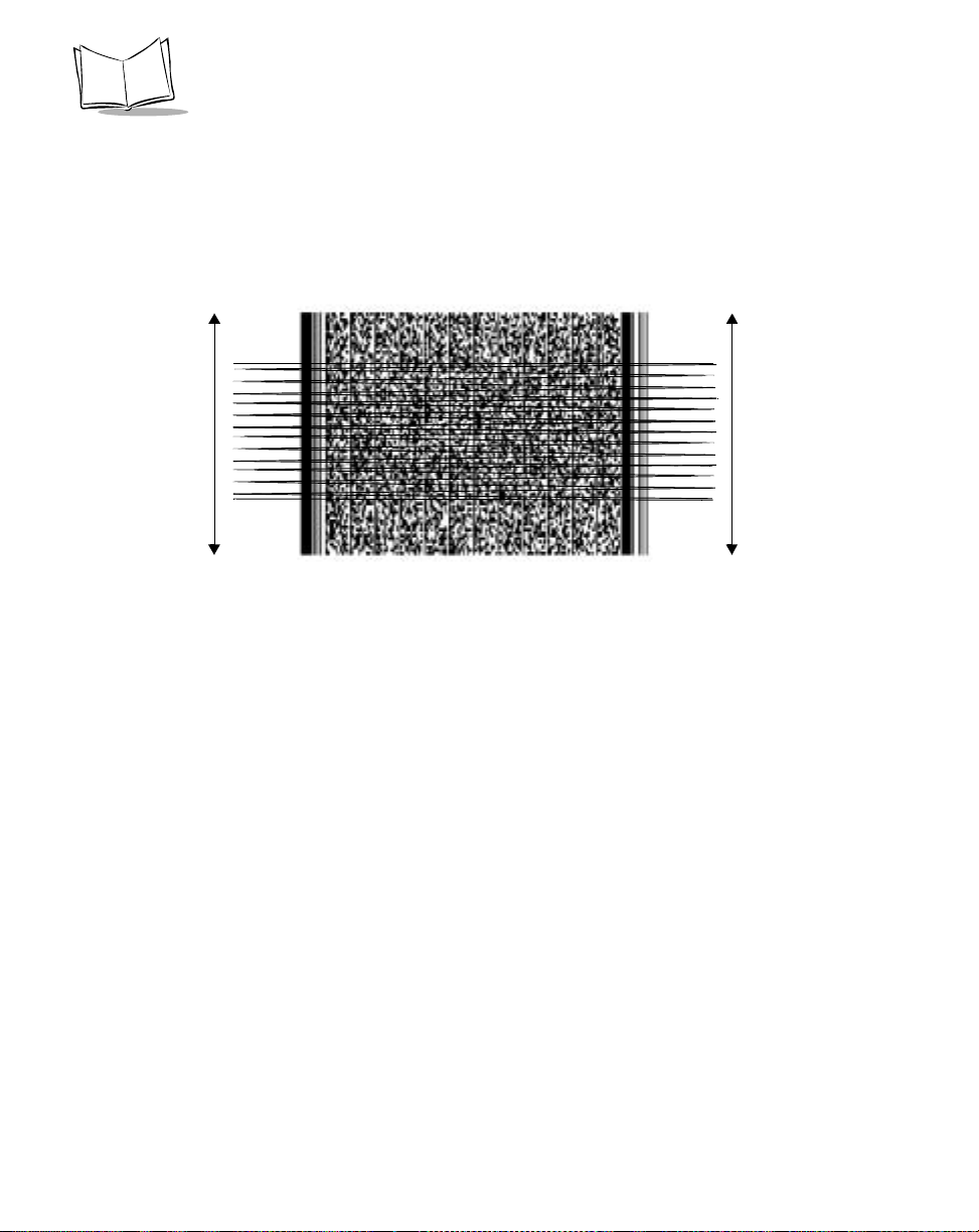
Smart Raster
In Smart Raster mode, a single scan line pattern appears. If the bar code is a standard bar
code, the scanner decodes the symbol. If the bar code is a 2-D bar code, the scanning
patterns open up to a full, optimized Raster pattern as soon as the scanner is properly
aligned over the bar code.
Single Scan Line Pattern
Open Raster Pattern
Y-Axis
Horizontal Displacement (X - Axis)
Figure 1-5. Smart Raster Scanning Pattern
When using the Raster pattern, the pattern must cover the top and bottom of the 2D symbol.
If it does not completely cover the bar code pull the bar code further away until the pattern
completely covers the bar code. Make sure the scan pattern extends at least three quarters
of an inch beyond the edges of the bar code.
3/4”
3/4”
Figure 1-6. Raster Pattern Expanded Over PDF417 Bar Code
1-11
MK2000 MicroKiosk Product Reference Guide
If the vertical scan pattern is not high enough to cover a “tall” PDF417 symbol, move the
bar code slowly down toward the bottom of the scan beam, keeping the beam horizontal to
the rows and then slowly back upward to the top. Alternatively, move the bar code further
away from the scanner until the scan pattern covers a larger portion of the bar code in the
vertical direction.
Figure 1-7. Moving Scan Pattern Upward and Downward on “Tall” PDF417 Bar Code
The scan beam does not have to be perfectly parallel with the top and bottom of the symbol
(up to a 4
o
tilt is permitted).
Ensure the symbol is in good condition.
1-12

MK2000 Introduction
Scanning Composite (2D) Bar Codes
A composite bar code is a combination of a standard bar code (RSS, UPC/EAN or UPC/ EAN-128) and a 2-D bar code (CC-A, CC-B or CC-C).
When scanning a composite bar code:
• Keep the scan pattern parallel to the 2D symbol’s rows.
• Hold the bar coded item at an angle which does not cause specular reflection (see
Specular Reflection on page 1-14).
• Hold the bar code close for small bar codes and farther away for large bar codes.
• When using the single scan line pattern, aim the scan line at the middle of the 2-D
portion. The scan pattern will open up to an optimized Raster pattern and decode
both the 2-D and standard bar code portion of the composite code.
Aim the single scan line at the center of
the 2D portion
Figure 1-8. Composite Scanning
Raster pattern will expand to decode
both portions
1-13

MK2000 MicroKiosk Product Reference Guide
Specular Reflection
When laser beams reflect directly back into the scanner from the bar code, they can “blind” the scanner and make decoding difficult. This phenomenon is called specular reflection.
To avoid this, scan the bar code so that the beam does not bounce directly back. But don’t
scan at too oblique an angle; the scanner needs to collect scattered reflections from the
scan to make a su cce ss ful d ecod e. P ra ct ice qu ic kl y sho w s what t ole ra nc es to w ork w i thi n.
Side Views
Specular reflection.
Reflected beam is
within specular dead
zone and prevents
decode.
e
d
o
C
r
a
B
Tilt Bar Code At Slight Angle (Up to 30°)
°
0
3
d
o
C
r
a
B
No specular
reflection.
Decode can occur.
e
Figure 1-9. Avoiding Specular Reflection
When scanning a 1D bar code, there is only a small specular dead zone to avoid (+
the direct laser beam). The specular dead zone is larger for scanning PDF417 (+
2o from
9o from
the direct laser beam). However, the scanner is not effective if its beams hit the bar code’s
surface at an angle greater than 30
o
from the normal to that surface.
1-14
 Loading...