

Page 1
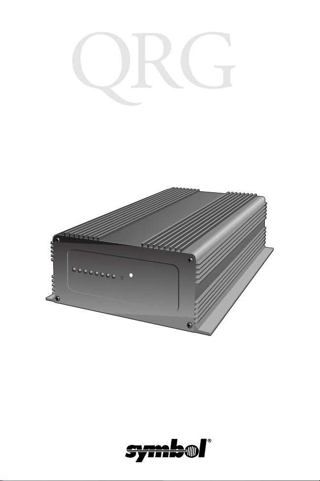
MG+ 486
Page 2

MG+ 486
2000 SYMBOL TECHNOLOGIES, INC. All rights reserved.
Symbol reserves the right to make changes to any product to improve reliability,
function, or design.
Symbol does not assume any product liability arising out of, or in connection with, the
application or use of any product, circuit, or application described herein.
No license is granted, either expressly or by implication, estoppel, or otherwise under
any patent right or patent, covering or relating to any combination, system, apparatus,
machine, material, method, or process in which Symbol products might be used. An
implied license only exists for equipment, circuits, and subsystems contained in Symbol
products.
Symbol and the Symbol logo are registered trademarks of Symbol Technologies, Inc.
Other product names mentioned in this manual may be trademarks or registered
trademarks of their respective companies and are hereby acknowledged.
Symbol Technologies, Inc.
One Symbol Plaza
Holtsville, N.Y. 11742-1300
http://www.symbol.com
Patents
This product is covered by one or more of the following U.S. and foreign Patents:
U.S. Patent No.4,360,798; 4,369,361; 4,387,297; 4,460,120; 4,496,831; 4,593,186;
4,603,262; 4,607,156; 4,652,750; 4,673,805; 4,736,095; 4,758,717; 4,816,660;
4,845,350; 4,896,026; 4,897,532; 4,923,281; 4,933,538; 4,992,717; 5,015,833;
5,017,765; 5,021,641; 5,029,183; 5,047,617; 5,103,461; 5,113,445; 5,130,520;
5,140,144; 5,142,550; 5,149,950; 5,157,687; 5,168,148; 5,168,149; 5,180,904;
5,216,232; 5,229,591; 5,230,088; 5,235,167; 5,243,655; 5,247,162; 5,250,791;
5,250,792; 5,260,553; 5,262,627; 5,262,628; 5,266,787; 5,278,398; 5,280,162;
5,280,163; 5,280,164; 5,280,498; 5,304,786; 5,304,788; 5,306,900; 5,321,246;
5,324,924; 5,337,361; 5,367,151; 5,373,148; 5,378,882; 5,396,053; 5,396,055;
5,399,846; 5,408,081; 5,410,139; 5,410,140; 5,412,198; 5,418,812; 5,420,411;
5,436,440; 5,444,231; 5,449,891; 5,449,893; 5,468,949; 5,471,042; 5,478,998;
5,479,000; 5,479,002; 5,479,441; 5,504,322; 5,519,577; 5,528,621; 5,532,469;
5,543,610; 5,545,889; 5,552,592; 5,557,093; 5,578,810; 5,581,070; 5,589,679;
5,589,680; 5,608,202; 5,612,531; 5,619,028; 5,627,359; 5,637,852;5,664,229;
5,668,803; 5,675,139; 5,693,929; 5,698,835; 5,705,800; 5,714,746; 5,723,851;
5,734,152; 5,734,153; 5,742,043; 5,745,794; 5,754,587; 5,762,516; 5,763,863;
5,767,500; 5,789,728; 5,789,731; 5,808,287; 5,811,785; 5,811,787; 5,815,811;
5,821,519; 5,821,520; 5,823,812; 5,828,050; 5,850,078; 5,861,615; 5,874,720;
5,875,415; 5,900,617; 5,902,989; 5,907,146; 5,912,450; 5,914,478; 5,917,173;
5,920,059; 5,923,025; 5,929,420; 5,945,658; 5,945,659; 5,946,194; 5,959,285;
D305,885; D341,584; D344,501; D359,483; D362,453; D363,700; D363,918;
D370,478; D383,124; D391,250; D405,077; D406,581; D414,171; D414,172.
Invention No. 55,358; 62,539; 69,060; 69,187 (Taiwan); No. 1,601,796; 1,907,875;
1,955,269 (Japan).
European Patent 367,299; 414,281; 367,300; 367,298; UK 2,072,832; France 81/
03938; Italy 1,138,713.
rev. 11/99
Page 3
Quick Reference
Introduction
The Mobile Gateway Plus 486 (MG+ 486) is a small, rugged
computer used as a platform for in-vehicle communications and
connectivity by Symbol portable data terminals. It provides wireless
network communications and RS-232 flexibility.
The MG+ 486 supports MS-DOS, GS-DOS and Pharlap RTOS
operating environments using industry standard protocols. It is
available with an 80486 processor.
Input/Output Ports
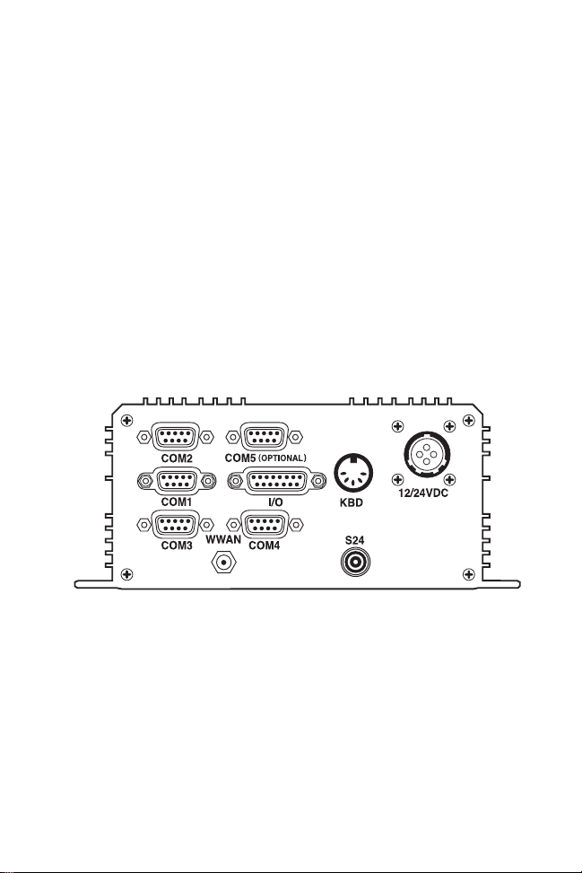
The MG+ 486 has up to 5 external serial ports and one I/O port on
the rear panel of the unit.
COM1
This RS-232 DTE serial port uses a 9-pin male DSUB connector.
The COM1 port can be used to interface with devices such as
portable terminals and laptop PCs, and connects to an RS-232 port
on a host computer using a null modem cable. COM1 also can be
connected to a host console adapter that boots the MG+ 486 into a
mode which redirects the video and keyboard data to COM1, so an
external PC running Procomm or equivalent terminal software can
control the MG+ 486.
1
Page 4

MG+ 486
COM2
COM2 is an RS-232 DTE serial port using a 9-pin female DSUB
connector.
12/24VDC
This connector provides the input power for the MG+ 486. The
MG+ 486 operates from 12 or 24 V (9V to 32V) sources.
Options
Several of the following options are also available:
COM3 - Additional RS-232 DTE serial port.
COM4 - Additional RS-232 DTE serial port.
COM5 - DTE serial port that can be configured as either
RS-232, SAE J1708 or TTL level.
I/O - This Input/Output port is a 26-pin high density female
DSUB connector allowing the MG+ 486 to interface with external devices. Five digital open collector outputs/inputs are
provided on this port, and three digital inputs that wake up
the MG+ 486. The outputs can be used for external control,
while the inputs can be used for monitoring the state of external switches or other sensory devices. Three power sources
(unswitched 5V up to 2ma, switched 5V up to 0.5A, filtered/
transient protected input voltage up to 1A) and several ground
pins are also provided. Optional are two 8-bit analog-to-digital channels set up for 0 to 12.5V (voltage range can be modified). Also optional are two 16-bit frequency/pulse counter
channels.
Keyboard - Optional standard XT keyboard connection typically used for development units.
WWAN Antenna - SMA-style connector which provides an interface to external radio antenna.
2
Page 5
Quick Reference
GPS Antenna - SMB-style connector which provides an interface to an external GPS antenna.
S24 Antenna - Reverse BNC style connector which provides
an interface to external S24 radio antenna.
LED Indicators
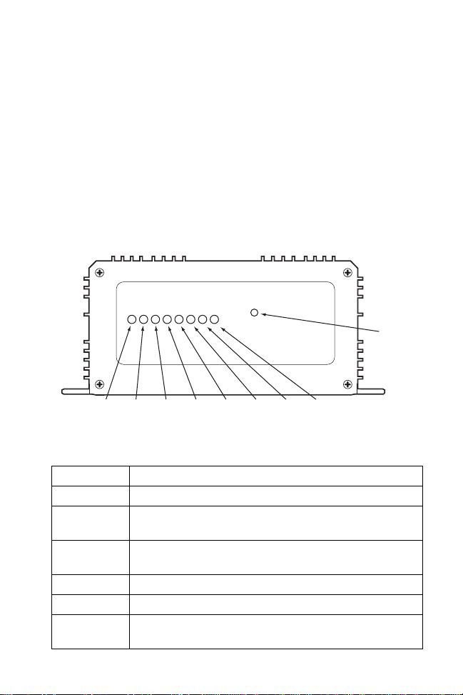
The MG+ 486 has 8 LED indicators on the front panel providing
status to the user.
RESET
ON TXD2 RXD2 TXD3 RXD3 USER USER FAULT
The LEDs (left to right) are described below:
LED Description
ON Power is applied to the CPU of the MG+ 486.
TXD2 The CPU is transmitting information to COM2 (can be
RXD2 The CPU is receiving information from COM2 (can be
TXD3 The CPU is transmitting information to COM3.
RXD3 The CPU is receiving information from COM3.
USER Application-specific, can be programmed by the user (can
factory set for COM4).
factory set for COM4).
be used for S24 activity).
3
Page 6

MG+ 486
LED Description
USER Application-specific, can be programmed by the user.
FAULT LED stays on if MG+ 486 does not boot properly. Can be
programmed by the user.
Reset Switch
This is a momentary switch located on the front panel, to the right
of the LEDs. To ensure a clean reset, hold the button down for more
than one second, then release.
Internal Interfaces
Radio Interface
The MG+ 486 can be factory configured for one of the following
radios:
• Ericsson M3090 WAN radio
• RIM 902 WAN radio.
Note: Other radio configurations will be available in the fu-
ture.
The radio is connected to the COM3 port. The optional external
COM3 connector will point to the external connector only when
the radio is not selected.
GPS Interface
The MG+ 486 can be factory configured for a Rockwell Jupiter GPS
receiver. The GPS receiver is connected to the COM4 port. Jumper
headers JP8 and JP9 are used to configure the GPS. The optional
external COM4 connector is connected to the COM4 port only
when the GPS is not selected.
The GPS is backed up by the onboard 3.3V (as long as the main
power is available, or the internal backup NiCd battery is charged).
4
Page 7

Quick Reference
PC104 Interface
The MG+ 486 accommodates one PC104 16/8 bit card.
PCMCIA Interface
The MG+ 486 accommodates up to two 5V PCMCIA cards (if both
slots are used, a type 3 card may be installed in the top slot only).
The interface supports hot plug-in.
Backup Battery
The MG+ 486 accommodates an 8.4V 500ma NiCd backup battery
(J2). The backup battery provides power during brownout periods
and backs up the RTCs when main power is not available. The
battery is not user-serviceable.
Installing the MG+ 486
Caution: Improper installation can cause damage to both the ve-
hicle and the MG+ 486. Installation should be performed by an experienced technician.
To install the MG+ 486:
1. Select a mounting location that is flat and provides adequate
support and ventilation for the MG+ 486.
Note: The MG+ 486 chassis must be grounded to the vehicle
chassis.
2. Secure the MG+ 486 with appropriate nuts and bolts. Selflocking nuts or lock washers must be used.
3. Connect the power cable.
4. Route the power cable to the battery power source.
5. Connect the V+ wire to the battery power source, splicing a
fuseholder with a 10 amp fuse in-line with the power source.
5
Page 8
MG+ 486
Note: Locate the fuse as close as possible to the battery power
source.
6. Connect the Vehicle Accessory Power to the vehicle accessory
bus, splicing a fuseholder with a 1 amp fuse in-line with the
accessory power source.
Note: Locate the fuse as close as possible to the accessory pow-
er source.
The accessory bus is the ‘switched’ power source controlled by
the ignition key. Connect the power cable to the power source
using appropriate connectors.
7. Place a CAUTION label on each fuseholder.
8. Plug the circular connector into the +12/24 VDC connector on
the MG+ 486.
Voltage & Current Requirements
Input Voltage
V+ Input Current
Accessory Power Input Current
6
+12/24 VDC
4.5 A Max
10 mA
Page 9

Quick Reference
Service Information
Before you use the unit, it must be configured to operate in your facility’s network and
run your applications.
If you have a problem running your unit or using your equipment, contact your
facility’s Technical or Systems Support. If there is a problem with the equipment, they
will contact the Symbol Support Center:
United States 1-800-653-5350 Canada 905-629-7226
United Kingdom 0800 328 2424 Asia/Pacific 337-6588
Australia 1-800-672-906 Austria 1-505-5794
Denmark 7020-1718 Finland 9 5407 580
France 01-40-96-52-21 Germany 6074-49020
Italy 2-484441 Mexico 5-520-1835
Netherlands 315-271700 Norway 66810600
South Africa 11-4405668 Spain 9-1-320-39-09
Sweden 84452900
Latin America Sales Support 1-800-347-0178 Inside US
+1-561-483-1275 Outside US
Europe/Mid-East Distributor Operations
Contact local distributor or call
+44 118 945 7360
Warranty
Symbol Technologies, Inc. (“Symbol”) manufactures its hardware products in
accordance with industry-standard practices. Symbol warrants that for a period of
twelve (12) months from date of shipment, products will be free from defects in
materials and workmanship.
This warranty is provided to the origin al owner only and is not transferable to any third
party. It shall not apply to any product (i) which has been repaired or altered unless
done or approved by Symbol, (ii) which has not been maintained in accordance with
any operating or handling instructions supplied by Symbol, (iii) which has been
subjected to unusual physical or electrical stress, misuse, abuse, power shortage,
negligence or accident or (iv) which has been used other than in accordance with the
product operating and handling instructions. Preventive maintenance is the
responsibility of customer and is not covered under this warranty.
Wear items and accessories having a Symbol serial number, will carry a 90-day limited
warranty. Non-serialized items will carry a 30-day limited warranty.
7
Page 10

MG+ 486
Warranty Coverage and Procedure
During the warranty period, Symbol will repair or replace defective products returned
to Symbol’s manufacturing plant in the US. For warranty service in North America, call
the Symbol Support Center at 1-800-653-5350. International customers should contact
the local Symbol office or support center. If warranty service is required, Symbol will
issue a Return Material Authorization Number. Products must be shipped in the
original or comparable packaging, shipping and insurance charges prepaid. Symbol
will ship the repaired or replacement product freight and insurance prepaid in North
America. Shipments from the US or other locations will be made F.O.B. Symbol’s
manufacturing plant.
Symbol will use new or refurbished parts at its discretion and will own all parts
removed from repaired products. Customer will pay for the replacement product in
case it does not return the replaced product to Symbol within 3 days of receipt of the
replacement product. The process for return and customer’s charges will be in
accordance with Symbol’s Exchange Policy in effect at the time of the exchange.
Customer accepts full responsibility for its software and data including the appropriate
backup thereof.
Repair or replacement of a product during warranty will not extend the original
warranty term.
Symbol’s Cust omer Service organization offers an array of service plans, such as on-site,
depot, or phone support, that can be implemented to meet customer’s special
operational requirements and are available at a substantial discount during warranty
period.
General
Except for the warranties stated above, Symbol disclaims all warranties, express or
implied, on products furnished hereunder, including without limitation implied
warranties of merchantability and fitness for a particular purpose. The stated express
warranties are in lieu of all obligations or liabilities on part of Symbol for damages,
including without limitation, special, indirect, or consequential damages arising out of
or in connection with the use or performance of the product.
Seller’s liability for damages to buyer or others resulting from the use of any product,
shall in no way exceed the purchase price of said product, except in instances of injury
to persons or property.
Some states (or jurisdictions) do not allow the exclusion or limitation of incidental or
consequential damage s, so the proceed ing exclusion or limitation may not appl y to you.
8
Page 11

Quick Reference
Regulatory Information
Radio Frequency Interference Requirements
This device has been tested and found to comply with the limits for a Class B digital
device pursuant to Part 15 of the Federal Communications Commissions Rules and
Regulation. These limits are designed to provide reasonable protection against harmful
interference when the equipment is operated in a commercial environment. This
equipment generates, uses, and can radiate radio frequency energy and, if not installed
and used in accordance with the instruction manual, may cause harmful interference to
radio communications. Operation of this equipment in a residential area is likely to
cause harmful interference in which case the user will be required to correct the
interference at his own expense.
However, there is no guarantee that interference will not occur in a particular
installation. If the equipment does cause harmful interference to radio or television
reception, which can be determined by turning the equipment off and on, the user is
encouraged to try to correct the interference by one or more of the following measures:
• Re-orient or relocate the receiving antenna.
• Increase the separation between the equipment and receiver.
• Connect the equipment into an outlet on a circuit different from that which the
receiver is connected.
• Consult the dealer or an experienced radio/TV technician for help.
This device complies with FCC Part 15. Operation is subject to the following two
conditions: (1) this device may not cause harmful interference and (2) this device must
accept any interference received, including interference that may cause undesired
operation.
Radio Frequency Interference Requirements - Canada
This device complies with RSS 210 of Industry & Science Canada. Operation is subject
to the following two conditions: (1) this device may not cause harmful interference and
(2) this device must accept any interference received, including interference that may
cause undesired operation.
This Class B digital apparatus complies with Industry Canada Standard ICES-003.
Cet appareil numérique de la classe B est conform à la norme NMB-003 d’Industrie
Canada.
CE Marking and European Union Compliance
Products intended for sale within the European Union are marked with the
CE Mark which indicates compliance to applicable Directives and
European Normes (EN), as follows. Amendments to these Directives or
ENs are included:
9
Page 12

Applicable Directives
• Electromagnetic Compatibility Directive 89/336/EEC
• Low Voltage Directive 73/23/EEC
Applicable Standards
• EN 55022:1998, Limits and Methods of Measurement of Radio Disturbance
Characteristics of Information Technology Equipment
• EN 55024:1998; Information Technology equipment - Immunity characteristics Limits and methods of measurement
• IEC 1000-4-2:1995; Electromagnetic compatibility (EMC); Part 4:Testing and
measurement techniques; Section 4.2:Electrostatic discharge immunity test
• IEC 1000-4-3:1997; Electromagnetic Compatibility (EMC); Part 4:Testing and
measurement techniques; Section 3. Radiated, radio frequency, electromagnetic
field immunity test.
• IEC 1000-4-4:1995; Electromagnetic compatibility (EMC); Part 4: Testing and
measurement techniques; Section 4:Testing electrical fast transient,/Burst immunity.
• IEC1000-4-5:1995; Electromagnetic compatibility (EMC), Part 4: Testing and
measurement techniques; Section 5: Surge Immunity
• IEC 1000-4-6:1996; Electromagnetic compatibility (EMC), Part 4:Testing and
measurement techniques; Section 6: Immunity to conducted disturbances,
induced by radio frequency fields.
• IEC 1000-4-11:1994; Electromagnetic compatibility (EMC), Part 4: Testing and
measurement techniques; Section 11: Voltage Dips, Short Interruptions, and Voltage Variations.
• EN 60 950 + A1+A2+A3+A4+A11 - Safety of Information Technology Equipment Including Electrical Business Equipment
• EN 60 825-1 (EN 60 825) - Safety of Devices Containing Lasers
72-40689-01
Revision A — January 2000
Symbol Technologies, Inc. One Symbol Plaza Holtsville, NY 11742-1300
 Loading...