

Page 1
SERVICE MANUAL
Page 2

SYM FORWARD
This service manual contains the technical data of each component
inspection and repair for the SYM series motorcycle. The manual is shown
with illustrations and focused on 「Service Procedures」, 「Operation Key
Points」, and 「Inspection Adjustment」 so that provides technician with service
guidelines.
If the style and construction of the motorcycle are different from that of the
photos, pictures shown in this manual, the actual vehicle shall prevail.
Specifications are subject to change without notice.
This manual that contains all data, illustration, indication and specifications
is based on current production information. SYM reserves the right to make
changes at any time without notice and without incurring any obligation
whatever. No part of this manual can be duplicated by any means without
written permission of SANYANG.
SERVICE DEPARTMENT
SAN YANG INDUSTRY CO., LTD.
Page 3
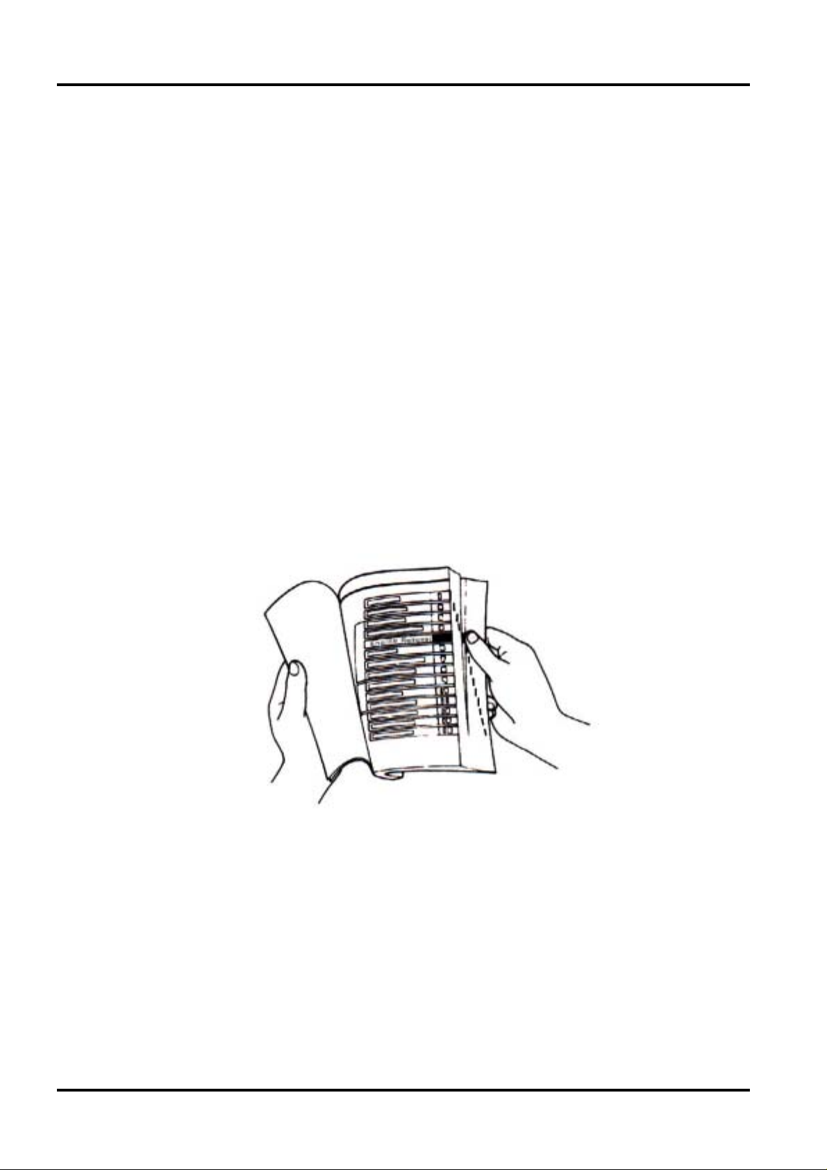
HOW TO USE THIS MANUAL SYM
This service manual describes basic information of different system parts and
system inspection & service for SYM series motorcycles. In addition, please
refer to the manual contents in detailed for the model you serviced in
inspection and adjustment.
The first chapter covers general information and trouble diagnosis.
The second chapter covers service maintenance.
The third to the eleventh chapters cover engine and driving systems.
The twelfth to fifteenth chapters are contained the parts set of assembly
body.
The sixteenth chapter is electrical equipment.
The seventh chapter is for wiring diagram.
Please see index of content for quick having the special parts and system
information.
Page 4

SYM CONTENTS
CONTENTS
GENERAL INFORMATION/TROUBLE DIAGNOSIS...................................1
MAINTENANCE INFORMATION .................................................................2
LUBRICATION SYSTEM..............................................................................3
FUEL SYSTEM.............................................................................................4
ENGINE REMOVAL......................................................................................5
CYLINDER HEAD/VALVE............................................................................6
CYLINDER/PISTON......................................................................................7
"V" TYPE BELT DRIVING SYSTEM/KICK STARTER ARM .......................8
FINAL DRIVING MECHANISM.....................................................................9
A.C. GENERATOR/STARTING CLUTCH....................................................10
CRANKCASE/CRANKSHAFT .....................................................................11
BODY COVER..............................................................................................12
BRAKE SYSTEM..........................................................................................13
STEERING/FRONT WHEEL/FRONT SHOCK ABSORBER........................14
REAR WHEEL/SUSPENSION......................................................................15
ELECTRICAL EQUIPMENT.........................................................................16
ELECTRICAL DIAGRAM .............................................................................17
Page 5
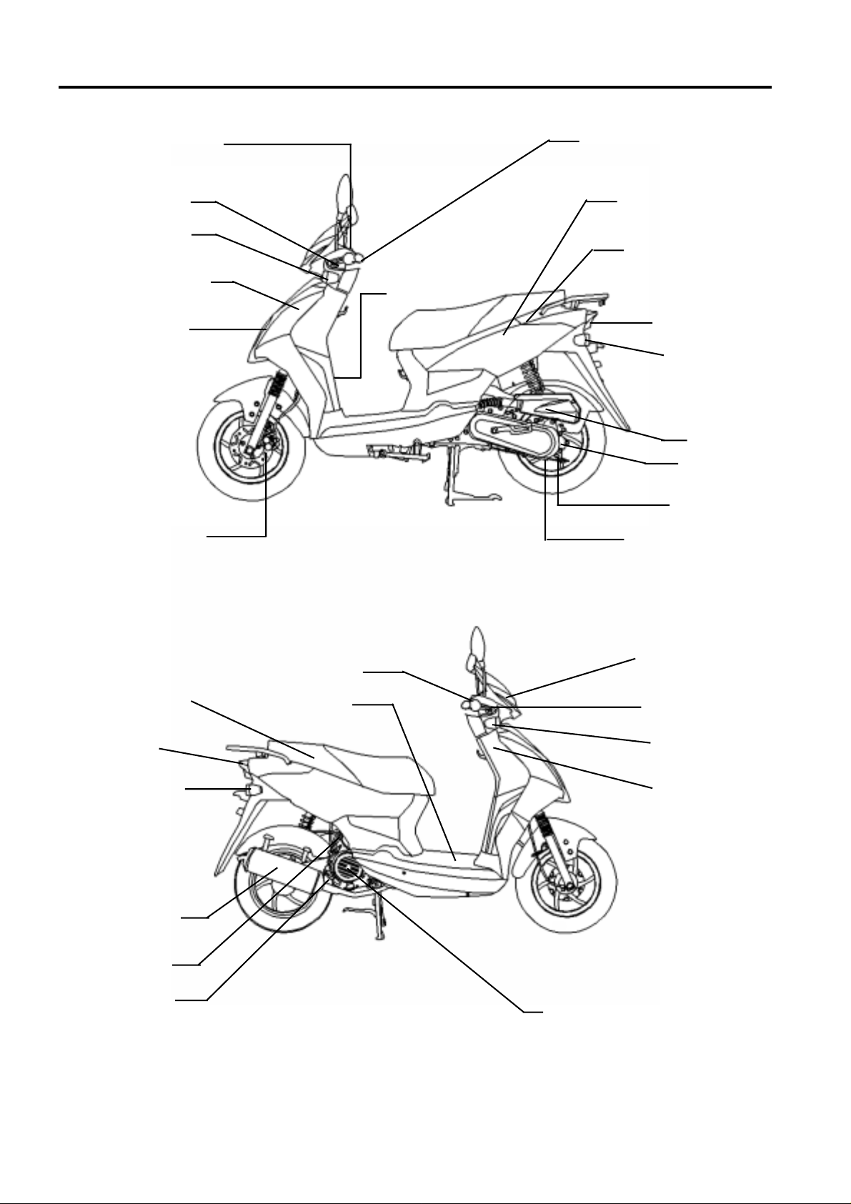
MECHANISM ILLUSTRATIONS SYM
r
r
r
r
brake lever
Rea
Front turn
signal light
Horn/REG.REC
Head light/
Position light
Front disk brake
Meter
Frame numbe
High&Low beam/Seat
open/turn signal/horn
Start magnetic switch
Fuel tank / Fuel unit
Tail light
RR. turning
signal light
Ai
cleane
Gearoil filling
bolt
Gear oil draining
bolt
Engine number/engine
oil draining bolt
Engine control
switch
Tail light
Rear turn
signal light
Exhaust muffler
Ignition coil
Oil level
Light/starter switch
Battery/Fuse/CDI
Winker relay
Front brake lever
Front turn
signal light
Ignition switch
A.C. Generator
Page 6
SYM 1. GENERAL INFORMATION/TROUBLE DIAGNOSIS
SYMBOLS AND MARKS....................1-1
GENERAL SAFETY............................1-2
SERVICE PRECAUTIONS.................1-3
SPECIFICATIONS..............................1-9
TORQUE VALUES (ENGINE)..............1-10
TORQUE VALUES (FRAME)...............1-11
TROUBLES DIAGNOSIS..................... 1-12
LUBRICATION POINTS....................... 1-16
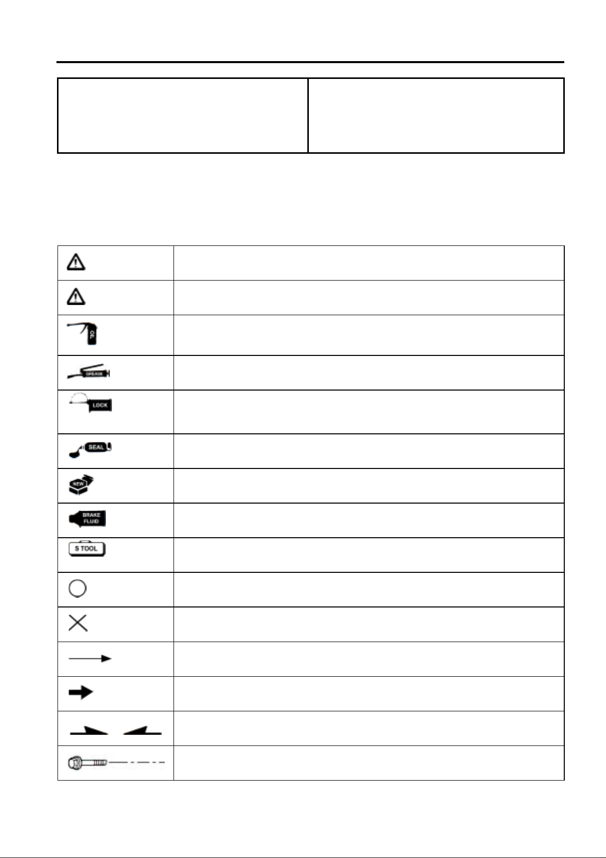
SYMBOLS AND MARKS
Symbols and marks are used in this manual to indicate what and where the special service are
needed, in case supplemental information is procedures needed for these symbols and marks,
explanations will be added to the text instead of using the symbols or marks.
Warning
Caution
Engine oil
Grease
Means that serious injury or even death may result if procedures are not
followed.
Means that equipment damages may result if procedures are not followed.
Limits to use SAE 10W-30 API SH/CD class oil. Warranty will not cover the
damage that caused by not apply with the limited engine oil.
King Mate G-3 is recommended.
Locking sealant
Oil seal
Renew
Brake fluid
Special tools
Correct
Wrong
Indication
Directions
Apply sealant, medium strength sealant should be used unless otherwise
specified.
Apply with lubricant.
Replace with a new part before installation.
Use recommended brake fluid DOT3 or WELLRUN brake fluid.
Special service tools.
Meaning correct installation.
Meaning wrong installation.
Indication of components.
Indicates position and operation directions.
Components assembly directions each other.
Indicates where the bolt installation direction, --- means that bolt cross
through the component (invisibility).
1-1
Page 7
1. GENERAL INFORMATION/TROUBLE DIAGNOSIS SYM
GENERAL SAFETY
Carbon monoxide
If you must run your engine, ensure the place is
well ventilated. Never run your engine in a
closed area. Run your engine in an open area, if
you have to run your engine in a closed area, be
sure to use an extractor.
Caution
Exhaust contains toxic gas which may cause
one to lose consciousness and even result in
death.
Gasoline
Gasoline is a low ignition point and explosive
material. Work in a well-ventilated place, no
flame or spark should be allowed in the work
place or where gasoline is being stored.
Caution
Gasoline is highly flammable, and may explode
under some conditions, keep it away from
children.
Used engine oil
Caution
Prolonged contact with used engine oil (or
transmission oil) may cause skin cancer
although it might not be verdict.
Hot components
Battery
Caution
Battery emits explosive gases; flame is
strictly prohibited. Keep the place well
ventilated when charging the battery.
Battery contains sulfuric acid (electrolyte)
which can cause serious burns so be careful
do not be spray on your eyes or skin. If you
get battery acid on your skin, flush it off
immediately with water. If you get battery
acid in your eyes, flush it off immediately
with water, then go to hospital to see an
ophthalmologist.
If you swallow it by mistake, drink a lot of
water or milk, and take some laxative such
as castor oil or vegetable oil, and then go to
see a doctor.
Keep electrolyte beyond reach of children.
Brake shoe
Do not use an compressed air or a dry brush to
clean components of the brake system, use a
vacuum cleaner or the equivalent to avoid
asbestos dust flying.
Caution
Inhaling asbestos dust may cause disorders
and cancer of the breathing system.
Caution
Components of the engine and exhaust system
can become extremely hot after engine running.
They remain very hot even after the engine has
been stopped for some time. When performing
service work on these parts, wear insulated
gloves and wait until cooling off.
1-2
Brake fluid
Caution
Spilling brake fluid on painted, plastic, or rubber
parts may cause damage to the parts. Place a
clean towel on the above-mentioned parts for
protection when servicing the brake system.
Keep brake fluid beyond reach of children.
Page 8
SYM 1. GENERAL INFORMATION/TROUBLE DIAGNOSIS
SERVICE PRECAUTIONS
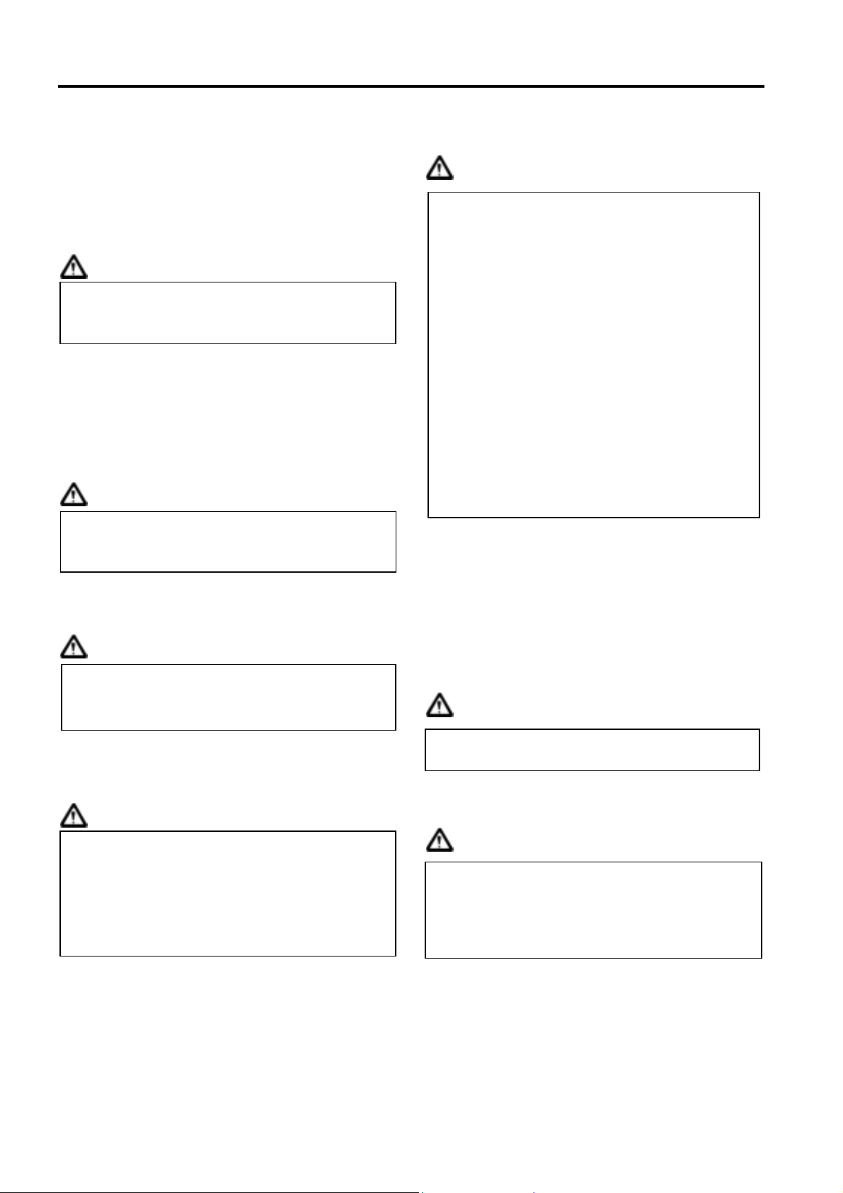
Always use with SANYANG genuine parts
and recommended oils. Using non-designed
parts for SANYANG motorcycle may damage
the motorcycle.
Never bend or twist a control cable to prevent
stiff control and premature worn out.
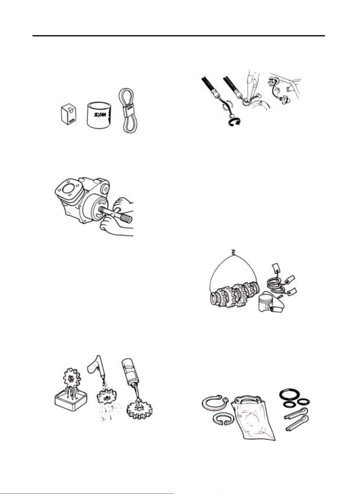
Special tools are designed for remove and
install of components without damaging the
parts being worked on. Using wrong tools
may result in parts damaged.
When servicing this motorcycle, use only
metric tools. Metric bolts, nuts, and screws
are not interchangeable with the English
system, using wrong tools and fasteners may
damage this vehicle.
Clean the outside of the parts or the cover
before removing it from the motorcycle.
Otherwise, dirt and deposit accumulated on
the part's surface may fall into the engine,
chassis, or brake system to cause a damage.
Wash and clean parts with high ignition point
solvent, and blow dry with compressed air.
Pay special attention to O-rings or oil seals
because most cleaning agents have an
adverse effect on them.
Rubber parts may become deteriorated when
old, and prone to be damaged by solvent and
oil. Check these parts before installation to
make sure that they are in good condition,
replace if necessary.
When loosening a component which has
different sized fasteners, operate with a
diagonal pattern and work from inside out.
Loosen the small fasteners first. If the bigger
ones are loosen first, small fasteners may
receive too much stress.
Store complex components such as
transmission parts in the proper assemble
order and tie them together with a wire for
ease of installation later.
Note the reassemble position of the important
components before disassembling them to
ensure they will be reassembled in correct
dimensions (depth, distance or position).
Components not to be reused should be
replaced when disassembled including
gaskets metal seal rings, O-rings, oil seals,
snap rings, and split pins.
1-3
Page 9
1. GENERAL INFORMATION/TROUBLE DIAGNOSIS SYM
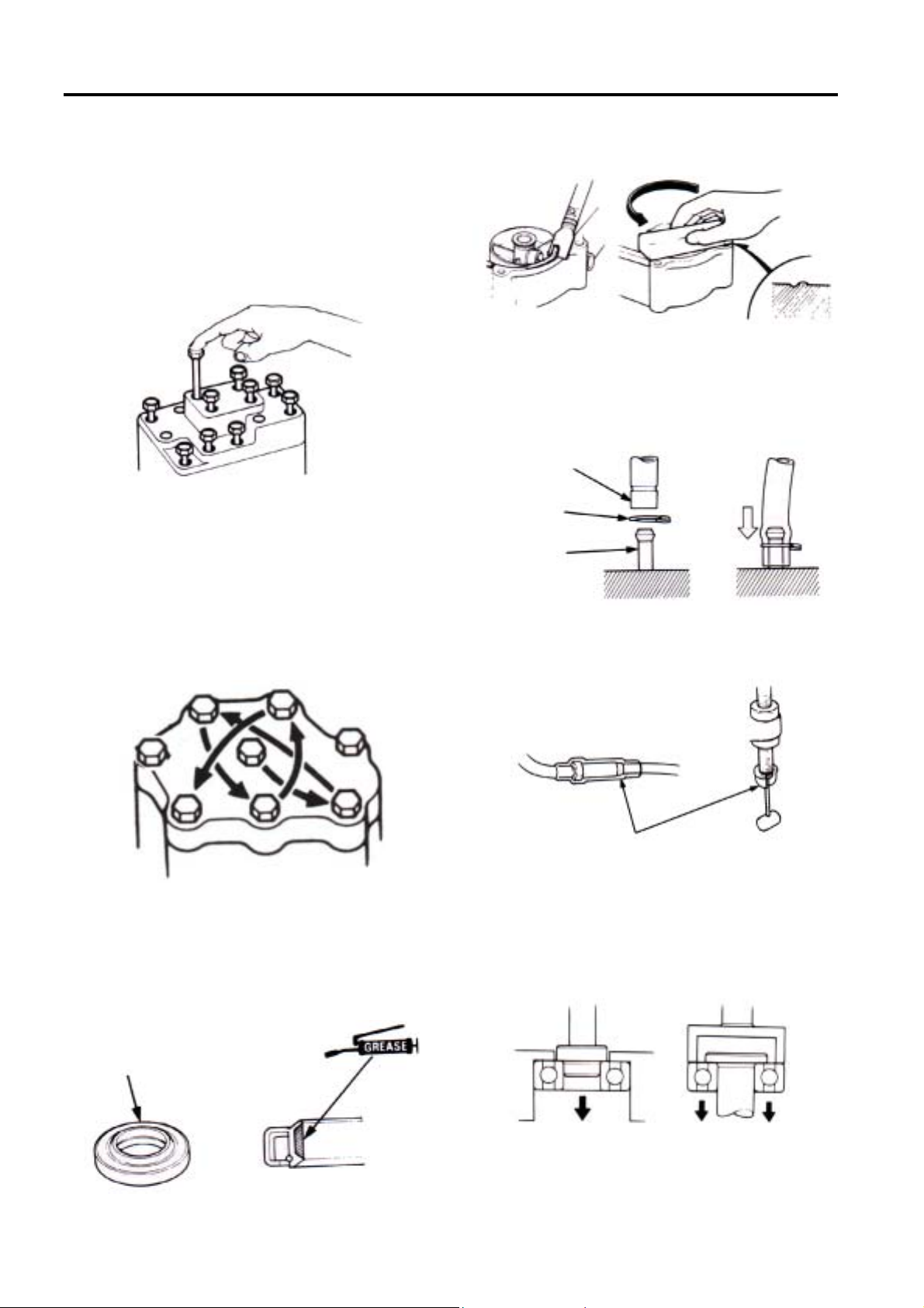
The length of bolts and screws for
assemblies, cover plates or boxes is different
from one another, be sure they are correctly
installed. In case of confusion, Insert the bolt
into the hole to compare its length with other
bolts, if its length out side the hole is the
same with other bolts, it is a correct bolt.
Bolts for the same assembly should have the
same length.
Tighten assemblies with different dimension
fasteners as follows:
Tighten all the fasteners with fingers, then
tighten the big ones with special tool first
diagonally from inside toward outside,
important components should be tightened 2
to 3 times with appropriate increments to
avoid warp unless otherwise indicated. Bolts
and fasteners should be kept clean and dry.
Do not apply oil to the threads.
When oil seal is installed, fill the groove with
grease, install the oil seal with the name of
the manufacturer facing outside, check the
shaft on which the oil seal is to be installed
for smoothness and for burrs that may
damage the oil seal.
Manufacturer's
name
Remove residues of the old gasket or sealant
before reinstallation, grind with a grindstone if
the contact surface has any damage.
The ends of rubber hoses (for fuel, vacuum,
or coolant) should be pushed as far as they
can go to their connections so that there is
enough room below the enlarged ends for
tightening the clamps.
Groove
Clamp
Connector
Rubber and plastic boots should be properly
reinstalled to the original correct positions as
designed.
The tool should be pressed against two (inner
and outer) bearing races when removing a
ball bearing. Damage may result if the tool is
pressed against only one race (either inner
race or outer race). In this case, the bearing
should be replaced. To avoid damaging the
bearing, use equal force on both races.
Boots
Both of these examples can result in bearing damage.
1-4
Page 10
SYM 1. GENERAL INFORMATION/TROUBLE DIAGNOSIS
Lubricate the rotation face with specified
lubricant on the lubrication points before
assembling.
Check if positions and operation for installed
parts is in correct and properly.
Make sure service safety each other when
conducting by two persons.
Note that do not let parts fall down
Before battery removal operation, it has to
remove the battery negative (-) cable firstly.
Notre tools like open-end wrench do not
contact with body to prevent from circuit short
and create spark.
After service completed, make sure all
connection points is secured. Battery
positive (+) cable should be connected firstly.
And the two posts of battery have to be
greased after connected the cables.
Make sure that the battery post caps are
located in properly after the battery posts had
been serviced.
If fuse burned, it has to find out the cause
and solved it. And then replace with
specified capacity fuse.
capacity
verification
1-5
Page 11
1. GENERAL INFORMATION/TROUBLE DIAGNOSIS SYM
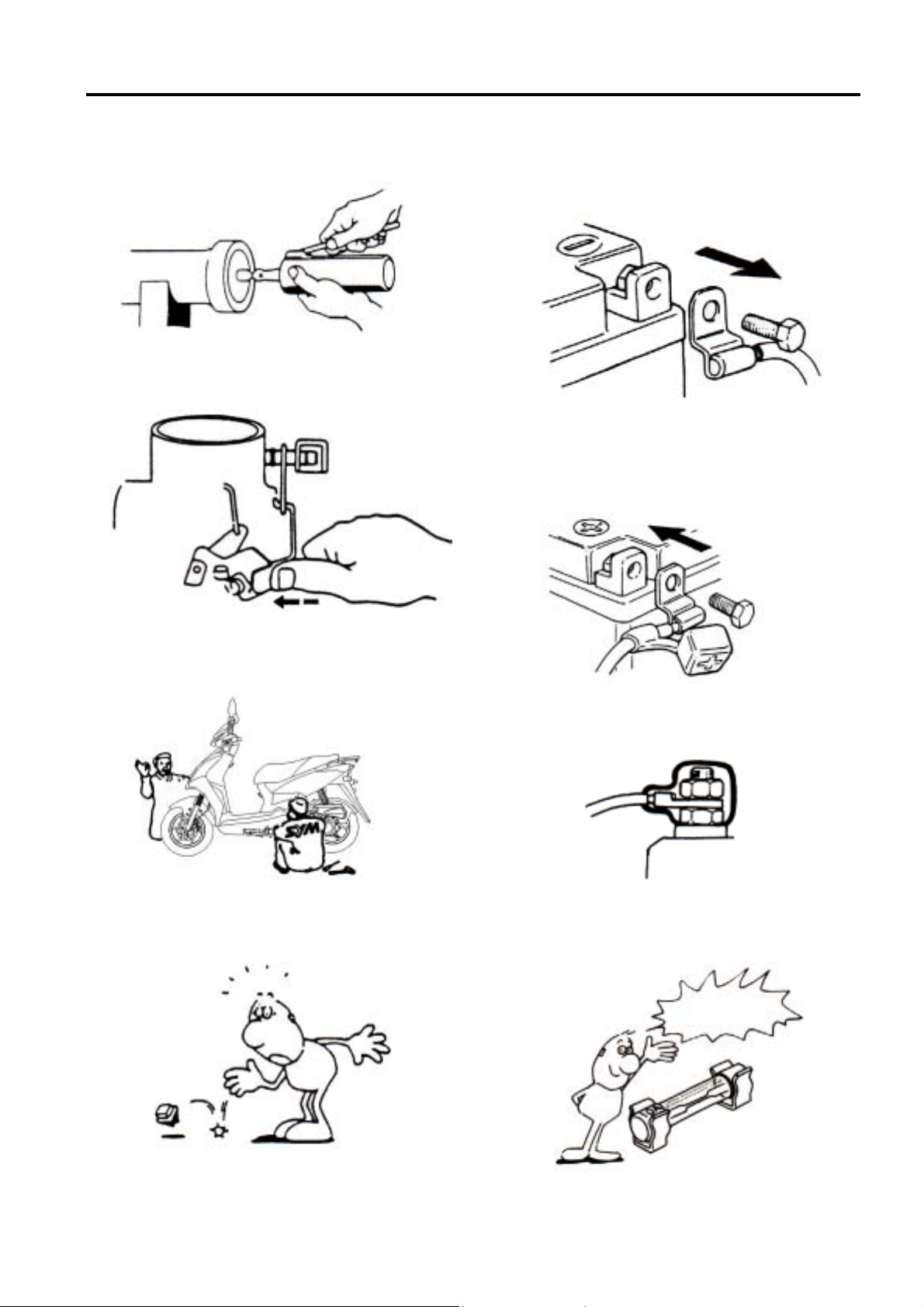
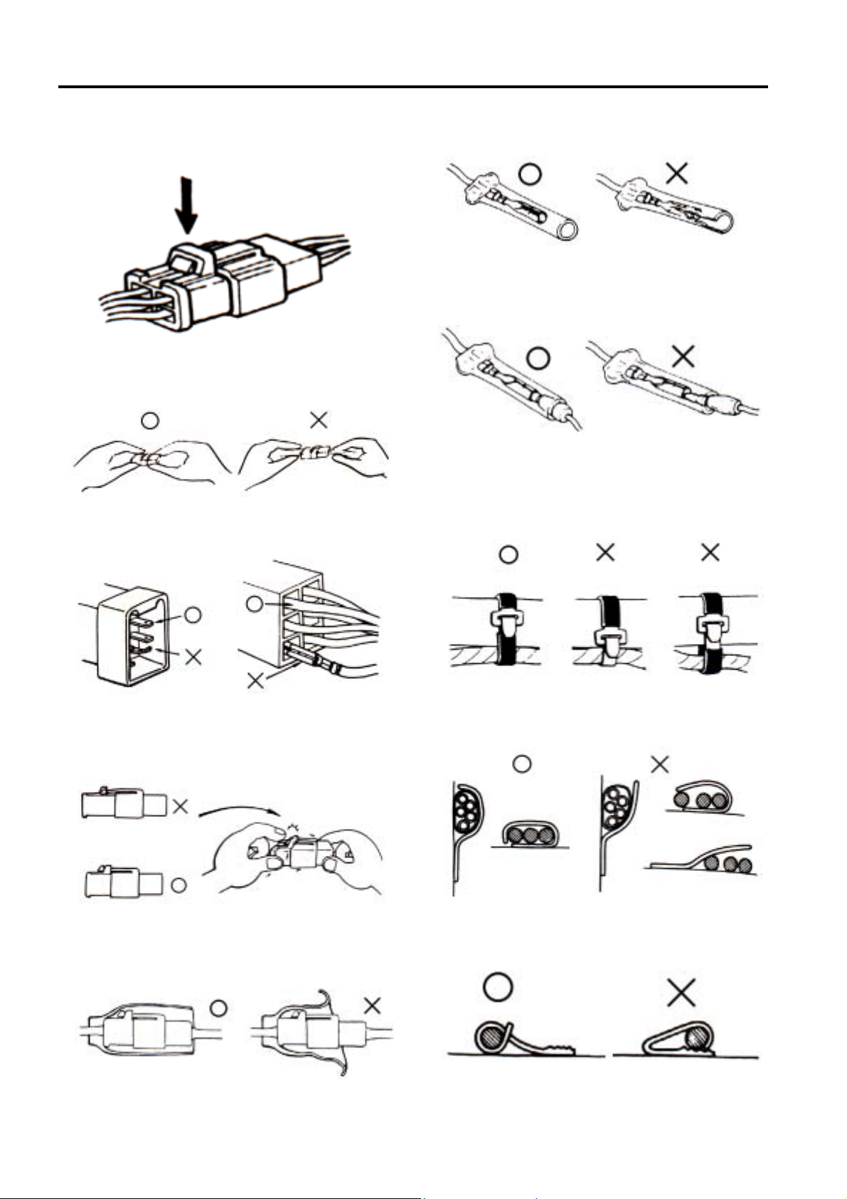
When separating a connector, it locker has to
be unlocked firstly. Then, conduct the
service operation.
Do not pull the wires as removing a
connector or wires. Hold the connector
body.
Make sure if the connector pins are bent,
extruded or loosen.
Insert the connector completely. If there are
two lockers on two connector sides, make
sure the lockers are locked in properly.
Check if any wire loose.
Check if the connector is covered by the twin
connector boot completely and secured
properly.
Before terminal connection, check if the boot
is crack or the terminal is loose.
Insert the terminal completely. Check if the
terminal is covered by the boot. Do not let
boot open facing up.
Secure wires and wire harnesses to the
frame with respective wire bands at the
designated locations. Tighten the bands so
that only the insulated surfaces contact the
wires or wire harnesses.
Wire band and wire harness have to be
clamped secured properly.
Do not squeeze wires against the weld or its
clamp.
1-6
Page 12
SYM 1. GENERAL INFORMATION/TROUBLE DIAGNOSIS
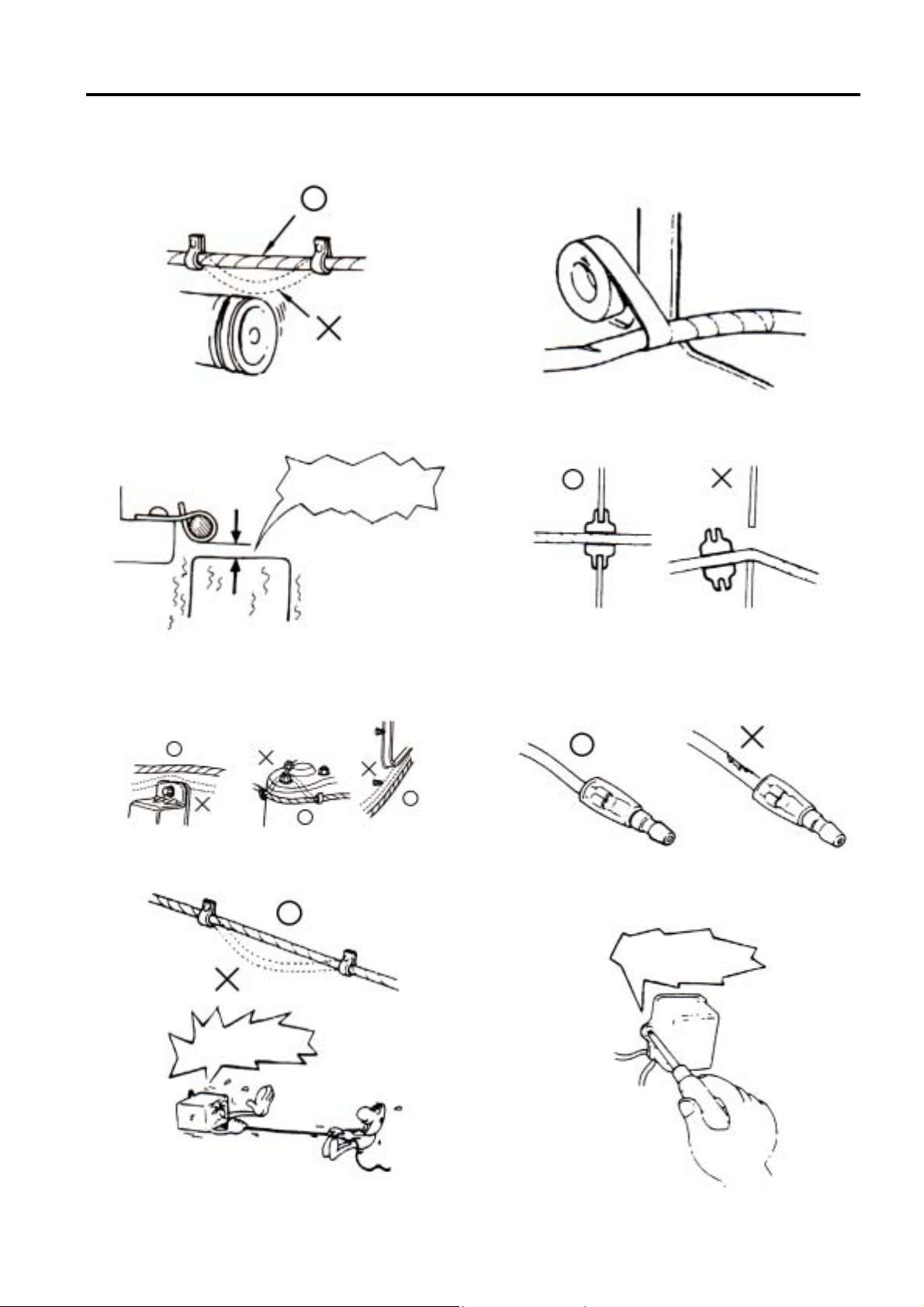
Do not let the wire harness contact with
rotating, moving or vibrating components as
routing the harness.
Keep wire harnesses far away from the hot
parts.
Route wire harness to avoid sharp edges or
corners and also avoid the projected ends of
bolts and screws.
Route harnesses so that they neither pull too
tight nor have excessive slack.
Do not extend
it too much.
Do not touch it.
Protect wires or wire harnesses with electrical
tape or tube if they contact a sharp edge or
corner. Thoroughly clean the surface where
tape is to be applied.
Secure the rubber boot firmly as applying it
on wire harness.
Never use wires or harnesses which
insulation has been broken. Wrap electrical
tape around the damaged parts or replace
them.
Never clamp or squeeze the wire harness as
installing other components.
Please do not clip or
squeeze the wire.
1-7
Page 13
1. GENERAL INFORMATION/TROUBLE DIAGNOSIS SYM
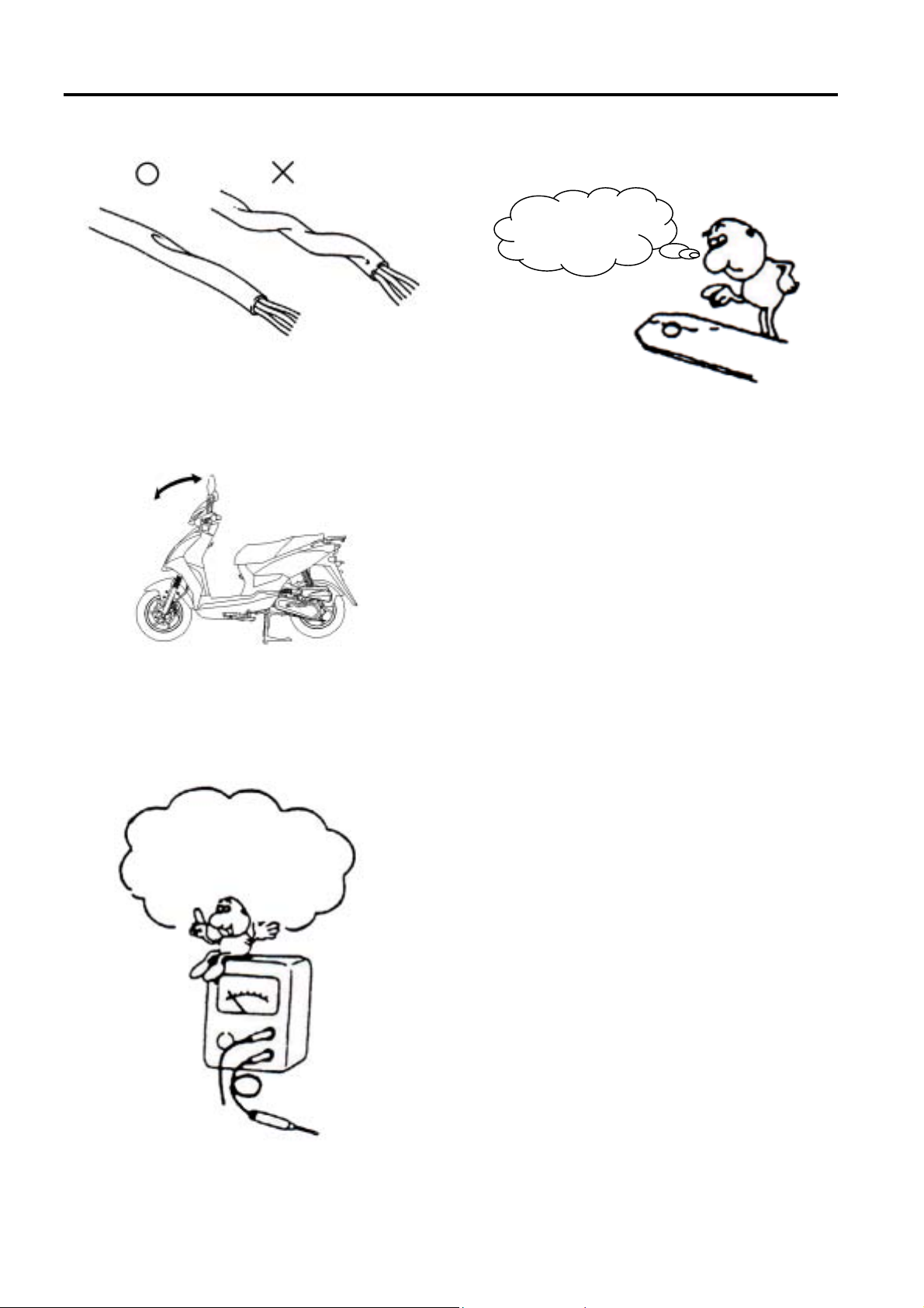
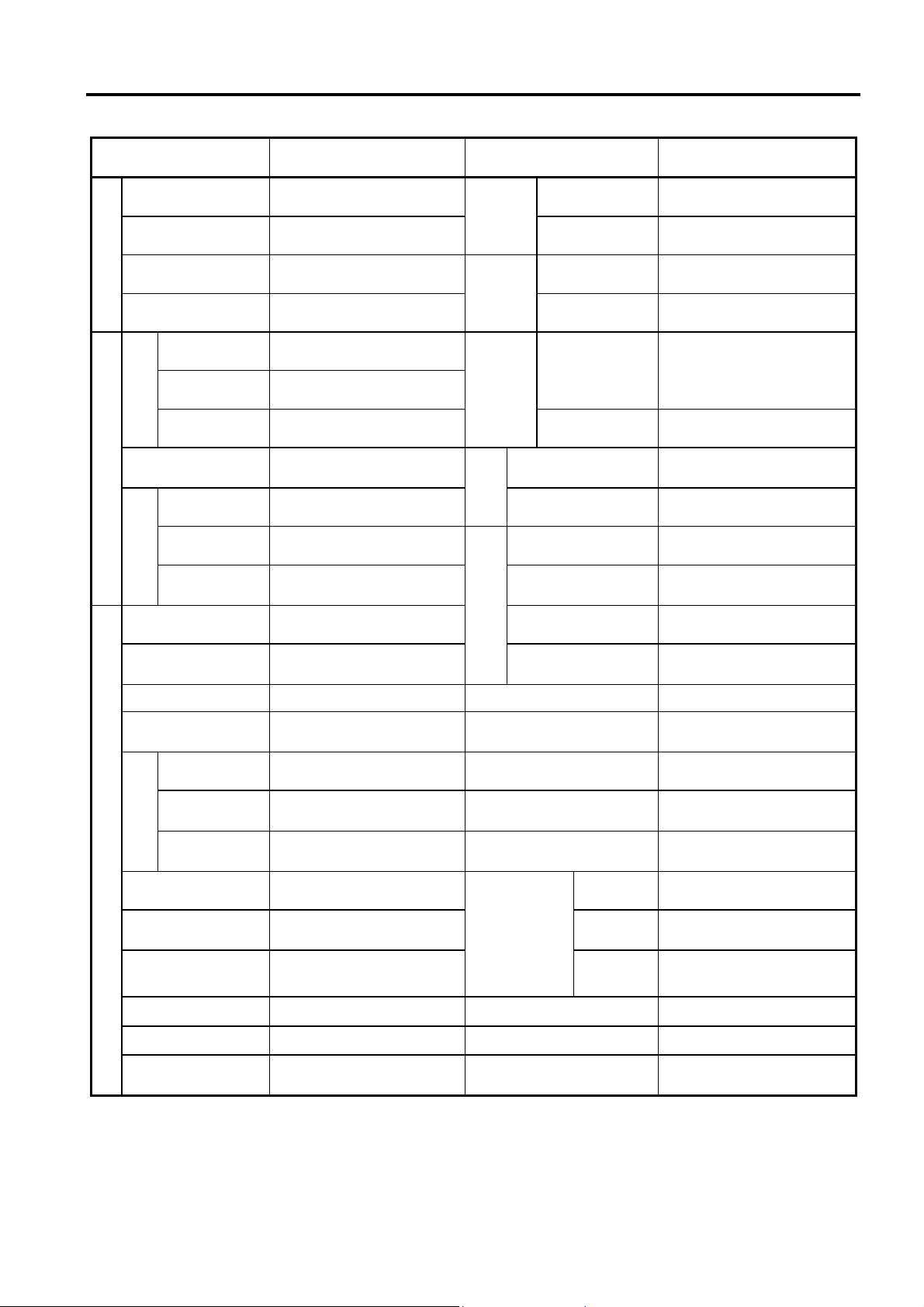
Do not let the wire harness been twisted as
installation.
Wire harnesses routed along the handlebar
should not be pulled too tight or have
excessive slack, be rubbed against or
interfere with adjacent or surrounding parts in
all steering positions.
Before operating a test instrument, operator
should read the operation manual of the
instrument. And then, conduct test in
accordance with the instruction.
Do you know how to set the
instrument to its measurement
position and the insert locations
of its two probes?
With sand paper to clean rust on connector
pins/terminals if found. And then conduct
connection operation later.
Clean rust.
1-8
Page 14
SYM 1. GENERAL INFORMATION/TROUBLE DIAGNOSIS
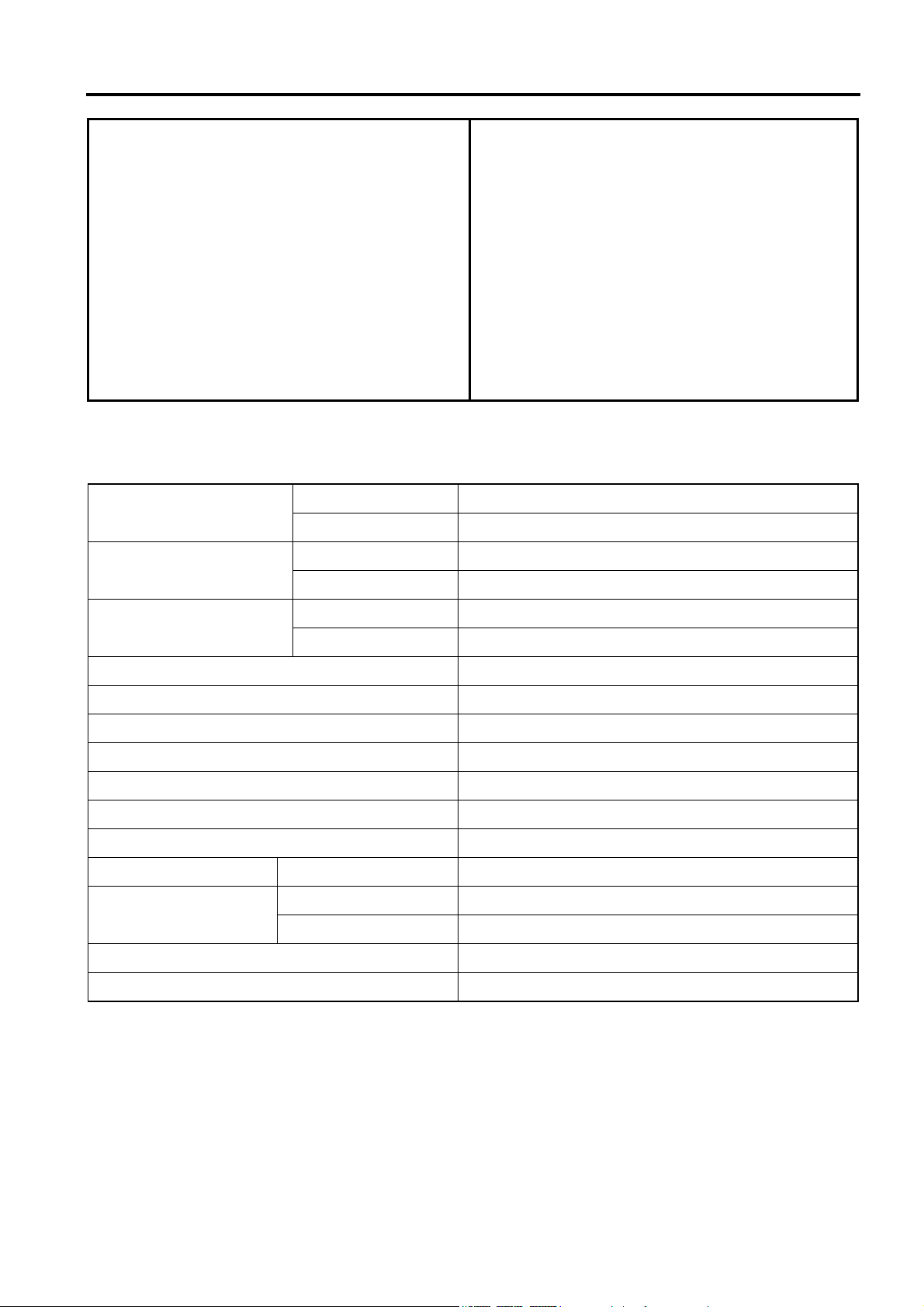
SPECIFICATIONS
MAKER SANYANG MODEL AAA(AV05W-6)
Overall Length 1906mm Front Telescopic fork
Overall Width 694mm
Overall Height 1138 mm Front 120/70-12(56J)
DIMENSION
Wheel Base 1327mm
Front 40kg
Rear 59kg
Curb Weight
WEIGHT
Total Weight
Installation and
Cycle/Cooling
Total 99kg
Passengers/
Weight
Front 84kg
Rear 125kg Primary Reduction BELT
Total 209kg
Type 4-STROKE ENGINE Clutch Centrifugal, dry type
arrangement
Fuel Used Petrol Speedometer 0 ~ 140 km/hr
Two men/150 kg Max. Speed 45km/h
Vertical, below center,
incline 80°
4-stroke/forced air
cooled
sion
System
Suspen
Tire
Specifi
cations
Brake
System
nce
Performa
Deceleration
Climb Ability 20° Below
Secondary
Reduction
equipment
Transmission C.V.T.
Horn 95~115dB(A)
Rear Single swing arm
Rear 130/70-12(56J)
Front DISK (ø 190 mm)
Rear DRUM (ø 110 mm)
GEAR
ENGINE
Bore φ39.0 mm Muffler Expansion & Pulse Type
Stroke 41.5 mm
Cylinder
Number/Arran
gement
Displacement 49.5 cc CO <1.0 g/km
Compression
Ratio
Max. HP 2.35KW/8500 rpm
Max. Torque 2.91N.m /6500 rpm Air Filtration Paper filter
Ignition C.D.I. Noise Emission < 71dB
Starting System Electrical & foot type
Single Cylinder/
horizontal
11.8:1 HC <1.2 g/km
Exhaust Pipe Position
and Direction
Lubrication System
Exhaust
Emission
Engine Weight(dry
weight)
NOx <1.2 g/km
Right side, and
Backward
forced-circulation&
splashing
23kg
1-9
Page 15
1. GENERAL INFORMATION/TROUBLE DIAGNOSIS SYM
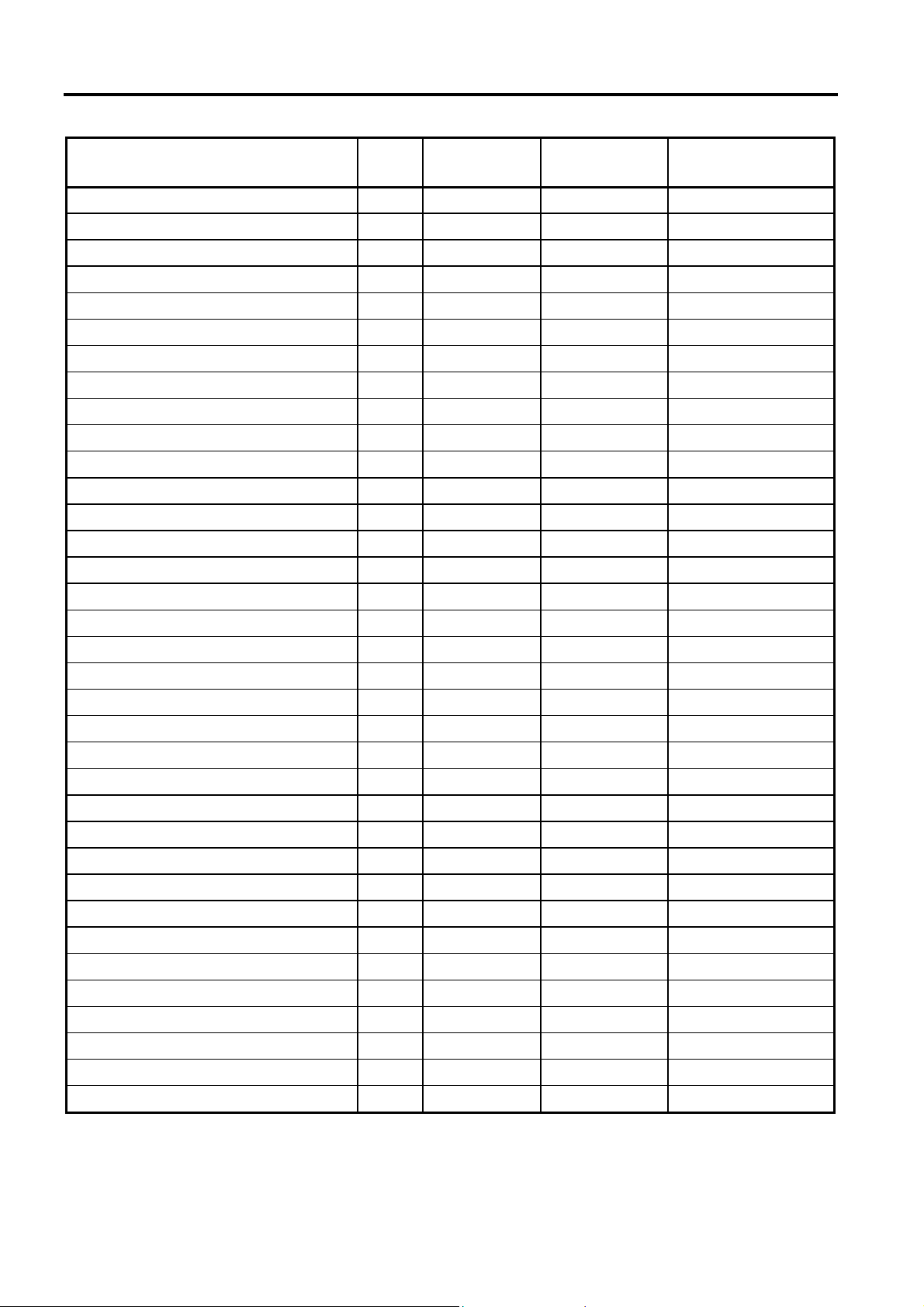
TORQUE VALUES (ENGINE)
ITEM Q'TY
Cylinder head bolts 4 6 0.8~1.2
Cylinder head nuts 4 8 1.8~2.2 Apply oil to thread
Cylinder/cylinder head two-ends bolts 4 7 0.7~1.1 Tighten to crankcase
Cam holder nut 4 7 0.8~1.2
Right crank case cover bolts 10 6 0.8~1.2
Pulse generator bolts 2 5 0.35~0.5
Valve adjustment fixing nuts 2 6 0.7~1.1 Apply oil to thread
Spark plug 1 10 1.0~1.4
Engine oil strainer cap 1 30 1.0~2.0
Gear oil draining plug 1 10 1.0~1.4
Gear oil filling bolt 1 10 1.0~1.5
Oil pump bolts 3 6 0.8~1.2
Oil pump drive sprocket nuts 1 6 0.8~1.2
Left crankcase cover bolts 10 6 0.8~1.2
Cylinder head cover bolts 4 6 0.8~1.2
Camshaft chain tensioner pivot 1 6 0.8~1.2 Hex socket bolt
THREAD DIA
(mm)
TORQUE
VALUE(Kg-m)
REMARKS
Camshaft chain adjuster bolts 2 6 1.0~1.4
Cooling fan bolts 4 6 0.8~1.2
Shroud A/B 2 6 0.8~1.2
RR. brake fixing nut 1 8 1.5~2.0
Flywheel nut 1 10 3.5~4.5
Transmission(Gear box) bolts 7 8 2.6~3.0
RR. brake arm bolt 1 6 0.7~1.1
Drive face nut 1 12 5.0~6.0
Drive pulley nut 1 10 3.5~4.5
A.C. generator flange bolt 2 6 0.8~1.2
Air/C connect bracket bolts 2 6 0.8~1.2
Start motor bolts 2 6 0.8~1.2
Brake arm bolt 1 6 0.7~1.1
Kick starter arm bolt 1 6 0.8~1.2
Carburetor nut 2 6 0.8~1.2
A.I. fixing hex cap nut 2 6 0.8~1.2
Crankcase bolts 1 6 0.8~1.2
Exhaust pipe bolts 2 8 3.0~3.6
Exhaust pipe connecting nuts 2 6 1.0~1.4
1-10
Page 16
SYM 1. GENERAL INFORMATION/TROUBLE DIAGNOSIS
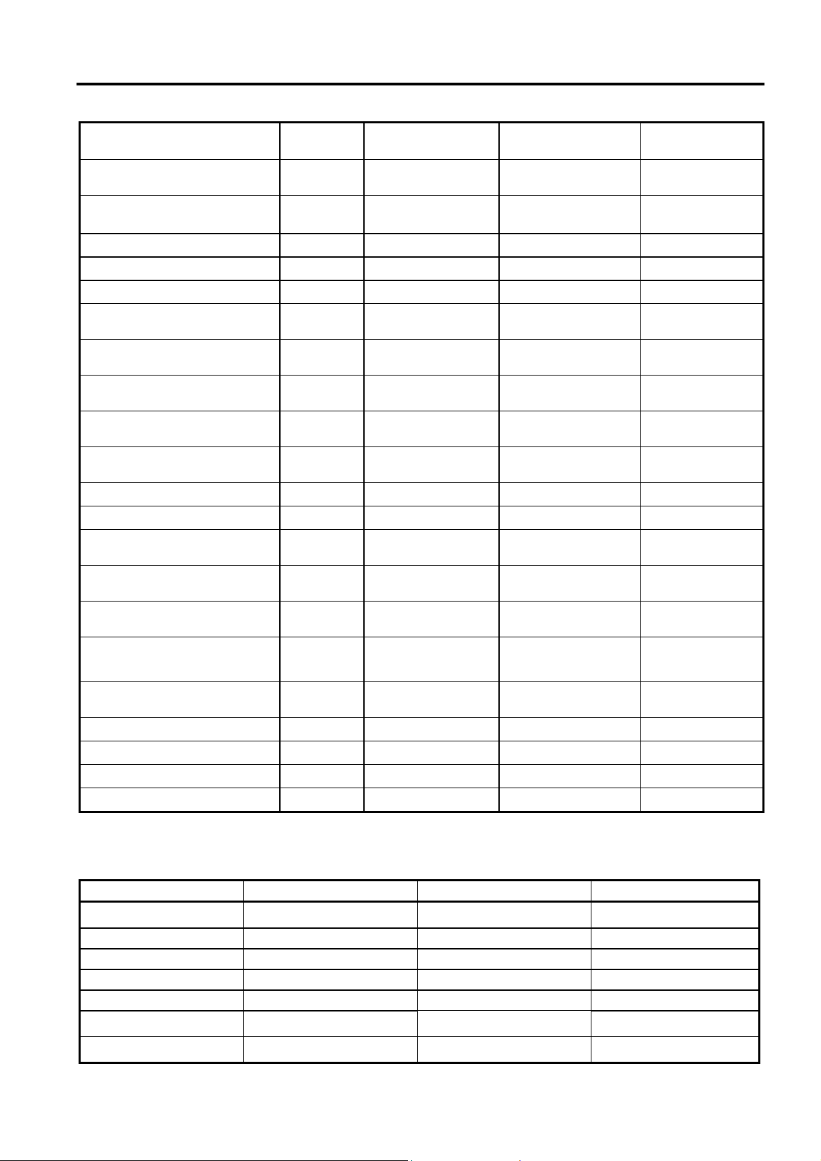
TORQUE VALUES (FRAME)
ITEM Q'TY
Mounting bolt for steering
handlebar
Mounting nut for steering rod 1 25.4 1.0~2.0
Cone seat for steering rod 1 25.4 0.2~0.3
Front wheel shaft nut 1 12 5.0~7.0
Rear wheel shaft nut 1 16 11.0~13.0
Wheel hub/rim mounting
nuts
Speedometer cable locking
screw
Front shock absorber
mounting bolts
Rear shock absorber upper
connection bolt
Rear shock absorber upper
connection bolt
Brake lever bolts 2 6 0.8~1.2
Front brake hose bolts 2 10 3.3~3.7
Front brake air-bleeding
valve
Front brake disc mounting
bolts
Front brake clipper mounting
bolts
Drum brake arm bolts
(front/rear)
Engine suspension bracket
bolts
Engine connection bolt 1 10 4.5~5.5 On engine side
Main standard nut 1 10 3.5~4.5
Foot-starting lever bolt 1 6 1.6~1.8
Air cleaner bolts 2 6 1.0~1.4
1 10 4.0~5.0
8 8 2.8~3.2
1 5 0.15~0.3
4 8 2.4~3.0
1 10 3.5~4.5
1 8 2.4~3.0
1 6 0.8~1.0
4 10 4.0~4.5
2 10 3.1~3.5
2 6 0.8~1.2
2 10 4.5~5.5 On frame side
THREAD DIA
(mm)
TORQUE
VALUE(Kg-m)
REMARKS
The torque values listed in above table are for more important tighten torque values. Please see
standard values for not listed in the table.
Standard Torque Values for Reference
TYPE TIGHTEN TORQUE TYPE TIGHTEN TORQUE
5mm bolt、nut
6mm bolt、nut
8mm bolt、nut
10mm bolt、nut
12mm bolt、nut
0.45~0.60kgf-m
0.80~1.20kgf-m 4mm screw 0.10~0.15kgf-m
1.80~2.50kgf-m 5mm screw 0.35~0.50kgf-m
3.00~4.00kgf-m
5.00~6.00kgf-m
3mm screw
6mm screw、SH nut
6mm bolt、nut
8mm bolt、nut
10mm bolt、nut
0.05~0.08kgf-m
0.70~1.10kgf-m
1.00~1.40kgf-m
2.40~3.00kgf-m
3.50~4.50kgf-m
1-11
Page 17
1. GENERAL INFORMATION/TROUBLE DIAGNOSIS SYM
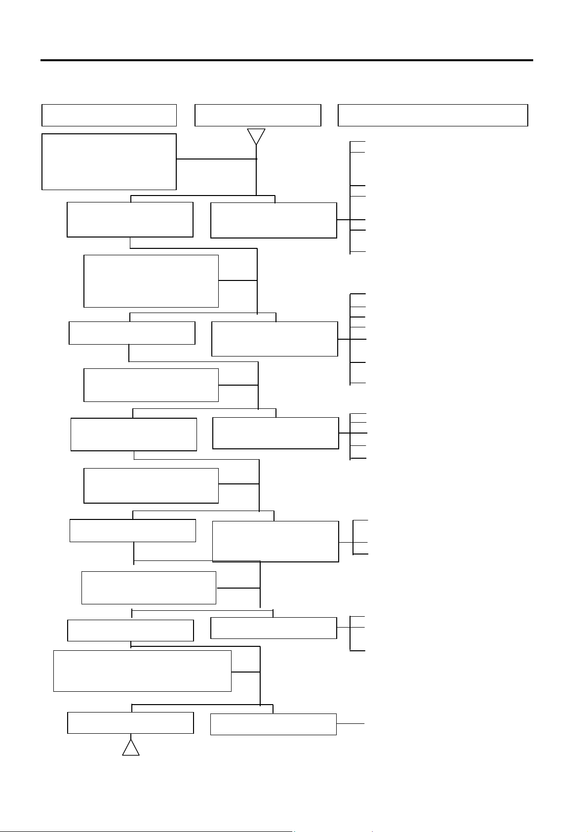
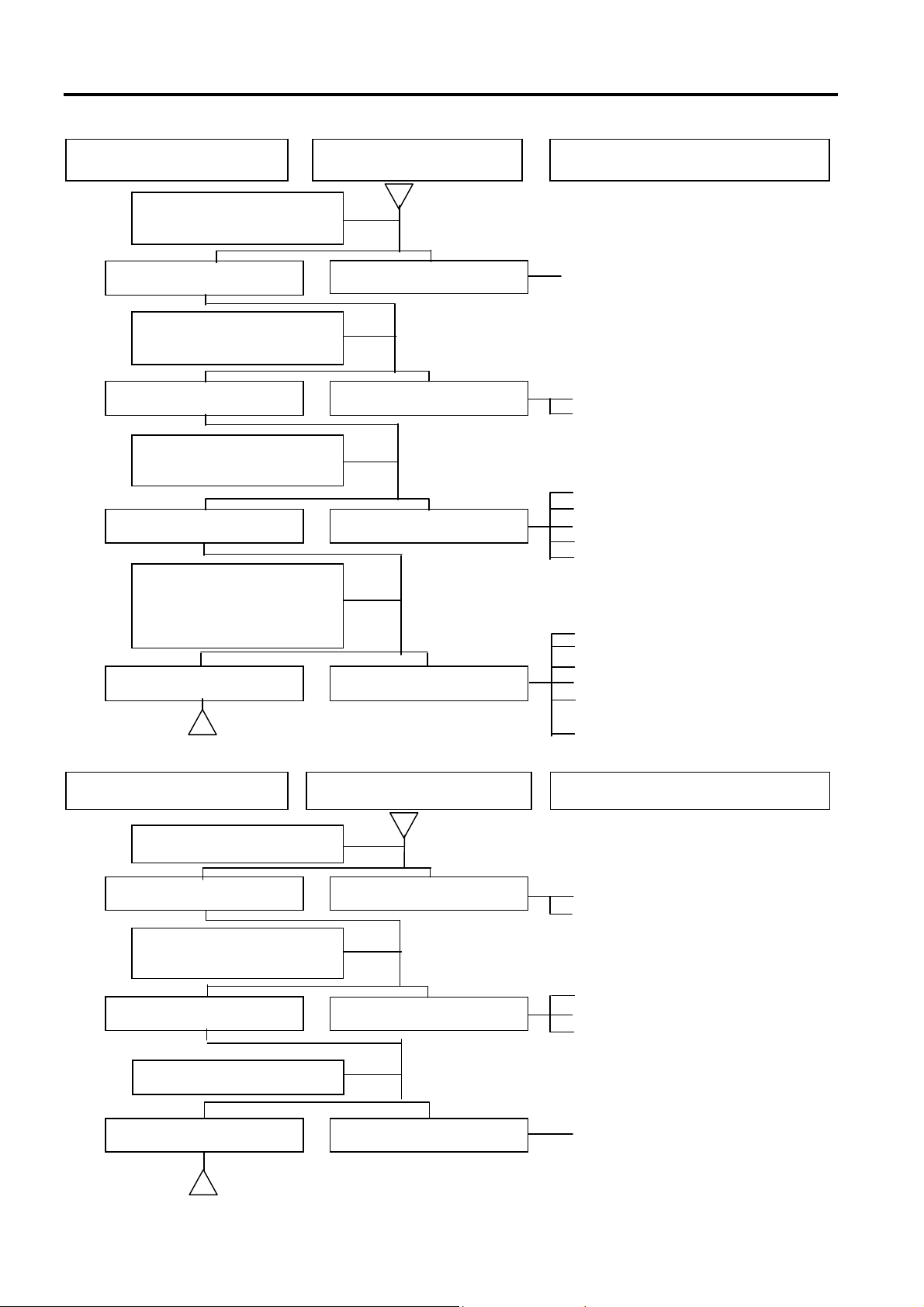
TROUBLES DIAGNOSIS
A. Engine hard to start or can not be started
Check and adjustment Fault condition
Loosen carburetor drain
bolt to check if there is
gasoline inside the
carburetor
Fuel supplied tom
carburetor sufficient
No fuel is supplied to
carburetor
Remove spark plug, install
it into spark plug cap, and
perform a spark test
against engine ground.
Check if sparks Weak sparks, no spark
at all
perform cylinder
compression pressure test.
Probable causes
1. No fuel in fuel tank
2. Check if the pipes, fuel tank to
carburetor and intake vacuum,
are clogged.
3. Float valve clogged
4. Lines in fuel tank evaporation
system clogged
5. Malfunction of fuel pump
6. Loosen or damaged fuel pump
vacuum hose
7. Fuel filter clogged
1. Malfunction of spark plug
2. Spark plug foul
3. Malfunction of CDI set
4. Malfunction of AC generator
5. Ignition coil is in open or short
circuit
6. Ignition coil leads open or short
circuit
7. Malfunction of main switch
cylinder compression
pressure normal
Re-start by following the
starting procedures
No ignition
Remove the spark plug
again and check it.
Dry spark plug
Remove carburetor after 30 minutes
and connect a hose onto fuel rich
circuit. Then blow the hose with air
Low compression
pressure or no pressure
There are some signs of
ignition, nut engine can
not be started
Wet spark plug
1. Piston ring seized
2. Malfunction of cylinder valves
3. Worn cylinder and piston ring
4. Cylinder gasket leak
5. Sand hole in compression parts
1. Malfunction of throttle valve
operation
2. Air sucked into intake manifold
3. Incorrect ignition timing
1. Fuel level in carburetor too high
2. Malfunction of throttle valve
operation
3. Throttle valve opening too wide
1-12
Blowing in normal
Blowing clogged
1. Malfunction of automatic bystarter
Page 18
SYM 1. GENERAL INFORMATION/TROUBLE DIAGNOSIS
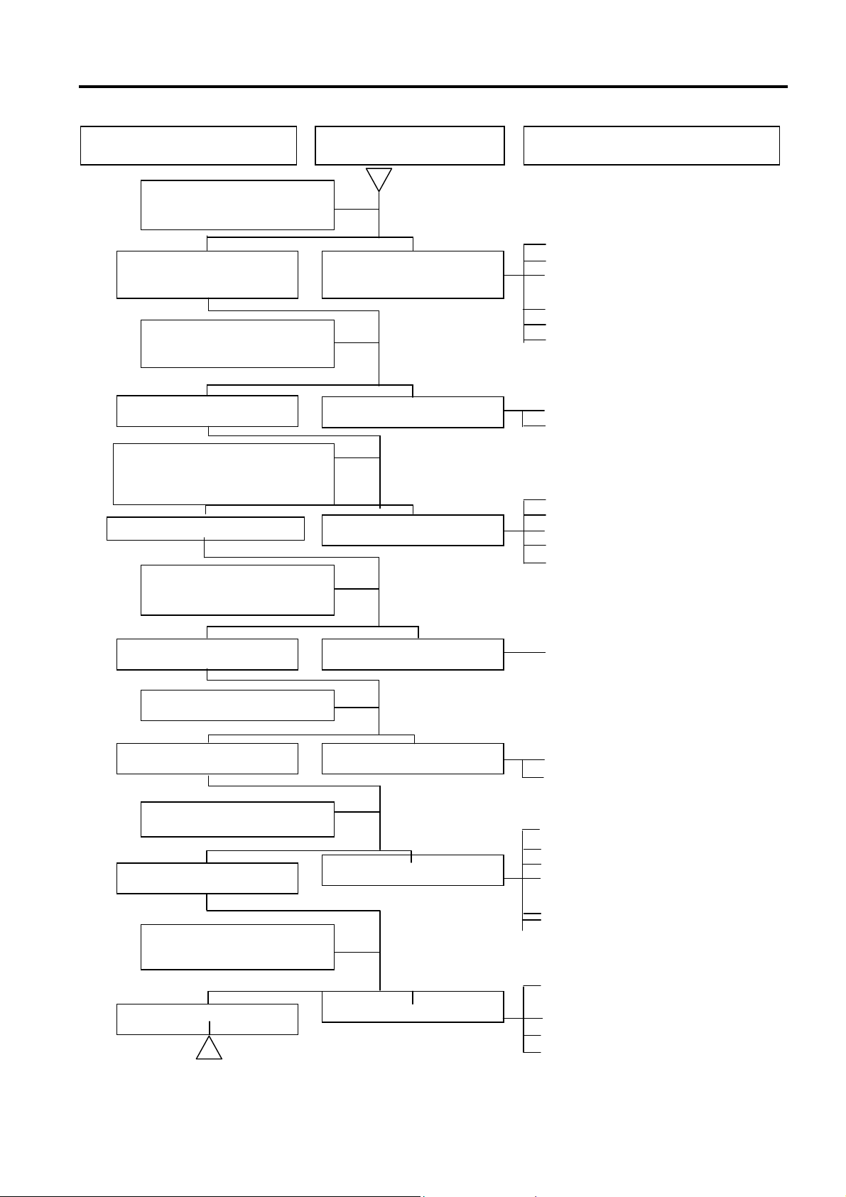
B. Engine run sluggish (Speed does not pick up, lack of power)
Check and adjustment
Fault condition
Probable causes
Try gradual acceleration
and check engine speed
Engine speed can be
increased.
Check ignition timing
(Using ignition lamp)
Ignition timing correct
Check cylinder compression
pressure (using compression
pressure gauge)
Compression pressure correct
Check if carburetor jet is
clogged
Engine speed can not be
increased.
Incorrect ignition timing
No compression
1. Air cleaner clogged
2. Poor fuel supply
3. Lines in fuel tank evaporation
system clogged
4. Exhaust pipe clogged
5. Fuel level too low in carburetor
6. Fuel nozzle clogged in
1. Malfunction of CDI
2. Malfunction of AC alternator
1. Cylinder & piston ring worn out
2. Cylinder gasket leaked
3. Sand hole in compression parts
4. Valve deterioration
5. Seized piston ring
No clogged Clogged
1. Remove foreign
Remove spark plug
No foul or discoloration Fouled and discoloration
Check if engine over heat
Normal
Engine overheat
Continually drive in
acceleration or high speed
1. Remove dirt
2. Incorrect spark plug heat range
1. Piston and cylinder worn out
2. Lean mixture
3. Poor fuel quality
4. Too much carbon deposited in
combustion chamber
5. Ignition timing too advanced
6. Poor circuit on the cooling
system
1. Too much carbon deposited in
No knock
Knock
combustion chamber
2. Lean mixture
3. Poor fuel quality
4. Ignition timing too advanced
1-13
Page 19
1. GENERAL INFORMATION/TROUBLE DIAGNOSIS SYM
C. Engine runs sluggish (especially in low speed and idling)
Check and adjustment Fault condition Probable causes
Check ignition timing
(using ignition lamp)
Normal
Adjust the air screw of
carburetor
Abnormal
1. Incorrect ignition timing (malfunction
of CDI or AC alternator)
Good Poor
Air sucked through
carburetor gasket
No air sucked Air sucked
Remove spark plug, install
spark plug into spark plug
cap and perform spark test
against engine ground
Good spark Poor
1. Rich mixture (loosen the screw)
2. Lean mixture (tighten the screw)
1. Poor heat insulation gasket
2. Carburetor lock loose
3. Poor intake gasket
4. Poor carburetor O-ring
5. Vacuum hose crack
1. Spark plug fouled
2. Malfunction of CDI
3. Malfunction of AC generator
4. Malfunction of ignition coil
5. Open or short circuit in spark plug
leads
6. Malfunction of main switch
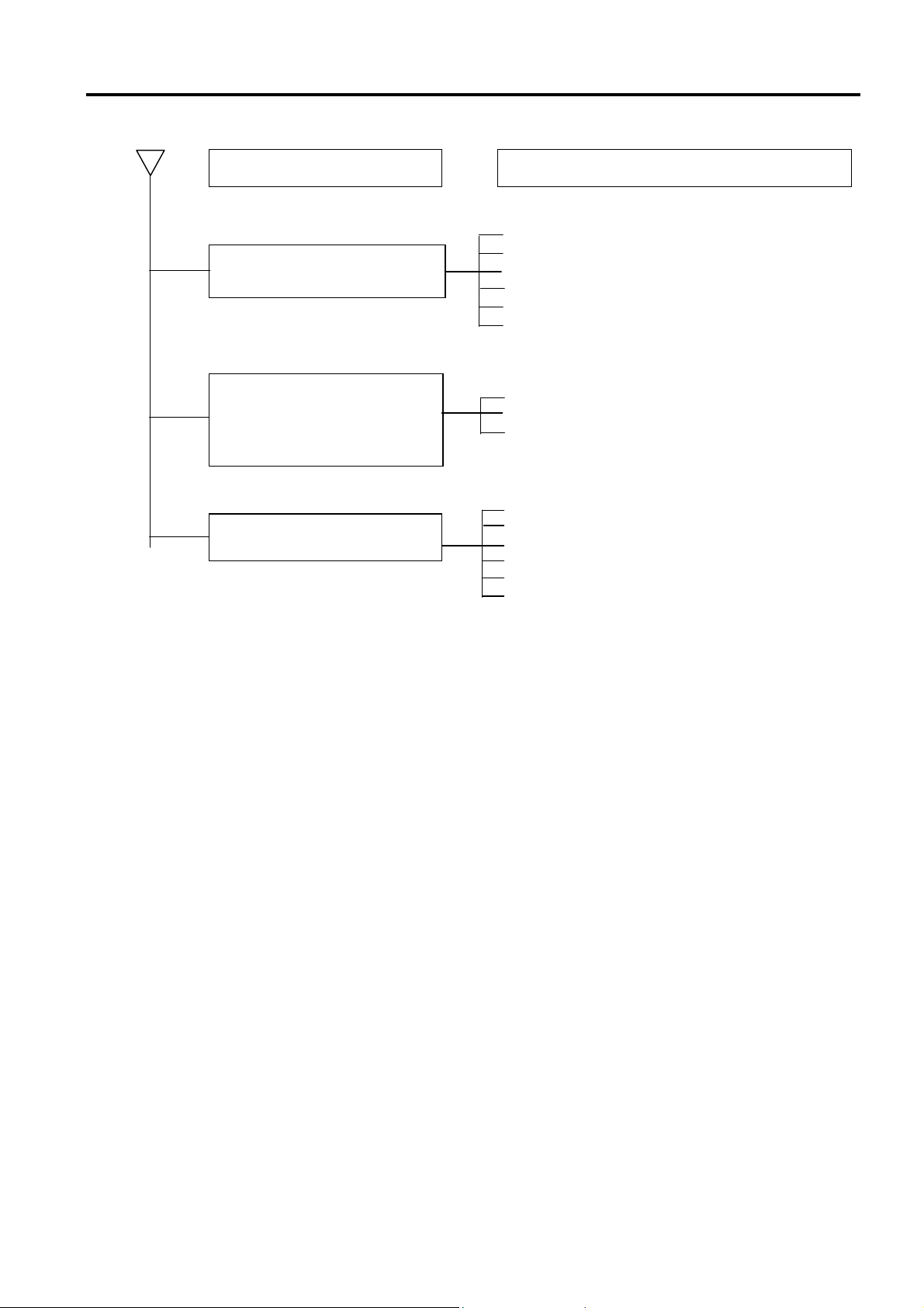
D. Engine runs sluggish (High speed)
Check and adjustment Fault condition Probable causes
1-14
Check ignition timing
Normal Abnormal
Check for fuel supplying
system in automatic fuel cup
Good
Check if carburetor clogged
No clogged Clogged
Poor
1. Malfunction of CDI
2. Malfunction of AC alternator
1. Insufficient fuel in fuel tank
2. Fuel filter clogged
3. Restricted fuel tank vent
1. Cleaning
Page 20
SYM 1. GENERAL INFORMATION/TROUBLE DIAGNOSIS
E. CLUTCH, DRIVING AND DRIVING PULLEY
FAULT CONDITIONS PROBABLE CAUSES
Engine can be started but
motorcycle can not be moved.
1. Driving belt worn out or deformation
2. Driving disk damaged
3. Driving pulley spring broken
4. Clutch ling broken
5. Driving slide-shaft gear groove broken
6. Transmission gear damaged
Engine running and misfire as
motorcycle initial forward moving
or jumping suddenly (rear wheel
rotating as engine in running)
1. Clutch ling spring broken
2. Clutch outer stick with clutch balance weights
3. Connection parts in clutch and shaft worn out
or burned
Poor initial driving ( Poor climbing
performance)
1. Driving belt worn out or deformation
2. Balance weight roller worn out
3. Driving sliding gear shaft worn out
4. Driving disk spring deformation
5. Driving sliding gear shaft worn out
6. Greased in driving belt and sliding gear.
1-15
Page 21
1. GENERAL INFORMATION/TROUBLE DIAGNOSIS SYM
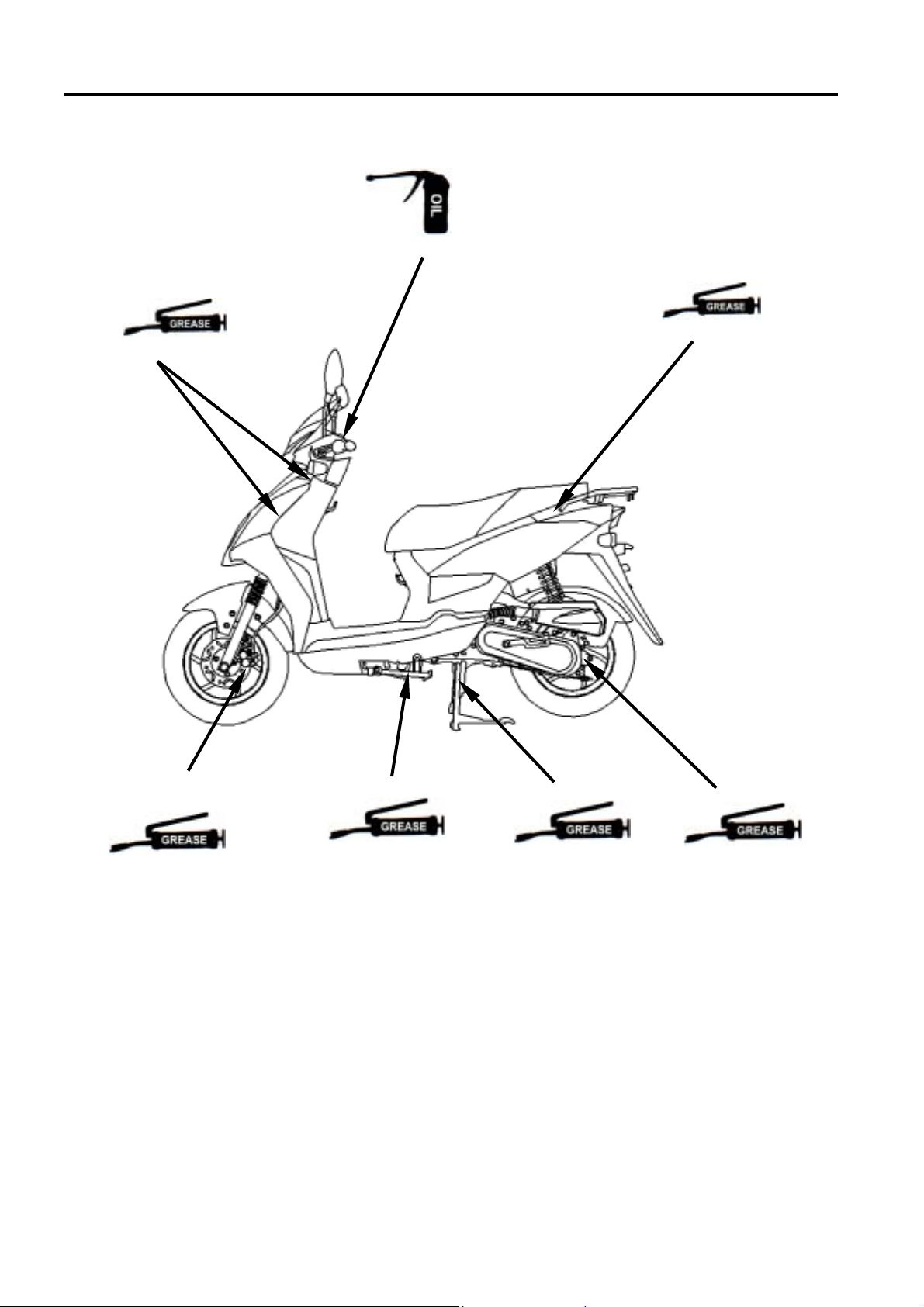
LUBRICATION POINTS
Steering shaft bearing
Acceleration cable/ Front & rear brake lever pivot
Seat lock
Speedometer gear /
Front wheel bearing
Side stand shaft
Main stand shaft
Rear wheel bearing
1-16
Page 22
SYM 2. MAINTENANCE INFORMATION
PRECAUTIONS IN OPERATION .......2-1
PERIODICAL MAINTENANCE SCHEDULE........2-2
LUBRICATION SYSTEM....................2-3
FUEL SYSTEM...................................2-4
AIR CLEANER....................................2-5
THROTTLE VALVE OPERATION ......2-5
VALVE CLEARANCE INSPECTION & ADJUSTMENT ......2-6
CARBURETOR IDLING SPEED ADJUSTMENT .2-7
IGNITION SYSTEM/SPARK PLUG ..2-8
CYLINDER COMPRESSION PRESSURE
.2-9
PRECAUTIONS IN OPERATION
Specification
Fuel Tank Capacity
Engine Oil
Main 5200 c.c.
auxiliary 1500 c.c.
capacity 850 c.c.
change 750 c.c.
DRIVING SYSTEM.............................2-9
STEERING SYSTEM .........................2-10
SUSPENSION SYSTEM .................... 2-10
FRONT DISK BRAKE SYSTEM ......... 2-11
DRUM BRAKE SYSTEM.................... 2-13
WHEEL/TIRE......................................2-14
BATTERY........................................... 2-15
HEADLIGHT ADJUSTMENT.............. 2-15
NUTS、BOLTS TIGHTEN.................. 2-15
Transmission Gear oil
capacity 110 c.c.
change 100 c.c.
Clearance of throttle valve 2~6 mm
Spark plug A7RC Gap: 0.6~0.7 mm
“F” Mark in idling speed Before TDC 13º / 2200 rpm
Full timing advanced Before TDC 26º / 8000 rpm
Idling speed 2100±100 rpm
Cylinder compression pressure 11.8±0.2 kg/cm²
Valve clearance: IN/EX 0.03/0.05±0.02 mm
Tire dimension front / rear 120/70-12 / 130/70-12
single Front: 1.75 kg/cm² rear: 2.00 kg/cm²
Tire pressure (cold)
Two persons Front: 1.75 kg/cm² rear: 2.25 kg/cm²
Battery 12V6Ah (MF battery)
Play of drum brake lever 10~20 mm
2-1
Page 23
2. MAINTENANCE INFORMATION SYM
PERIODICAL MAINTENANCE SCHEDULE
Mainte
nance
Code
☆Air cleaner
1
☆2nd air jet leaner
2
☆Fuel filter
3
☆Oil filter
4
☆Engine oil change
5
6 Tire pressure
7 Battery inspection
8 Brake & free play check
9 Steering handle check
10 Cushion operation check
11 Every screw tightening check
12 Gear oil check for leaking
☆Spark plug check or change
13
☆Gear oil change
14
15 Frame lubrication
16 Exhaust pipe
☆Ignition timing
17
☆Emission check in Idling
18
☆Throttle operation
19
☆Engine bolt tightening
20
☆CVT driving device (belt﹞
21
☆CVT driving device (roller)
22
23 Lights/electrical equipment/mutli-meters
24 Main/side stands & springs
25 Fuel pipes
27 Cam chain
☆Valve clearance
28
☆Crankcase vapor control System
29
☆Crankcase blow-by over-flow pipe
30
☆2nd air jet system
31
☆vapor control system
32
Code: I ~ Inspection, cleaning, and adjustment R ~ Replacement C ~ Cleaning (replaced if necessary) L ~ Lubrication
Have your motorcycle checked, adjusted, and recorded maintenance data periodically by your SYM Authorized Dealer to
maintain the motorcycle at the optimum condition
The above maintenance schedule is established by taking the monthly 1000 kilometers as a reference which ever comes
first.
Remarks:
1. These marks “☆” in the schedule are emission control items. According to EPA regulations, these items
must be perform normally periodical maintenance following the use r manual instructions. They are
prohibited to be adjusted or repaired by unauthorized people. Otherwise, SYM is no responsible for the
charge.
2. Clean or replace the air cleaner element more often when the motorcycle is operated on dusty roads or in the
Heavily- polluted environment.
3. Maintenance should be performed more often if the motorcycle is frequently operated in high speed and after the
motorcycle has accumulated a higher mileage.
4. Preventive maintenance
a. Ignition system - Perform maintenance and check when continuous abnormal ignition, misfire, after-burn,
overheating occur.
b. Carbon deposit removal - Remove carbon deposits in cylinder head, piston heads, exhaust system when power is
obvious lower than ever.
c. Replace worn out pistons, cylinder head.
Item Initial 300KM
I C C R
I C C R
I I R
C C C
R
I I
I I
I I
I I
I I
I I
I I
I I R
R
L
I I
I I
A I
I I
I I
I R
C
I I
I I
I I
I I
I A
I C
I
I I C
I
1 Month
Every1000KM
3 month
Every3000KM
Replacement for every 1000km
Replacement for every 5000km
Replacement for every 2000km
6 month
Every6000KM
1 year
Every12000K
M
2-2
Page 24
SYM 2. MAINTENANCE INFORMATION
r
r
LUBRICATION SYSTEM
Engine Oil Capacity
Caution
The vehicle must be parked on a level
ground when checking oil capacity.
Run the engine for 2-3 minutes then stop,
wait about 2-3 more minutes allowing
engine oil to settle before checking the oil
level.
Remove dipstick to check the oil level. If oil
level is below the lower limit mark, add oil to
the specified upper limit mark.
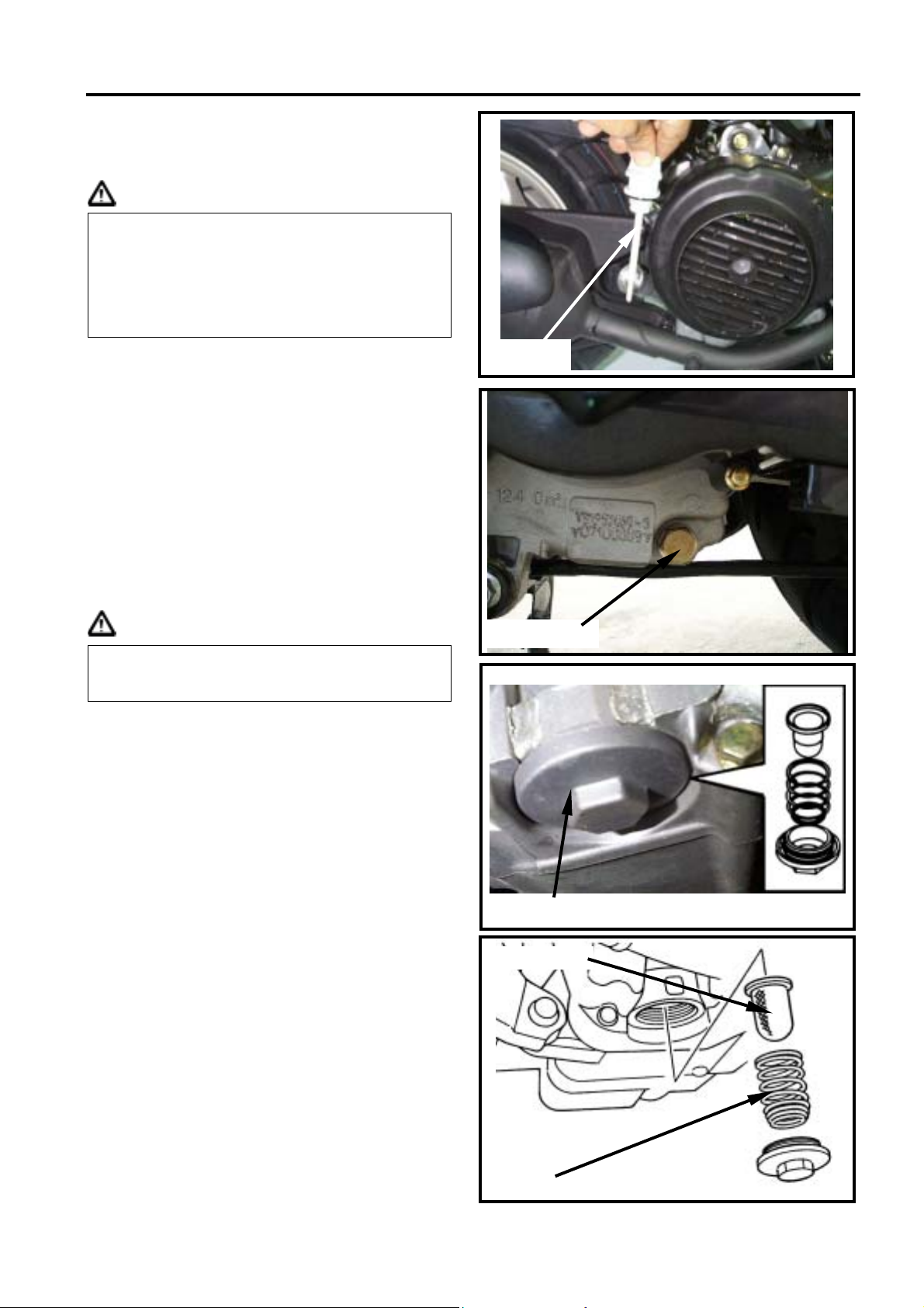
Oil change
Shut off the engine and remove dipstick.
Remove the oil drain plug on the bottom-left
of crankcase to drain oil.
After draining out oil, clean oil plug and its
+-gasket and reinstall. Replace the gasket if
it is damaged.
Torque value1.0~1.5 kgf-m
Dipstick
Caution
Warm up the engine. This will make the oil
flow out easily.
Add oil to the specified capacity.
Oil Viscosity: SAE 10W-30, recommended
using King-Mate serial oil.
Engine oil capacity:
Disassembly: 850cc
Change: 750cc
When checking for oil leak, run the engine at
idle speed for a few minutes, then check oil
capacity with dipstick.
Cleaning the oil strainer
Drain oil from engine, remove the strainer
cover, spring and strainer.
If there is an accumulation on the screen,
wash it off with suitable solvent
(recommended using compressed air).
Check O-ring for damage, replace if
necessary.
Reinstall strainer, spring, O-ring and strainer
cover.
Torque value: 1.0~2.0 kgf-m
Oil drain plug
strainer cove
oil straine
spring
2-3
Page 25
2. MAINTENANCE INFORMATION SYM
r
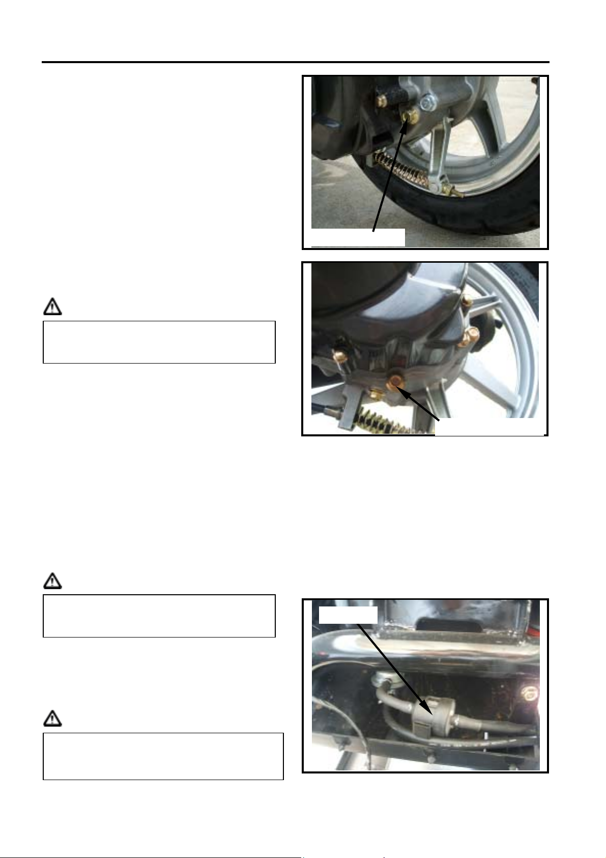
Gear Oil
Inspection
Check gear oil if leaking.
Park the motorcycle with main stand on flat
level place.
Turn off engine and remove the gear oil
draining plug.
Place a measurement cup under the draining
hole.
Remove the oil drain plug and drain gear oil
into a measurement cup.
Check gear oil if enough.
Replacement
At first, remove the gear oil refilling bolt, and
then remove the draining plug.
Install the draining plug after drained oil out.
Torque value: 1.0~1.5 kgf-m
Caution
Inspect if washer is in good condition.
Replace it with new one if it was deformed
or damaged.
Fill out gear oil to specified quantity from the
engine oil filling hole.
Install the oil filling bolt.
Torque value: 1.0~1.5 kgf-m
Quantity: 90 c.c.
Recommended: King-Mate HYPOID GEAR
OIL ( #140 ).
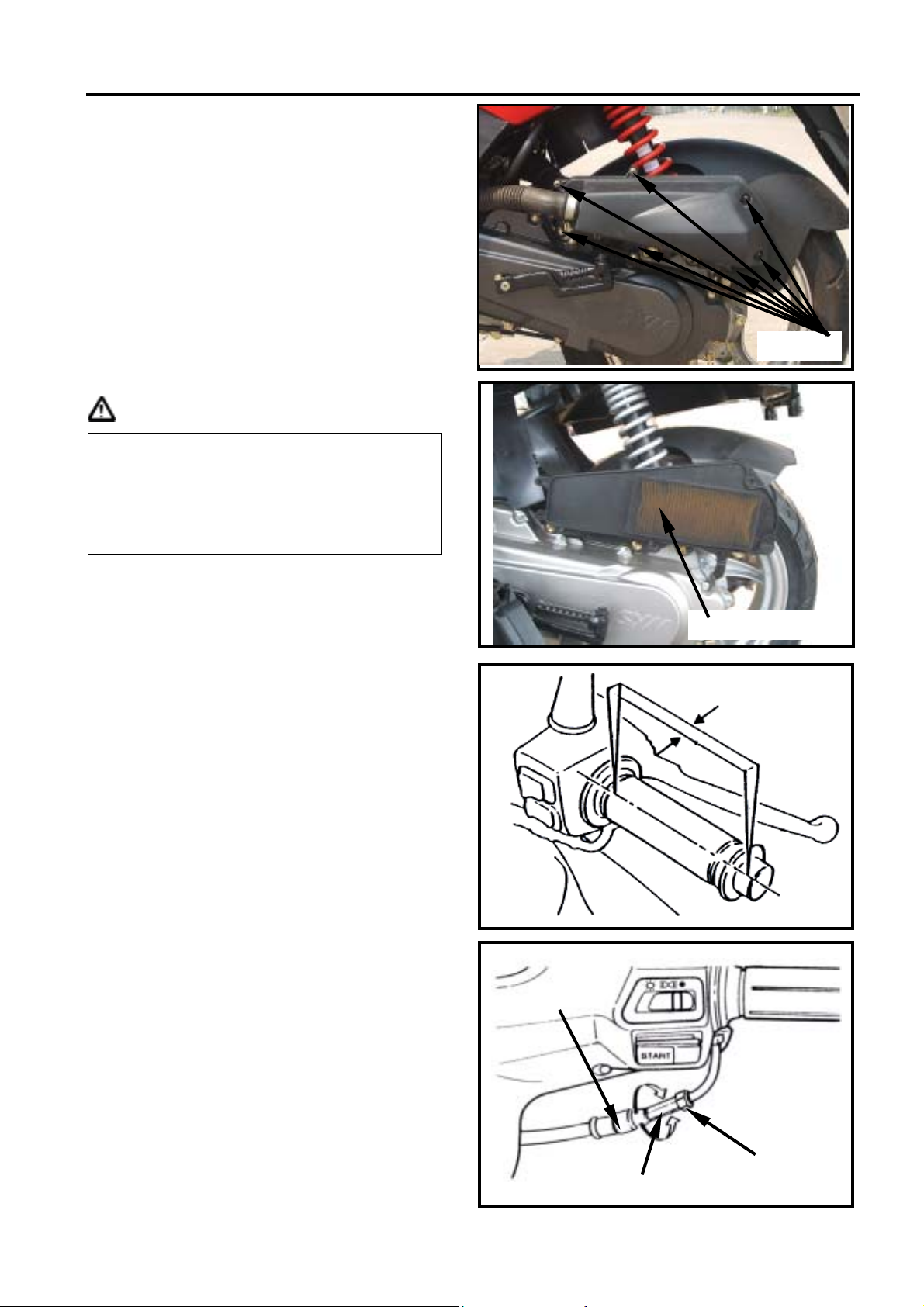
Fuel System
Fuel Pipe
Remove luggage box, rear center cover,
body cover, and rear fender, as well as front
inner box.
Check all pipes, and replace it when they are
deterioration, damage or leaking.
Gear oil refilling bolt
Gear oil draining plug
Warning
Gasoline is a low ignition material so any
kind of fire is strictly prohibited as dealing
it.
Fuel filter
Remove the fuel tank.
Remove fuel pipe from the fuel filter.
Replace the fuel filter with new one.
Install the fuel filter.
Caution
The arrow on the fuel filter means the flow
direction of fuel and check it if leaking after
installation.
2-4
Fuel filte
Page 26
SYM 2. MAINTENANCE INFORMATION
AIR CLEANER
Element
Remove 7 screws from the air cleaner cover.
Remove element of air cleaner (2 screws).
Check the element if dirt or damaged.
Replace it with new one if dirt or damaged.
Caution
Air cleaner element contains a paper
made filter so do not try to clean it.
Make sure that the air cleaner cover had
been installed properly after installation.
screws×7
THROTTLE VALVE OPERATION
Have a wide open of throttle valve as handle
bar in any position and release it to let back
original (full closed) position.
Check handle bar if its operation is smooth.
Check throttle valve cable and replace it if
deteriorated, twisted or damaged.
Lubricate the cable if operation is not
smooth.
Measure handle bar free play in its flange
part.
Free play:2~6 mm
Adjustment can be done in either ends.
Secondary adjustment is conducted from top
side.
Remove rubber boot, loosen fixing nut, and
then adjust it by turning the adjustment nut.
Air cleaner element
2~6 mm
Rubber boot
Fixing nut
Adjustment nut
2-5
Page 27
2. MAINTENANCE INFORMATION SYM
Primary adjustment is conducted from button
side.
Loosen fixing nut, and adjust by turning the
adjustment nut.
Tighten the fixing nut, and check
acceleration operation condition.
Caution
When always riding in rainy area or full
throttle position, maintenance period must
be shorted. The deposits can be seen in
the transparent section of draining hose.
Adjustment nut
Fixing nut
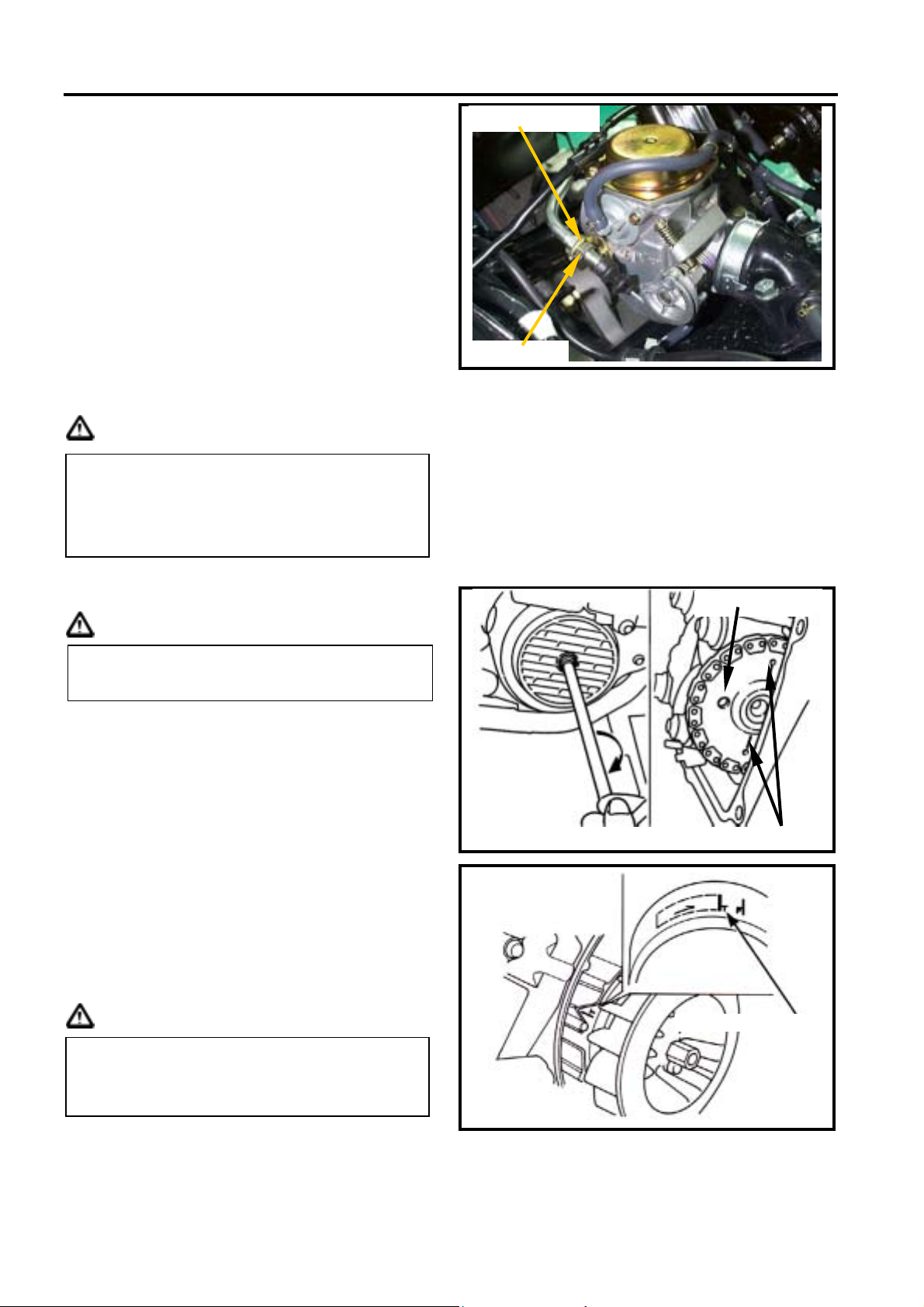
VALVE CLEARANCE ADJUSTMENT
Caution
Checks and adjustment must be performed
when engine is cold (below 35℃).
Remove luggage box and front center cover.
Remove the left body cover & left side cover.
Remove cylinder head cap.
Remove the ignition timing check hole on the
cooling fan cover.
With “T” type wrench, turn crankshaft in
clockwise motion so that mark (“T”) on the
generator flywheel aligns with the mark on
the crankshaft, and camshaft is at TDC
position also as same as level of cylinder
head top-end. A single hole on camshaft
sprocket is forward to up. (Piston is at TDC
position in the compression stroke.)
Caution
The crankshaft can not be rotated in
counter-clockwise to prevent from damage
so that valve clearance can not be
measured.
Inspection hole
TDC mark
Ignition timing mark
2-6
Page 28
SYM 2. MAINTENANCE INFORMATION
VALVE CLEARANCE INSPECTION
AND ADJUSTMENT
Check & adjust valve clearance with feeler
gauge.
Valve clearance (IN/EX): 0.03/0.03±0.2 mm
Loosen fixing nut and turn the adjustment
nut for adjustment.
Caution
It has to make sure that valve-rocker arm is
be adjusted to standard level when
adjusting it, and re-check the valve
clearance after tightened the fixing nut.
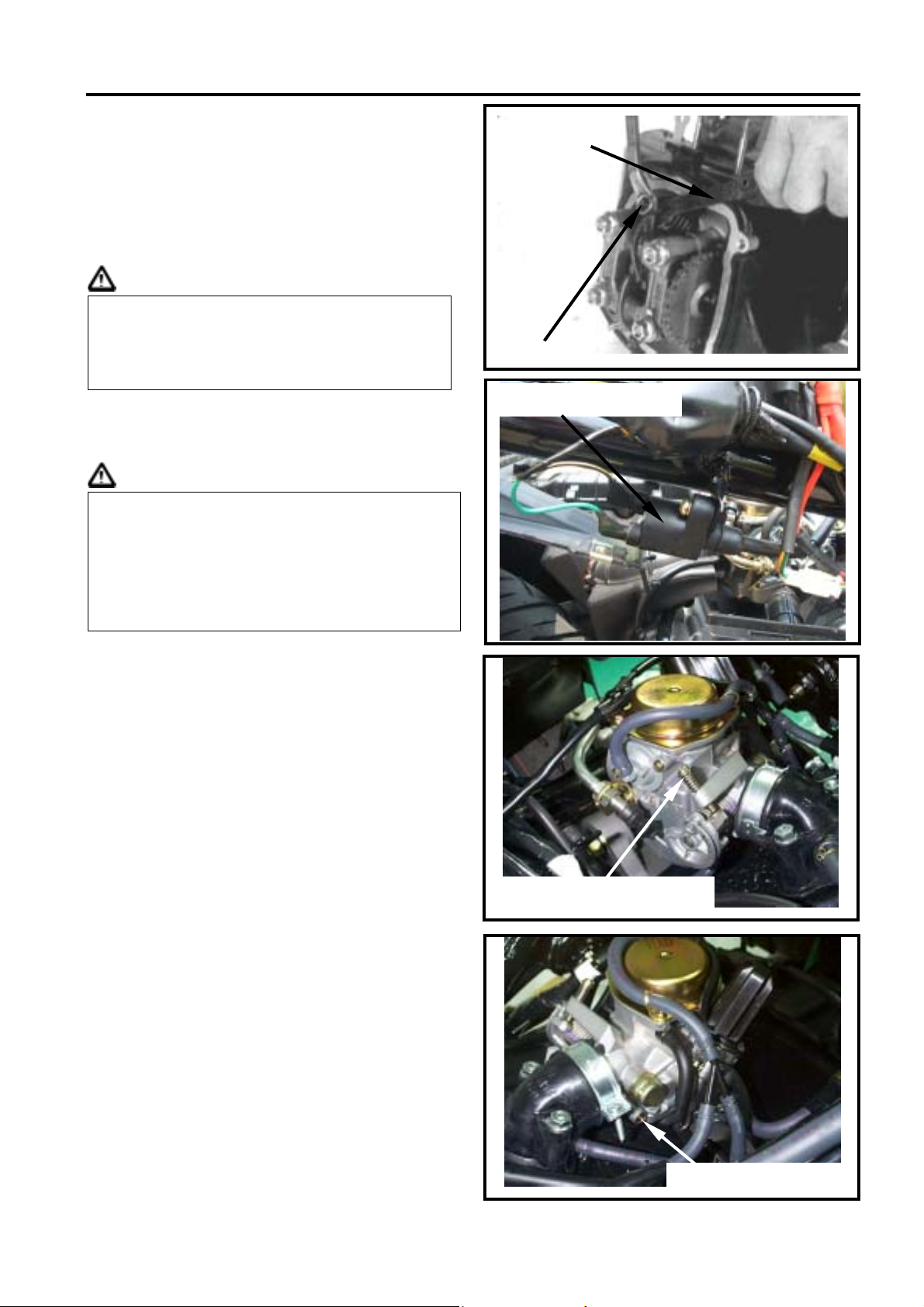
CARBURETOR IDLE SPEED
ADJUSTMENT
Caution
Inspection & adjustment for idle speed
have to be performed after all other parts
in engine that needed adjustment have
been adjusted.
Idle speed check and adjustment have to
be done after engine is being warm up
(around 10 minutes).
Park the motorcycle with main stand and
warn up engine.
Open the carburetor cover from the luggage
box.
Turn the throttle valve stopper screw to
specified idle speed.
Specified idle speed: 2100±100 rpm
Emission adjustment in Idle speed
Warm up the engine for around 10 minutes
and then conduct this adjustment.
1. Connect the tachometer onto engine.
2. Adjust the idle speed adjustment screw and
let engine runs in 2100±100 rpm.
3. Insert the exhaust sampling muffler of
exhaust analyzer into the front section of
exhaust pipe. Adjust the air adjustment
screw so that emission value in idle speed
is within standard.
4. Slightly accelerate the throttle valve and
release it immediately. Repeat this for 2~3
times.
5. Read engine RPM and value on the
exhaust analyzer. Repeat step 2 to step 4
procedures until measured value within
standard.
Exhaust Emission: CO: <1.0g/km
HC: <1.2g/km
NOx:<1.2g/km
Feeler gauge
Fixing nut
Ignition coil cable
Throttle valve stopper screw
Air adjustment screw
2-7
Page 29
2. MAINTENANCE INFORMATION SYM
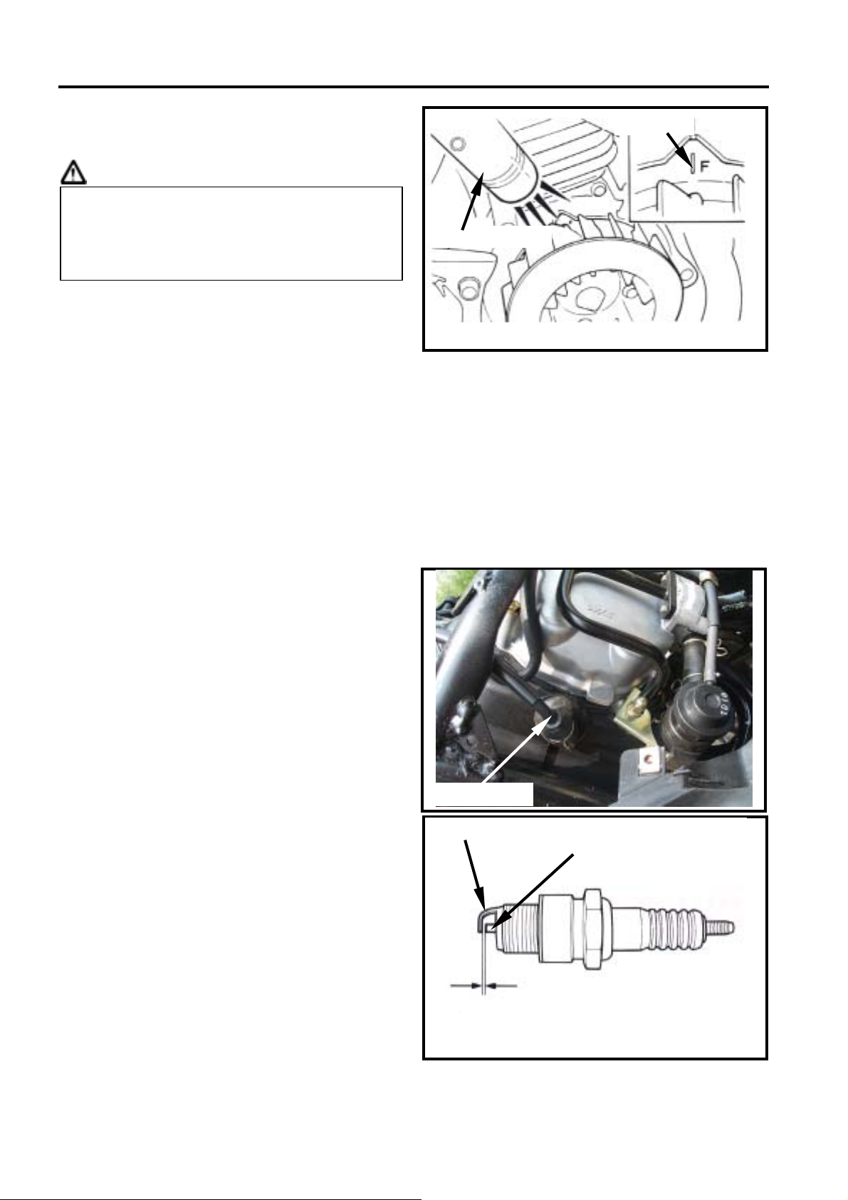
IGNITION SYSTEM
Ignition timing
Caution
C.D.I ignition system is set by manufacturer
so it can not be adjusted.
Ignition timing check procedure is for
checking whether C.D.I. function is in normal
or not.
Remove ignition timing hole cap located on
the cooling fan cap, or remove the cooling
fan cap.
Check ignition timing with ignition light.
Start engine and set engine idle speed in
1700 rpm, and if the mark aligns with the “F”,
then it means that ignition timing is correct.
Increase engine speed to 8000 rpm to check
ignition timing advance. If the detent aligns
with advance mark “װ”, then it means ignition
timing advance is in functional. If not,
check CDI set, pulse flywheel, and pulse
generator. Replace these components if
malfunction of these parts are found.
F mark
Ignition light
SPARK PLUG
Appointed spark plug: TORCH A7RC
Remove luggage box.
Remove center cover.
Remove spark plug cap.
Clean dirt around the spark plug hole.
Remove spark plug.
Measure spark plug gap.
Spark plug gap: 0.6~0.7 mm
Carefully bend ground electrode of the plug
to adjust the gap if necessary.
Screw the park plug into the plug hole with
hands, then tighten the plug with a wrench to
prevent from damaging the spark plug's
thread.
Torque value: 1.0~1.4 kgf-m
Connect spark plug cap.
Spark plug
Side electrode
Center electrode
2-8
0.6~0.7mm
Page 30
SYM 2. MAINTENANCE INFORMATION
CYLINDER COPMRESSION PRESSURE
Warn up engine and then turnoff the engine.
Remove the luggage box and the center
cover.
Remove spark plug cap and spark plug.
Install compression gauge.
Full open the throttle valve, and rotate the
engine by means of stepping the
kick-starting lever.
Caution
Rotate the engine until the reading in the
gauge no more increasing.
Usually, the highest pressure reading will be
obtained in 4~7 seconds.
Compression pressure: 12 Kg/cm².
Check following items if the pressure is too
low:
Incorrect valve clearance
Valve leaking
Cylinder head leaking, piston, piston ring
and cylinder worn out
If the pressure is too high, it means carbon
deposits in combustion chamber or piston
head.
Spark plug
Cylinder
pressure
gauge
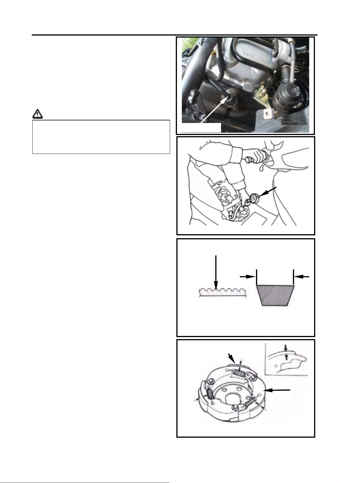
DRIVING SYSTEM
DRIVING BELT
Remove left side cover.
Remove mounting bolt located under air
cleaner.
Remove 9 bolts of the engine left crankcase.
Remove the left crankcase cover.
Check if the belt is crack or worn out.
Replace the belt if necessary or in accord
with the periodical maintenance schedule to
replace it.
Width limit: above 18.5 mm
Clutch pad
Start the motorcycle and gradually increase
throttle valve openness to check clutch pad
operation.
If the motorcycle moves with shaking, then
check its clutch pad for wearing. Replace it
if necessary.
Gear teeth
Width
Clutch pad
Clutch
2-9
Page 31

2. MAINTENANCE INFORMATION SYM
STEERING SYSTEM
Caution
Check all wires and cables if they are
interfered with the rotation of steering
handle bar.
Lift the front wheel out of ground.
Turn handle from right to left and check if
turning is smoothly.
If handle turning is uneven and bending, or
the handle can be operated in vertical
direction, then adjust the handle top bearing.
SUSPENSION SYSTEM
Warning
Do not ride the motorcycle with poor
shock absorber.
Looseness, wear or damage shock
absorber will make poor stability and
driveability.
Front shock absorber
Hold front brake lever and press down the
front shock absorber for several times to
check its operation.
Hold front brake lever and push forward the
front shock absorber for several times to
check its locking status.
Check if it is scratched or leaking.
Replace damaged and non-repairable
components.
Tighten all nuts and bolts.
Rear Shock absorber
Press down the rear shock absorber for
several times to check its operation.
Check if it is scratched or leaking.
Replace damaged and non-repairable
components.
Park the motorcycle with main standard.
Start engine and let the rear wheel rotate
after increased engine rpm. Check engine
for any parts loose or shaking. Also check
the engine suspension bushing for wear out.
Replace the bushing if worn out.
Tighten all nuts and bolts.
Rear Shock absorber
2-10
Page 32

SYM 2. MAINTENANCE INFORMATION
FRONT DISC BRAKE SYSTEM
BRAKE SYSTEM HOSE
Make sure the brake hoses for corrosion or
leaking oil, and also check brake system for
leaking.
BRAKE FLUID
Check brake fluid level in the brake fluid
reservoir. If the level is lower than the
LOWER limit, add brake fluid to UPPER limit.
Also check brake system for leaking if low
brake level found.
Caution
In order to maintain brake fluid in the
reservoir in horizontal position, do not
remove the cap until handle bar stop.
Do not operate the brake lever after the
cap had been removed. Otherwise, the
brake fluid will spread out if operated the
lever.
Do not mix non-compatible brake fluid
together.
FILLING OUT BRAKE FLUID
Tighten the drain valve, and add brake fluid.
Place the diaphragm in.
Operate the brake lever so that brake fluid
contents inside the brake system hoses.
Brake hose
Lower limit
Brake fluid cap
Low brake level
AIR BLEED OPERATION
Connect a transparent hose to draining
valve.
Hold the brake lever and open air bleeding
valve. Perform this operation alternative until
there is no air inside the brake system
hoses.
Caution
Before closing the air bleed valve, do not
release the brake lever.
Bubbles
Draining valve
Transparent hose
2-11
Page 33

2. MAINTENANCE INFORMATION SYM
ADDED BRAKE FLUID
Add brake fluid to UPPER limit lever.
Recommended brake fluid: DOT3 or DOT4
WELL RUN brake fluid.
Caution
Never mix or use dirty brake fluid to prevent
from damage brake system or reducing
brake performance.
BRAKE LINING WEAR
The indent mark on brake lining is the wear
limitation.
Replace the brake lining if the wear limit
mark closed to the edge of brake disc.
Caution
It is not necessary to remove brake hose
when replacing the brake lining.
Brake fluid cap
Low limit
Brake ling wear limit
Remove the brake clipper bolt, and take out
the clipper.
Caution
Do not operate the brake lever after the
clipper removed to avoid clipping the brake
lining.
Pry out the brake lining with a flat driver if
lining be clipped.
Remove brake lining bolt.
Take out the lining.
Caution
In order to maintain brake power balance,
the brake lining must be replaced with one
set.
Brake clipper
Brake
clipper bolt
Brake lining
Brake disc
Bolt
2-12
Page 34

SYM 2. MAINTENANCE INFORMATION
A
A
DRUM BRAKE SYSTEM
Front Brake Free Play: (Drum brake)
Measure free play of rear brake level at the
end of the lever.
Free play: 10-20 mm
Adjust the free play by turning the front brake
adjustment nut if necessary.
10∼20mm
“△” mark
Increasing free
play
Decreasing free play
Adjustment nut
REAR BRAKE FREE PLAY: (DRUM
BRAKE TYPE)
Measure the free play of the front brake lever
at the end of the lever.
Free play: 10-20 mm
Adjust the free play by turning the front brake
adjustment nut if necessary.
BRAKE CONFIRAMTION
Caution
fter brake adjustment, it has to check
the brake operation to make sure the
front and rear wheel can be braked.
Pull the brake lever, and make sure that
the wear limit marks of brake ling on the
both front & rear brake arm are closer
and touch to the “△” marks. If so,
replace the brake ling with new one.
djustment nut
Decreasing
free play
Increasing
free play
“△”marks
2-13
Page 35

2. MAINTENANCE INFORMATION SYM
g
BRAKE LIGHT SWITCH
The brake light switch is to lit up brake light
as brake applied.
Make sure that electrical starter can be
operated only under brake applying.
WHEEL/TIRE
Check if both front and rear tire pressure are
within specification.
Caution
Tire pressure check should be done as cold
tire.
Appointed tire pressure
Tire size Front tire Rear tire
Load for
pressure
as cold tire
(Kg/cm²)
Appointed Tire
Front/Rear wheel: 120/70-12 / 130/70-12
Check if tire surface is ticked with nails,
stones or other materials.
Check if tire surface or wall for crack or
damaged, and replace it if necessary.
The tire tread depth can be checked by
visual inspection or depth gauge.
Replace the tire if tire tread dent or
unusual wearing out.
The tire should be replaced if the wear
limit mark (△) is in visible.
Measure tire thread depth from tire center
surface.
Replace the tire if the depth is not come with
following specification:
Caution
The wear limit marks (△) are located
around the tire wall even for inspection.
single
Load for
two
persons
Front tire: 1.5 mm
Rear tire: 2.0 mm
1.75 2.00 Tire
1.75
2.25
Brake li
Wear limit indictor
ht switch
〝△〞mark
2-14
Page 36

SYM 2. MAINTENANCE INFORMATION
BATTERY
Battery Removal
Remove the 4 screws on the floor panel.
Remove battery cap. (4 screws)
Battery cables removal:
1. At first, remove the negative “-” cable.
2. Then, remove the positive “+” cable.
3. Remove the battery.
If there is some rust on battery posts, clean it
with steel brush.
Install the battery in the reverse procedures
of removal.
Caution
If there is rust on the posts very serious,
spray some hot water on the posts.
Then, clean it with steel brush so that
can remove rust for more easily.
Apply some grease on the posts after
rust removed to prevent from rust again.
Battery cover screws
HEADLIGHT ADJUSTMENT
Remove the front cover.
Turn on the main switch.
Turn the headlight adjustment screw. And
adjust the headlight beam height.
Then, tighten the adjustment screw after the
beam height in proper position.
Caution
To adjust the headlight beam follows
related regulations.
Improper headlight beam adjustment will
make in coming driver dazzled or
insufficient lighting.
NUTS, BOLTS TIGHTENESS
Perform periodical maintenance in accord
with the Periodical Maintenance Schedule.
Check if all bolts and nuts on the frame are
tightened securely.
Check all fixing pins, snap rings, hose (pipe)
clamps, and wire holders for security.
Headlight adjustment screw
2-15
Page 37

SYM 3. LUBRICATION SYSTEM
MECHANISM DIAGRAM....................3-1
OPERATIONAL PRECAUTIONS .......3-2
TROUBLE DIAGNOSIS...................... 3-2
ENGINE OIL.......................................3-3
MECHANISM DIAGRAM
Valve rocker
arm
Scoop lubrication
Connecting rod
Forcedly
lubrication
Crankshaft
CLEANING ENGINE OIL STRAINER...3-3
OIL PUMP............................................3-4
GEAR OIL ............................................3-7
Forcedly lubrication
Camshaft
Inner passage
Oil strainer
Oil pump
3-1
Page 38

3. LUBRICATION SYSTEM SYM
OPERATIONAL PRECAUTIONS
General Information
This chapter contains maintenance operations for the engine oil pump, engine oil and
gear oil.
Specifications
Engine oil quantity Disassembly 850 c.c.
Replacement 750 c.c.
Oil viscosity SAE 10W-30 or equivalent
(Recommended King-Mate
serial oils)
Gear Oil Disassembly 110 c.c.
Replacement 100 c.c.
Oil viscosity of gear oil SAE 85W-140
(Recommended King-Mate
gear oil series SYM
HYPOID GEAR OIL)
Oil viscosity
unit : mm
Items Standard Limit
Inner rotor clearance
Clearance between outer
Oil pump
Torque value
Engine oil drain plug 1.0~1.5kgf-m
Engine oil screen cover 1.0~2.0kgf-m
Gear oil drain bolt 1.0~1.5kgf-m
Gear oil filling bolt 1.0~1.5kgf-m
Oil pump connection screw 0.8~1.2kgf-m
rotor and body
Clearance between rotor
side and body
- 0.12
- 0.12
0.05~0.10 0.20
TROUBLE DIAGNOSIS
Low engine oil level
Oil leaking
Valve guide or seat worn out
Piston ring worn out
Low Oil Pressure
Low engine oil level
Clogged in oil strainer, circuits or pipes
Oil pump damage
Dirty oil
No oil change in periodical
Cylinder head gasket damage
Piston ring worn out
3-2
Page 39

SYM 3. LUBRICATION SYSTEM
Oil
r
ENGINE OIL
Turn off engine, and park the motorcycle in
flat ground with main stand.
Check oil level with oil dipstick after 3-5
minutes.
Do not rotate the dipstick into engine as
checking.
If oil level is nearly low level, fill out
recommended oil to upper level.
Oil Replacement
Caution
Drain oil as engine warmed up so that
make sure oil can be drained smoothly and
completely.
Place an oil pan under the motorcycle, and
remove oil strainer cap.
Make sure if the aluminum washer of the
draining bolt is damaged. If so, replace it
with new one.
Install the drain bolt and tighten it.
Torque value: 3.5~4.5 kgf-m
Dipstick
Oil drain plug
CLEANING ENGINE OIL STRAINER
Remove the oil strainer cap.
Remove oil strainer and spring.
Clean oil strainer (recommended using
compressed air to clean dirty foreign).
Check if the strainer and O-ring of the oil
strainer are broken. Replace with new one if
found.
Install the oil strainer and spring.
Install the oil strainer cap and tighten it.
Torque value: 1.0~2.0 kgf-m
Fill out oil to the oil filler (Oil viscosity SAE
10W-30) (Recommended King-Mate serial
oils).
Engine oil quantity: Replacement 750 c.c.
strainer cap
oil straine
spring
3-3
Page 40

3. LUBRICATION SYSTEM SYM
OIL PUMP
Oil Pump Removal
Remove the alternator (refer to chapter10).
Remove the engine right crankcase cover.
Make sure that the pump axle can be rotated
freely.
Remove the oil pump driving gear nut.
Remove oil pump body bolts (3 bolts).
Remove the oil pump pin.
Remove the oil pump.
Remove the 2 O-rings.
pump driving
gear nut
3bolts
pin
2 O-rings
3-4
Page 41

SYM 3. LUBRICATION SYSTEM
Oil Pump Inspection
Check the clearance between oil pump body
and outer rotor.
Limit: below 0.12 mm
Check clearance between inner and outer
rotors.
Limit: below 0.12 mm
Check clearance between rotor side face
and pump body.
Limit: below 2.0 mm
Oil Pump Re-assembly
Install inner and outer rotors into the pump
body.
Align the indent on driving shaft with that of
inner rotor. Install the driving shaft.
Install the oil pump cover and fixing pin
properly and then tighten screw. (1 screw)
3-5
Page 42

3. LUBRICATION SYSTEM SYM
Oil Pump Installation
Install the 2 O-rings.
Install the oil pump pin.
Install the oil pump.
Install the oil pump body bolts (3 bolts).
Install the oil pump driving gear nut.
Install the alternator (refer to chapter10).
Install the engine right crankcase cover.
2 O-rings
pin
3 bolts
3-6
pump driving
gear nut
Page 43

SYM 3. LUBRICATION SYSTEM
GEAR OIL
Oil Level Inspection
Park the motorcycle on flat ground with main
stand.
Turn off engine and remove both engine oil
filling bolt and oil draining bolt.
Remove gear oil filling hole bolt and place a
measurement cup under the draining plug.
Remove the oil draining plug and the pour
gear oil into the measurement cup.
Measure the gear oil quantity if within
standard value.
Add specified gear oil if the oil level too low.
Standard quantity: 110 cc.
Replacement: 100 cc.
Gear Oil Replacement
Remove the gear oil filling hole bolt and its
draining plug and then drain oil completely.
Install the draining plug and tighten it. (Make
sure if the plug washer is damaged. If so,
replace it with new one.)
Torque Value:1.0~1.5 kgf-m
Add new gear oil (100 c.c.) from the gear oil
filling hole and then install the gear oil filling
hole bolt after added oil. And then, tighten
the bolt.
Torque Value: 1.0~1.5 kgf-m
Filling bolt
Draining bolt
※Recommended to apply with SYM
HYPOID GEAR OIL (SAE 85W-140)
Start engine and run it for 2~3 minutes.
Turn off engine and check if oil leaking.
3-7
Page 44

SYM 4. FUEL SYSTEM
MECHANISM ILLUSTRATION.............4-1
PRECAUTIONS IN OPERATION.........4-2
TROUBLE DIAGNOSIS........................4-3
CARBURETOR REMOVAL..................4-4
VACUUM CHAMBER...........................4-4
AIR CUT-OFF VALVE ..........................4-6
MECHANISM ILLUSTRATION
Fuel strainer
Fuel unit
AUTO BY-STARTER..........................4-7
FLOAT CHAMBER.............................4-8
INSTALLATION OF CARBURETOR..4-9
IDLE SPEED ADJUSTMENT..............4-9
FUEL TANK........................................4-10
AIR CLEANER....................................4-11
Carburetor
Fuel tank cap
4-1
Page 45

4. FUEL SYSTEM SYM
PRECAUTIONS IN OPERATION
General Information
Warning
Gasoline is a low ignition point and explosive materials, so always work in a well-ventilated
place and strictly prohibit flame when working with gasoline.
Cautions
Do not bend or twist throttle valve cable. Damaged cable will make unstable
driveability.
When disassembling fuel system parts, pay attention to O-ring position, replace with
new one as re-assembly
There is a drain screw in the float chamber for draining residual gasoline.
Do not disassemble automatic by-starter and air cut-off valve arbitrarily.
Specification
Item Specification
Main jet 85#
Slow jet 35#
Idle speed 2100±100 rpm
Fuel quantity
adjustment screw
Level in float chamber 3.5±1 mm
Jet needle DA8CD add 2 units 0.5mm washer
Throttle handle free play 2~6 mm
1 1/2±3/4 turns
Torque value
Fuel valve tightening nut: 1.5~2.0 Kgf-m
Tool
Special service tools
Vacuum/air pressure pump
General service tools
Fuel level gauge
4-2
Page 46

SYM 4. FUEL SYSTEM
TROUBLE DIAGNOSIS
Poor engine start
No fuel in fuel tank
Clogged fuel tube
Too much fuel in cylinder
No spark from spark plug (malfunction of
ignition system)
Clogged air cleaner
Malfunction of automatic by-starter
Malfunction of throttle valve operation
Stall after started
Malfunction of automatic by-starter
Incorrect ignition timing
Malfunction of carburetor
Dirty engine oil
Air existing in intake system
Incorrect idle speed
Rough idle
Malfunction of ignition system
Incorrect idle speed
Malfunction of carburetor
Dirty fuel
Intermittently misfire as acceleration
Malfunction of ignition system
Late ignition timing
Malfunction of ignition system
Malfunction of carburetor
Power insufficiency and fuel consuming
Fuel system clogged
Malfunction of ignition system
Mixture too lean
Clogged fuel injector
Vacuum piston stick and closed
Malfunction of float valve
Fuel level too low in float chamber
Clogged fuel tank cap vent
Clogged fuel filter
Obstructed fuel pipe
Clogged air vent hose
Air existing in intake system
Mixture too rich
Clogged air injector
Malfunction of float valve
Fuel level too high in float chamber
Malfunction of automatic by-starter
Dirty air cleaner
4-3
Page 47

4. FUEL SYSTEM SYM
r
r
Carburetor Removal
Remove the luggage box.
Loosen the adjustment nut and fixing nut of
throttle valve cable, and release the cable
from carburetor.
Remove fuel pipe, vacuum hose.
Disconnect auto by-starter connectors.
Release the clamp strip of air cleaner.
Release the clamp strip of carburetor isolator.
Take the carburetor out.
VACUUM CHAMBER
Removal
Loosen drain screw, and drain out residual
fuel in float chamber.
Remove screws (2 screws) of vacuum
chamber cover and the cover.
Remove compress spring and vacuum
piston.
throttle valve cable
auto by-starte
Vacuum Chamber cove
Vacuum piston
vacuum
hose
clamp strip of
isolator
vacuum hose
Screws×2
compress
spring
4-4
Page 48

SYM 4. FUEL SYSTEM
Remove fuel needle seat, spring, and
injector needle.
Check if the vacuum piston for wear out,
crack or other damage.
Check if the diaphragm for damage or crack.
Cautions
Do not damage vacuum diaphragm.
Installation
Install injector needle, spring and fuel needle
seat to vacuum piston.
Cautions
Note direction as installing the piston
set because wrong direction of the
piston cab not be installed.
Align the indent of vacuum
diaphragm with the carburetor body.
Install vacuum piston to carburetor body.
Install compress spring.
Install vacuum chamber cover and tighten 2
screws.
fuel needle
seat
fuel needle
spring
injector
needle
piston
piston diaphragm lock
position
Piston spring
screws×2
4-5
Page 49

4. FUEL SYSTEM SYM
S
2
AIR CUT-OFF VALVE
Removal
Remove the vacuum hose clamp and then
the vacuum hose.
Remove the screws (screw x 2) of the air
cut-off valve and its cover.
Remove the spring and vacuum diaphragm.
Check if the vacuum diaphragm for
deterioration or crack.
Installation
Install the valve as reverse order of removal.
crews ×
screws
vacuum diaphragm
Cautions
Do not damage the vacuum diaphragm
or in opposite installation direction.
4-6
Page 50

SYM 4. FUEL SYSTEM
AUTO BY-STARTER
Inspection
Turn off engine and waiting for over 10
minutes for cooling.
Check resistance across the two terminals of
the auto by-starter
Resistance value: Max. 10Ω (Measured
after engine stopped for more than 10
minutes)
Replace the auto by-starter with a new one if
resistance value exceeds standard.
Remove the carburetor, allow it to cool off for
30 minutes.
Connect a hose to fuel richment circuit.
Pump compressed air to the circuit.
Replace the auto by-starter if the circuit
clogged.
Connect battery posts (12V) to starter’s
connectors. After 5 minutes, test the rich
circuit with compressed air. If air flow
through the circuit, then replace the starter.
Removal
Remove fixing plate screw, and then remove
the plate and auto by-starter from carburetor.
Valve inspection
Check if auto by-starter and valve needle for
damage or wear out.
Installation
Install auto by-starter to the carburetor body.
Install fixing plate to the upper groove of auto
by-starter, and install its flat surface to
carburetor. Install screw and tighten it.
Screws
×2
fixing plate
Screws × 2
automatic
by-starter
round point
Cautions
Align the round point of the starter with
the screw hole of air intake side.
fixing plate
valve needle
4-7
Page 51

4. FUEL SYSTEM SYM
j
j
FLOAT CHAMBER
Disassembly
Remove 4 mounting screws and then the
float chamber cover.
Remove the float pin and float valve.
Checking
Check float needle valve and valve seat for
drop difference damage, wear out, dirty or
clogged.
Cautions
In case of worn out or dirt, the float valve
and valve seat will not tightly close
causing fuel level to increase and as a
result, fuel flooding. A worn out or dirty
float valve must be replaced with a new a
new one.
Remove main jet, fuel needle jet holder, fuel
needle jet, slow jet, fuel amount adjustment
screw.
Cautions
Take care not to damage jets and adjust
screw.
Before removing adjustment screw, turn
it all the way down and note the number
of turns.
Do not turn adjustment screw forcefully
to avoid damaging valve seat face.
Clean jets with cleaning fluid.
Then use compressed air to blow dirt off.
Blow carburetor body passages with
compressed air.
float
float pin
fuel amount
ustment screw
ad
fuel needle jet
float
slow jet
float pin
screws× 4
fuel needle holder
float needle
valve
float pin
main jet
fuel needle
holder
fuel needle
et
main jet
slow jet
4-8
Page 52

SYM 4. FUEL SYSTEM
umber o
r
Installation
Install main jet, fuel needle jet seat, fuel needle jet,
slow speed jet and fuel amount adjustment screw.
Cautions
Set the adjustment screw in according to
n
f turns noted before it was removed.
Install the float valve, float, and float pin.
Checking Fuel Level
Cautions
Check again to ensure float valve, float for
proper installation.
To ensure correct measurement, position
the float meter in such a way so that float
chamber face is vertical to the main jet.
Fuel level: 3.5±1 mm
INSTALLATION OF CARBURETOR
Install carburetor in the reverse order of removal.
Following adjustments must be made after
installation.
Throttle valve cable clearance adjustment
Idle speed adjustment
IDLE SPEED ADJUSTMENT
Caution
Fuel amount adjust screw was set at factory,
so no adjustment is needed. Note the
number of turns it takes to screw it all the
way in for ease of installation.
Never screw in forcedly to avoid damaging
the screw seat.
The main stand must be used to support the
motorcycle to perform the adjustments.
Use a tachometer when adjusting engine RPM.
Screw in adjustment screw gently, then back up to
standard turns.
Standard turns: 1 1/2±3/4 turns
Warm up engine, adjust throttle valve stopper
screw to standard RPM.
Idle speed rpm: 2100±100 rpm
Connect the sampling hose of exhaust analyzer to
exhaust front end. Press test key on the analyzer.
Adjust the air volume adjustment screw and read
CO reading on the analyzer.
CO standard value: 1.0~1.5 %
Accelerate in gradual increments, make sure both
rpm and CO value are in standard values after
engine running in stable. If rpm and CO value
fluctuated, repeat the procedures described above
for adjusting to standard value.
fuel amount
adjustment screw
float mete
throttle valve
stopper screw
Throttle valve cable
adjustment nut
air volume
adjustment screw
4-9
Page 53

4. FUEL SYSTEM SYM
r
FUEL TANK
Fuel unit removal
Remove the seat.
Remove the rear carrier. (3 bolts)
Remove the luggage box assembly (4 bolts).
Disconnect fuel unit connector.
Remove fuel unit.
Cautions
Do not bend the float arm of fuel unit.
Do not fill out too much gasoline to
fuel tank.
Fuel unit inspection. (Refer to chapter 16 electrical equipment).
Fuel unit installation
Install the gauge in the reverse order of
removal.
Cautions
Do not forget to install the gasket of fuel unit
or damage it.
FUEL TANK REMOVAL
Open the seat.
Remove the rear carrier. (3 bolts)
Remove the rear center cover.
Remove the luggage box and the double
seat(4 bolts).
Remove the left & right body cover.
Disconnect the fuel unit connector.
Remove the fuel pipe, fuel filter.
Remove the fuel tank (2 bolts).
fuel unit connecto
fuel unit
gasket
Fuel Tank Installation
Install the tank in the reverse order of
removal.
4-10
Page 54

SYM 4. FUEL SYSTEM
AIR CLEANER
Removal
Remove the seat .
Remove the luggage box assembly (4 bolts).
Loosen the clamp strip of air cleaner.
Remove evaporative return hose.
Remove the air cleaner body bolts (2 bolts).
Remove the air cleaner.
air filter strap
Installation
Install the air cleaner in the reverse order of
removal.
Air Cleaner Element Cleaning
Remove the air cleaner cover (7 screws).
Remove the air cleaner element (2 screws).
With compressed air to clean dirty around
the element. Replace it if it is too dirty to
clean.
bolts×2
screws×7
Cautions
The air cleaner element is made of
paper so do not soap it into water or
wash it with water.
Air cleaner element
4-11
Page 55

SYM 5. REMOVAL OF ENGINE
MECHANISM DIAGRAM......................5-1
OPERATIONAL PRECAUTIONS .........5-2
ENGINE REMOVAL .............................5-3
MECHANISM DIAGRAM
4.5~5.5kgf-m
REMOVAL OF ENGINE SUSPENSION BUSHING .5-6
ENGINE SUSPENSION FRAME..........5-7
INSTALLATION OF ENGINE............... 5-8
3.5~4.5kgf-m
4.5~5.5kgf-m
2.4~3.0kgf-m
4.5~5.5 kgf-m
5-1
Page 56

5. REMOVAL OF ENGINE SYM
OPERATIONAL PRECAUTIONS
General Information
Engine must be supported by a bracket or adjustable tool in height.
The following parts can be serviced with the engine installed on the frame.
1. Carburetor
2. Driving disk, driving belt, clutch, and transporting disk
3. Final reduction gear mechanism
Specification
Disassemble 800 c.c.
Engine Oil Capacity
Replacement 750 c.c.
Disassemble 110 c.c.
Gear Oil Capacity
Replacement 100 c.c.
Torque Values
Engine suspension bolt (frame side) 4.5~5.5kgf-m
Engine suspension nut (engine side) 4.5~5.5kgf-m
Bolt of rear shock absorber upper connection 3.5~4.5kgf-m
Bolt of rear shock absorber lower connection 2.4~3.0kgf-m
Specification
5-2
Page 57

SYM 5. REMOVAL OF ENGINE
G
r
ENGINE REMOVAL
Open the seat.
Remove the luggage box assembly (4
bolts ).
Remove the body cover .
Remove the power connector of auto bystart.
Remove the generator wire and pulse
generator connector.
Remove the starter motor wire on the Starter
magnetic switch.
Remove the spark plug.
enerato
connector
pulse generator
connector
Auto by-start
connector
Starter magnetic switch
Spark plug
5-3
Page 58

5. REMOVAL OF ENGINE SYM
Remove the fuel pipe, vacuum hose, and
throttle valve cable from the carburetor.
Loose the strap screw of the air cleaner
guide, and then the air cleaner guide.
Remove the exhaust muffler (Bolts ×
2, Nuts × 2).
Remove the rear wheel (Nut × 1).
Remove the air cleaner connection bolts (2
bolts).
Bolts×2
Nut ×1
2 bolts
5-4
Page 59

SYM 5. REMOVAL OF ENGINE
Remove the rear brake cable nut.
Remove the rear brake cable.
Remove the rear shock absorber lower bolt.
Loose the strap screw of engine left guide,
and then remove the engine left guide.
Brake cable nut
Rear shock
absorber bolt
Strap screw of guide
Remove the engine suspension nut and bolt
(engine side), and then remove the engine.
Caution
With a bracket to support the engine
to prevent from it damage by falling
down as removing the engine.
Check if the engine suspension, rear shock
absorber bushing, and cushion rubber for
damage. Replace them with new ones if so.
Engine suspension bolt/nut
Bushing
5-5
Page 60

5. REMOVAL OF ENGINE SYM
REMOVAL OF ENGINE
SUSPENSION BUSHING
If engine suspension frame and the cushion
rubber of rear shock absorber bushing
damaged. Then, with the bushing remover /
presser, Φ28mm &Φ20mm, to press the
bushing out, and replace it with new one.
Engine suspension bushing: Φ28mm
Rear shock absorber bushing: Φ20mm
Pressing out
Place the detent section of the bushing
remover toward the bushing, and drive both
the pressing ring and bolt in to press the
bushing out.
Pressing In
Place the flat section of the remover toward
the bushing, and then drive the bushing,
pressing ring, and bolt in to install the
bushing.
5-6
Page 61

SYM 5. REMOVAL OF ENGINE
ENGINE SUSPENSION FRAME
Removal
Remove the right side bolt of engine
suspension frame.
Remove the left side bolt of engine
suspension frame.
Check if the engine suspension frame
bushing and cushion rubber for damage. If
so, replace with new ones.
Installation
Tighten the bolts and nuts of engine
suspension frame.
Engine suspension frame nut:
Torque Value: 4.5~5.5 kgf-m
Bolt of engine suspension
frame (left side)
5-7
Page 62

5. REMOVAL OF ENGINE SYM
INSTALLATION OF ENGINE
Check if the bushings of engine suspension
frame and shock absorber for damaged. If so,
replace with new ones.
Install the engine according to the reversing
order of removal.
Caution
Notice both feet and hands safety for
squeezing as engine installation.
Do not bent or squeeze each wires or
hose.
Route all cables and wires in
accordance with the routine layout.
Engine suspension nut:
Torque Value: 4.5~5.5kgf-m
Rear shock absorber bolt:
Torque Value: Top: 3.5~4.5kgf-m
lower: 2.4~3.0kgf-m
Engine suspension nut×1
Brake cable nut
Rear wheel axle nut:
Torque Value: 11.0~13.0kgf-m
Rear shock
absorber lower bolt
Rear wheel axle nut×1
5-8
Page 63

SYM 6. CYLINDER HEAD/VALVE
MECHANISM DIAGRAM....................6-1
PRECAUTIONS IN OPERATION.......6-2
TROUBLE SHOOTING.......................6-3
CAMSHAFT REMOVAL .....................6-4
CYLINDER HEAD REMOVAL............6-6
CYLINDER HEAD DISASSEMBLY ....6-7
MECHANISM DIAGRAM
0.8~1.2 kgf-m
CYLINDER HEAD INSPECTION..........6-8
VALVE SEAT INSPECTION AND SERVICE
CYLINDER HEAD REASSEMBLY.......6-12
CYLINDER HEAD INSTALLATION......6-13
CAMSHAFT INSTALLATION ...............6-13
VALVE CLEARANCE ADJUSTMENT..6-14
0.7~1.1 kgf-m
6-10
1.0~1.4 kgf-m
1.0~1.4 kgf-m
0.8~1.2 kgf-m
6-1
Page 64

6. CYLINDER HEAD/VALVE SYM
PRECAUTIONS IN OPERATION
General Information
This chapter is contained maintenance and service for cylinder head, valve, and camshaft
as well as valve rocker arm.
Cylinder head service cannot be carried out when engine is in frame.
Specification unit: mm
Item Standard Limit
Compression pressure 12 kg/cm²
Intake 25.686~25.786 25.29
Camshaft Height of cam lobe
Exhaust 25.50~25.60 25.12
Rocker
arm
OD of valve stem
Valve
Torque Value
Cylinder head cover bolt 0.8~1.2kgf-m
Cylinder head bolt (LH) 0.8~1.2kgf-m
Sealing bolt of timing chain auto-adjuster 0.8~1.2kgf-m
Bolt of timing chain auto-adjuster 1.0~1.4kgf-m
Timing gear cover bolts
Spark plug 1.0~1.4kgf-m
Cam holder nut 0.8~1.2kgf-m
Valve adjustment fixing nuts 0.7~1.1kgf-m
TOOLS
Clearance between
valve stem and guide
Free length of valve
ID of valve rocker arm 10.000~10.015 10.10
OD of valve rocker arm shaft 9.972~9.987 9.910
Intake 4.975~4.99 4.90
Exhaust 4.955~4.97 4.90
OD of Guide 5.00 5.030
Intake 0.010~0.037 0.080
Exhaust 0.030~0.057 0.100
Outer 35.25
spring
Inner 32.26~32.56
0.7~1.1kgf-m (apply with oil on bolt thread & seat)
-
-
-
Special service tools
Valve reamer: 5.0mm
Valve guide driver: 5.0mm
Valve spring compressor
6-2
Page 65

SYM 6. CYLINDER HEAD/VALVE
TROUBLE SHOOTING
Engine performance will be effected by troubles on engine top end. The troubles usually can
be determinate or by performing cylinder compression test and judging the abnormal noise
generated.
Rough Idle
Low compression pressure.
Low compression pressure
1. Valve
Improper valve adjustment.
Burnt or bended valve.
Improper valve timing.
Valve spring damaged.
Valve carbon.
Poor sealing on valve seat.
Improper spark plug installation.
2. Cylinder head
Cylinder head gasket leaking or damage.
Tilt or crack cylinder surface.
3. Piston
Piston ring worn out.
High compression pressure
Too much carbon deposit on combustion chamber or piston head.
Noise
Improper valve clearance adjustment
Burnt valve or damaged valve spring
Camshaft wear out or damage
Cam chain wear out or looseness
Auto-adjuster wear out or damage of cam chain
Camshaft sprocket wear out
Rocker arm or rocker arm shaft wear out
White smoke
Valve guide or valve stem wear out
Valve stem seal wear out
6-3
Page 66

6. CYLINDER HEAD/VALVE SYM
CAMSHAFT REMOVAL
Remove the shroud of the engine.
Remove the crankcase blow-by system hose
from the cylinder head.
Remove the cylinder head bolts and then
remove the cylinder head (4 bolts).
Loosen the screw of camshaft chain adjuster
and remove O-ring.
With a flat screwdriver to tighten the screw of
camshaft chain adjuster in a clockwise
motion for release adjuster.
Turn the flywheel in counter clockwise
motion with T type wrench until the “T” mark
on flywheel aligned with the mark on the
crankcase so that the hole on the camshaft
sprocket is forward up and piston is at TDC
position.
Remove camshaft holder nut and washer.
Blow-by hose
A.I.
camshaft chain adjuster
4 bolts
screw
Hole
TDC mark
Caution
Loosen the nuts diagonally by 2-3
sequences.
6-4
4 nuts
Page 67

SYM 6. CYLINDER HEAD/VALVE
g
Remove the camshaft holder and rocker arm
set.
Remove the camshaft chain from the
camshaft sprocket.
Remove the camshaft.
Camshaft Inspection
Inspect cam lobe height for damaged.
Service Limit
IN: Replacement when less than 25.29 mm
EX: Replacement when less than 25.12 mm
Inspect the camshaft bearing for looseness
or wear out. If any, replace whole set of
camshaft and bearing.
Disassembly Of Camshaft Holder
With a 5 mm bolt to screw in the cam rocker
arm shaft so that take it out.
Remove cam rocker arm.
Inspection Of Camshaft Holder
Check if the camshaft holder, cam rocker
arm and rock arm shaft for wearing out or
damage.
Camshaft
bearin
5mm bolt
rocker arm
shaft
rocker arm
Caution
Further check is necessary if any wear
is found on the moveable surface of
cam rocker arm.
Check if the camshaft bearing mounting
surface for wear or damage.
Measure the cam rocker arm I.D. of the
camshaft holder.
Service Limit: Replace when it is above
12.10 mm
rocker arm
shaft
6-5
Page 68

6. CYLINDER HEAD/VALVE SYM
A
Measure the valve rocker arm I.D.
Service Limit: Replace when it is above
10.100 mm
Measure the active O.D. of the valve rocker
arm shaft and valve rocker arm.
Service Limit: Replace when it is above
9.910 mm
Calculate the clearance between the rocker
arm shaft and the rocker arm.
Service Limit: Replace when it is above
0.10 mm
CYLINDER HEAD REMOVAL
Remove double seat, luggage box and front
center cover.
Remove the engine (refer to Chapter 5).
Remove the cooling fan cover.
Remove the engine shroud (4 bolts).
Remove the camshaft.
Blow-by hose
.I
4 bolts
6-6
Page 69

SYM 6. CYLINDER HEAD/VALVE
Remove the 2 cylinder head mounting bolts
from cylinder head left side cover.
Remove cylinder head gasket and 2 dowel
pins.
Remove chain plate.
Clean up residues from the matching
surfaces of cylinder and cylinder head.
Caution
Do not damage the matching surfaces of
cylinder and cylinder head.
Avoid residues of gasket or foreign
materials falling into crankcase as
cleaning.
CYLINDER HEAD DISASSEMBLY
Use a valve compressor to press the valve
spring.
After removed valve cotters, release the
compressor and then take out spring retainer,
valve spring and valves.
dowel pins
Chain plate
Cylinder head gasket
valve cotters
Caution
In order to avoid to loosing spring
tension, do not compress the spring too
much. Its length is based on the
installation of latch.
Special Service Tool: Valve spring compressor.
Remove valve stem guide seal.
Clean carbon deposits in combustion chamber.
Clean residues and foreign materials on
cylinder head matching surface.
Caution
Do not damage the matching surface of
cylinder head.
6-7
Page 70

6. CYLINDER HEAD/VALVE SYM
p
CYLINDER HEAD INSPECTION
Check if spark plug and valve holes are crack.
Measure cylinder head flat with a
straightedge and flat feeler gauge.
Service limit: 0.5mm
Valve spring free length
Measure the free length of intake and
exhaust valve springs.
Standard
Outer : 35.250 mm
Inner : 32.410 mm
Valve stem
Check if valve stems are bend, crack or burn.
Check the operation condition of valve stem
in valve guide, and measure & record the
valve stem outer diameter.
Service Limit: IN→ 4.900mm
EX→ 4.900mm
Valve guide
The narrow pitch of the spring shall face to the
combustion chamber.
Caution
Before measuring the valve guide, clean
carbon de
Special Service Tool: 5.0mm valve guide
reamer
Measure and record each valve guide inner
diameters.
Service limit: 5.030mm
The difference that the inner diameter of
valve guide deducts the outer diameter of
valve stem is the clearance between the
valve stem and valve guide.
Service Limit: IN→ 0.08mm
EX→ 0.10mm
osits with reamer.
6-8
5.0mm valve guide reamer
Page 71

SYM 6. CYLINDER HEAD/VALVE
V
r
V
r
Caution
If clearance between valve stem and valve
guide exceeded service limit, check whether
the new clearance that only replaces new
valve guide is within service limit or not. If
so, replace valve guide.
Correct it with reamer after replacement.
If clearance still exceeds service limit after
replaced valve guide, replace valve stem too.
Caution
It must correct valve seat when replacing
valve guide.
Valve guide replacement
Heat up cylinder head to 100~150 ℃ with
heated plate or toaster.
Caution
Do not let torch heat cylinder head directly.
Otherwise, the cylinder head may be
deformed as heating it.
Wear on a pair of glove to protect your
hands when operating.
Hold the cylinder head, and then press out old
valve guide from combustion chamber side.
Tool: Valve guide driver 5 mm
Caution
Check if new valve guide is deformation
after pressed it in.
When pressing in the new valve guide,
cylinder head still must be kept in 100~150
℃.
alve guide drive
5.0mm
13 mm
(0.15in)
alve guide drive
5.0mm
Adjust the valve guide driver and let valve
guide height is in 13mm.
Press in new valve guide from rocker arm side.
Tool: Valve guide driver 5 mm
Wait for the cylinder head cooling down to
room temperature, and then correct the new
valve guide with reamer.
Caution
Using cutting oil when correcting valve
guide with a reamer.
Turn the reamer in same direction when it
be inserted or rotated.
Correct valve seat, and clean up all metal
residues from cylinder head.
Special tool: Valve guide reamer 5 mm
Valve guide reamer 5.0mm
6-9
Page 72

6. CYLINDER HEAD/VALVE SYM
V
VALVE SEAT INSPECTION AND
SERVICE
Clean up all carbon deposits onto intake and
exhaust valves.
Apply with emery slightly onto valve contact
face. Grind valve seat with a rubber hose or
other manual grinding tool.
Caution
Do not let emery enter into between valve
stem and valve guide.
Clean up the emery after corrected, and
apply with red paint onto contact faces of
valve and valve seat.
Remove the valve and check its contact
face.
Caution
Replace the valve with new one if valve
seat is roughness, wear out, or incomplete
contacted with valve seat.
If the valve and the valve seat still can not
be matched sealing after grinded, replace it
with new one.
Valve seat inspection
If the valve seat is too width, narrow or rough,
correct it.
Valve seat width
Service limit: 1.6mm
Check the contact condition of valve seat.
Valve seat grinding
The worn valve seat has to be grinded with
valve seat chamfer cutter.
Use 45° valve seat chamfer cutter to cut any
rough or uneven surface from valve seat.
Roughness
45°
alve seat
valve seat
width
width
Caution
After valve guide had been replaced, it
has to be grinded with 45° valve seal
chamfer cutter to correct its seat face.
Old valve seat width
32°
Use 32° cutter to cut a quarter upper part
out.
6-10
Page 73

SYM 6. CYLINDER HEAD/VALVE
Use 60° cutter to cut a quarter lower part out.
Remove the cutter and check new valve
seat.
Use 45° cutter to grind the valve seat to
specified width.
Caution
Make sure that all roughness and
uneven faces had been grinded.
Grind valve seat again if necessary.
Coat the valve seat surface with red paint.
Install the valve through valve guide until the
valve contacting with valve seat, slightly
press down the valve but do not rotate it so
that a seal track will be created on contact
surface.
Contact surface too high
Old valve seat width
60°
1.0mm
45°
Old valve seat
width
Caution
The contact surfaces of valve and valve
seat are very important to the valve
sealing capacity.
If the contact surface too high, grind the
valve seat with 32° cutter.
Then, grind the valve seat with 45° cutter to
specified width.
If the contact surface too low, grind the valve
seat with 60° cutter.
Then, grind the valve seat with 45° cutter to
specified width.
Contact surface
too low
32°
Old valve seat
width
60°
6-11
Page 74

6. CYLINDER HEAD/VALVE SYM
V
V
After the valve seat grinded, coat valve seat
surface with emery and then slightly press
the grinded surface.
Clean up all emery coated onto cylinder and
valve after grinded.
CYLINDER HEAD REASSEMBLY
Lubricate valve stem with engine oil, and
then insert the valve into valve guide.
Install new valve stem oil seal.
Install valve springs and retainers.
Valve cotters
alve spring
retainer
alve stem
oil seal
Caution
The closed coils of valve spring should
face down to combustion chamber.
Use valve spring compressor to press valve
spring.
Install valve split locks and release the valve
compressor.
Caution
In order to avoid to loosing spring
tension, do not compress the spring too
much. Its length is based on the
installation of latch.
Special tool: valve spring compressor
Tap valve stem to make valve retainer and
valve stem sealing properly.
Valve spring
Valve
Caution
Place and hold cylinder head on to working
table so that can prevent from valve
damaged.
6-12
Page 75

SYM 6. CYLINDER HEAD/VALVE
CYLINDER HEAD INSTALLATION
Install the lock pins and new cylinder head
gasket onto the cylinder head.
Install the camshaft chain plate.
Install the cylinder head.
Lock pins
Cylinder head gasket
Chain plate
CAMSHAFT INSTALLATION
Assemble the camshaft holder.
Install the exhaust valve rocker arm set onto
the camshaft holder showing “EX” mark.
Install intake valve rocker arm and rocker
arm shaft.
Caution
The tangent of rocker shaft of intake
valve should match with the bolt hole of
camshaft mounting seat.
With T type wrench to turn crankshaft in a
clockwise motion so that the “T” mark on the
flywheel aligns with the mark on crankcase.
(piston is at TDC position)
Place the TDC marks of the cam sprocket at
same level of the top-end of cylinder head.
The other single hole of the cam sprocket is
in upward. Then, install the cam chain onto
the cam sprocket.
5mm blot
Camshaft
Rocker
arm shaft
Rocker arm
Cam chain
6-13
Page 76

6. CYLINDER HEAD/VALVE SYM
A
A
Install the lock pins.
Install the camshaft holder, gasket and nut
onto the cylinder head.
Tighten the cylinder head nuts. (4 nuts)
At first, tighten the 4 nuts on the cylinder top
and then tighten the 2 bolts on the left side of
cylinder head.
Torque value: 1.8~2.2 kgf-m
Install the spark plug and tighten it.
Torque value: 1.0~1.4 kgf-m
Caution
pply with oil onto the thread of cylinder
head bolts and tighten the bolts in
diagonally for 2-3 sequences.
Do not over tightening the bolts to avoid
the cylinder head deformation, noise
created or leaking so that effects
motorcycle’s performance.
VALVE CLEARANCE ADJUSTMENT
Loosen valve clearance adjustment nuts and
bolts located on valve rocker arm.
Measure and adjust valve clearance with
feeler gauge.
After valve clearance had been adjusted to
standard value, hold adjustment bolt and
then tighten the adjustment nut.
Standard Value: IN/EX 0.03/0.05±0.02mm
With flat screwdriver, turn the cam sprocket
adjuster in counter-clockwise motion so that
the adjuster is pushed out to contact the cam
chain plate tightly. Apply with oil onto a new
O-ring and then install it onto the adjuster
hole. Tighten the bolt cap of the adjuster
adjustment hole.
pin
holder
Especial tool
Caution
The O-ring must be installed into glove.
Replace the O-ring of the cylinder head with
new one. Install the cylinder head.
Tighten the cylinder head lock bolts.
Connect the blow-by hose onto the cylinder
head.
Tighten the 2nd air injection (AI) nut.
Install the engine onto the engine frame.
(Refer to Chapter 5)
6-14
Blow-by hose
.I
4 bolts
Page 77

SYM 7. CYLINDER/PISTON
MECHANISM DIAGRAM....................7-1
PRECAUTIONS IN OPERATION.......7-2
TROUBLE DIAGNOSIS...................... 7-2
CYLINDER REMOVAL.......................7-3
MECHANISM DIAGRAM
PISTON REMOVAL............................7-5
PISTON RING INSTALLATION ..........7-7
PISTON INSTALLATION....................7-8
CYLINDER INSTALLATION.............. 7-8
0.8~1.2kgf-m
7-1
Page 78

7. CYLINDER/PISTON SYM
PRECAUTIONS IN OPERATION
General Information
Both cylinder and piston service cannot be carried out when engine mounted on frame.
Specification unit: mm
Item Standard Limit
ID 39.00 Bend/wrap age
Cylinder
Roundness 0.005 0.050
Cylindrical 0.005 0.050
Clearance between
piston rings
Piston/
Piston ring
OD of piston pin 12.994~13.000 12.980
Ring-end gap
OD of piston 38.970~38.990 Clearance between piston and
cylinder
ID of piston pin hole 13.002~13.008 13.040
Top ring 0.025~0.060 0.090
2nd ring 0.015~0.050 0.090
Top ring 0.200~0.400 0.500
2nd ring 0.250~0.400 0.650
Oil ring
-
0.200~0.700 -
0.025~0.040 0.100
0.050
Clearance between piston and piston pin 0.002~0.014 0.060
ID of connecting rod small-end 13.005~13.020 13.040
TROUBLE DIAGNOSIS
Low Or Unstable Compression Pressure
Cylinder or piston ring worn out.
Compress pressure to high.
Too much carbon deposited in combustion
chamber and piston.
Knock or Noise
Cylinder or piston ring worn out.
Carbon deposits on cylinder head top-side.
Piston pin hole and piston pin wear out.
Smoking in Exhaust Pipe
Piston or piston ring worn out.
Piston ring installation improperly.
Cylinder or piston damage.
Engine Overheat
Carbon deposits on cylinder head top side.
7-2
Page 79

SYM 7. CYLINDER/PISTON
C
C
CYLINDER REMOVAL
Remove cylinder head. (refer to chapter 6)
Remove 2 bolts and then take out the cam
chain auto-adjuster.
Remove cam chain plate.
Remove cylinder.
Remove cylinder gasket and lock pins
Clean the residues attached onto the
matching surfaces of cylinder and
crankcase.
Cylinder
am chain
guide
2 bolts
am chain
auto-adjuster
7-3
Page 80

7. CYLINDER/PISTON SYM
I
Cover the holes of crankcase and cam chain
with a piece of cleaning cloth.
Clean up all residues or foreign materials
from the two matching surfaces of cylinder
and crankcase.
Caution
To soap the residues into solvent so that
the residues can be removed more easily.
INSPECTION
Check if the inner diameter of cylinder is
worn out or damaged.
In the 3 positions (top, center and bottom)
of cylinder, measure the X and Y direction
values respective in the cylinder.
Service limit:41.00mm
Calculate both the real roundness (the
difference between X and Y motion values)
and the cylindrical roundness (the
difference in the top, center or bottom
positions of X or Y motion values.). Then,
determinate by the max. value.
Service limit
Real roundness: correct or replace as
over 0.05 mm
Cylindrical roundness: correct or replace
as over 0.05 mm
Check Cylinder flat.
Service limit: correct or replace as over
0.05 mm
Exhaust side
Top
Center
Bottom
ntake side
7-4
Page 81

SYM 7. CYLINDER/PISTON
PISTON REMOVAL
Plug crankcase opening with a cleaning cloth
to prevent from piston pin snap ring or other
parts falling into crankcase when
disassembling.
Hold another snap ring with pliers.
Push out the piston pin from the side that not
removed the snap ring.
Remove piston rings.
Caution
Pay attention to remove piston rings
because they are fragile.
Disassemble the piston rings.
Check if the piston rings are damaged or its
grooves are worn.
Cleaning the carbon in piston ring grooves.
Install the piston rings and then measure
clearance between piston ring and its
grooves.
Service Limit: Top ring: replace if over
0.09mm
2nd ring: replace if over
0.09mm
Take out the piston rings and place them
respective into cylinder below 20mm of
cylinder top. Measure each piston ring
gaps.
Piston
Piston ring
Push in
Feeler gauge
Feeler gauge
Caution
Push the piston rings into cylinder with
piston top-end in parallel motion.
Service Limit: Top ring: replace if over
0.50mm
2nd ring: replace if over
0.650mm
piston ring
7-5
Page 82

7. CYLINDER/PISTON SYM
Th
iti
Measure the outer diameter of piston pin.
Service Limit: 12.980mm
Measure the inner diameter of connecting
rod small end.
Service Limit: 13.020mm
Measure the inner diameter of piston pin
hole.
Service Limit: 13.040mm
Calculate clearance between piston pin and
its hole.
Service Limit: 0.02mm
Measure piston outer diameter.
Caution
e measurement pos
distance from piston bottom side, and 90°
to piston pin.
Service limit: 38.970mm
Compare measured value with service limit
to calculate the clearance between piston
and cylinder.
on is 10 mm
7-6
Page 83

SYM 7. CYLINDER/PISTON
PISTON RING INSTALLATION
Clean up piston top, ring groove, and piston shirt.
Install the piston ring onto piston carefully.
Place the openings of piston ring as diagram shown.
Caution
Do not damage piston and piston rings as installation.
All marks on the piston rings must be forwarded to up side.
Make sure that all piston rings can be rotated freely after installed.
120°
Top groove
Over 20 mm
Top ring
2nd ring
Side ring
Spacer
Side ring
Oil ring
2nd groove
Oil groove
7-7
Page 84

7. CYLINDER/PISTON SYM
PISTON INSTALLATION
Install piston and piston pin, and place the IN
mark on the piston top side forward to intake
valve.
Install new piston pin snap ring.
Caution
Do not let the opening of piston pin snap
ring align with the opening piston ring.
Place a piece of cleaning cloth between
piston skirt section and crankcase in
order to prevent snap ring from falling
into crankcase as operation.
CYLINDER INSTALLATION
Clean up all residues and foreign materials
on the matching surface of crankcase.
Pay attention to not let these residues and
foreign materials fall into crankcase.
Piston pin
IN mark
Piston
Caution
To soap the residues into solvent so that
the residues can be removed more
easily.
Install 2 lock pins and new gasket.
Coat engine oil to inside of cylinder, piston
and piston rings.
Care to be taken when installing piston into
cylinder. Press piston rings in one by one as
installation.
Caution
Do not push piston into cylinder forcefully
because this will cause the piston and the
piston rings to be damaged.
Install the cam chain plate, the cylinder
gasket and lock pins.
Install cylinder head. (refer to Chapter 6)
Install the cam chain auto-adjuster. (2 bolts)
7-8
2 bolts
Page 85

SYM 8. V-BELT DRIVING SYSTEM/KICK STARTER ARM
MECHANISM DIAGRAM....................8-1
MAINTENANCE DESCRIPTION........8-2
TROUBLE DIAGNOSIS...................... 8-2
LEFT CRANKCASE COVER..............8-3
MECHANISM DIAGRAM
5.0~6.0kgf-m
KICK STARTER ARM ........................8-3
DRIVING BELT...................................8-4
SLIDING PULLEY ..............................8-6
CLUTCH/DRIVEN PULLEY............... 8-9
0.8~1.2kgf-m
5.0~6.0kgf-m
3.5~4.5kgf-m
8-1
Page 86

8. V-BELT DRIVING SYSTEM/KICK STARTER ARM SYM
MAINTENANCE DESCRIPTION
PRECAUTIONS IN OPERATION
GENERAL INFORMATION
• Driving pulley, clutch, and driven pulley can be serviced on the motorcycle.
• Driving belt and driving pulley surface must be free of grease.
Specification Unit: mm
Item Standard value Limit
Driving belt width
ID of sliding pulley bushing
17.50
20.035~20.085
16.8
20.150
OD of sliding pulley hub
OD of roller
ID of clutch outer
Thickness of clutch lining
Free length of driving pulley
spring
OD of driving pulley
ID of sliding pulley
ID: Inner Diameter
OD: Outer diameter
Torque value
Sliding pulley nut: 5.0~6.0kgf-m
Clutch outer nut: 5.0~6.0kgf-m
driving pulley nut: 3.5~4.5kgf-m
TROUBLE DIAGNOSIS
Engine can be started but motorcycle
can not be moved
1. Worn driving Belt
2. Worn tilt plate
3. Worn or damaged clutch lining
4. Broken driven pulley
Shudder or misfire when driving
1. Broken clutch lining
2. Worn clutch lining
20.01~20.025 19.980
15.920~16.080 15.570
107.00~107.20 107.50
4.000 3.10
97.20 90
33.965~33.985 33.940
34.000~34.025 34.060
Special Service Tools
Clutch spring compressor
Bearing puller (inner type)
Clutch mounting nut wrench
Universal fixture
Insufficient horsepower or poor high
speed performance
1. Worn driving belt
2. Insufficient spring capacity of driven
pulley
3. Worn roller
4. Driven pulley operation un-smoothly
8-2
Page 87

SYM 8. V-BELT DRIVING SYSTEM/KICK STARTER ARM
LEFT CRANKCASE COVER
Left crankcase cover removal
Remove air cleaner. (2 bolts)
Remove kick starter arm. (1 bolt)
Loosen vent strap on the front-left side of
cover, and then remove the vent.
Remove engine left-side cover (8 bolts).
KICK STARTER ARM
Disassembly
Remove the return spring, starter shaft.
Remove driving gear, friction spring and
washer.
Inspection
Check if starter shaft, driving gear, for wear
or damage. Replace it with new one if
necessary.
Check the return spring for spring force or
damaged. Replace it with one if poor parts
found.
Reassembly
Apply with some specified grease on the
gear, shaft.
Install the friction spring of driving gear onto
convex part of the case cover.
Install, return spring and starter shaft as
diagram shown.
Install kick starter arm temporary.
Rotate the lever and then align driving gear
with width-tooth on the starter shaft.
Install thrust washer and socket onto starter
shaft.
Installation of the left crankcase
cover
Install the left crankcase cover. (8 bolts)
Install front vent tube of left cover and tighten
the strap.
Install kick starter arm. (1 bolt)
Tighten the air cleaner. (2 bolts)
air cleaner lock nut
kick starter arm
Starter shaft
Friction spring
Starter shaft
Driving gear
Return spring
starter shaft gear
driving gear
Strap Bolts
Kick starter arm shaft
8-3
Page 88

8. V-BELT DRIVING SYSTEM/KICK STARTER ARM SYM
r
DRIVING BELT
Removal
Remove left crankcase cover.
Hold the sliding pulley with a universal fixture,
and then remove the nut and sliding pulley.
Hold driving pulley with universal fixture, and
remove nut and clutch outer.
Caution
Using special service tools for tightening or
loosening the nut. Fixed rear wheel or rear
brake only will damage reduction gear
system.
Push the driving belt into belt groove as
diagram shown so that the belt can be
loosened, and then remove.
Driving belt and clutch at same time.
Inspection
Check the driving belt for crack or wear.
Replace it if necessary.
Measure the width of driving belt as diagram
shown. Replace the driving belt if it exceed
maintenance limited specification.
Service Limit: 16.80mm
Caution
Using the genuine parts for replacement.
The surfaces of driving belt or pulley must
be free of grease.
Clean up all grease or dirt before
installation.
sliding pulley
driving pulley
Tooth
Driving belt
Universal fixer
Universal fixe
Width
Nut
8-4
Page 89

SYM 8. V-BELT DRIVING SYSTEM/KICK STARTER ARM
Installation
Pull out the driving pulley and then insert the
driving pulley.
Caution
Pull out driving pulley and then insert the
driving belt into the driving pulley so that the
driving belt set can be installed onto sliding
pulley more easily.
Install the starter gear.
Install the clutch set with driving belt onto the
driving shaft.
Install the sliding pulley on the other end of
belt.
Install clutch outer.
Sliding
driven
pulley
starter gear
Install the clutch with universal fixture, and
then tighten nut to specified torque value.
Torque value: 3.5~4.5 kgf-m
Caution
When install the driving belt, if there is a
arrow mark, then the arrow mark must
point to rotation motion. If not, the letters
on the belt must be forwarded to
assembly direction.
sliding pulley
Nut
clutch outer
Clutch outer
Universal fixer
8-5
Page 90

8. V-BELT DRIVING SYSTEM/KICK STARTER ARM SYM
SLIDING PULLEY
REMOVAL
Remove left crankcase cover.
Hold driving pulley with universal fixture, and
then remove driving pulley nut.
Remove driving pulley.
Remove the driving belt from the pulley.
Remove sliding pulley set and driving pulley
hub from crankshaft.
Remove the belt and the starter gear.
Starter gear
driving pulley
nut
Sliding pulley
Remove tilt plate.
Remove weight rollers from sliding pulley.
Crankshaft
Tilt plate
Sliding pulley
Driving pulley hub
8-6
Roller
Page 91

SYM 8. V-BELT DRIVING SYSTEM/KICK STARTER ARM
Inspection
The operation of sliding pulley is means of
the weight roller to pressing on it with
centrifuge force. And then the speed is
changed by the title plate rotation. Thus, if
weight rollers are wear out or damage, the
centrifuge force will be effected.
Check if rollers are wear out or damage.
Replace it if necessary.
Measure each rollers’ outer diameter.
Replace it if exceed the service limit.
Service limit: 15.570 mm
Check the pulley hub if damaged or wear out.
Replace it if necessary.
Measure the pulley hub’s outer diameter.
Replace it if exceed the service limit.
Service limit: 19.980 mm
Measure the pulley hub’s inner diameter.
Replace it if exceed the service limit.
Service limit: 20.150 mm
Weight roller
Sliding pulley
Pulley hub
Assembly/Installation
Install the weight rollers.
Install the title plate guide boot onto the title
plate.
Install the title plate.
Weight roller
Guide boot
Tilt plate
8-7
Page 92

8. V-BELT DRIVING SYSTEM/KICK STARTER ARM SYM
Apply with grease 4~5 g to inside of driving
shaft hole, and install driving pulley hub.
Caution
The pulley surface has to be free of
grease. Clean it with cleaning solvent.
Install siding pulley assembly onto crankshaft.
Sliding pulley
Crankshaft
Pulley surface
Pulley hub
DRIVING PULLEY INSTALLATION
Press driving belt into pulley groove, and
then press down the up & down sides of the
driving belt to separate it away from the
driving pulley hub.
Caution
To press down the up & down sides of the
driving belt can avoid to pressing and
damaging the belt when installing the
driving pulley, and also can make sure that
the driving pulley can be tighten.
Install driving pulley, washer and nut.
Caution
Make sure that two sides of pulley
surfaces have to be free of grease.
Clean it with cleaning solvent.
Hold driving pulley with universal fixture.
Tighten nut to specified torque.
Torque value: 5.0~6.0 kgf-m
Install left crankcase cover.
Press down
Driving belt
8-8
Page 93

SYM 8. V-BELT DRIVING SYSTEM/KICK STARTER ARM
CLUTCH/DRIVEN PULLEY
DISASSEMBLY
Remove driving belt and clutch/driven pulley.
Install clutch spring compressor onto the
pulley assembly, and operate the
compressor to let nut be installed more
easily.
Caution
Do not press the compressor too much.
Hold the clutch spring compressor onto
bench vise, and then remove mounting nut
with special nut wrench.
Release the clutch spring compressor and
remove clutch and spring from driven pulley.
Remove socket from driven pulley.
Remove oil seal from driven pulley.
Remove guide pin, guide pin roller, and
sliding pulley, and then remove O-ring & oil
seal seat from sliding pulley.
INSPECTION
Clutch outer
Measure the inner diameter of clutch outer
friction face. Replace the clutch outer if
exceed service limit.
Service limit: 107.2 mm
Special nut wrench
Clutch spring compressor
Sliding pulley
O-ring
Inner
diameter
Oil seal
Guide pin
Socket
Guide pin
Guide pin
roller
Clutch outer
8-9
Page 94

8. V-BELT DRIVING SYSTEM/KICK STARTER ARM SYM
Clutch lining
Measure each clutch lining thickness.
Replace it if exceeds service limit.
Service limit: 2.0mm
Driven pulley spring
Measure the length of driven pulley spring.
Replace it if exceeds service limit.
Service limit: 93.2mm
Clutch lining
Clutch
Free length
Driven pulley
Check following items;
• If both surfaces are damage or wear.
• If guide pin groove is damage or wear.
Replace damaged or worn components.
Measure the outer diameter of driven surface
and the inner diameter of driven pulley.
Replace it if exceeds service limit.
Service limit: Outer diameter 33.94mm
Inner diameter 34.06mm
Driven Pulley Bearing Inspection
Check if the inner bearing oil seal is damage.
Replace it if necessary.
Check if needle bearing is damage or too big
clearance. Replace it if necessary.
Rotate the inside of inner bearing with fingers
to check if the bearing rotation is in smooth
and silent.
Driven pulley
Sliding disc
Guide pin
groove
Needle bearing
8-10
Outer ball bearing
Page 95

SYM 8. V-BELT DRIVING SYSTEM/KICK STARTER ARM
Clutch Block Replacement
Remove snap and washer, and the remove
clutch block and spring from driving plate.
Check if spring is damage or insufficient
elasticity.
Check if shock absorption rubber is damage
or deformation. Replace it if necessary.
Apply with grease onto setting pins.
Driving plate
Spring
Snap ring
Clutch block
Shock absorption rubber
Setting pin
Apply with grease onto setting pins. But,
the clutch block should not be greased. If so,
replace it.
Install new clutch block onto setting pin and
then push to specified location.
Caution
Grease or lubricant will damage the
clutch block and effect the block’s
connection capacity.
Install the spring snap into groove with pliers.
Shock absorption rubber
Clutch block
Spring
8-11
Page 96

8. V-BELT DRIVING SYSTEM/KICK STARTER ARM SYM
Install snap ring and mounting plate onto
setting pin.
REPLACEMENT OF DRIVEN PULLEY
BEARING
Remove inner bearing.
Caution
If the inner bearing equipped with oil
seal on one side in the driven pulley,
then remove the oil seal firstly.
If the pulley equipped with ball bearing,
it has to remove snap ring and then the
bearing.
Remove snap ring and then push bearing
forward to other side of inner bearing.
Place new bearing onto proper position and
its sealing end should be forwarded to
outside.
Apply with specified grease.
Recommended to use the KING MATE G-3.
Install the snap ring and hold the bearing.
Install a new inner bearing.
Caution
Its sealing end should be forwarded to
outside as bearing installation.
Install needle bearing with hydraulic
presser. Install ball bearing by means of
hydraulic presser.
Align oil seal lip with bearing, and then install
the new oil seal (if necessary).
Outer bearing
Snap ring
Specified grease
Sealing end
Inner bearing
Snap ring
Oil seal
Inner needle
bearing
Snap ring
Outer bearing
Sealing end
8-12
Page 97

SYM 8. V-BELT DRIVING SYSTEM/KICK STARTER ARM
INSTALLATION OF CLUTCH/DRIVEN
PULLEY ASSEMBLY
Install new oil seal and O-ring onto sliding
pulley. Apply with specified grease to
lubricate the inside of sliding pulley.
Install sliding pulley onto driven pulley.
Install guide pin and guide pin roller.
Install oil socket.
Install driving belt, spring and clutch into
clutch spring compressor, and press down
the assembly by turning manual lever until
mounting nut that can be installed.
Hold the compressor by bench vise and
tighten the mounting nut to specified torque
with special nut wrench.
Remove the clutch spring compressor.
Torque value: 5.0~6.0 kg-m
Install clutch/driven pulley and driving belt
onto driving shaft.
Oil seal
O-ring
Sliding pulley
O-ring
Oil socket
Special nut wrench
Oil seal
Guide pin
Specified
grease
Guide pin
Guide pin
roller
Clutch spring compressor
8-13
Page 98

SYM 9. FINAL DRIVING MECHANISM
MECHANISM DIAGRAM....................9-1
OPERATIONAL PRECAUTIONS .......9-2
TROUBLE DIAGNOSIS...................... 9-2
DISASSEMBLY OF FINAL DRIVING MECHANISM .........9-3
MECHANISM DIAGRAM
2.6~3.0 kgf-m
INSPECTION OF FINAL DRIVING MECHANISM..9-3
BEARING REPLACEMENT................9-4
RE-ASSEMBLY OF FINAL DRIVING MECHANISM.........9-6
2.6~3.0 kgf-m
9-1
Page 99

9. FINAL DRIVING MECHANISM SYM
OPERATIONAL PRECAUTIONS
Specification
Application gear oil: 4-stroke lubricant
Recommended oil: KING MATE serial gear
oils
Oil quantity: 110 c.c. (100 c.c. when
replacing)
Tools
Special service tools
Inner type bearing puller
Outer type bearing puller
Gear box oil seal installer
Gear box bearing installer
TROUBLE DIAGNOSIS
Engine can be started but motorcycle
can not be moved
• Damaged driving gear
• Burnt out driving gear
• Broken driving belt
Noise
• Worn or burnt gear
• Worn gear
Torque value
Gear box cover 2.6~3.0 kgf-m
Gear oil drain plug 1.0~1.5 kgf-m
Gear oil filling bolt 1.0~1.5 kgf-m
Gear oil leaks
• Excessive gear oil
• Worn or damage oil seal
9-2
Page 100

SYM 9. FINAL DRIVING MECHANISM
DISASSEMBLY OF FINAL DRIVING
MECHANISM
Remove the rear wheel. (refer to chapter 15)
Remove the clutch.
Drain gear oil out from gear box.
Remove gear box cover bolts (7bolts) and
then remove the gear box cover and the final
driving shaft.
Remove gasket and setting pin.
Remove countershaft and gear.
Remove final driving gear and shaft.
INSPECTION OF FINAL DRIVING
MECHANISM
Check if the countershaft and the gear are
wear or damage.
Check if the final driving shaft and gear are
burn, wear or damage.
countershaft gear
countershaft
driving shaft
7 bolts
final driving shaft
final driving gear
final driving shaft
final driving gear
9-3
 Loading...