

Page 1

Symba 100
Service Manual
FOREWORD CONTENTS
HOW TO USE THIS MANUAL
MECHANICAL LAYOUT
Simpo PDF Merge and Split Unregistered Version - http://www.simpopdf.com
Page 2

Foreword
This service manual contains the technical data of each component inspection and
repair for the SANYANG MB10A7-A series motorcycle. The manual is shown with
illustrations and focused on “Service Procedures”, “Operation Key Points”, and
“Inspection Adjustment”, providing technician with service guidelines. Copyright
reserved.
If the style and construction of the motorcycle, MB10A7-A series motorcycle, are
different from that of the photos, pictures shown in this manual, the actual vehicle
layout should be followed. Specifications may be changed without notice.
Service Department
SANYANG INDUSTRY CO., LTD.
Homepage
Contents
Simpo PDF Merge and Split Unregistered Version - http://www.simpopdf.com
Page 3

How to Use This Manual
This service manual describes basic information of individual parts and system inspection
& service for SANYANG MB10A7-A series motorcycle. In addition, please refer to the
manual contents for detailed information for the model year.
The first chapter covers general information and troubleshooting.
The second chapter covers maintenance information and special tools catalog.
The third to the 9th chapters cover engine, fuel and driving systems.
The 10th and 11th chapters contain the parts of vehicle frame.
The 12th chapter is electrical appliances.
The 13th chapter is wiring diagram.
Please see index of content for brief information and quick guide.
There are 4 buttons, “Foreword”, “Contents”, “How to Use This Manual” and “Mechanical
Layout” on the PDF version homepage, and can access these items by clicking of the
mouse.
If technician wants to see the content of one specific chapter, click on the title of each
chapter on the Index page. There are two buttons on the upper part of each page,
“Homepage” and “contents”. The user can click on the “Homepage” button or the
“Contents” button to go back to the homepage or contents index. Therefore, to check one
paragraph inside the chapter, click on the paragraph index to go to the desired paragraph. In
addition, there is a “To This Chapter Contents” button at the upper side of each page, by
clicking the button; you can go back to the paragraph selection index of this specific
chapter.
Homepage
Contents
Simpo PDF Merge and Split Unregistered Version - http://www.simpopdf.com
Page 4

Contents
Page Content Index
1-1 ~ 1-24
General Information / Troubleshooting
1
2-1 ~ 2-20
Maintenance Information
2
3-1 ~ 3-16
Fuel System
3
4-1 ~ 4-20
Clutch / Transmission / Lubrication System
4
5-1 ~ 5-10
AC Generator / Starting Clutch
5
6-1 ~ 6-6
Engine Removal
6
7-1 ~ 7-18
Cylinder Head / Valve
7
8-1 ~ 8-10
Cylinder / Piston
8
9-1 ~ 9-16
Crankshaft / Crankcase / Shifting Gear / Kick Starter
9
10-1 ~ 10-20
Steering / Front Wheel / Front Suspension / Front Brake
10
11-1 ~ 11-16
Rear Wheel / Rear Suspension / Rear Brake
11
12-1 ~ 12-26
Electrical System
12
13-1 ~ 13-10
Emission Control System
13
14-1 ~ 14-2
Electrical Diagram
14
Homepage
Simpo PDF Merge and Split Unregistered Version - http://www.simpopdf.com
Page 5

Mechanical Layout
Homepage
Contents
Air Filter
FR. Brake Lever
Meter
Headlight
Muffler
Engine Oil Dipstick
Shifting Pedal
Headlight /
Starting Switch
Headlight Dimmer /
Winker / Horn Switch
Main Switch
Taillight
Fuel Tank Cap
Rear Brake Pedal
Battery / Fuse / CDI /
Regulator Rectifier
Kick Starter
RR. Winker
Ignition Coil
Winker Relay
Horn / Start Motor
FR. Winker
Electrical Resisto
r
Simpo PDF Merge and Split Unregistered Version - http://www.simpopdf.com
Page 6
1. General Information
1-1
Symbols and Marks ··················1-1
General Safety···························1-2
Service Precautions··················1-3
Specifications····························1-9
Torque Reference Values·········1-10
Engine Torque Values···············1-10
Frame Torque Values················1-11
Troubleshooting························1-12
Cable & Wire Routing················1-19
Lubrication Points·····················1-24
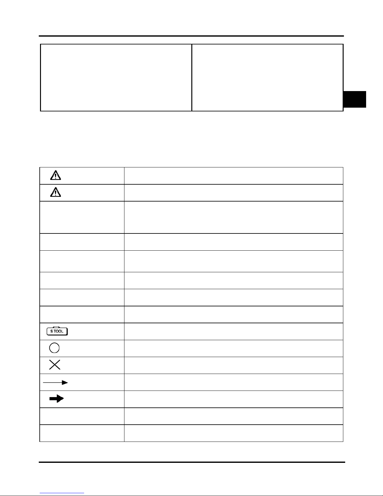
Symbols and Marks
Symbols and marks are used in this manual to indicate what and where the special service are needed, in
case supplemental information is procedures needed for these symbols and marks, explanations will be
added to the text instead of using the symbols or marks.
Warning
Serious injury or even death may occur if procedures are not followed.
Caution
Equipment damages may occur if procedures are not followed.
Engine oil
Recommended oil: Bramax motor oil or equivalent motor oil, SAE 10W-30
API SH class oil. Warranty will not cover the damage which is caused by
not applying with the recommended engine oil.
Grease
King Mate G-3 is recommended.
Locking sealant
Apply sealant; medium strength sealant should be used unless otherwise
specified.
Oil seal
Apply with lubricant.
Renew
Replace with a new part before installation.
Brake fluid
Use recommended brake fluid DOT3 or WELLRUN brake fluid.
Special tools
Use special tools.
Correct
Correct installation.
Wrong
Wrong installation.
Indication Indication of parts.
Directions
Position and operation directions
Parts assembly directions.
Bolt installation direction, --- means that bolt go through the component
(invisible).
Homepage
Contents
1
Simpo PDF Merge and Split Unregistered Version - http://www.simpopdf.com
Page 7
1. General Information
1-2
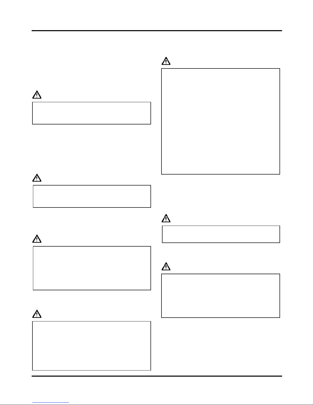
General Safety
Carbon monoxide
If you must run your engine, ensure the place is
well ventilated. Never run your engine in a closed
area. Run your engine in an open area, if you have
to run your engine in a closed area, be sure to use a
ventilator.
Caution
‧ Exhaust contains toxic gas, which may cause
one to lose consciousness and even result in
death.
Gasoline
Gasoline is a low ignition point and explosive
material. Work in a well-ventilated place, no flame
or spark allowed in the work place or where
gasoline is being stored.
Caution
‧ Gasoline is highly flammable, and may
explode under some conditions, keep it away
from children.
Used engine oil
Caution
‧Prolonged contact with used engine oil (or
transmission oil) may cause skin cancer
although it might not be verified.
‧We recommend you to wash your hands with
soap and water right after contacting. Keep the
used oil beyond reach of children.
Hot components
Caution
‧ Components of the engine and exhaust system
can become extremely hot after engine
running. They remain very hot even after the
engine has been stopped for some time. When
performing service work on these parts, wear
insulated gloves and wait until the vehicle is
cooling down.
Battery
Caution
‧ Battery emits explosive gases; flame is strictly
prohibited. Keeps the place well ventilated
when charging the battery.
‧ Battery contains sulfuric acid (electrolyte),
which can cause serious burns, so be careful
not to get the sulfuric acid on your eyes or
skin. If you get battery acid on your skin, flush
it off immediately with water. If you get
battery acid in your eyes, flush it off
immediately with plenty of water and then go
to hospital to consult an ophthalmologist.
‧ If you swallow it by mistake, drink a lot of
water or milk, and take some laxative such as
vegetable oil and then go to see a doctor.
‧ Keep electrolyte beyond reach of children.
Brake shoe
Do not use an air hose or a dry brush to clean
components of the brake system; use a vacuum
cleaner or the equivalent to avoid dust flying.
Caution
˙ Inhaling brake shoe or pad ash may cause
disorders and cancer of the breathing system
Brake fluid
Caution
˙ Spilling brake fluid on painted, plastic, or
rubber parts may cause damage to the parts.
Place a piece of clean cloth on the
above-mentioned parts for protection when
servicing the brake system. Keep the brake
fluid beyond reach of children.
To this chapter contents
Simpo PDF Merge and Split Unregistered Version - http://www.simpopdf.com
Page 8

1. General Information
1-3
Service Precautions
y Always use with SANYANG genuine parts and
recommended oils. Using non-genuine parts for
SANYANG vehicle may damage it.
y Special tools are designed for remove and install
of components without damaging the part. Using
wrong tools may result in damage.
y When servicing this bike, use only metric tools.
Metric bolts, nuts, using wrong tools and
fasteners may damage this vehicle.
y Clean the outside of the parts or the cover before
removing it from the bike. Otherwise, dirt and
deposit accumulated on the part's surface may
fall into the engine, chassis, or brake system,
and cause damage.
y Wash and clean parts with high ignition point
solvent, and blow-dry with compressed air. Pay
special attention to O-rings or oil seals because
most cleaning agents have an adverse effect on
them.
y Never bend or twist a control cable to prevent
unsmooth control and premature worn out.
y Rubber parts may become deteriorated when old,
and easy to be damaged by solvent and oil.
Check these parts before installation to make
sure that they are in good condition, replace if
necessary.
y When loosening a component, which has
different sized fasteners, operate with a diagonal
pattern and work from inside out. Loosen the
small fasteners first. If the bigger ones are
loosen first, small fasteners may receive too
much stress.
y Store complex components such as transmission
parts in the proper assemble order and tie them
together with a wire for ease of installation later.
y Note the reassemble position of the important
components before disassembling them to
ensure they will be reassembled in correct
dimensions (depth, distance or position).
y Components not to be reused should be replaced
when disassembled including gaskets metal seal
rings, O-rings, oil seals, snap rings, and split
pins.
To this chapter contents
Simpo PDF Merge and Split Unregistered Version - http://www.simpopdf.com
Page 9

1. General Information
1-4
y The length of bolts and screws for assembly,
cover plates or boxes is different from one
another; make sure they are correctly installed.
In case of confusion, Insert the bolt into the hole
to compare its length with other bolts, if its
length out side the hole is the same with other
bolts, it is a correct bolt. Bolts for the same
assembly should have the same length.
y Tighten assemblies with different dimension
fasteners as follows: Tighten all the fasteners
with fingers, then tighten the big ones with
special tool first diagonally from inside toward
outside, important components should be
tightened 2 to 3 times with appropriate
increments to avoid warp unless otherwise
indicated. Bolts and fasteners should be kept
clean and dry. Do not apply oil to the threads.
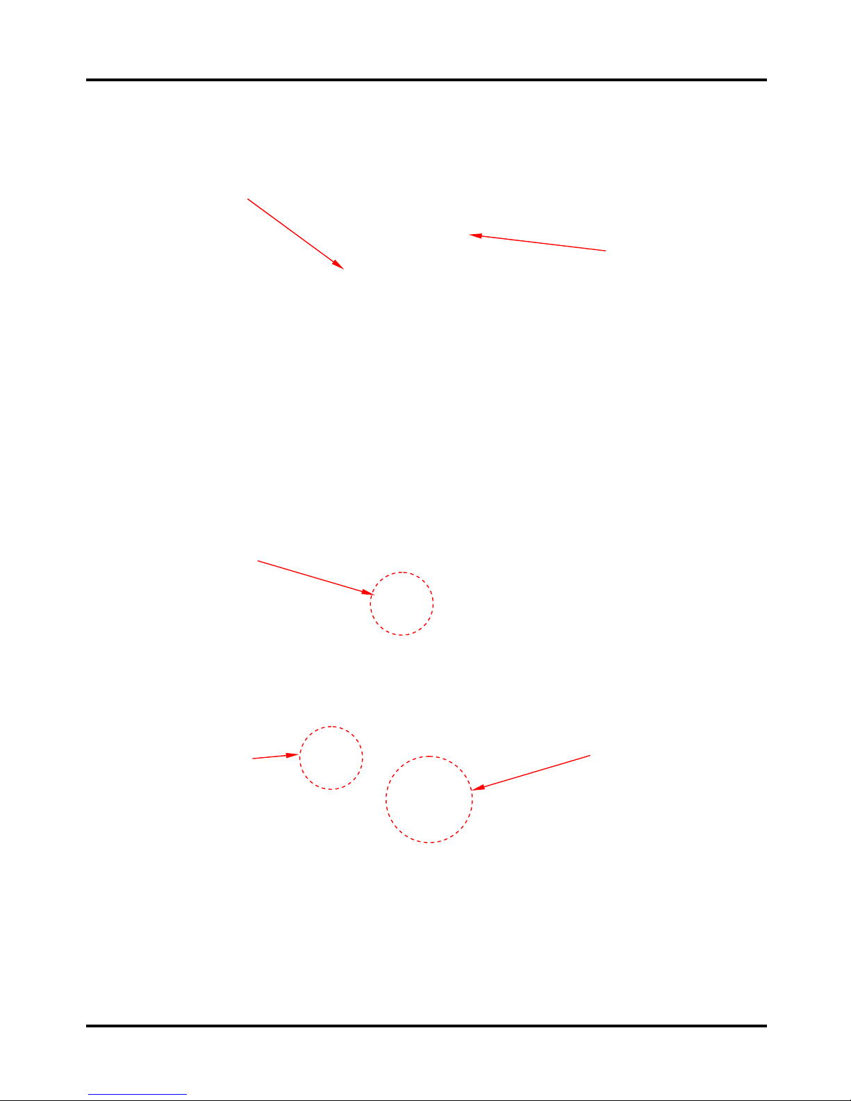
y When oil seal is installed, fill the groove with
grease, install the oil seal with the name of the
manufacturer facing outside, and check the shaft
on which the oil seal is to be installed for
smoothness and for burrs that may damage the
oil seal.
y Remove residues of the old gasket or sealant
before reinstallation, grind with a grindstone if
the contact surface has any damage.
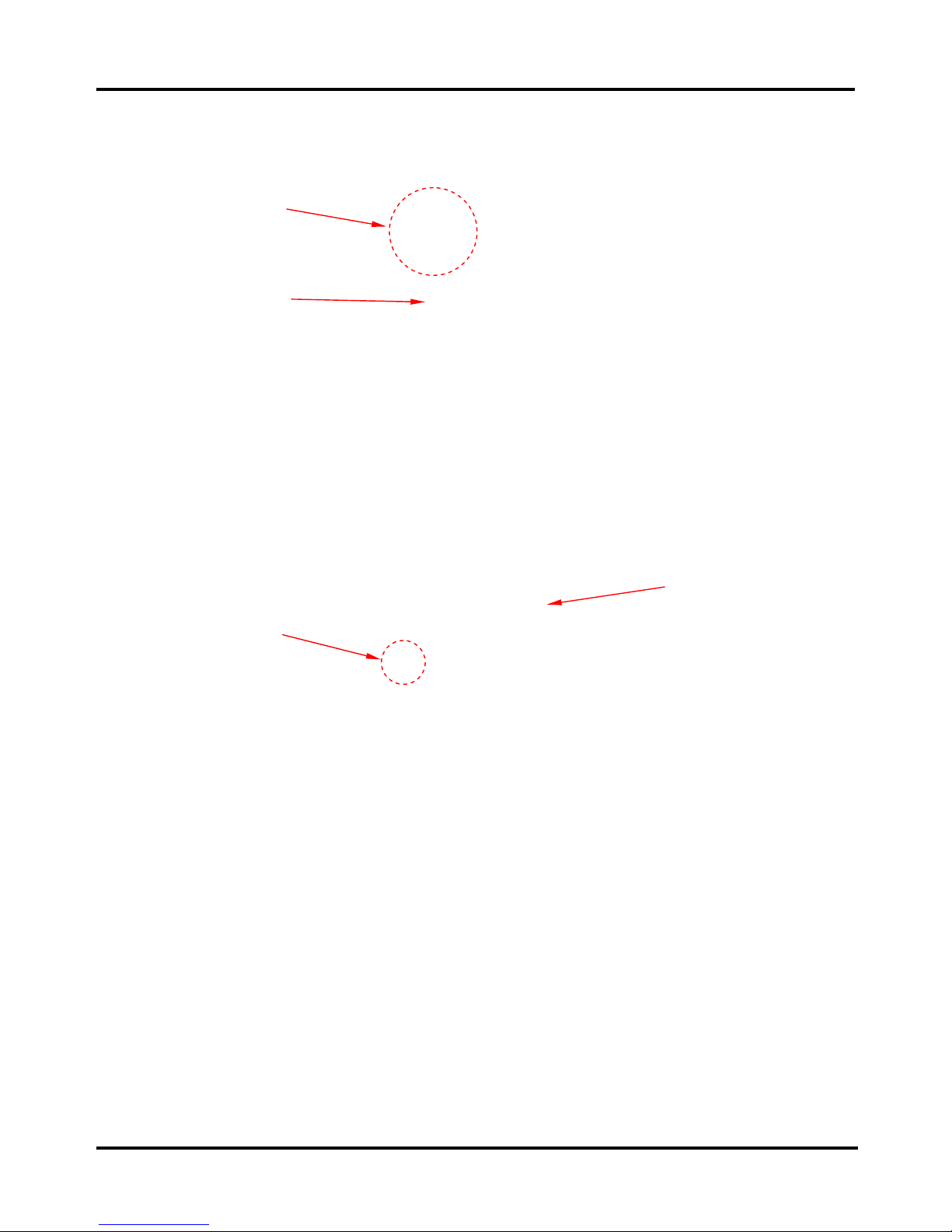
y The ends of rubber hoses (for fuel, vacuum, or
coolant) should be pushed as far as they can go
to their connections so that there is enough room
below the enlarged ends for tightening the
clamps.
y Rubber and plastic boots should be properly
reinstalled to the original correct positions as
designed.
y The tool should be pressed against two (inner
and outer) bearing races when removing a ball
bearing. Damage may result if the tool is pressed
against only one race (either inner race or outer
race). In this case, the bearing should be
replaced. To avoid damaging the bearing, use
equal force on both races.
To this chapter contents
Both of these examples can result in
bearing damage.
Manufacturer's name
Groove
Clamp
Connector
Boots
Simpo PDF Merge and Split Unregistered Version - http://www.simpopdf.com
Page 10

1. General Information
1-5
y Lubricate the rotation face with specified
lubricant on the lubrication points before
assembling.
y Check if positions and operation for installed
parts is in correct and properly.
y Make sure service safety each other when
conducting by two persons.
y Note that do not let parts fall down.
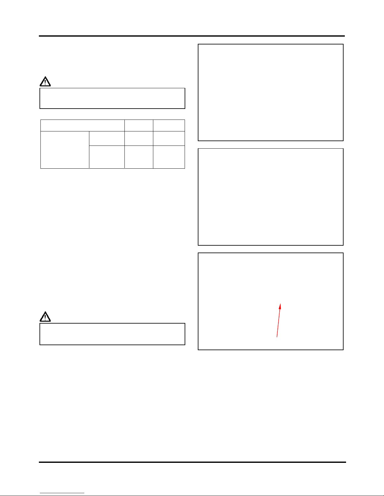
y Before battery removal operation, you have to
remove the battery negative (-) cable first.
Avoid using tools like open-end wrench, which
may contact with body or create spark.
y After service completed, make sure all
connection points is secured.
Battery positive (+) cable should be connected
firstly.
y And the two posts of battery have to be greased
after connected the cables.
y Make sure that the battery post caps are located
in properly after the battery posts had been
serviced.
y If fuse burned, it has to find out the cause and
solved it. And then replace with specified
capacity fuse.
Capacity
verification
To this chapter contents
Simpo PDF Merge and Split Unregistered Version - http://www.simpopdf.com
Page 11

1. General Information
1-6
y When separating a connector, it locker has to
be unlocked first. Then, conduct the service
operation.
y Do not pull the wires as removing a connector
or wires. Hold the connector body.
y Make sure if the connector pins are bent,
extruded or loosen.
y Insert the connector completely.
If there are two lockers on two connector sides,
make sure the lockers are locked in properly.
Check if any wire loose.
y Check if the connector is covered by the twin
connector boot completely and secured properly.
y Before terminal connection, check if the boot is
crack or the terminal is loose.
y Insert the terminal completely.
Check if the boot covers the terminal.
Do not let boot open facing up.
y Secure wires and wire harnesses to the frame
with respective wire bands at the designated
locations. Tighten the bands so that only the
insulated surfaces contact the wires or wire
harnesses.
y Wire band and wire harness have to be clamped
secured properly.
y Do not squeeze wires against the weld or its
clamp.
To this chapter contents
Simpo PDF Merge and Split Unregistered Version - http://www.simpopdf.com
Page 12

1. General Information
1-7
y Do not let the wire harness contact with rotating,
moving or vibrating components when routing
the harness.
y Keep wire harnesses far away from the hot parts.
y Avoid wire harnesses from sharp edges or
corners, and also avoid the jutted-out ends of
bolts and screws.
y Route harnesses so that they neither pull too
tight nor have excessive slack.
y Protect wires or wire harnesses with electrical
tape or tube if they contact a sharp edge or
corner. Thoroughly clean the surface where tape
is to be applied.
y Secure the rubber boot firmly as applying it on
wire harness.
y Never use wires or harnesses which insulation
has been broken. Wrap electrical tape around
the damaged parts or replace them.
y Never clamp or squeeze the wire harness when
installing other components.
Never Touch
Never too
Never clamp or
squeeze the
wire harness
To this chapter contents
Simpo PDF Merge and Split Unregistered Version - http://www.simpopdf.com
Page 13

1. General Information
1-8
y Do not let the wire harness been twisted when
installation.
y Wire harnesses routed along the handlebar
should not be pulled too tight or have excessive
slack, use rubber covering against adjacent or
surrounding parts in all steering perimeters.
y Before operating a test instrument, operator
should read the operation manual of the
instrument. And then, conduct test in accordance
with the instruction.
y Use sand paper to clean connector
pins/terminals if rust is found. And then
continue the connection operation.
Do you know how to set
the instrument to its
measurement position and
the insert locations of its
two probes?
Clean rust
To this chapter contents
Simpo PDF Merge and Split Unregistered Version - http://www.simpopdf.com
Page 14
1. General Information
1-9
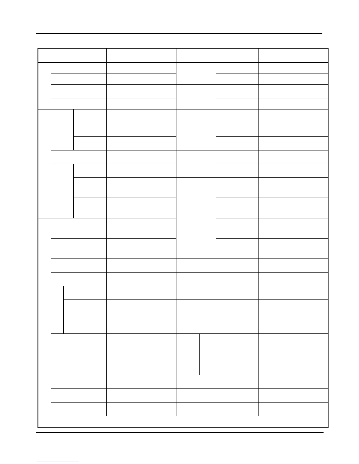
Specifications
Manufacturer SANYANG Model MB10A7-A
Overall Length 1910 mm Front TELESCOPIC
Overall Width 690 mm
Suspension
System
Rear SWING ARM
Overall Height 1055 mm Front 2.50-17 38L
Dimension
Wheel Base 1225 mm
Tire
Specifications
Rear 2.50-17 38L
Front 38 kg
Rear 57 kg
Front Drum (ø 110 mm)
Curb
Weight
Total 95 kg
Brake System
Rear Drum (ø 110 mm)
Passengers/Weight 1 passenger /75 kg Max. Speed Over 80 km/hr
Front 53 kg
Performance
Climb Ability
Below 20°
Rear 117 kg
Primary
Reduction
4.059 (69/17T)
Weight
Total
Weight
Total 170 kg
Secondary
Reduction
2.571 (36/14T)
Type
Air cooled 4-stroke gasoline
engine
Clutch
Wet multi-plate, auto
centrifugal clutch
Installation and
arrangement
Vertical, below center,
incline 15°
Reduction
Transmission 4 speed, circulated
Fuel Used Unleaded gasoline Speedometer 0 ~ 120 km/hr
Fuel system Carburetor Horn 80~110 dB
Bore Ø 52.4 mm Muffler Expansion & Pulse Type
Stroke 47 mm
Exhaust Pipe Position and
Direction
Right side, and
Backward
Cylinder
Arrangement Single Cylinder Lubrication System Forced and wet sump
Displacement 101.4 cc Solid Particulate -
Compression Ratio 9.2 : 1 CO Below 1.8 %
Max HP 6.8 ps / 8500 rpm
Exhaust
Concentration
HC Below 2000 ppm
Max Torque
0.69 kg-m / 6000 rpm
E.E.C.
√
Ignition C.D.I. P.C.V.
√
Engine
Starting System Kick/ Electrical Starter Catalytic Converter
√
To this chapter contents
Simpo PDF Merge and Split Unregistered Version - http://www.simpopdf.com
Page 15
1. General Information
1-10
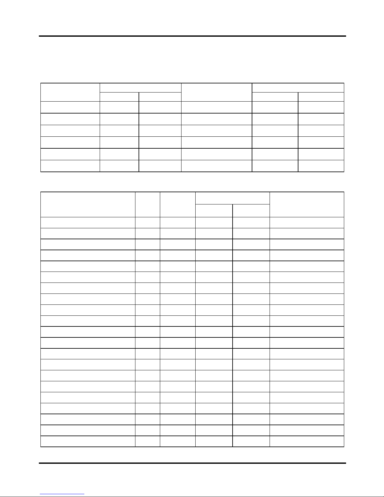
Torque Reference Values
The torque values listed in above table are for more important tighten torque values. Please see standard
values for those not listed in the table.
Standard Torque Values for Reference
Tighten Torque Tighten Torque
Type
kgf-m N-m
Type
kgf-m N-m
5mm bolt、nut
0.45~0.6 4.4~6 4mm screw 0.1~0.15 1.0~1.5
6mm bolt、nut
0.8~1.2 8~12 5mm screw 0.35~0.5 3.4~5
8mm bolt、nut
1.8~2.5 18~25
6mm screw、SH nut
0.7~1.1 7~11
10mm bolt、nut
3.0~4.0 29~39
6mm bolt、nut
1.0~1.4 10~14
12mm bolt、nut
5.0~6.0 49~59
8mm bolt、nut
2.4~3.0 24~29
3mm screw 0.05~0.08 0.5~0.8
10mm bolt、nut
3.5~4.5 34~44
Engine Torque Values
Torque Value
Item
Q’ty
Thread
Dia. (mm)
kgf-m N-m
Remarks
Cylinder head nut
4 8 1.0~1.2 10~12
Cylinder head left bolt
1 6 0.8~1.2 7.8~12
Cylinder stud bolt
4 8 0.7~1.0 7~10
Cylinder head side cover bolt
3 6 0.8~1.2 7.8~12
Tappet adjustment hole cap
2 6 0.8~1.2 7.8~12
Tappet adjustment screw nut
4 5 0.7~1.1 7~11
Apply oil to thread
Cam gear bolt
2 6 1.0~1.2 10~12
Spark plug
1 10 1.0~1.2 10~12
Carburetor insulator bolt
2 6 0.7~1.1 7~11
Engine oil draining bolt
1 12 1.5~2.0 15~20
Clutch nut
1 14 3.8~4.5 38~45
Engine oil strainer cap
2 6 0.8~1.2 7.8~12
Engine oil pump cover screw
2 6 0.3~0.4 3~4
Engine oil pump screw
3 6 0.4~0.6 4~6
Right crankcase cover bolt
10 6 0.8~1.2 7.8~12
Left crankcase cover bolt
8 6 0.8~1.2 7.8~12
Left crankcase rear cover bolt
2 6 0.8~1.2 7.8~12
Driving
2 6 0.8~1.2 7.8~12
ACG. Flywheel nut
1 12 3.5~4.3 35~43
Starting clutch bolt
3 6 1.0~1.4 10~14
Apply glue to thread
Crankcase bolt
7 6 0.8~1.2 7.8~12
To this chapter contents
Simpo PDF Merge and Split Unregistered Version - http://www.simpopdf.com
Page 16

1. General Information
1-11
Frame Torque Values
Torque Value
Item
Q’ty
Thread Dia.
(mm)
(kgf-m) (N-m)
Remarks
Handlebar luck bolt
4 8 3.0~3.5 29~35
Handlebar post locknut
1 10 4.0~4.5 39~49
Steering stem locknut
1 25.4 6.0~8.0 59~78
Steering top cone race
1 25.4 0.15~0.25 1.5~2.5
Front wheel axle nut 1 10 4.0~5.0 39~49
Rear wheel axle nut 1 12 5.0~6.0 49~59
Final driven sprocket nut
1 16 6.0~7.0 59~69
Drive sprocket nut
4 8 2.7~3.3 26~32
Front cushion mounting bolt
2 8 3.0~3.5 29~35
Rear cushion upper connection bolt
2 10 3.0~4.0 29~39
Rear cushion lower connection bolt
2 10 3.0~4.0 29~39
Brake lever nut
2 6 0.8~1.2 7.8~12
R
ear brake drum mounting bolt
1 8 1.5~2.5 15~25
Engine hanger link nut
2 8 3.0~3.5 44~54
Foot stand bolt
4 8 2.4~3.0 24~29
Kick starter bolt
1 6 1.6~1.8 15.7~17.6
Gear change pedal bolt
1 6 1.4~1.5 13.7~14.7
R
ear fork mounting bolt
1 10 3.0~4.0 29~39
Muffler mounting nut
2 6 1.0~1.4 10~13.7
To this chapter contents
Simpo PDF Merge and Split Unregistered Version - http://www.simpopdf.com
Page 17
1. General Information
1-12
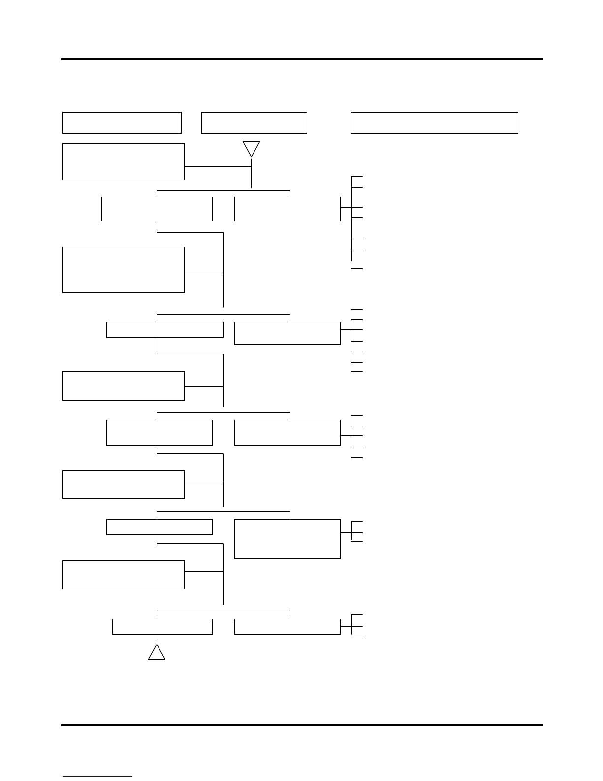
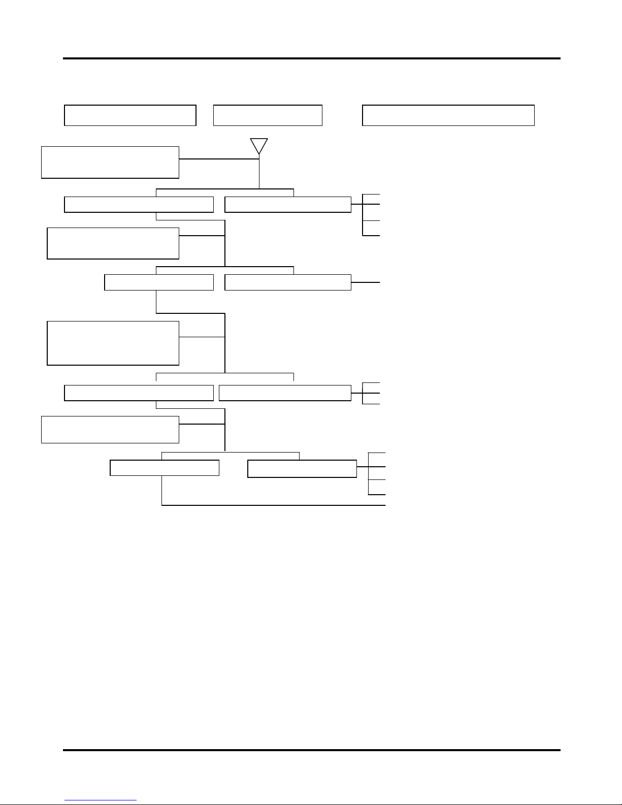
Troubleshooting
A. Engine hard to start or can not be started
Check and adjustment Fault condition Possible causes
Loosen carburetor drain bolt
to check if there is gasoline
inside the
carburetor
Fuel supplied to
carburetor sufficient
No fuel is supplied to
carbureto
r
Remove spark plug, install it
into spark plug cap, and
perform a spark test.
Perform cylinder
compression pressure
test.
Good sparks Weak sparks, no spark
at a
ll
Cylinder compression
pressure normal
Low compression
pressure or no pressure
Re-start by following the
starting procedures
No ignition There are some signs of
ignition; but engine
cannot be started.
Remove the spark plug again
and check it.
Dry spark plug Wet spark plug
1. No fuel in fuel tank
2. Check if the pipes, fuel tank to carburetor
and intake vacuum, are clogged.
3. Float valve clogged
4. Lines in fuel tank evaporation system
clogged
5. Malfunction of fuel pump
6. Loosen or damaged fuel pump vacuum
hose
7. Fuel filter clogged
1. Malfunction of spark plug
2. Spark plug damaged
3. Malfunction of CDI set
4. Malfunction of AC generator
5. Ignition coil is in open or short circuit
6. Ignition coil wire open or short circuit
7. Main switch malfunction
1. Piston ring seized
2. Malfunction of cylinder valves
3. Worn cylinder and piston ring
4. Cylinder gasket leak
5. Sand hole in compression parts
1. Malfunction of throttle valve operation
2. Air leaking through intake manifold
3. Incorrect ignition timing
1. Fuel level in carburetor too high
2. Malfunction of throttle valve operation
3. Throttle valve opening too wide
To this chapter contents
Simpo PDF Merge and Split Unregistered Version - http://www.simpopdf.com
Page 18
1. General Information
1-13
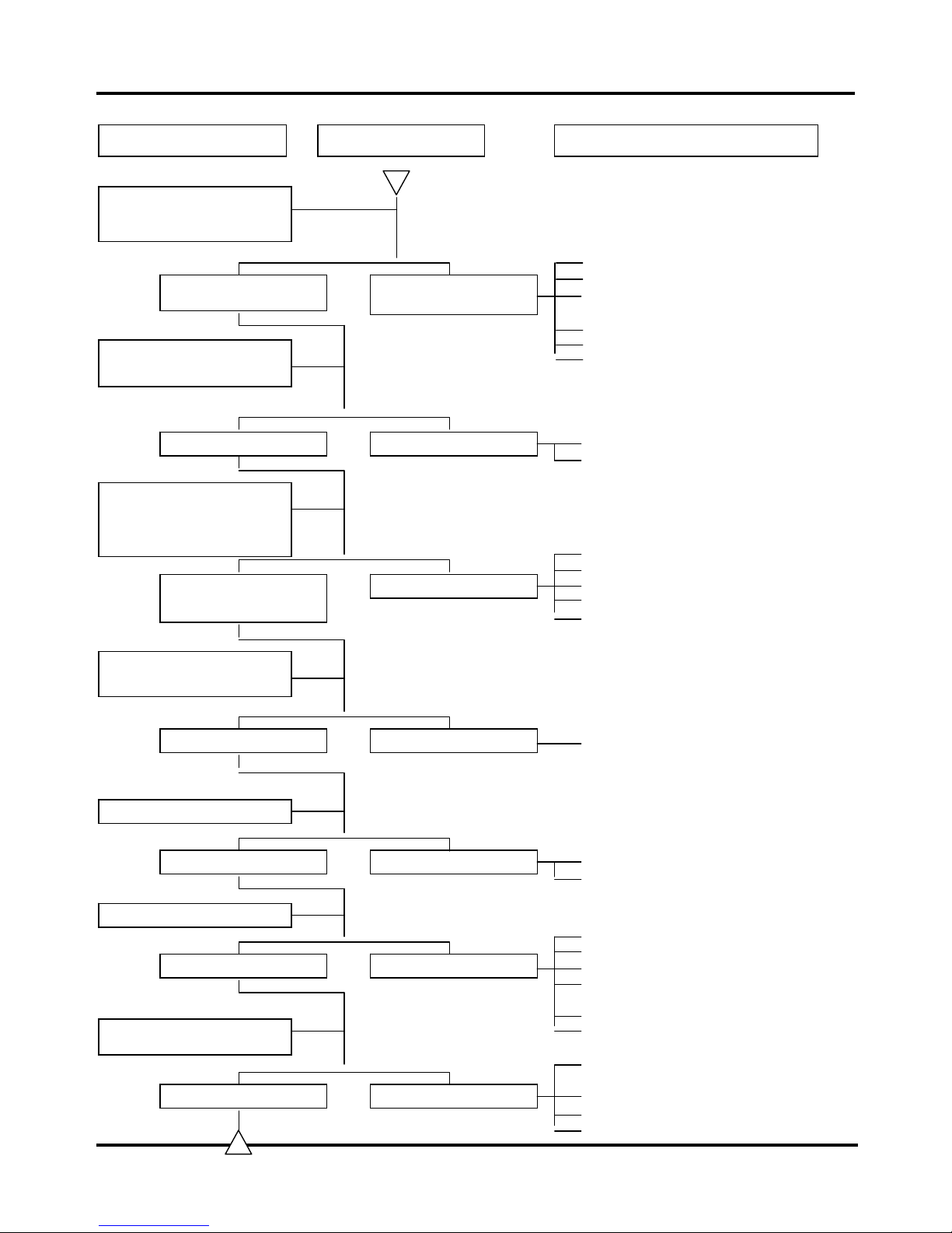
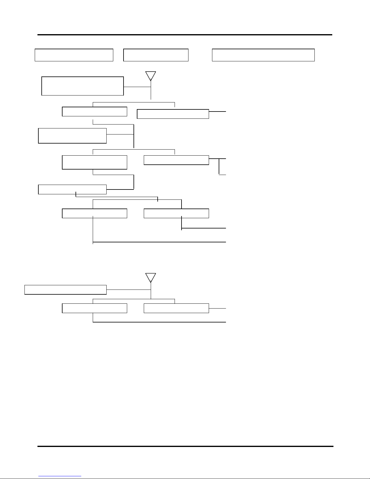
B. Engine run sluggish (Speed does not pick up, lack of power)
Check and adjustment Fault condition Possible causes
Try gradual acceleration and
check engine speed
Engine speed increases. Engine speed cannot
increase.
Check ignition timing
(
Using ignition lamp)
Check cylinder compression
pressure (using compression
pressure gauge)
Correct ignition timing Incorrect ignition timing
Compression pressure
correct
No compression
Check if carburetor jet is
clo
gg
ed
Not clogged Clogged
Remove spark plug
Check if engine over heat
No foul or discoloration Fouled and discoloration
No knock Knock
1. Air cleaner clogged
1. Poor fuel supply
2. Lines in fuel tank evaporation system
clogged
3. Exhaust pipe clogged
4. Fuel level too low in carburetor
5. Fuel nozzle clogged in carburetor.
1. Malfunction of CDI
2. Malfunction of AC alternator
1. Cylinder & piston ring worn out
2. Cylinder gasket leaked
3. Sand hole in compression parts
4. Valve deterioration
5. Seized piston ring
1. Remove foreign object
1. Remove dirt
2. Incorrect spark plug heat range
1. Piston and cylinder worn out
2. Lean mixture
3. Poor fuel quality
4. Too much carbon deposited in
combustion chamber
5. Ignition timing too advanced
6. Poor circuit on the cooling system
Normal Engine overheat
Continually drive in
1. Too much carbon deposited in
combustion chamber
2. Lean mixture
3. Poor fuel quality
4. Ignition timing too advanced
To this chapter contents
Simpo PDF Merge and Split Unregistered Version - http://www.simpopdf.com
Page 19
1. General Information
1-14
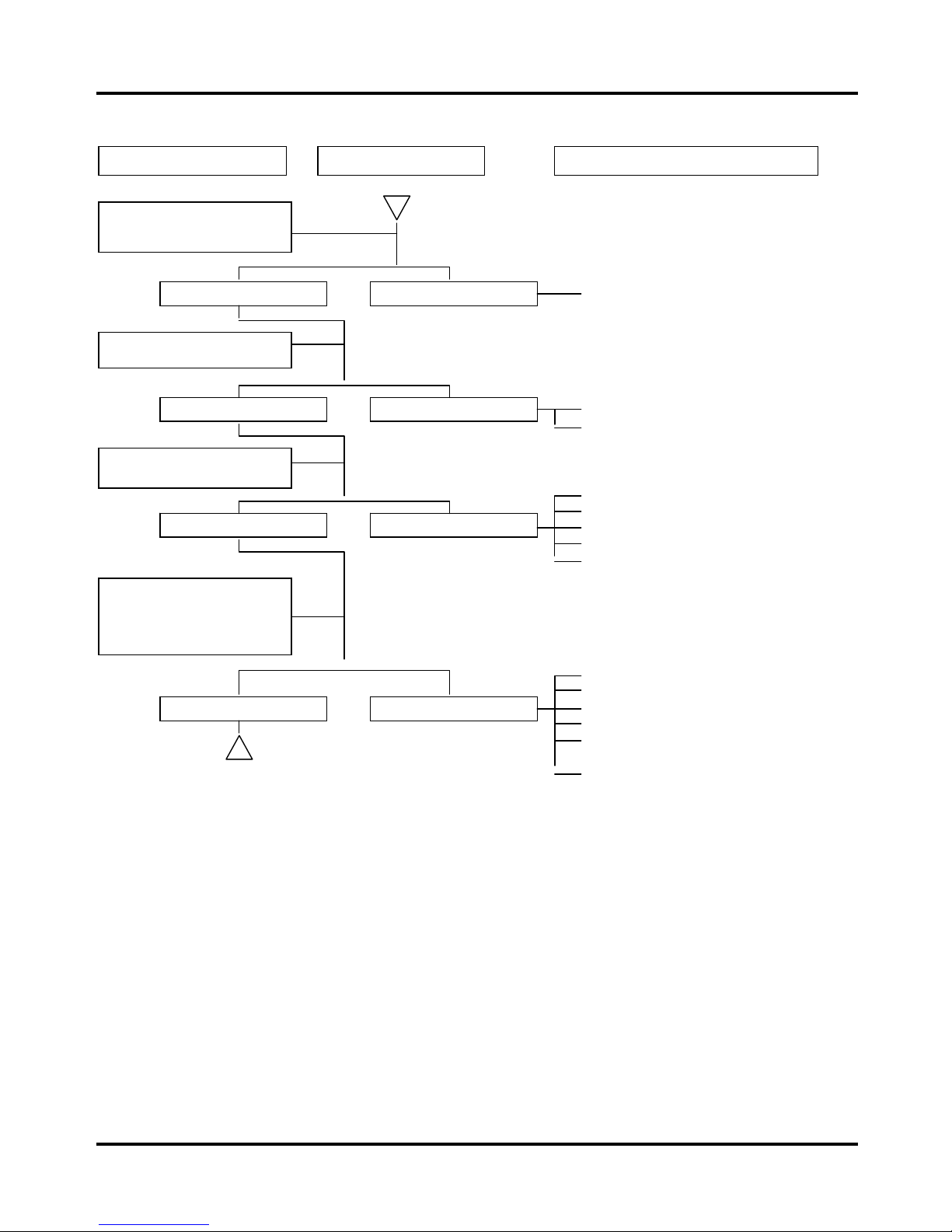
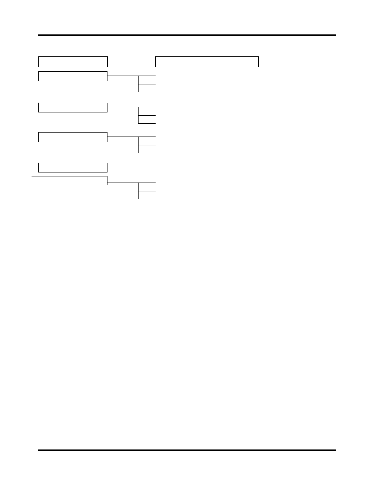
C. Engine runs sluggish (especially in low speed and idling)
Check and adjustment Fault condition Probable causes
Check ignition timing
(Using ignition lamp)
1. Incorrect ignition timing (malfunction
of CDI or AC alternator)
1. Rich mixture (loosen the screw)
2. Lean mixture (tighten the screw)
1. Poor heat insulation gasket
2. Carburetor lock loose
3. Poor intake gasket
4. Poor carburetor O-ring
5. Vacuum hose crack
1. Spark plug fouled
2. Malfunction of CDI
3. Malfunction of AC generator
4. Malfunction of ignition coil
5. Open or short circuit in spark plug
leads
6. Malfunction of main switch
Good spark Poor
No air sucked in Air sucked in
Good Poor
Normal Abnormal
Air sucked in through
carburetor gasket
Adjust the air screw of
carburetor
Remove spark plug, install
spark plug into spark plug
cap and perform spark test
against engine ground
To this chapter contents
Simpo PDF Merge and Split Unregistered Version - http://www.simpopdf.com
Page 20
1. General Information
1-15
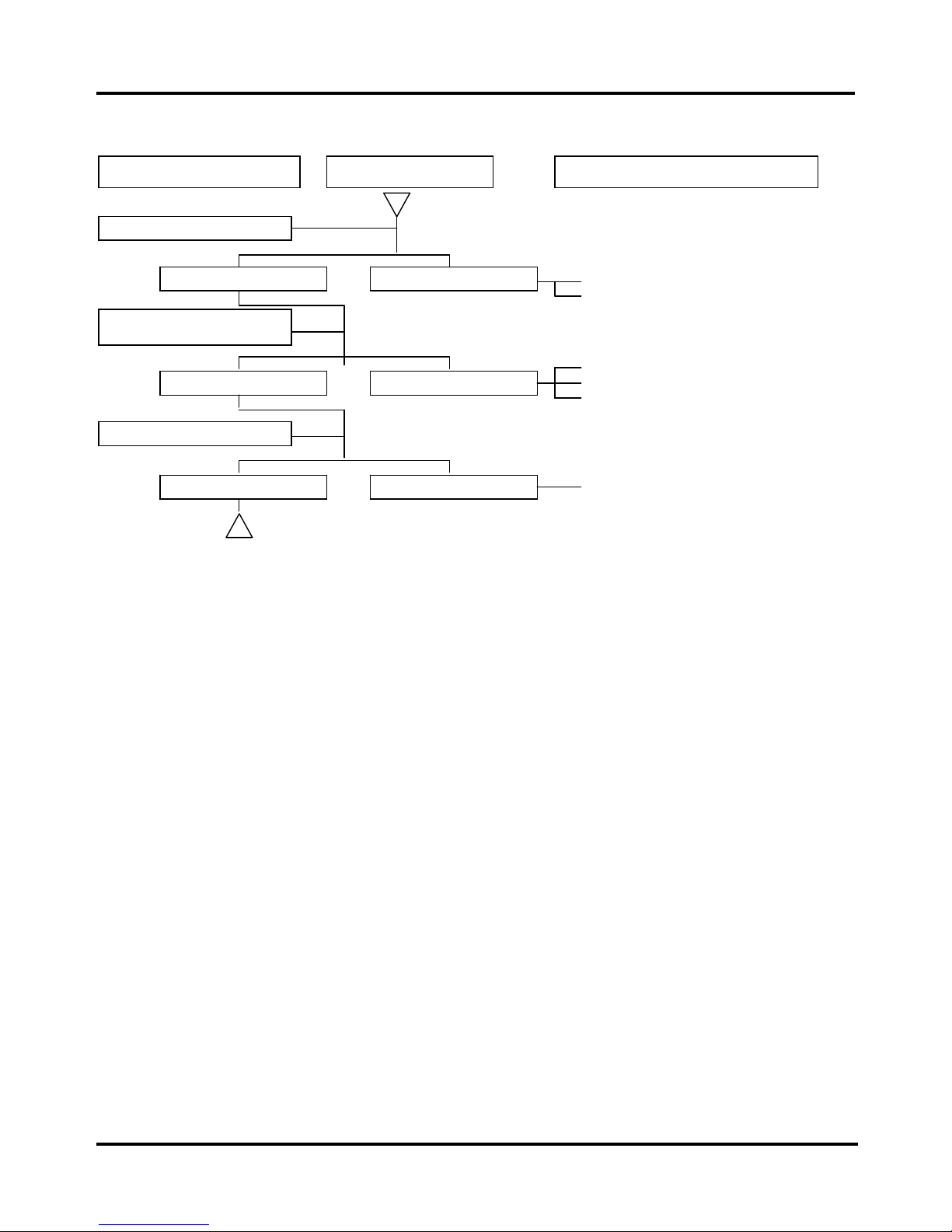
D. Engine runs sluggish (High speed)
Check for fuel supplying
syste
m in
automatic fuel cup
Check if carburetor clogged
1. Insufficient fuel in fuel tank
2. Fuel filter clogged
3. Restricted fuel tank vent
Good Poor
Check and adjustment
Fault condition Probable causes
Check ignition timing
1. Malfunction of CDI
2. Malfunction of AC alternator
Normal Abnormal
Not clogged Clogged
1. Cleaning
To this chapter contents
Simpo PDF Merge and Split Unregistered Version - http://www.simpopdf.com
Page 21
1. General Information
1-16
E. Starter Motor Malfunction
1. Starter Motor doesn’t rotate
To this chapter contents
Check the battery circuit by
activating turning signal
Push the staring button and
check if the starting relay is
activated
Flashing normally Not flashing or dimmed
Braking light is activated
Braking light not activated
Starting relay activated Starting relay not activated
Connect the starting motor to the
battery
1. Bad contact in the starter switch
2. Abnormal Starter relay
3. Loose coupler or terminals
Pull the brake handle or step on
the braking pedal
1. Burnt Fuse
2. Insufficient Battery Voltage
3. Braking Switch abnormal
4. Main switch abnormal
1. Insufficient Battery capacity
(60~120 flashes per minute)
Starter Motor rotates Starter Motor doesn’t rotate
1. Worn carbon brushes
2. Broken or shorted rotor windings
3. Broken Starter motor sub wire
4. Loose coupler
1. Loose coupler
Check and adjustment
Fault condition Possible causes
Simpo PDF Merge and Split Unregistered Version - http://www.simpopdf.com
Page 22
1. General Information
1-17
2. Starting Motor rotates slowly or spins without engagement with crankshaft
3. Starter motor won’t stop rotating
Check the battery circuit by
activating turning signal
Flashing normally
Not flashing or dimmed
1. Insufficient Battery capacity
Connect the starting motor to
the battery
Starting Motor Still rotating
slowl
y
Rotates Normally
Works smoothly Jammed
1. Loose coupler or terminals
2. Starting Relay bad contact
1. Engine Seized.
Kick the kick starter
Turn the main switch off
Motor keeps running Motor stops
1. Starting switch shorted/ stuck
1. Starting relay shorted
1. Starting Motor shorted or damaged
Check and adjustment
Fault condition Possible causes
To this chapter contents
Simpo PDF Merge and Split Unregistered Version - http://www.simpopdf.com
Page 23
1. General Information
1-18
F. Abnormal Engine Noise
Fault condition Possible causes
Rocker arm noise
1. Excessive valve clearance
2. Worn rocker arm
3. Worn camshaft
Piston slapping
1. Worn piston and cylinder
2. Carbon deposit in the combustion chamber
3. Worn piston pin or connecting rod lower end
Cam chain noise
1. Worn camshaft bearings.
2. Worn cam sprocket.
3. Loose or worn cam chain.
Clutch knocking
1. Excessive clutch plate clearance
Transmission gear noise
1. Worn or deteriorated rear wheel damping rubber.
2. Gear surface worn
3. Worn transmission gear set
To this chapter contents
Simpo PDF Merge and Split Unregistered Version - http://www.simpopdf.com
Page 24

1. General Information
1-19
Cable & Wire Routing
Left handlebar switch wire
Left winker wire
Handlebar right side wire band
Right handlebar switch wire
Right winker wire
Front brake switch wire
Left handlebar switch wire
Left winker wire
Right handlebar switch wire
Right winker wire
Front brake switch wire
Speedometer cable
Throttle cable
Front brake cable
Meter wire harness
Headlight wire
To this chapter contents
Simpo PDF Merge and Split Unregistered Version - http://www.simpopdf.com
Page 25

1. General Information
1-20
All cable & wire harness
Apply grease 5~7g to
the inside part of
handlebar post
Handlebar
50mm
Wire harness clamp
Speedometer cable
Front brake cable
Wire harness couplers
After clamp 1 is ready, clamp
all cable and wire harness.)
(Front left winker wire, left
handlebar switch wire,
headlight wire, front right
winker wire, front brake light
switch wire, right handlebar
switch wire and meter wire)
Clamp 2
Clamp 1
To this chapter contents
Simpo PDF Merge and Split Unregistered Version - http://www.simpopdf.com
Page 26
1. General Information
1-21
Speedometer cable
Front brake cable
Make sure all cables and wires go
throu
g
h wire grommet
Push the wire clamp
when the wires are at
right place.
Throttle cable and main wire
harness should be placed
between the left air cleaner
intake duct and the frame.
Main switch coupler
location
To this chapter contents
Simpo PDF Merge and Split Unregistered Version - http://www.simpopdf.com
Page 27
1. General Information
1-22
Secondary air pipe and
winker relay wire should be
clamped.
Located on the rela
y
sta
y
Auto by-starter wire and
main wire harness should
be clamped properly.
AC Generator wire gear
switch couplers should be
packed well and clamped.
PCV drain pipe and carburetor
drain pipe should go through the
hole of body cover stay.
To this chapter contents
Simpo PDF Merge and Split Unregistered Version - http://www.simpopdf.com
Page 28
1. General Information
1-23
Taillight wire, rear winker
wire should be clamped.
Fuel level gauge wire should
be clamped
Rear winker wire should be
clam
p
ed
Rear winker wire should go
through winker stay hole.
To this chapter contents
Simpo PDF Merge and Split Unregistered Version - http://www.simpopdf.com
Page 29

1. General Information
1-24
Lubrication Points
Throttle cable / Front brake lever
pivot
Steering stem
bearing
Rear axle Main stand pivot
Side stand pivot
Speedometer pinion
/ Front axle
Drive chain
To this chapter contents
Simpo PDF Merge and Split Unregistered Version - http://www.simpopdf.com
Page 30
2. Maintenance Information
2-1
Precautions in Operation ············ 2-1
Periodical Maintenance Chart·····2-2
Lubrication System······················2-3
Fuel System·································· 2-4
Air Cleaner···································· 2-5
Throttle Cable Operation·············2-6
PCV System·································· 2-6
Valve Clearance···························· 2-7
Idle Speed Adjustment ················ 2-8
Ignition System ····························2-9
Spark Plug ····································2-9
Compression Pressure················2-10
Clutch Adjustment ······················· 2-11
Drive Chain Adjustment···············2-12
Steering System···························2-13
Suspension System·····················2-13
Brake System ·······························2-14
Tire·················································2-15
Battery···········································2-16
Headlight Adjustment··················2-17
Brake Light Switch·······················2-17
Nuts, Bolts Tightness ··················2-17
Special Tool Catalog····················2-18
Precautions in Operation
Specification
Fuel Tank Capacity 4100 c.c.
Capacity 1000 c.c.
Engine Oil
Changed 800 c.c.
Throttle Cable Free Play 2~6 mm
Spark Plug NGK C6HSA
Spark Plug gap 0.6~0.7 mm
Ignition Timing BTDC 15º±1º / 1600 rpm
Ignition Advance BTDC 32º±1º / 3300 rpm
Idle Speed 1600±100 rpm
Compression Pressure 11±1 kgf/cm² (600 rpm)
Valve Clearance In./Ex. 0.12±0.02 mm
Tire Size
Front/Rear 2.50-17 38L
Single Ride
Front:1.75 kg/cm² / Rear:2.25 kg/cm²
Tire Pressure(Cold)
Tandem Ride
Front:1.75 kg/cm² / Rear:2.75 kg/cm²
Battery Type 12N5A (12V 5Ah)
Brake Lever Clearance 10~20 mm
2
Homepage
Contents
Simpo PDF Merge and Split Unregistered Version - http://www.simpopdf.com
Page 31

2. Maintenance Information
2-2
Periodical Maintenance Schedule
NO
Items
Initial
300KM
1 month or
every
1000KM
3 months or
every
3000KM
6 months or
every
6000KM
1 year or
every
12000KM
1
☆Air filter element
I C C R
2
☆AICV filter
I C C R
3
☆Gasoline filter
I I R
4
☆Engine oil filter
C C C
5
☆Engine oil replacement
R Exchange every 1000 km
6
Tire pressure
I I
7
Battery Inspection
I I
8
Brake lever free play check
I I
9
Steering handle integrity check
I I
10
Shock absorber performance check
I I
11
Bolts tightening check
I I
12
Check the engine for oil leakage
I I
13
☆Spark plug inspection or re placement
I I R
14
☆Change gear oil
R Exchange every 5000 km
15
Lubrication of the whole bike
L
16
Exhaust pipe
I I
17
☆Ignition timing
I I
18
☆Idle emission check
A I A
19
☆Throttle operation
I I
20
☆Engine bolts torque
I I
21
☆Transmission / Chain
I I/L R
22
☆Clutch free play inspection
I I
23
Light/ electrical system/ instrument readings.
I I
24
Main stand/ side stand springs.
I I
25
Fuel lines
I I
27
Cam chain
I I
28
☆Valve clearance
I A
29
☆PCV system integrity
I C
30
☆Crankcase blow-by over-flow pipe
I Drain every 2000km
31
☆Second air injection system (filter)
I I C
32
☆E.E.C. Device check
I
Note:I-Inspection A-Adjustment R-Replacement C-Clean L-Lubrication
Please have your periodical maintenance data recorded by your SYM Authorized Dealer to maintain the motorcycle in excellent
condition. The above maintenance schedule is established by taking the monthly 1,000 kilometers as a reference. Whichevertime or mileage- comes first will be regarded as an index for maintenance.
Remark:These marks “☆” in the schedule are emiss ion control items. A ccording to EPA regulations, these item checks
must be performed period ically fol lo wing the use r ma nua l instr uct ions . It’s prohibited to adjust or repair
these emission control items by unauthorized people. Otherwise, SYM is no responsible.
1. Clean or replace the air cleaner element more often when the motorcycle is operated on dusty roads or in the
Heavily- polluted environment.
2.
Maintenance should be performed more often if the motorcycle is frequently operated in high speed and after the
motorcycle has accumulated a higher mileage.
3. Preventive maintenance:
a. Ignition system-Perform maintenance or check when continuous abnormal ignition, misfire, after-burn, overheating occur.
b. Carbon deposit removal-Remove carbon deposits in cylinder head, piston heads, exhaust system when power is decreasing.
c. Replace worn out pistons, cylinder head.
To this chapter contents
Simpo PDF Merge and Split Unregistered Version - http://www.simpopdf.com
Page 32

2. Maintenance Information
2-3
Lubrication System
Engine Oil Capacity
Caution
z Turn off engine, and park the motorcycle
on flat surface with main stand.
z Check oil level with oil dipstick. (Do not
screw the dipstick into engine when
checking.)
If oil level is near lower limit, fill in the
recommended engine oil to upper limit.
Engine Oil Replacement
Engine off and replace the oil dipstick.
Remove the oil drain bolt under the crankcase
to drain the engine oil.
After completely drain the engine oil, clean the
drain bolt and the washer. If the washer is
deformed or cracked, replace with a new one.
Torque value:3.5~4.5kgf-m
Caution
z Warm up the engine before drain oil, that
will make engine oil easily drained
thoroughly
Fill in the engine oil to the standard capacity.
Oil viscosity SAE 10W-30 Recommended
using Bramax series engine oil.
Engine Oil Capacity
Full disassembly:1000 c.c.
Regular replacement:800 c.c.
Install the dipstick, run the engine for several
minutes. Turn off the engine, and check oil
level again. Check if engine oil leaks.
Engine Oil Strainer Cleaning
Drain engine oil completely.
Remove oil strainer.
Using high pressure air to clean oil strainer is
suggested.
Check if oil strainer is deformed or damaged.
Replace it if necessary.
Reinstall oil strainer and oil strainer cap.
Torque value:0.8~1.2kgf-m
Engine oil drain bolt
Upper limit
Lower limit
2 bolts
To this chapter contents
Simpo PDF Merge and Split Unregistered Version - http://www.simpopdf.com
Page 33

2. Maintenance Information
2-4
Fuel System
Fuel lines
Check all fuel lines, and replace when they
are deteriorated, damaged or leaking.
Caution
z Gasoline is a highly flammable
substance, so any source of fire or spark
is strictly prohibited during operation.
Fuel filter replacement
Warning
z Any source of fire or spark is strictly
prohibited during operation.
z Fuel filter is sealed so cannot be cleaned.
Replace it if it’s clogged.
If fuel filter is clogged, please drain all the
gasoline into a clean container, and wash the
fuel tank.
After replacing the fuel filter and washing the
fuel tank, refill the tank with clean gasoline.
Check the fuel line for leakage.
Vacuum type auto fuel cock
Fuel filter
Negative pressure pipe
Negative pressure pipe
To this chapter contents
Simpo PDF Merge and Split Unregistered Version - http://www.simpopdf.com
Page 34

2. Maintenance Information
2-5
Air Filter
Air filter element
Remove the side cover.
Remove the air filter duct (1 screw).
Remove the air filter cover screw (4 screws).
Open the hold clip and remove the air filter
cover.
Remove the air filter element.
Check the filter element for dirty or damage.
Wash the air filter element with high flash
point solvent (for example, kerosene or diesel)
Squeeze out the cleaning solvent thoroughly,
soak the element into engine oil, and squeeze
out the excessive.
Re-install the filter and the cover.
If the air filter element is too dirty or damaged,
replace it with new parts.
Caution
y Never use gasoline or other low-flash
point solvent for cleaning the element.
wash squeeze
soak squeeze
2 screws on both sides
Screw
Hold clip
To this chapter contents
Simpo PDF Merge and Split Unregistered Version - http://www.simpopdf.com
Page 35

2. Maintenance Information
2-6
Throttle Operation
Operate the throttle grip to see if the throttle
cable is going smoothly. If the throttle cable is
deteriorated, twisted or damaged, replace it
with new part.
If the throttle cable doesn’t operate smoothly,
apply some lubrication oil onto it.
Measure the free play of the throttle grip,
through the inner side flange of it.
Free play:2~6 mm
Please loosen the lock nut and adjust the
throttle cable nut to reach the normal free
play.
PCV System
Unplug the drain pipe, and leak the
deposit off. Drain the pipe every 2,000
km.
Caution
z Under rainy or full- throttle situation, the
maintenance period should be shortened.
You can check the deposit amount
through the transparent pipe.
Drain pipe
2~6 mm
Locknut
To this chapter contents
Simpo PDF Merge and Split Unregistered Version - http://www.simpopdf.com
Page 36

2. Maintenance Information
2-7
Valve Clearance Adjustment
Caution
z The valve clearance should be adjusted
when the engine is cold. (Under 35
degrees Celsius)
Remove the valve clearance-adjusting cap (2
bolts).Remove the cylinder head side cover (2
bolts).
Remove the timing inspection cap and the
AC.G cap on the crankcase L cover.
Use a T socket wrench to rotate the
crankshaft counterclockwise. Align the “T”
mark on the AC.G flywheel with the crankcase
sign, and simultaneously, the cam- chain
sprocket TDC mark aligning with the cylinder
head mark (That means the piston is in the
upper end of compression stroke)
Valve clearance inspection and
adjustment
Check the intake and exhaust valve clearance
by inserting the feeler gauge between the
adjusting screw and the lock nut.
Valve clearance:IN / EX 0.12±0.02 mm
Adjust by loosening the lock nut first, and
turning the adjusting screw until you feel slight
drag on the feeler gauge.
Hold the adjusting screw and tighten the lock
nut.
Caution
z Check the valve clearance after the
adjustment.
Install the valve clearance-adjusting cap,
cylinder head side cover, and the timing
inspection cap and the AC.G cap on the
crankcase L cover.
Caution
z Before installing the O-ring, check if the
O-ring is damaged, and apply some oil on
it to prevent damage during assembly.
2 bolts
〝T〞mark
Timing inspection cap
TDC mark
To this chapter contents
Simpo PDF Merge and Split Unregistered Version - http://www.simpopdf.com
Page 37

2. Maintenance Information
2-8
Idle Speed Adjustment
Caution
z All the other configurations should be
completed before idle speed adjustment.
z The engine must be fully warmed before
the idle speed adjustment.
Use the main stand of the bike, and warm up
the engine. Clip on the RPM sensor (Clip the
RPM sensor clamp on the spark plug cap
wire)
Turn the idle speed adjusting screw to reach
the recommended idle speed.
Recommended idle speed:1600±100rpm
Emission adjustment in idle speed
Warm up the engine for around 10 minutes
and then conduct this adjustment.
1. Connect the tachometer onto engine.
2. Turn the idle speed adjusting screw and let
the engine run at the recommended idle
speed.
3. Insert the exhaust sampling pipe of
exhaust analyzer into the front section of
exhaust pipe. Turn the air fuel ratio
adjusting screw to make the emission
value in idle speed within standard.
4. Slightly accelerate the throttle valve and
release it immediately. Repeat this for 2~3
times.
5. Read the engine RPM and emission value
on the exhaust analyzer. Repeat step 2 to
step 4 procedures until measured value
within standard.
Emission standard: CO:3. 0 % ↓
HC:2000 P.P.M. ↓
Idle speed adjusting screw
Air fuel ratio adjusting screw
Spark plug cap wire
To this chapter contents
Simpo PDF Merge and Split Unregistered Version - http://www.simpopdf.com
Page 38

2. Maintenance Information
2-9
Ignition System
Ignition timing
Caution
z C.D.I ignition system is set by
manufacturer so it cannot be adjusted.
z Ignition timing check procedure is for
checking whether CDI function is normal
or not.
Remove the ignition timing inspection hole
cap on the crankcase left cover.
Connect tachometer and ignition lamp and
start the engine. Keep the engine run in the
idle speed, if the “F” mark meets with the
ignition lamp.
Increase engine RPM to check ignition
advance degree. If the illustrated indent is
within the ignition advance degrees, it means
that the ignition advance degree is in normal.
If ignition timing is incorrect, check CDI set,
pulse rotor and pulse generator. Replace
defective parts if malfunction is found.
Idle Speed:1600±100rpm
Ignition Advance:3300±100rpm
Spark Plug
Recommended spark plug:C6HSA
Remove the spark plug cap.
Clean dirt around the spark-plug hole.
Remove the spark plug.
Measure the spark plug ignition gap.
Spark plug gap:0.6~0.7 mm
Carefully bend ground electrode of the plug to
adjust the gap if necessary.
Hold spark plug and install the spark plug by
screwing it with hand, after tightening the plug
by hands, use plug socket to tighten it to the
standard torque value
Torque value:1.0~1.2kgf-m
Reinstall the spark plug cap.
0.6~0.7mm
Ground electrode
Central electrode
Spark plug cap
Ignition advance indent”װ”
“F” mark
To this chapter contents
Simpo PDF Merge and Split Unregistered Version - http://www.simpopdf.com
Page 39

2. Maintenance Information
2-10
Cylinder Compression Pressure
Warm up the engine and turn it off.
Remove the side cover.
Remove the spark plug cap and the spark
plug.
Install compression gauge into the spark plug
hole, full open the throttle, and kick the kick
starter for several times.
Caution
Rotate the engine until the reading in the
gauge gains no more.
z Usually the highest-pressure reading will
appear in 4~7 seconds.
Compression pressure:11 ±1 Kg/cm²
Check the following items if the pressure
reading is too low:
z Incorrect valve clearance
z Valve leaking
z Cylinder head leaking, piston, piston ring,
cylinder worn out.
If the pressure is too high, it means carbon
deposits in combustion chamber or piston
head.
Compression gauge
Spark plug hole
To this chapter contents
Simpo PDF Merge and Split Unregistered Version - http://www.simpopdf.com
Page 40

2. Maintenance Information
2-11
Clutch Adjustment
Gear change pedal free play inspection
Slightly step on the gear change pedal to
check the free play before clutch
disengagement.
Free play:10~20 mm
Gear change pedal free play adjustment
Before adjusting the gear change pedal,
loosen the locknut first.
Then turn the adjusting screw to achieve the
recommended gear change pedal free play.
Turn the adjusting screw counterclockwise to
decrease the free play of the gear change
pedal. Turn the adjusting screw clockwise to
increase the free play.
After adjustment, fix the adjusting screw and
tighten the locknut.
Caution
z Turn the adjusting screw
counterclockwise to the tightest position,
and then turn the adjusting screw
clockwise 1/8 circle to 1/4 circle.
z Increase or decrease the free play
according to circumstances.
10~20 mm
Adjusting screw
Locknut
1/8~1/4
To this chapter contents
Simpo PDF Merge and Split Unregistered Version - http://www.simpopdf.com
Page 41

2. Maintenance Information
2-12
Drive Chain Adjustment
Drive chain inspection
Place the bike on its main-stand with its
neutral gear.
Check the drive chain slack by moving the
chain up and down by fingers, and measure
the amount of chain slack.
Standard chain slack:10~20 mm
Caution
z Because the front and rear sprocket has
different wearing situation, so please
rotate the rear wheel to find the minimum
chain slack for the measurement.
Drive chain adjustment
If you need to adjust the chain slack, please
loosen the rear axle nut and sleeve nut first.
Turn the left side and the right side adjusting
nut evenly to make the chain slack within the
standard range.
Caution
y Turn the adjusting nuts of both sides
evenly to make the drive chain and
sprockets rotate smoothly.
Turn the nuts clockwise to tighten the chain,
or counterclockwise to loosen the chain
Tighten the sleeve nuts, then the rear axle
nut.
Torque value:4.0~5.0kgf-m
After tightening the rear axle nut, please
check the sleeve nuts to prevent them from
loosening.
Check the chain slack again, and make sure
the rear wheel rotates smoothly.
If the chain is too dirty, use high-flash point
solvents (Kerosene or Diesel) to clean the
chain.
Caution
y Do not use gasoline when cleaning a the
chain. The gasoline will damage the
O-ring in the chain.
After cleaning, lubricate the chain with chain
lubricant.
Sleeve nut
Rear axle nut
Adjusting nut
10~20 mm
To this chapter contents
Simpo PDF Merge and Split Unregistered Version - http://www.simpopdf.com
Page 42

2. Maintenance Information
2-13
Steering Mechanism
Caution
z Check all wires and cables if they are
interfered with the rotation of the steering
handle bar.
Lift the front wheel off the ground.
Turn the handle bar from right to left end and
check if turning is smooth.
If handle bar is uneven or bending, or the
handle bar can be lifted through vertical
direction, adjust the steering top cone race.
Suspension System
Caution
z Do not ride the motorcycle with poor
suspension system.
z Loose, worn or damaged suspension
system will result in poor stability and
maneuverability.
Front cushion
Press down the front cushion for several times
to check its integrity.
Check if any oil leaks or damage found.
Replace relative parts if damage found.
Tighten all nuts and bolts.
Rear cushion
Press down the rear cushion for several times
to check its integrity.
Check if any oil leaks or damage found.
Replace rear cushion if any damage found.
Park the motorcycle with main stand.
Move the rear wheel sideways forcefully to
see if the swing arm bushing and pivot nut are
loosened.
Tighten all nuts and bolts.
Locknut
Steering top cone race
To this chapter contents
Simpo PDF Merge and Split Unregistered Version - http://www.simpopdf.com
Page 43

2. Maintenance Information
2-14
Brake System
Front drum brake lever free play inspection
Pull the front brake lever slightly, and measure
the free play before brake engagement.
Free play:10~20 mm
Turn the brake adjusting nut to adjust the free
play. Turn the brake adjusting nut clockwise to
decrease the free play. Turn the nut
counterclockwise to increase the free play.
Rear disk brake pedal free play inspection
Press down the brake pedal slightly, and
measure the free play before brake
engagement.
Free play:20~30 mm
Turn the brake adjusting nut to adjust the free
play. Turn the brake adjusting nut clockwise to
decrease the free play. Turn the nut
counterclockwise to increase the free play.
Brake lining inspection
When pressing the brake pedal down, if the
arrow mark on the braking arm reaches the
triangle mark on the brake panel, it means
that the brake lining needs to be changed.
Please refer to Chapter 11 and 12 for brake
lining exchange process.
Brake system integrity confirmation
Caution
z After changing the brake lining or the
brake cable, you must check the brake
system to see if it works well or not.
10~20mm
20~30mm
Arrow mark
Triangle mark
Adjusting nut
To this chapter contents
Simpo PDF Merge and Split Unregistered Version - http://www.simpopdf.com
Page 44
2. Maintenance Information
2-15
Tire
Check the tire pressure to see if it’s in the
specified pressure range.
Caution
z Check the tire pressure when the tire is
cold.
Specified tire pressure range
Tire pressure Front Rear
Single ride 1.75 2.25
Tire pressure
when cold
(Kg/cm²)
With
passenger
1.75 2.75
Specified tire:
Front/Rear:2.50-17 38L
Check the tire surface for embedded nails,
stones or other objects.
Check if front and rear tires pressure is
normal.
If the wearing of the tire thread reaches
triangle △ mark index, the tire also have to
be replaced.
Measure the tire thread depth at the center of
the tire, and if the depth is not enough, please
replace the tire.
Minimum tire tread depth:
Front:1.5 mm
Rear:2.0 mm
Caution
z Wear mark index〝△〞is located along the
tire wall.
“△” mark
To this chapter contents
Simpo PDF Merge and Split Unregistered Version - http://www.simpopdf.com
Page 45

2. Maintenance Information
2-16
Battery
Battery removal
Remove the right side cover.
Unplug the ventilation tube.
Remove the battery holder (2 bolts).
Remove the〝─〞negative pole first, then
remove the〝+〞positive pole.
Remove the battery.
If the battery liquid level is too low, please
remove the top plug, and fill in distilled water
to the upper limit.
Caution
z Don’t fill in too much distilled water, or the
electrolyte may overflow and corrode the
frame.
z Only distilled water is allowed. If any
impure water is filled in, it will shorten the
battery life.
Warning
z The electrolyte contained sulfuric acid.
Please avoid touching the eyes, skin, or
clothes. If any contact by accident, please
flush with plenty of water.
If there is some rust on battery posts, clean it
with steel brush.
Install the battery in the reverse procedures of
removal.
Caution
z If the rust on the posts is very serious,
spray some hot water on them. Then,
more easily you can remove the rust by
steel brush.
z Apply some grease on the posts after
cleaning rust to prevent from happening
again.
Ventilation tube
2 bolts
To this chapter contents
Simpo PDF Merge and Split Unregistered Version - http://www.simpopdf.com
Page 46

2. Maintenance Information
2-17
Headlight Adjustment
Start the engine, turn on the headlight.
Loosen the headlight lock bolt, move the
headlight upward or downward to adjust the
headlight beam height.
When the proper headlight beam height is
reached, tighten the lock bolt.
Caution
z The factory setting of the beam height is
consistent with government orders.
z Improper headlight beam setting will
make driver in the opposite lane dazzled
and cause danger.
Brake Switch
Brake switch inspection
When the brake lever is pulled, the brake
switch will light up the brake lamp.
Make sure that electrical starter can be
activated only under braking condition.
Rear brake switch adjustment
Turn on the main switch.
When the brake pedal is stepped down for
20mm,the brake lamp should be activated.
If the brake lamp is not activated or activated
too early, adjust through the rear brake switch
adjusting nut.
Turning clockwise will decrease the free play,
and counterclockwise to increase the free
play.
Nuts, Bolts Tightness
Apply periodical maintenance in according
with the Periodical Maintenance Schedule.
Check if all the bolts and nuts on the frame
are tightened well.
Check all fixing pins, snap rings, hose (pipe)
clamps, and wire holders for security.
Rear brake switch adjusting nut
Headlight lock bolt
Brake switch
To this chapter contents
Simpo PDF Merge and Split Unregistered Version - http://www.simpopdf.com
Page 47
2. Maintenance Information
2-18
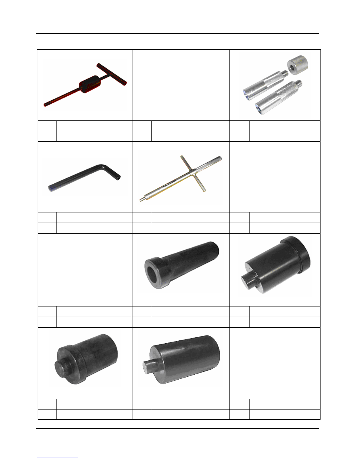
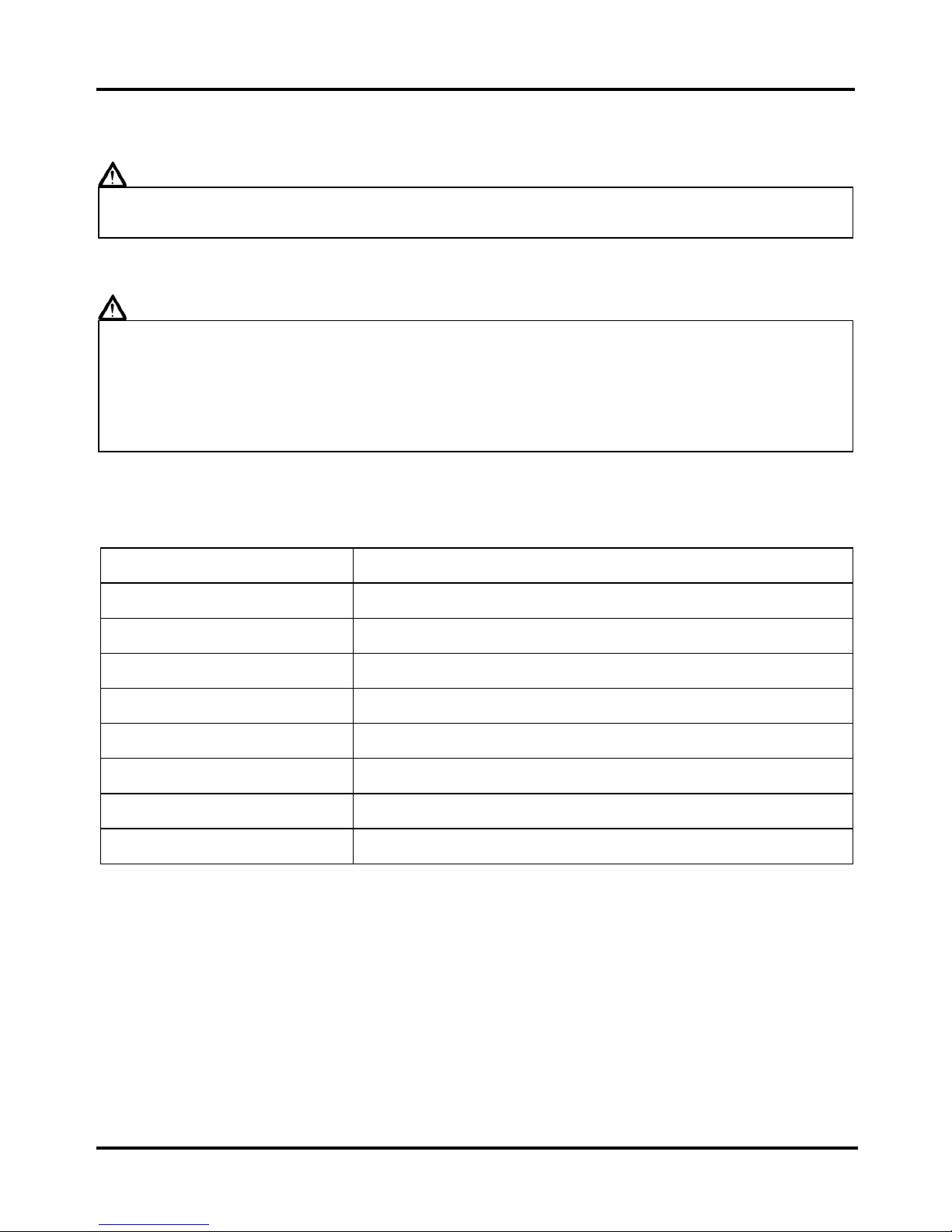
Special Tool Catalog
Name
Rocker arm shaft disassemble tool
Name Valve spring compressor Name
Valve remove/ assemble tool
SY No. SYM-1445100 SY No. SYM-1471100 SY No. SYM-1471110/20
Name Tappet adjusting wrench Name TAPPET ADJUSTING TOOLS Name ACG puller
SY No. SYM-9001200 SY No. SYM-9001210 SY No. SYM-3110A00
(20*32*6)
(6203/6004UZ)
Name Special nut socket Name Oil seal driver Name Bearing driver
SY No. SYM-9023100-SY125 SY No. SYM-9120200 SY No. SYM-9620000
(6204)
(6301)
Name Bearing driver Name Bearing driver Name Bush puller
SY No. SYM-9110400 SY No. SYM-9610000 SY No. SYM-1120310
To this chapter contents
Simpo PDF Merge and Split Unregistered Version - http://www.simpopdf.com
Page 48

2. Maintenance Information
2-19
Name
Steering stem locknut remove/
assemble tool
Name Steering top cone race wrench Name Universal bearing driver
SY No. SYM-5320000 SY No. SYM-5320020 SY No. SYM-6204024
Name Inner bearing puller set Name Outer bearing puller Name Electrical gauge
SY No. SYM-6204020 SY No. SYM-6204001 SY No. SYM-HE07007-01
To this chapter contents
Simpo PDF Merge and Split Unregistered Version - http://www.simpopdf.com
Page 49

2. Maintenance Information
2-20
Note:
To this chapter contents
Simpo PDF Merge and Split Unregistered Version - http://www.simpopdf.com
Page 50

3. Fuel System
3-1
Mechanism Diagram ···················3-1
Precautions in Operation ···········3-2
Troubleshooting··························3-3
Carburetor Removal····················3-4
Throttle Valve ······························3-6
Float Chamber / Jet Set ············· 3-7
Carburetor Installation··············· 3-10
Idle Speed Adjustment ·············· 3-11
Fuel Tank ···································· 3-12
Air Cleaner·································· 3-14
0BMechanism Diagram
Fuel gauge
Fuel tank
To vacuum tube
Vacuum type fuel cock
Carburetor
Fuel outlet tube
3
Homepage Contents
Simpo PDF Merge and Split Unregistered Version - http://www.simpopdf.com
Page 51
3. Fuel System
3-2
1BPrecautions in Operation
General information
Warning
Gasoline is a low ignition point and explosive materials, so always work in a well-ventilated
place and strictly prohibit flame when working with gasoline.
Caution
z Gasoline is a low ignition point and explosive materials, so always work in a well-ventilated
place and strictly prohibit flame when working with gasoline.
z When disassembling fuel system parts, pay attention to O-ring position, replace with new
one as re-assembly.
z There is a drain screw in the float chamber for draining residual gasoline.
z Do not disassemble the auto by-starter and air cut valve arbitrarily.
Specification
Item Specification
Carburetor diameter Ø 16 mm
I.D. number PTE004D
Fuel level 10.2 mm
Main injector # 58
Idle injector # 40
Idle speed 1600±100 rpm
Throttle free play 2~6 mm
Pilot screw 1 3/4 turns
Torque value
Carburetor locknut 0.7~1.1kgf-m
Special service tool
Vacuum/air pressure pump
General tool
Float Chamber fuel level gauge
To this chapter contents
Simpo PDF Merge and Split Unregistered Version - http://www.simpopdf.com
Page 52

3. Fuel System
3-3
2BTroubleshooting
Engine cannot be started
z No fuel in fuel tank
z Clogged fuel tube
z Excessive fuel in cylinder
z No spark from spark plug (malfunction of
ignition system)
z Clogged air cleaner
z Malfunction of auto by-starter
z Throttle cable damaged
Engine stalled after being started
z Malfunction of auto by-starter
z Incorrect ignition timing
z Malfunction of carburetor
z Improper engine oil
z Air leakage into inlet manifold
z Incorrect idle speed settings.
Unstable idle speed
z Abnormal ignition system
z Incorrect idle settings.
z Abnormal carburetor
z Impure fuel
Misfire during acceleration
z Malfunction of ignition system
Late ignition timing
z Malfunction of ignition system
z Malfunction of carburetor
Weak engine power
z Fuel system clogged
z Malfunction of ignition system
Fuel / Air Mixture too lean
z Clogged carburetor jet
z Carburetor parts stick and closed
z Malfunction of float valve
z Fuel level too low in float chamber
z Clogged fuel tank cap vent
z Clogged fuel filter
z Obstructed fuel pipe
z Clogged air vent hose
z Air leakage into inlet manifold
Fuel / Air Mixture too rich
z Clogged air injector
z Malfunction of float valve
z Fuel level too high in float chamber
z Malfunction of auto by-starter
z Dirty air cleaner
To this chapter contents
Simpo PDF Merge and Split Unregistered Version - http://www.simpopdf.com
Page 53

3. Fuel System
3-4
3BCarburetor Removal
Removal
Remove the body side cover.
Put a container near the fuel drain screw, and
loosen it. Drain all the fuel of the float
chamber.
Warning
z Gasoline should stay away from fire, and
avoid getting on the frame. If gasoline
gets on the frame, please wash it off
immediately.
Disconnect the auto by-starter coupler.
Disconnect the fuel pipe.
Disconnect the breather pipe and remove the
winker relay.
Auto by-starter coupler
Breather pipe
Winker relay
Fuel pipe
Fuel drain screw
To this chapter contents
Simpo PDF Merge and Split Unregistered Version - http://www.simpopdf.com
Page 54

3. Fuel System
3-5
Remove the carburetor top cover by turning it
counterclockwise. Remove the top cover,
throttle cable, and throttle valve.
Loosen the clamp from the air cleaner side
and remove the pipe.
Remove the carburetor lock bolts.
Remove the insulator and the carburetor.
Installation
Install as the reversed order of removal
procedures.
Torque value:
Carburetor holding nuts:0.7~1.1kgf-m
After installation, the following adjustment is
required:
● Throttle cable free play.
● Idle speed adjustment.
Adjusting nut
Locknut
Throttle valve
Air cleaner clamp
Top cover
2 bolts
To this chapter contents
Simpo PDF Merge and Split Unregistered Version - http://www.simpopdf.com
Page 55

3. Fuel System
3-6
4BThrottle Valve
Disassembly
Compress the throttle spring and disassemble
the throttle cable, and the spring.
Turn the jet needle seat counterclockwise to
remove the jet needle and the seat from the
throttle valve.
Check the throttle valve and the jet needle to
see if they are damaged or not.
Assembly
Assemble as reversed order of removal
procedures.
Jet needle
Jet needle seat
Throttle valve
Top cover
Spring
To this chapter contents
Simpo PDF Merge and Split Unregistered Version - http://www.simpopdf.com
Page 56

3. Fuel System
3-7
5BFloat Chamber / Jet Set
Remove 2 mounting screws and remove float
chamber cover.
Warning
z Please fill the gasoline in float chamber
into the fuel tank.
Remove the float pin.
Remove the float and float valve.
Inspection
Check the float valve and valve seat for any
damage or blocking.
Caution
z In case of worn out or dirty, the float valve
and valve seat will not close tightly. The
fuel will overflow. A worn out or dirty float
valve must be replaced with a new one to
fix the problem.
Check if worn out
Float valve
Float
Float pin
Float pin
2 screws
To this chapter contents
Simpo PDF Merge and Split Unregistered Version - http://www.simpopdf.com
Page 57

3. Fuel System
3-8
Cleaning
Remove the main jet, main jet seat and slow
jet.
Remove the air adjusting screw.
Caution
z Be careful not to damage jets and
adjusting screw.
z Before removing the adjusting screw, turn
it all the way in clockwise and record the
number of circles.
z Do not turn the adjusting screw forcefully,
or the valve seat may be damaged.
z When the air adjusting screw is removed,
take out the inner washer with it.
Clean the jets with Carburetor conditioner.
Then use compressed air to blow the dirt off.
Air adjusting screw
Main jet
Slow jet
To this chapter contents
Main jet
Slow jet
Air adjusting screw
Main jet seat
Spring
Main fuel passage
Slow fuel passage
Slow air passage
Simpo PDF Merge and Split Unregistered Version - http://www.simpopdf.com
Page 58

3. Fuel System
3-9
Assembly
Before assembling, please blow the fuel
passages with compressed air.
Assemble the air adjusting screw.
Caution
● Please assemble the air adjusting screw
with the same setting circles as removal.
Assemble the main jet seat, main jet and slow
jet.
Assemble the float valve, float and float pin.
Main jet
Slow jet
Air adjusting screw
Float pin
To this chapter contents
Simpo PDF Merge and Split Unregistered Version - http://www.simpopdf.com
Page 59

3. Fuel System
3-10
Fuel level inspection
Caution
y Check the float valve and float for proper
installation.
y To get the correct reading, position the fuel
level gauge in the way that float chamber
face is vertical to the main jet.
Fuel level:10.2mm
Assemble the fuel cup after confirming the fuel
level.
6BCarburetor Installation
Install the carburetor in the reverse order of
removal.
Following adjustments must be made after
installation.
● Throttle cable free play adjustment.
● Idle speed adjustment
Fuel level gauge
2 screws
Adjusting nut
Locknut
To this chapter contents
Simpo PDF Merge and Split Unregistered Version - http://www.simpopdf.com
Page 60

3. Fuel System
3-11
7BIdle Speed Adjustment
Caution
y Air-screw was set at factory, so no
adjustment is needed. For easy
installation, count the number of circles it
takes to screw the air-screw to the bottom.
y The idle adjustment process must be done
while the bike is on its main stand.
Use a tachometer while adjusting engine
RPM.
Screw in air adjusting screw gently, then back
up to standard circles.
Standard setting:1 3/4 circles
Warm up the engine fully; adjust the throttle
stopper screw of throttle valve to achieve the
standard idle RPM.
Standard idle speed:1600rpm±100
Connect the hose of exhaust analyzer to
exhaust front end. Press test key on the
analyzer.
Adjust the air adjustment screw and read CO
reading on the analyzer.
Standard value of CO emission:1.0~1.5 %
Gradually increase the throttle, make sure rpm
and CO value are within the standard range
after engine running stable. If rpm and CO
value fluctuated, repeat the procedures above
for achieving the standard value.
Idle adjusting screw
Air adjusting screw
To this chapter contents
Simpo PDF Merge and Split Unregistered Version - http://www.simpopdf.com
Page 61

3. Fuel System
3-12
8BFuel Tank
Fuel tank removal
Remove the license plate bracket (2 bolts).
Remove the rear right / left winkers, and the
rear fender (1 bolt, 1 screw).
Remove the rear top cover.
Disconnect the fuel unit wire coupler.
Open the seat.
Disassemble the fuel-vapor tube to the carbon
canister.
1 screw
2 bolts
Wire coupler
Fuel-vapor tube
1 bolt
To this chapter contents
Simpo PDF Merge and Split Unregistered Version - http://www.simpopdf.com
Page 62

3. Fuel System
3-13
Remove the right body cover, and remove
the battery.
Remove the fuel outlet pipe and the vacuum
pipe from the Vacuum operated automatic fuel
cock.
Lift the fuel tank with the fuel tank cover.
Remove the lock bolts to separate the cover
from the fuel tank.
Fuel unit removal
Remove the fuel unit (3 screws).
Refer to the chapter 12 for the detailed
inspection for the fuel unit.
Fuel outlet tube
3 screws
Vacuum operated automatic fuel cock
Vacuum tube
2 bolt for both sides
To this chapter contents
Simpo PDF Merge and Split Unregistered Version - http://www.simpopdf.com
Page 63

3. Fuel System
3-14
9BAir Cleaner
Air filter element
Remove the body cover.
Loosen the air duct clamp (1 screw).
Remove the air cleaner cover screws.
Open the air cleaner lock clip and remove the
air cleaner cover.
Remove the air filter element.
Check if the air filter element is dirty or
damaged.
Wash the air filter element with non-flammable
or high flash-point solvent (Like kerosene or
diesel).
After washing, squeeze it and dump into motor
oil, and squeeze again.
If the element is too dirty or damaged, please
change a new one.
Caution
y Don’t use gasoline or other flammable
solvents to clean the element.
wash squeeze
dump into engine oil squeeze
4 screws for both sides
1 screw
Lock clip
Air filter element
To this chapter contents
Simpo PDF Merge and Split Unregistered Version - http://www.simpopdf.com
Page 64

3. Fuel System
3-15
Air cleaner removal
Remove the body cover.
Remove the air cleaner connecting tube and
the fuel vapor recycle tube.
Loosen the air cleaner duct band, and remove
the air cleaner ducts (both sides).
Remove the air cleaner (2 bolts on both
sides).
Installation
Install as the reversed order of removal.
2 bolts on both sides
1 clamp
Fuel vapor recycle tube
Air cleaner duct band
To this chapter contents
Simpo PDF Merge and Split Unregistered Version - http://www.simpopdf.com
Page 65

3. Fuel System
3-16
Note:
To this chapter contents
Simpo PDF Merge and Split Unregistered Version - http://www.simpopdf.com
Page 66

4. Lubrication / Clutch / Transmission
4-1
Mechanism Diagram .................... 4-1
Mechanism Diagram .................... 4-2
Precautions in Operation ............ 4-3
Troubleshooting........................... 4-4
Engine Oil ..................................... 4-5
Engine Oil Strainer Cleaning....... 4-5
Clutch Removal ............................ 4-6
Clutch Inspection ......................... 4-8
Clutch Installation ........................ 4-9
Gear Shift Mechanism.................. 4-12
Oil Pump Removal / Inspection...4-16
Oil Pump Assembly / Installation 4-18
Mechanism Diagram
4
Anti loose nut
3.8~4.5kgf-m
Clutch outer
Primary drive gear
Clutch weight
Clutch spring
Clutch set ring
Clutch friction dick B
Clutch plate A
Clutch center
Clutch outer cover
Flexible washer
Lock washer
Primary driven gear
Oil pump drive gear
Oil pump
Oil pump driven gear
Oil filter screen
Oil drain bolt
Clutch plate B
Clutch plate C
Clutch friction disk A
Clutch friction disk A
Drive gear outer
Drive plate Clutch damper spring
Bearing 6000
Homepage Contents
Clutch free spring
Simpo PDF Merge and Split Unregistered Version - http://www.simpopdf.com
Page 67

4. Lubrication / Clutch / Transmission
4-2
Mechanism Diagram
Shift drum retainer
Shift drum cam
Clutch lever
Clutch lifter plate
Gear shift spindle
Gear shift arm
Clutch cam plate
Ball retainer
Cam plate spring
Clutch adjusting bolt
Gear shift arm return spring
Gear shift arm pivot pin
Shift drum stopper
Shift drum stopper spring
Shift drum pin
Shift drum pin guide
Shift drum plate
Bearing 6805
Gear shift drum
Shift fork
Shift fork
Shift fork shaft
S
hift fork shaft
Gear change switch
Gear indication drill
Gear indication drill spring
Gear shift arm master
Gear shift arm master spring
To this chapter contents
Simpo PDF Merge and Split Unregistered Version - http://www.simpopdf.com
Page 68

4. Lubrication / Clutch / Transmission
4-3
Precautions in Operation:
General Information
z This chapter covers the engine oil pump and the oil replacement.
z The disassembly of the clutch and the shifting linkage is covered. All these operations can be
done while the engine is still on the motorcycle.
Specification
Engine Oil Capacity:
After disassembly:1000 c.c.
After draining:800 c.c.
Recommended engine oil viscosity:
SAE 10W-30
(The Bramax series oil is recommended)
Engine oil viscosity
Measurement: mm
Item Standard Service Limit
Clearance between inner rotor and
outer rotor
0.30 0.35
Clearance between outer rotor
and the pump body
0.30~0.36 0.40
Oil pump
Clearance between rotor and
pump cover
0~0.06 0.11
Clutch pedal free play 10~20 Spring free length 16.35 15.50
Clutch friction disk A thickness 2.55~2.68 2.20
Clutch friction disk A thickness 3.35~3.45 3.00
Clutch
Clutch plate warp - 0.20
Torque value
Oil drain bolt 1.5~2.0kgf-m
Oil filter cover bolt 0.8~1.2kgf-m
Oil pump cover screw 0.3~0.4kgf-m
Oil pump screw 0.4~0.6kgf-m
Clutch anti-loosen nut 3.8~4.5kgf-m
Right crankcase bolt 0.8~1.2kgf-m
Special tool
Clutch anti-loosen nut socket wrench SYM-9023100-SY125
To this chapter contents
Simpo PDF Merge and Split Unregistered Version - http://www.simpopdf.com
Page 69

4. Lubrication / Clutch / Transmission
4-4
Troubleshooting
Engine oil level too low
y Oil leakage
y Worn valve guide or stem seal
y Worn piston ring
Engine oil pressure too low
y Oil level low
y Clogged oil filter, passage
y Damaged oil pump
Engine contamination
y Oil or filter not changed regularly
y Damaged cylinder head gasket
y Worn piston ring
Clutch slips during acceleration
y Worn clutch plate
y Weak clutch spring
Bike trembles
y Bent clutch plate
Hard to shift gear
y Improper
y bent shift fork shaft
Gear shift pedal won’t return
y Broken or weak gear shift arm return spring
y Bent shift fork shaft
Gear jumps out
y Bent shift fork
y Bent shift fork shaft
y Damaged shift drum stopper spring
To this chapter contents
Simpo PDF Merge and Split Unregistered Version - http://www.simpopdf.com
Page 70

4. Lubrication / Clutch / Transmission
4-5
Engine Oil
Turn off the engine, and park the motorcycle
on flat surface with main stand.
Check the oil level with the oil dipstick.
Do not screw the dipstick in while checking.
If oil level is low, fill into recommended oil to
reach the upper limit.
Engine oil replacement
Caution
z Drain the engine oil when the engine is
fully warmed up, so the oil can be drained
out completely.
Place an oil basin under the bike, and remove
oil drain bolt.
After all oil is drained, make sure washer can
be re-used, and re-install oil drain bolt.
If the Oil drain bolt washer is damaged, it
should be replaced.
Torque value:1.5~2.5kgf-m
Oil Filter Screen Cleaning
Remove the oil filter screen cover (2 bolts).
Remove the oil filter screen.
Clean the oil filter screen with compressed air.
Check the cover washer and the oil filter
screen for any damage. Replace it with new
one if necessary.
Install the oil filter screen and the cover.
Torque value:0.8~1.2kgf-m
Fill in engine oil (oil viscosity SAE 10W-30)
Recommended using Bramax series oil.
Engine oil capacity: 800 c.c. Regular
exchange.
Install dipstick, run the engine for several
minutes. Then turn off the engine, and check
the oil level again.
Check if engine oil leaks.
Drain bolt
Upper
limit
Lower
limit
2 bolts
To this chapter contents
Simpo PDF Merge and Split Unregistered Version - http://www.simpopdf.com
Page 71

4. Lubrication / Clutch / Transmission
4-6
Clutch Removal
Drain the engine oil.
Remove the footrest, exhaust pipe and
kick-starter.
Remove the right crankcase cover (8 bolts).
Remove the clutch lift plate, ball retainer and
clutch cam plate spring.
Remove the clutch lever and clutch cam plate.
Remove the clutch outer cover (4 screws).
8 bolts
Clutch cam plate spring
Clutch ball retainer
4 screws
Clutch lever
Clutch cam plate
To this chapter contents
Clutch outer cover
Simpo PDF Merge and Split Unregistered Version - http://www.simpopdf.com
Page 72

4. Lubrication / Clutch / Transmission
4-7
Open the location foot of the lock washer.
Remove the anti-loose locknut.
Remove the flexible washer, lock washer and
the whole clutch assembly.
Special tool:
Anti-loosen locknut socket wrench
SYM-9023100-SY125
Remove the clutch set ring.
Remove the drive gear outer, clutch center,
clutch plates and clutch friction disks from the
clutch outer.
Disassemble the drive gear outer, clutch
center, clutch plates and clutch friction disks.
Location foot
Clutch set ring
Clutch plate
Clutch center
Drive gear outer
Clutch friction disk B
Anti-loose nut
Clutch free spring
Clutch friction disk A
To this chapter contents
Simpo PDF Merge and Split Unregistered Version - http://www.simpopdf.com
Page 73
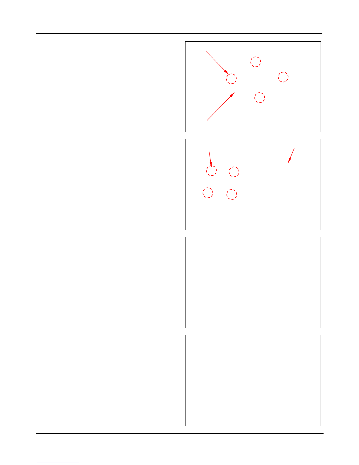
4. Lubrication / Clutch / Transmission
4-8
Remove the clutch drive plate screws (4
screws) and disassemble the clutch drive
plate from the clutch outer.
Remove the clutch spring.
Clutch Inspection
Clutch spring inspection
Measure the free length of four clutch springs.
Service limit:15.5mm
Clutch friction disk inspection
Measure the thickness of each clutch friction
disk. If it’s under service limit or it’s damaged,
replace it with a new one.
Service limit:Friction disk A 2.2mm
Friction disk B 3.0mm
Clutch outer
4 screws
Clutch damper spring
Clutch spring
To this chapter contents
Simpo PDF Merge and Split Unregistered Version - http://www.simpopdf.com
Page 74

4. Lubrication / Clutch / Transmission
4-9
Clutch plate inspection
Use a feeler gauge to measure the warp of
each clutch plate.
Service limit:0.2mm
Clutch outer inspection
Check the clutch outer to see if any cracks or
damage can be found.
Clutch Installation
Assemble the clutch drive plate onto the
clutch outer (4 screws) and install the clutch
damper spring in the clutch outer.
Reinstall the clutch plate, clutch friction disks,
clutch center and drive gear outer.
4 screws
Clutch damper spring
To this chapter contents
Simpo PDF Merge and Split Unregistered Version - http://www.simpopdf.com
Page 75

4. Lubrication / Clutch / Transmission
4-10
Reinstall the clutch set ring.
Assemble the clutch assembly to the
crankshaft.
Put the anti-loose lock washer first and then
the flexible washer.
After the anti-loose locknut is installed, bend
any one location foot of the lock washer to fit
in the locknut.
Install the clutch outer cover (4 screws).
Install the clutch cam plate.
Make the clutch lever aim at the breach of the
clutch cam plate and install the clutch lever
onto the gear shift spindle.
Clutch set ring
Location foot
Anti-loose locknut
4 screws
Clutch lever
Clutch cam plate
To this chapter contents
Simpo PDF Merge and Split Unregistered Version - http://www.simpopdf.com
Page 76

4. Lubrication / Clutch / Transmission
4-11
Install the clutch cam plate side spring, ball
retainer, and clutch lifter plate onto the clutch
cam plate.
Install the right crankcase cover (8 bolts).
Reinstall the kick starter, gear shift pedal,
footrest and exhaust pipe.
Refill the specified engine oil.
Loosen the locknut of the clutch adjusting bolt.
Turn the clutch adjusting bolt
counterclockwise to the end and then turn it
clockwise 1/8~1/4 circle to adjust the clutch
free play.
After the clutch clearance adjustment, lock the
adjusting bolt and then the locknut.
Caution
z Increase or decrease the clutch
clearance according to the real
circumstance.
Turn clockwise 1/8~1/4 circle
8 bolts
To this chapter contents
Simpo PDF Merge and Split Unregistered Version - http://www.simpopdf.com
Page 77

4. Lubrication / Clutch / Transmission
4-12
Gear Shift Linkage Mechanism
Gear shift linkage mechanism removal
Remove the gear shift pedal (1 bolt).
Drain out the engine oil.
Remove the footrest, kick starter and exhaust
pipe.
Remove the right crankcase cover.
Remove the clutch lever and the clutch
assembly.
Remove the primary driven gear cir clip.
Remove the primary driven gear.
Remove the shift drum stopper and stopper
spring (1 bolt).
Remove the shift drum cam and shift drum pin
guide (1 bolt).
Shift drum cam
Cir clip
1 bolt
Shift drum stopper
To this chapter contents
Simpo PDF Merge and Split Unregistered Version - http://www.simpopdf.com
Page 78

4. Lubrication / Clutch / Transmission
4-13
Pull out the gear shift spindle and gear shift
arm.
Remove the shift drum pin guide and gear
shift drum pins.
Remove the shift drum plate location pin and
prevent it from being lost.
Inspection
Check the gear shift spindle and gear shift
arm for wear or damage.
Gear shift spindle
Shift drum pin guide
Shift drum plate location pin
To this chapter contents
Simpo PDF Merge and Split Unregistered Version - http://www.simpopdf.com
Page 79

4. Lubrication / Clutch / Transmission
4-14
Check the shift drum stopper and stopper
spring for wear or damage.
Check the shift drum cam for wear or damage.
Check the shift drum plate and shift drum pin
for wear or damage.
Gear shift linkage mechanism assembly
Install the shift drum plate location pin onto the
gear shift drum.
Shift drum plate location pin
To this chapter contents
Simpo PDF Merge and Split Unregistered Version - http://www.simpopdf.com
Page 80

4. Lubrication / Clutch / Transmission
4-15
Install the shift drum plate and shift drum pin
onto the gear shift drum.
Install the gear shift spindle and gear shift
arm.
Caution
z The gear shift spindle location finger must
pass through movement limit hole of the
gear shift arm.
z The claw of gear shift arm must hook up
with shift drum pins.
Install the shift drum pin guide and shift drum
cam (1 bolt).
Install the shift drum stopper and stopper
spring (1 bolt).
Torque value:0.8~1.2kgf-m
Caution
z After the shift drum stopper is reinstalled,
make sure it operates well.
Install the primary driven gear and put on the
cir clip.
Install the primary drive gear, clutch assembly,
and linkage mechanism.
Install the crankcase location pin, new
crankcase gasket and right crankcase cover.
Install the kick starter, gear shift pedal, footrest
and exhaust pipe.
Fill in the specified engine oil.
Shift drum plate
Claw of gear shift arm
Movement limit hole
Shift drum cam
Shift drum stopper
To this chapter contents
Gear shift spindle location finger
Simpo PDF Merge and Split Unregistered Version - http://www.simpopdf.com
Page 81

4. Lubrication / Clutch / Transmission
4-16
Oil Pump Removal / Inspection
Drain out the engine oil.
Remove the footrest and exhaust pipe.
Remove the kick starter (1 bolt).
Remove the right crankcase cover (8 bolts)
and clutch assembly.
Remove the primary drive gear.
Special tool:
Special nut socket wrench
SYM-9023100-SY125
Remove the oil pump (3 screws).
Caution
z Impact screwdriver is allowed to be used
to remove the oil pump lock screws.
Oil pump disassembly
Remove the cir clip, washer and oil pump
driven gear
Remove the oil pump driven gear location pin.
Location pin
Oil pump drive gear
3 screws
Primary drive gear
Cir clip
To this chapter contents
Simpo PDF Merge and Split Unregistered Version - http://www.simpopdf.com
Page 82

4. Lubrication / Clutch / Transmission
4-17
Remove the oil pump cover and washer (3
screws).
Oil pump inspection
Check the clearance between the oil pump
and outer rotor.
Service limit:Under 0.35 mm
Check the clearance between the inner and
outer rotor.
Service limit:Under 0.40mm
Check the clearance between the surface of
oil pump and rotor.
Service limit:Under 0.11 mm
3 screws
To this chapter contents
Simpo PDF Merge and Split Unregistered Version - http://www.simpopdf.com
Page 83

4. Lubrication / Clutch / Transmission
4-18
Oil Pump Assembly / Installation
Assemble the inner and outer rotor into the oil
pump body.
Install the oil pump drive shaft.
Install the oil pump cover and washer (3
screws).
Torque value:0.3~0.4kgf-m
Caution
z Make sure the oil pump rotate smoothly.
Install new o-rings.
Install the oil pump driven gear location pin.
Install the oil pump driven gear and cir clip.
O ring
3 screws
Cir clip
Location pin
To this chapter contents
Simpo PDF Merge and Split Unregistered Version - http://www.simpopdf.com
Page 84

4. Lubrication / Clutch / Transmission
4-19
Install the oil pump (3 screws).
Torque value:0.4~0.6kgf-m
Install the oil pump drive gear onto the
crankshaft and make the teeth of oil pump
drive gear and driven gear coordinate.
Install the primary drive gear.
Install the clutch assembly and clutch lever.
Install the location pin and new right
crankcase cover gasket.
Install the right crankcase cover (8 bolts).
Torque value:0.8~1.2kgf-m
Oil pump drive gear
3 screws
Primary drive gear
Clutch lever
Clutch cam plate
8 bolts
To this chapter contents
Simpo PDF Merge and Split Unregistered Version - http://www.simpopdf.com
Page 85

4. Lubrication / Clutch / Transmission
4-20
Note:
To this chapter contents
Simpo PDF Merge and Split Unregistered Version - http://www.simpopdf.com
Page 86

5. AC. Generator / Starting Clutch
5-1
Mechanism Diagram····················· 5-1
Precautions in Operation············· 5-2
AC. Generator Stator Removal········5-3
AC. Generator / Starting Clutch ······5-6
Mechanism Diagram
5
1.0~1.4kgf-m
0.8~1.2kgf-m
3.5~4.3kgf-m
Homepage Contents
Starter motor
Flywheel
ACG Stator
Starter reduction
gear shaft
Starter reduction gear
Starter clutch gear
Starter clutch outer body
Clutch outer cover
Clutch roller 9*10mm
Spring cap
Roller spring
Simpo PDF Merge and Split Unregistered Version - http://www.simpopdf.com
Page 87

5. AC. Generator / Starting Clutch
5-2
Precautions in Operation
General information
z For engine troubleshooting and inspection, refer to the first chapter.
z For starting Motor repairing process and cautions, refer to Chapter 13.
Specification Measurement unit:mm
Item Service limit
Starter clutch gear exterior diameter 35.91
Starter clutch outer interior diameter 37.8
Torque value
Flywheel locknut 3.5~4.3kgf-m
Left crankcase cover bolt 0.8~1.2kgf-m
Starter clutch inner-hexagon bolts 1.0~1.4kgf-m with screw adhesive
Special tool
Flywheel puller SYM-3110A00
To this chapter contents
Simpo PDF Merge and Split Unregistered Version - http://www.simpopdf.com
Page 88

5. AC. Generator / Starting Clutch
5-3
ACG Stator Replacement
Stator replacement
Remove the body cover.
Disconnect the ACG coupler.
Disconnect the gear change switch coupler.
Remove the gear shift pedal (1 bolt).
Remove the left crankcase rear cover (2
bolts).
Remove the left crankcase cover (7 bolts).
Rubber cover
1 bolt
7 bolts
2 bolts
To this chapter contents
Simpo PDF Merge and Split Unregistered Version - http://www.simpopdf.com
Page 89

5. AC. Generator / Starting Clutch
5-4
Remove the foreign objects and gasket
residue on the interface of crankcase and
cover.
Remove the pulse coil (2 screws) and ACG
stator (2 bolts).
ACG stator inspection
Check the following circuit for electricity
conductivity.
White ~ Green 0.7Ω±10%
Yellow ~ Green 0.5Ω±10%
Black / Red ~ Green 780Ω±10%
Blue / Yellow ~ Green 110Ω±10%
2 screws
2 bolts
Yellow
Black / Red
Blue / Yellow
White
Green
To this chapter contents
Simpo PDF Merge and Split Unregistered Version - http://www.simpopdf.com
Page 90

5. AC. Generator / Starting Clutch
5-5
ACG stator assembly
Assemble the ACG stator (2 bolts) and pulse
coil (2 screws).
Assemble the stator wire correctly onto the left
crankcase cover with the rubber seal.
Install the location pins and new left crankcase
gasket.
Install the left crankcase cover (7 bolts).
Rubber seal
7 bolts
Location pins
To this chapter contents
Simpo PDF Merge and Split Unregistered Version - http://www.simpopdf.com
Page 91

5. AC. Generator / Starting Clutch
5-6
ACG Flywheel / Starting One-way
Clutch
ACG flywheel / starting clutch removal
Remove the flywheel / starting one-way clutch
with flywheel puller.
Special tool:
ACG flywheel puller SYM-3110A00
Remove the starter clutch gear and needle
bearing
Remove the cir clip and starter reduction gear.
Remove the starter reduction gear shaft (2
screws).
Flywheel puller
Starter clutch gear
Cir clip
Starter reduction gear
2 screws
To this chapter contents
Simpo PDF Merge and Split Unregistered Version - http://www.simpopdf.com
Page 92

5. AC. Generator / Starting Clutch
5-7
Check the starter reduction gear and shaft for
any wear or damage.
Measure the inner diameter of starter
reduction gear.
Service limit:
Inner diameter:Under 13.02 mm
Measure the exterior diameter of starter
reduction gear shaft.
Service limit:
Exterior diameter:Over 12.96 mm
Starter clutch inspection
Install the starter clutch gear onto the starter
clutch outer.
Hold the starter clutch and turn the starter
clutch gear.
Make sure the starter clutch gear can only be
turned counterclockwise.
Check the starter clutch gear for any wear or
damage.
Measure the exterior diameter of the starter
clutch gear.
Service limit:
Exterior diameter:over 35.91 mm
To this chapter contents
Starter clutch gear
Simpo PDF Merge and Split Unregistered Version - http://www.simpopdf.com
Page 93

5. AC. Generator / Starting Clutch
5-8
Starter clutch disassembly
Remove the starter clutch inner-hexagon
bolts.
Separate the starter clutch outer body and the
clutch outer cover.
Disassemble the clutch rollers, spring caps,
and springs.
Check if the rollers and spring caps are worn
or damaged.
Assemble the rollers, spring caps, and
springs.
Measure the inner diameter of the starter
clutch outer.
Service limit:
Inner diameter:under 37.8 mm
Assembly
Assemble in the reversed process of
disassembly.
Caution
z Apply some screw- adhesive on the
thread of inner-hexagon bolts.
Torque value:1.0~1.4kgf-m
Roller spring
Clutch roller
Spring cap
Clutch outer body
Clutch outer cover
Roller spring
Clutch roller
Spring cap
Clutch outer body
Clutch outer cover
To this chapter contents
Simpo PDF Merge and Split Unregistered Version - http://www.simpopdf.com
Page 94

5. AC. Generator / Starting Clutch
5-9
Flywheel / starter clutch installation
Install the starter reduction gear shaft (2
bolts).
Install the starter reduction gear and cir clip.
Install the ACG flywheel, starter clutch and
starter clutch gear (1 locknut).
Torque value:5.0~6.0kgf-m
Install the location pins and new gasket onto
the crankcase.
2 screws
Cir clip
Locknut
Location pins
To this chapter contents
Simpo PDF Merge and Split Unregistered Version - http://www.simpopdf.com
Page 95

5. AC. Generator / Starting Clutch
5-10
Assemble the stator wire correctly onto the left
crankcase cover with the rubber seal.
Install the left crankcase cover (7 bolts).
Torque value:1.5~2.0kgf-m
Install the left crankcase rear cover (2 bolts).
7 bolts
Rubber seal
2 bolts
To this chapter contents
Simpo PDF Merge and Split Unregistered Version - http://www.simpopdf.com
Page 96

6. Engine Removal
6-1
Precautions in Operation ···········6-1
Engine Removal··························6-2
Engine Intallation ························6-5
Precautions in Operation
General information
● During maintenance of a removed engine, you need to use an adjustable rack or cart to
support the engine.
● The following parts can be repaired with the engine staying on the frame:
1. Carburetor
2. AC. Generator
3. Starting clutch
4. Clutch
5. Gear shift mechanism
6. Cylinder / Piston
7. Cam chain tensioner
8. Cam shaft / Rocker arm
● You must remove the engine for repairing the following parts:
1. Crankshaft
2. Gear box
3. Kick starter mechanism
Specification
Item Specification
Regular replacement 800 c.c.
Engine oil capacity
Fully disassembly 1000 c.c.
Torque value
Engine suspension nut 3.0~3.5kgf-m
Left crankcase rear cover bolt 0.8~1.2kgf-m
Driven sprocket bolt 0.8~1.2kgf-m
Step bar lock bolt 2.4~3.0kgf-m
6
Homepage Contents
Simpo PDF Merge and Split Unregistered Version - http://www.simpopdf.com
Page 97

6. Engine Removal
6-2
Engine Removal
Drain the engine oil.
Remove the right body cover.
Remove the battery ventilation pipe.
Remove the battery cable, first negative then
positive pole.
Remove the battery (2 bolts).
Caution
z To prevent short circuit, always connect
the positive pole before the negative one.
Remove the starter motor power cable.
Remove the AICV pipe.
Engine oil drain bolt
Ventilation pipe
2 bolts
AICV pipe
Starter motor power cable
To this chapter contents
Simpo PDF Merge and Split Unregistered Version - http://www.simpopdf.com
Page 98

6. Engine Removal
6-3
Remove the spark plug cap.
Remove the high tension cord from the cord
clamp.
Remove the step bar (4 bolts).
Remove the exhaust pipe (3 locknuts)
Disconnect the ACG wire and gear change
switch.
2 locknuts
ACG wire and gear
Spark plug capCord clamp
4 bolts
1 locknut
To this chapter contents
Simpo PDF Merge and Split Unregistered Version - http://www.simpopdf.com
Page 99

6. Engine Removal
6-4
Remove the PCV breather tube.
Remove the PCV drain pipe from the drain
pipe clamp.
Remove the inlet pipe lock bolts.
Loosen the rear wheel axle nut, and the
sleeve nut.
Loosen the adjusting nut and push the rear
wheel forward.
Remove the left crankcase rear cover.
Remove the driving sprocket holding bolts.
Turn slightly and take out the stopping plate,
then remove the driving sprocket and chain.
PCV breather pipe
2 bolts
PCV drain pipe
Stopping plate
Sleeve nut
Rear wheel axle nut
Adjusting nut
2 bolts
To this chapter contents
Simpo PDF Merge and Split Unregistered Version - http://www.simpopdf.com
Page 100

6. Engine Removal
6-5
Use a rack to hold the engine.
Remove the engine locknuts.
Pull out the engine holding bolts and remove
the engine.
Engine Installation
Install the engine in the reversed procedure of
removal
Caution
z During installation, always pay attention
to the possible injuries.
z All the wires and cables can’t be bent or
pressed.
z Please align the wires and cables in
accordance with the setting diagram.
Torque value:
Engine locknut (rear part of engine and
frame) 3.0~3.5kgf-m
Step bar lock bolt 2.4~3.0kgf-m
Left crankcase rear cover lock
bolt 0.8~1.2kgf-m
Drive sprocket lock bolt 0.8~1.2kgf-m
After installation and filling in engine oil, adjust
clutch free play, drive chain wave clearance
and idle speed.
2 nuts
To this chapter contents
Simpo PDF Merge and Split Unregistered Version - http://www.simpopdf.com
 Loading...