

Page 1

FOREWORD
HOW TO USE THIS MANUAL
CONTENTS
SERIAL NUMBER
GTS 250i / RV 250i
GTS 300i / JOYMAX 300i
SERVICE MANUAL
Page 2
Homepage
Contents
Foreword
This service manual contains the technical data of each component inspection and
repair for the SANYANG LM25W5 / LM30W series scooter. The manual is shown
with illustrations and focused on “Service Procedures”, “Operation Key Points”,
and “Inspection Adjustment”, providing technicians with service guidelines.
If the style or the mechanical structures of the scooter, LM25W5 / LM30W series
scooter are different from those of the photos or pictures shown in this manual, the
actual vehicle shall prevail. Specifications are subject to changes without notice.
Service Department
SANYANG INDUSTRY CO., LTD.
Page 3
Homepage
Contents
How To Use This Manual
This service manual describes the basic information of different system parts and
system inspection & service for SANYANG LM25W5 / LM30W series scooter. In
addition, please refer to the manual contents in detail for the model you serviced in
inspection and adjustment.
The first chapter covers the general information and the trouble diagnosis.
The second chapter covers the periodic maintenance information and the special
tool models.
The third to the 11th chapters cover the engine and the driving systems.
The 12th chapter is the cooling system.
The 13th to the 16th chapter contain the relative parts of the body frame assembly.
The 17th chapter is the electrical system.
The 18th chapter is the emission control system.
The 19th chapter is the wiring diagram.
Please see index of content for quick having the special parts and system
information.
There are 4 buttons, “Foreword”, “Contents”, “How to use this manual” and
“Mechanism Illustrations” on the PDF version, and can be access to these items by
click the mouse.
If user wants to look for the content of each chapter, selecting the words of each
chapter on the contents can reach to each chapter. There are two buttons,
“Homepage and contents, onto the top line of first page of the each chapter. Thus,
if the user needs to check other chapters, he can click the top buttons to back the
homepage or contents. The content of each chapter can be selected too.
Therefore, when needs to checking the content inside of the chapter, click the
content words of the chapter so that can back to the initial section of the content.
In addition, there is a “To this chapter contents” button at the second page of each
contents so that clicking the button can back to the contents of this chapter.
Page 4
Homepage
Contents
Page Content Index
1-1 ~ 1-18
2-1 ~ 2-18
3-1 ~ 3-8
4-1 ~ 4-60
5-1 ~ 5-12
6-1 ~ 6-16
7-1 ~ 7-8
General Information
Maintenance Information
Lubrication System
Fuel Injection System
Engine Removal
Cylinder Head / Valve
Cylinder / Piston
1
2
3
4
5
6
7
8-1 ~ 8-14
9-1 ~ 9-8
10-1 ~ 10-10
11-1 ~ 11-8
12-1 ~ 12-14
13-1 ~ 13-14
14-1 ~ 14-12
15-1 ~ 15-10
16-1 ~ 16-6
V-Belt Drive System
Final Drive Mechanism
AC Generator / Start Clutch
Crankshaft / Crankcase
Cooling System
Body Cover
Brake System
Steering / Front Wheel / Front Cushion
Rear Wheel / Rear Fork / Rear Cushion
8
9
10
11
12
13
14
15
16
17-1 ~ 17-22
18-1 ~ 18-10
19-1 ~ 19-2
Electrical Equipment
Emission Control System
Electrical Diagram
17
18
19
Page 5
Home page
Contents
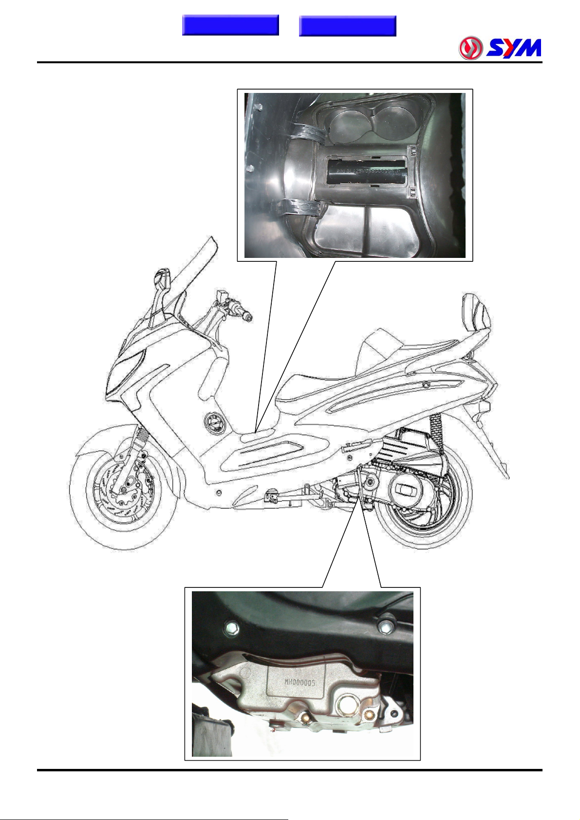
Serial Number
Page 6
Homepage
Contents
Symbols and Marks····························1-1
General Safety····································1-2
Before Servicing·································1-3
Torque Values···································· 1-12
Trouble Diagnosis······························ 1-14
Lubrication Points ····························· 1-18
1. General Information
Specifications·····································1-9
Symbols and Marks
Symbols and marks are used in this manual to indicate what and where the special service is needed. If
supplemental information is needed for these symbols and marks, explanations will be added in the text
instead of using the symbols or marks.
Warning
Caution
Means that serious injury or loss of life may happen if procedures are not
correctly followed.
Means that equipment damages may result if procedures are not followed.
Limits to use SAE 10W-30 API SG class oil. Warranty will not cover the
1
Engine oil
Grease King Mate G-3 is recommended.
Gear oil
Locking sealant
Oil seal
Renew
Brake fluid
Special tools
Correct
Wrong
damage that caused by not apply with the limited engine oil.
(Recommended oil: KING MATE G-3 oil)
King Mate gear oil serials are recommended. (Bramax HYPOID GEAR OIL
# 140)
Apply sealant; medium strength sealant should be used unless otherwise
specified.
Apply with lubricant.。
Replace with a new part before installation.
Use recommended brake fluid DOT3 or WELLRUN brake fluid.
Special tools
Meaning correct installation.
Meaning wrong installation.
Indication Indication of components.
Directions
Indicates position and operation directions
Components assembly directions each other.
Indicates where the bolt installation direction, --- means that bolt cross
through the component (invisibility).
1-1
Page 7
To this chapter contents
1. General Information
General Safety
Carbon Monoxide
Before you start the engine, make sure the place
is well ventilated. Never start the engine in an
unventilated place. If you have to start the engine
in an unventilated place, an exhaust fume
extractor is needed.
Caution
Exhaust fume contains toxic gas which may
cause one to lose consciousness and even result
in loss of life.
Gasoline
Gasoline is a low ignition point and explosive
material. Work in a well-ventilated place, no flame
or spark should be allowed in the work place or
where gasoline is being stored.
Caution
Gasoline is highly flammable, and may explode
under some conditions, keep it away from the
children.
Used Engine Oil
Caution
Prolonged contact with the used engine oil (or
transmission oil) may cause skin cancer although
it might not be verified yet. We recommend that
you wash your hands with soap right after
contacting. Keep the used oil beyond reach of the
children.
Hot Components
Caution
Components of the engine and exhaust system
can be extremely hot after engine running. They
remain very hot even after the engine has been
stopped for a period of time. Before performing
service work on these parts, wear the heat
insulation gloves or wait until the temperature
drops.
Battery
Caution
‧ Battery emits explosive gases; flame is strictly
prohibited. Keep the place well ventilated
when the battery is being charged.
‧ Battery contains sulfuric acid (electrolyte)
which can cause serious burns, be careful not
to spill it on your skin or eyes. If you get
battery fluid on your skin, flush it off with water
immediately. If you get battery fluid in your
eyes, flush it off immediately with water and
go to hospital to see an ophthalmologist
doctor.
‧ If you swallow the battery fluid by mistake,
drink a lot of water or milk, and take some
laxative such as Epsom salts or vegetable oil
and then go to see a doctor.
‧ Keep the battery and battery fluid beyond
reach of the children.
Brake Shoes
Do not use compressed air or brush to clean the
components of the brake system. Use a vacuum
cleaner or the equivalent to avoid dust drifting in
the air.
Caution
Inhaling brake shoes dust may cause disease or
even cancer of the respiratory system.
Brake Fluid
Caution
Brake fluid spilled on painted, plastic, or rubber
parts may cause damage to the parts. Place a
clean towel on the top of the parts for protection
when servicing the brake system. Keep the brake
fluid beyond reach of the children.
1-2
Page 8
To this chapter contents
Before Servicing
y Always use SANYANG genuine parts and
recommended oil. Using improper parts may
cause damage to or destruction of the vehicle.
y Special tools are designed for removal and
installation of component parts without
damaging them. Using wrong tools may result in
parts damage.
y When servicing this vehicle, use only metric
tools. Metric bolts, nuts, and screws are not
interchangeable with the Britain system, using
wrong tools and fasteners may damage this
vehicle.
1. General Information
y Never bend or twist control cables to avoid
unsmooth control and premature worn out.
y Rubber parts may become deteriorated when
old, and be damaged by solvent and oil easily.
Check these parts before installation to make
sure that they are in good condition, replace if
necessary.
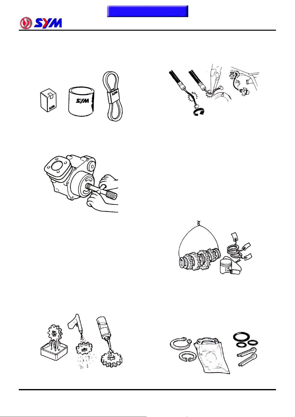
y When loosening a component which has
different sized fasteners, operate with a
diagonal pattern and work from inside out.
Loosen the small fasteners first. If the bigger
ones are loosen first, small fasteners may
receive too much stress.
y Store complex components such as
transmission parts in the proper assemble order
and tie them together with a wire for ease of
installation later.
y Clean the outside of the parts or the cover
before removing it from the vehicle. Otherwise,
dirt and deposit accumulated on the part's
surface may fall into the engine, chassis, or
brake system to cause damage.
y Wash and clean parts with high flash point
solvent, and then blow dry with compressed air.
Pay special attention to O-rings or oil seals
because most of the cleaning agents have bad
effect on them.
y Note the reassemble position of the important
components before disassembling them to
ensure they will be reassembled in correct
dimensions (depth, distance or position).
y Components not to be reused should be
replaced when disassembled including gaskets
metal seal rings, O-rings, oil seals, snap rings,
and split pins.
1-3
Page 9

To this chapter contents
1. General Information
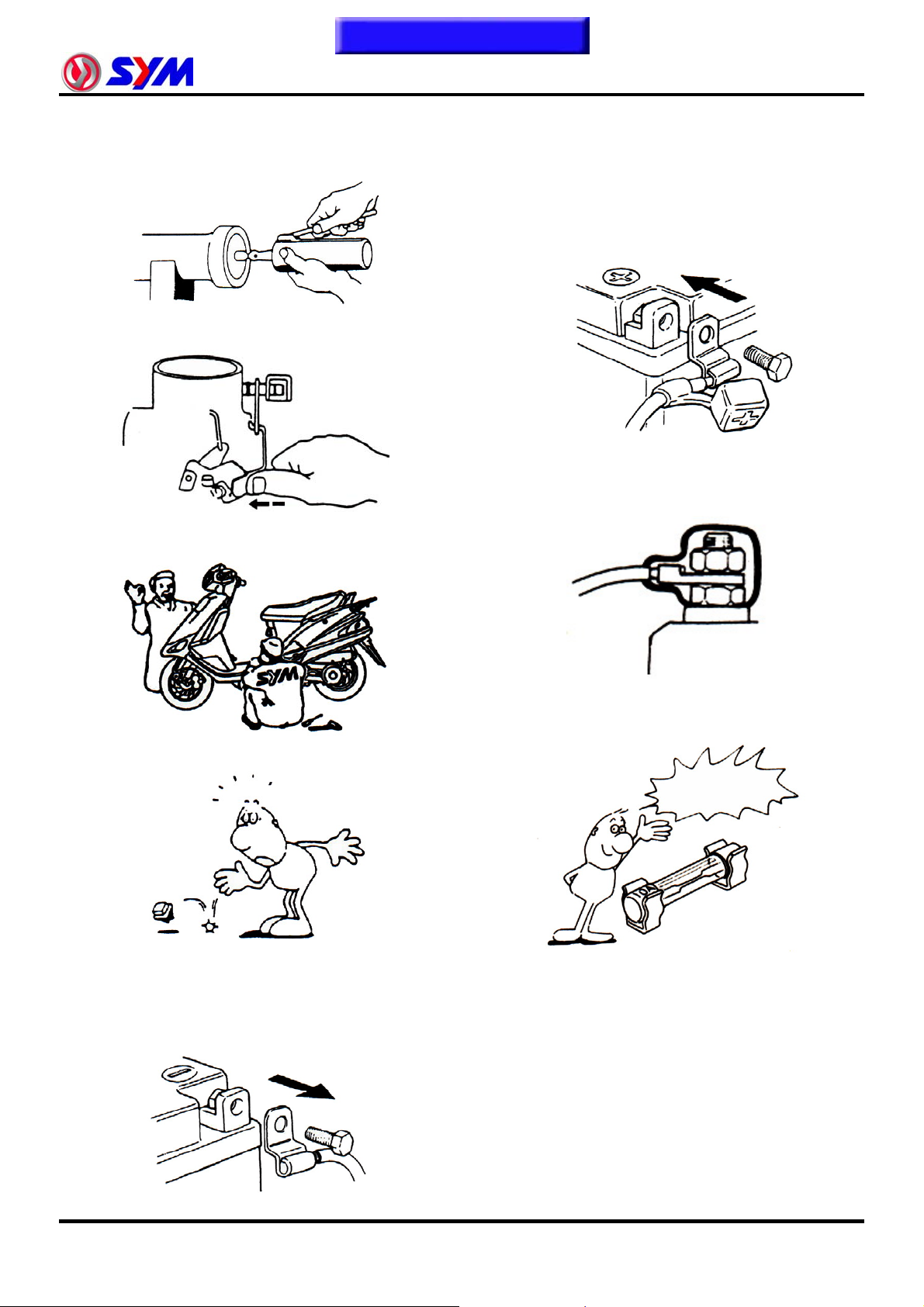
y The length of bolts and screws for assemblies,
cover plates or boxes is different from one
another, be sure they are correctly installed. In
case of confusion, Insert the bolt into the hole to
compare its length with other bolts, if its length
out side the hole is the same with other bolts, it
is a correct bolt. Bolts for the same assembly
should have the same length.
y Tighten assemblies with different dimension
fasteners as follows: Tighten all the fasteners
with fingers, then tighten the big ones with
special tool first diagonally from inside toward
outside, important components should be
tightened 2 to 3 times with appropriate
increments to avoid warp unless otherwise
indicated. Bolts and fasteners should be kept
clean and dry. Do not apply oil to the threads.
y Remove residues of the old gasket or sealant
before reinstallation, grind with a grindstone if
the contact surface has any damage.
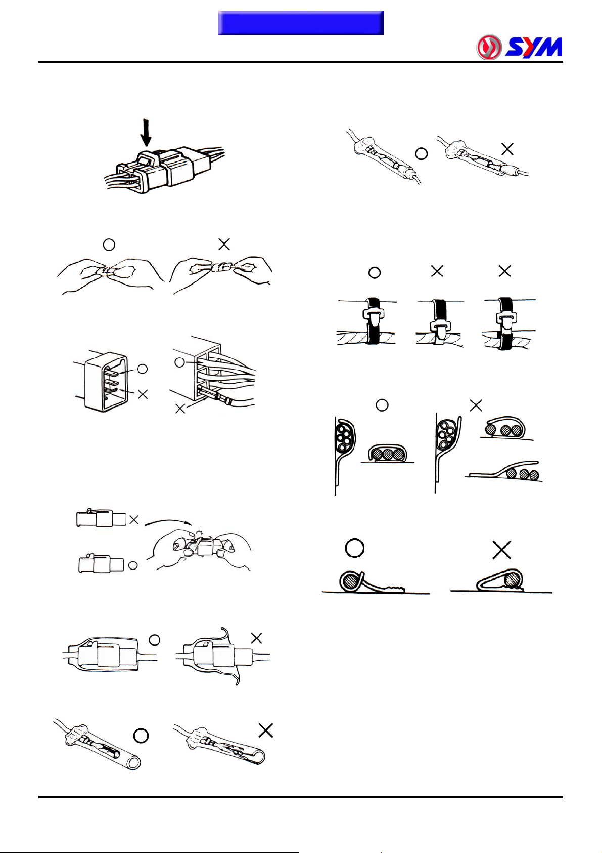
y The ends of rubber hoses (for fuel, vacuum, or
coolant) should be pushed as far as they can go
to their connections so that there is enough
room below the enlarged ends for tightening the
clamps.
Groove
Clamp
Connector
y Rubber and plastic boots should be properly
reinstalled to the original correct positions as
designed.
y When oil seal is installed, fill the groove with
grease, install the oil seal with the name of the
manufacturer facing outside, and check the
shaft on which the oil seal is to be installed for
smoothness and for burrs that may damage the
oil seal.
Manufacturer's name
1-4
Boots
y The tool should be pressed against two (inner
and outer) bearing races when removing a ball
bearing. Damage may result if the tool is
pressed against only one race (either inner race
or outer race). In this case, the bearing should
be replaced. To avoid damaging the bearing,
use equal force on both races.
Both of these examples can result in
bearing damage.
Page 10
To this chapter contents
y Lubricate the rotation face with specified
lubricant on the lubrication points before
assembling.
y Check if positions and operation for installed
parts is in correct and properly.
y Make sure service safety each other when
conducting by two persons.
1. General Information
y After service completed, make sure all
connection points is secured.
Battery positive (+) cable should be connected
firstly.
y And the two posts of battery have to be greased
after connected the cables.
y Make sure that the battery post caps are
located in properly after the battery posts had
been serviced.
y Note that do not let parts fall down.
y Before battery removal operation, it has to
remove the battery negative (-) cable firstly.
Notre tools like open-end wrench do not contact
with body to prevent from circuit short and
create spark.
y If fuse burned, it has to find out the cause and
solved it. And then replace with specified
capacity fuse.
Capacity
verification
1-5
Page 11
To this chapter contents
1. General Information
y When separating a connector, it locker has to
be unlocked firstly. Then, conduct the service
operation.
y Do not pull the wires as removing a connector
or wires. Hold the connector body.
y Make sure if the connector pins are bent,
extruded or loosen.
y Insert the terminal completely.
Check if the terminal is covered by the boot.
Do not let boot open facing up.
y Secure wires and wire harnesses to the frame
with respective wire bands at the designated
locations. Tighten the bands so that only the
insulated surfaces contact the wires or wire
harnesses.
y Insert the connector completely.
If there are two lockers on two connector sides,
make sure the lockers are locked in properly.
Check if any wire loose.
y Check if the connector is covered by the twin
connector boot completely and secured
properly.
y Wire band and wire harness have to be
clamped secured properly.
y Do not squeeze wires against the weld or its
clamp.
y Before terminal connection, check if the boot is
crack or the terminal is loose.
1-6
Page 12
To this chapter contents
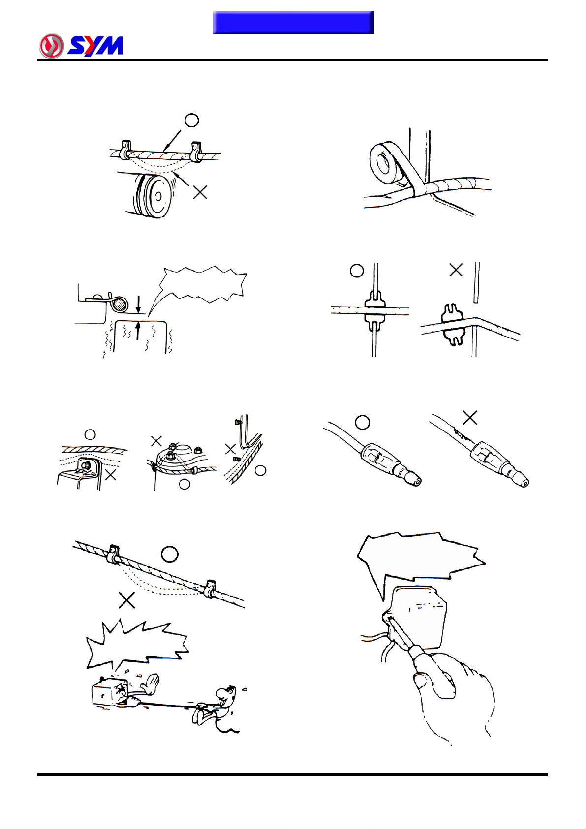
y Do not let the wire harness contact with rotating,
moving or vibrating components as routing the
harness.
y Keep wire harnesses far away from the hot
parts.
Never Touch
1. General Information
y Protect wires or wire harnesses with electrical
tape or tube if they contact a sharp edge or
corner. Thoroughly clean the surface where
tape is to be applied.
y Secure the rubber boot firmly as applying it on
wire harness.
y Route wire harnesses to avoid sharp edges or
corners and also avoid the projected ends of
bolts and screws.
y Route harnesses so that they neither pull too
tight nor have excessive slack.
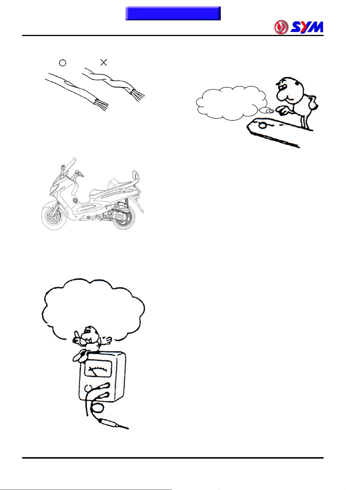
y Never use wires or harnesses which insulation
has been broken. Wrap electrical tape around
the damaged parts or replace them.
y Never clamp or squeeze the wire harness as
installing other components.
Never clamp or
squeeze the wire
harness
Never too tight
1-7
Page 13
To this chapter contents
1. General Information
y Do not let the wire harness been twisted as
installation.
y Wire harnesses routed along the handlebar
should not be pulled too tight or have excessive
slack, be rubbed against or interfere with
adjacent or surrounding parts in all steering
positions.
y With sand paper to clean rust on connector
pins/terminals if found. And then conduct
connection operation later.
Clean rust
y Before operating a test instrument, operator
should read the operation manual of the
instrument. And then, conduct test in
accordance with the instruction.
Do you know how to set the
instrument to its
measurement position and
the insert locations of its
two probes?
1-8
Page 14
To this chapter contents
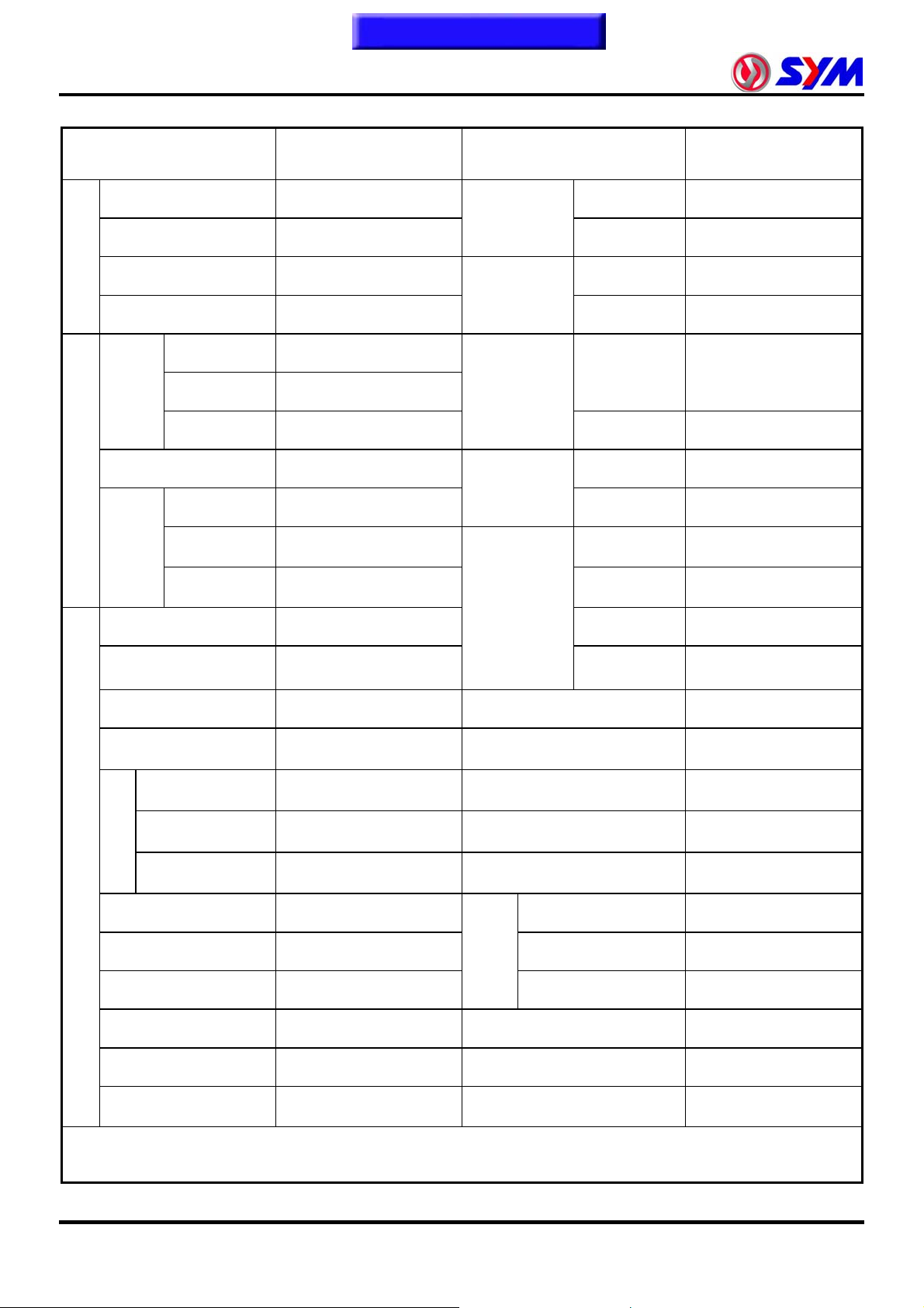
Specifications
MAKER SANYANG MODEL LM25W5-6/7
Overall Length
Overall Width
Dimension
Weight
Overall Height
Wheel Base
Front
Curb
Weight
Passengers/Weight
Rear
Total
Front
2165 mm
870 mm
1395 mm
1495 mm
79 kg
111 kg
190 kg
Two / 150 kg
134 kg
Suspension
System
Tire
Specifications
Brake System
Performance
1. General Information
Front
Rear
Front
Rear
Front
Rear
Max. Speed
Climb Ability
TELESCOPIC FORK
UNlT SWING
110 / 90-13 56P
130 / 70-13 57P
DISK (ø 240 mm)
DISK (ø 220 mm)
128 km/hr
<27°
Total
Weight
Type
Installation and
arrangement
Fuel
Cycle/ Cooling
Bore
Stroke
Cylinder
Number/Arrange
Engine
Displacement
Compression Ratio
ment
Max. HP
Rear
Total
206 kg
340 kg
4-STROKE ENGINE
Vertical, below center,
incline 80°
Above 92 unleaded
4-stroke/
Liquid-cooled
71 mm
63.3 mm
SINGLE CYLINDER
250.6 cc
10.5 : 1
23.4 ps / 8000 rpm
Primary
Reduction
Secondary
Reduction
Speedometer
Exhaust Pipe Position and
Direction
Lubrication System
n
Exhaust
Concentratio
Reduction
Clutch
Transmission
Horn
Muffler
CO
HC
NOx
Belt
Gear
Centrifugal, dry type
CVT
0 ~ 160 km/hr
<110 dB/A
Expansion & Pulse
Type
Right side, and
Backward
Forced circulation &
splashing
<2.0 g/km
<0.3 g/km
<0.15 g/km
Max. Torque
Ignition
Starting System
2.3 kg-m / 5500 rpm
Full transistor ignition
Electrical starter
Catalytic reaction control
E.E.C. -
P.C.V. √
system
√
1-9
Page 15
To this chapter contents
1. General Information
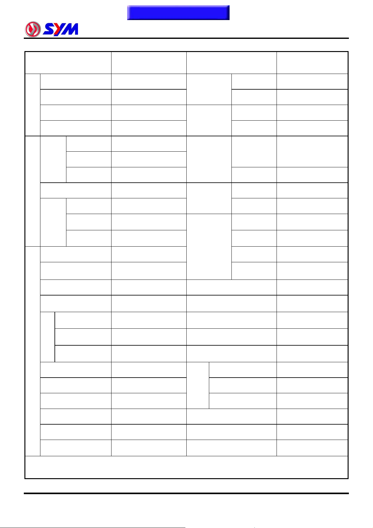
Specifications
MAKER SANYANG MODEL
Overall Length
Overall Width
Dimension
Weight
Overall Height
Wheel Base
Front
Curb
Weight
Passengers/Weight
Rear
Total
Front
Two / 150 kg
2165 mm
870 mm
1395 mm
1495 mm
79 kg
111 kg
190 kg
134 kg
Suspension
System
Tire
Specifications
Brake System
Performance
Front
Rear
Front
Rear
Front
Rear
Max. Speed
Climb Ability
LM25W5-P
LM25W7-7
TELESCOPIC FORK
UNlT SWING
110 / 90-13 56P
130 / 70-13 57P
DISK (ø 240 mm)
DISK (ø 220 mm)
128 km/hr
<27°
Total
Weight
Type
Installation and
arrangement
Fuel
Cycle/ Cooling
Bore
Stroke
Cylinder
Number/Arrange
Engine
Displacement
Compression Ratio
ment
Max. HP
Rear
Total
206 kg
340 kg
4-STROKE ENGINE
Vertical, below center,
incline 80°
Above 92 unleaded
4-stroke/
Liquid-cooled
71 mm
63 mm
SINGLE CYLINDER
249.4 cc
10.5 : 1
23.4 ps / 8000 rpm
Primary
Reduction
Secondary
Reduction
Speedometer
Exhaust Pipe Position and
Direction
Lubrication System
n
Exhaust
Concentratio
Reduction
Clutch
Transmission
Horn
Muffler
CO
HC
NOx
Belt
Gear
Centrifugal, dry type
CVT
0 ~ 160 km/hr
93~112 dB/A
Expansion & Pulse
Type
Right side, and
Backward
Forced circulation &
splashing
<2.0 g/km
<0.3 g/km
<0.15 g/km
1-10
Max. Torque
Ignition
Starting System
2.3 kg-m / 5500 rpm
Full transistor ignition
Electrical starter
E.E.C. -
P.C.V. √
Catalytic reaction control
system
√
Page 16
To this chapter contents
Specifications
MAKER SANYANG MODEL LM30W-6/T
Overall Length
Overall Width
Dimension
Weight
Overall Height
Wheel Base
Front
Curb
Weight
Passengers/Weight
Rear
Total
Front
2165 mm
870 mm
1395 mm
1495 mm
79 kg
111 kg
190 kg
Two / 150 kg
134 kg
Suspension
System
Tire
Specifications
Brake System
Performance
1. General Information
Front
Rear
Front
Rear
Front
Rear
Max. Speed
Climb Ability
TELESCOPIC FORK
UNlT SWING
110 / 90-13 56P
130 / 70-13 57P
DISK (ø 240 mm)
DISK (ø 220 mm)
128 km/hr
<27°
Total
Weight
Type
Installation and
arrangement
Fuel
Cycle/ Cooling
Bore
Stroke
Cylinder
Number/Arrange
Engine
Displacement
Compression Ratio
ment
Max. HP
Rear
Total
206 kg
340 kg
4-STROKE ENGINE
Vertical, below center,
incline 80°
Above 92 unleaded
4-stroke/
Liquid-cooled
73 mm
63 mm
SINGLE CYLINDER
263.7 cc
10.1 : 1
23.3 ps / 7500 rpm
Primary
Reduction
Secondary
Reduction
Speedometer
Exhaust Pipe Position and
Direction
Lubrication System
n
Exhaust
Concentratio
Reduction
Clutch
Transmission
Horn
Muffler
CO
HC
NOx
Belt
Gear
Centrifugal, dry type
CVT
0 ~ 160 km/hr
93~112 dB/A
Expansion & Pulse
Type
Right side, and
Backward
Forced circulation &
splashing
<2.0 g/km
<0.3 g/km
<0.15 g/km
Max. Torque
Ignition
Starting System
2.5 kg-m / 5500 rpm
Full transistor ignition
Electrical starter
Catalytic reaction control
E.E.C. -
P.C.V. √
system
√
1-11
Page 17
To this chapter contents
1. General Information
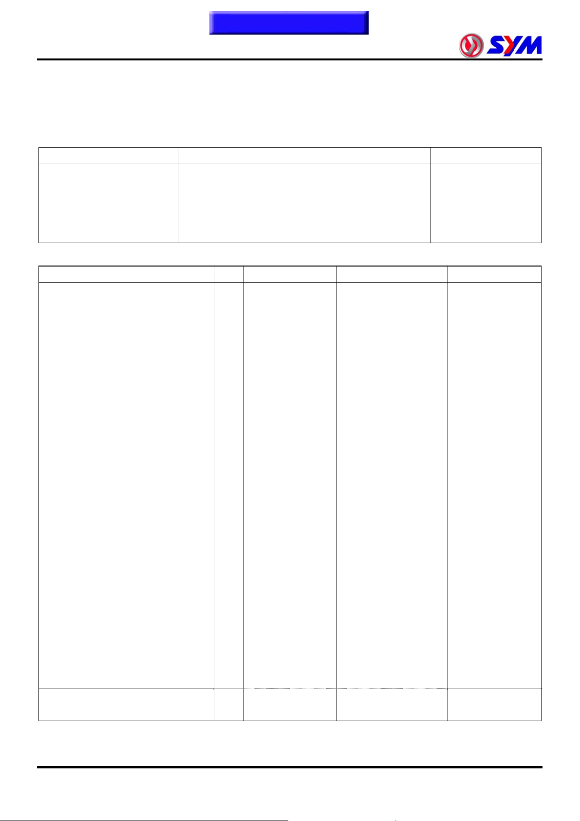
Torque Values
The torque values listed in below are for more important tightening torque values. Please see standard
values for those not listed in the table.
Standard Torque Values for Reference
Type Tighten Torque Type Tighten Torque
5 mm bolt、nut
6 mm bolt、nut
8 mm bolt、nut
10 mm bolt、nut
12 mm bolt、nut
Engine Torque Values
Item Q’ty Thread Dia. (mm) Torque Value(kgf-m) Remarks
Cylinder stud bolt 4 10 1.0~1.4
Cylinder head nut 4 8 3.6~4.0
Cylinder head right bolt 2 8 2.0~2.4
Cylinder head side cover bolt 2 6 1.0~1.4
Cylinder head cover bolt 4 6 1.0~1.4
Cylinder head stud bolt (inlet pipe) 2 6 1.0~1.4
Cylinder head stud bolt (EX. pipe) 2 8 2.4~3.0
Air inject pipe bolt 4 6 1.0~1.4
Air inject reed valve bolt 2 3 0.07~0.09
Tappet adjustment screw nut 4 5 0.7~1.1 Apply oil to thread
Spark plug 1 10 1.0~1.2
Camshaft Chain Tensioner bolt 2 6 1.0~1.4
Carburetor insulator bolt 2 6 0.7~1.1
Oil pump screw 2 3 0.1~0.3
Water pump impeller 1 7 1.0~1.4
Engine left cover bolt 9 6 1.1~1.5
Engine oil draining bolt 1 12 3.5~4.5
Engine oil strainer cap 1 30 1.3~1.7
Mission draining bolt 1 8 0.8~1.2
Mission filling bolt 1 10 1.0~1.4
Clutch driving plate nut 1 28 5.0~6.0
Clutch outer nut 1 14 5.0~6.0
Drive face nut 1 14 8.5~10.5
ACG. Flywheel nut 1 14 5.0~6.0
Crankcase bolt 7 6 0.8~1.2
Mission case bolt 7 8 2.6~3.0
Muffler mounting bolt 3 10 3.2 ~3.8
Muffler mounting nut 2 8 1.0 ~1.2
0.45~0.6kgf-m 5 mm screw 0.35~0.5kgf-m
0.8~1.2kgf-m
1.8~2.5kgf-m
3.0~4.0kgf-m
5.0~6.0kgf-m
6 mm screw、SH nut
6 mm bolt、nut
8 mm bolt、nut
10 mm bolt、nut
0.7~ 1.1kgf-m
1.0 ~1.4kgf-m
2.4 ~3.0kgf-m
3.5~4.5kgf-m
1-12
Page 18
To this chapter contents
1. General Information
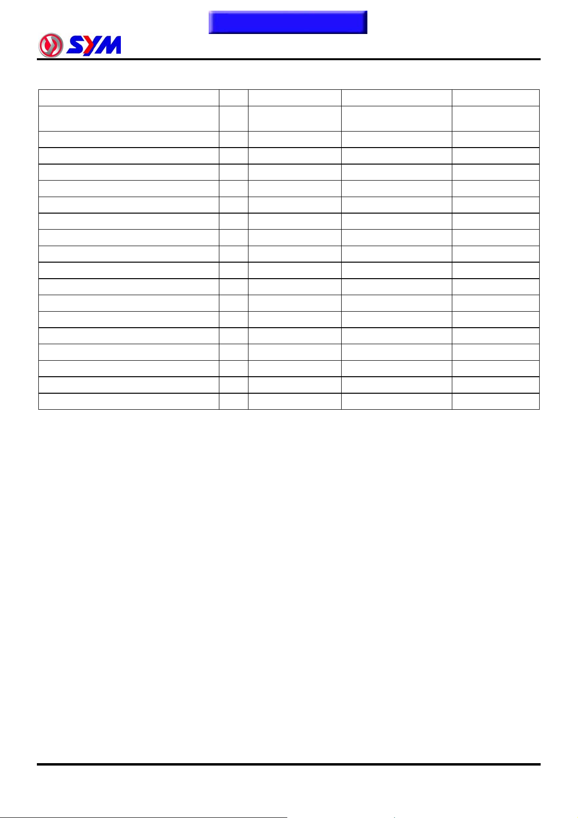
Frame Torque Values
Item Q’ty Thread Dia. (mm) Torque Value (Kg-m) Remarks
Mounting bolt for steering handle
post
Lock nut for steering stem 1 BC1 1.0~2.0
Steering top cone race 1 BC1 2.0~3.0
Front wheel axle nut 1 12 5.0~7.0
Rear wheel axle nut 1 16 11.0~13.0
Front cushion mounting bolt 4 10 3.5~4.5
Rear cushion upper connection bolt 1 10 3.5~4.5
Rear cushion under connection bolt 1 8 2.4~3.0
Rear fork mounting bolt 2 10 4.0~5.0
Brake hose bolt 2 10 3.0~4.0
Brake air-bleeding valve 1 6 0.8~1.0
Front brake disc mounting bolt 5 8 4.0~4.5
Rear brake disc mounting bolt 5 8 4.0~4.5
Brake clipper mounting bolt 2 8 2.9~3.5
Engine hanger link bolt 2 12 7.5~9.5 On frame side
Engine hanger link nut 1 12 7.5~9.5 On engine side
Main standard nut 1 10 4.0~5.0
Air cleaner bolts 2 6 1.0~1.4
1 10 4.0~5.0
1-13
Page 19
To this chapter contents
r
1. General Information
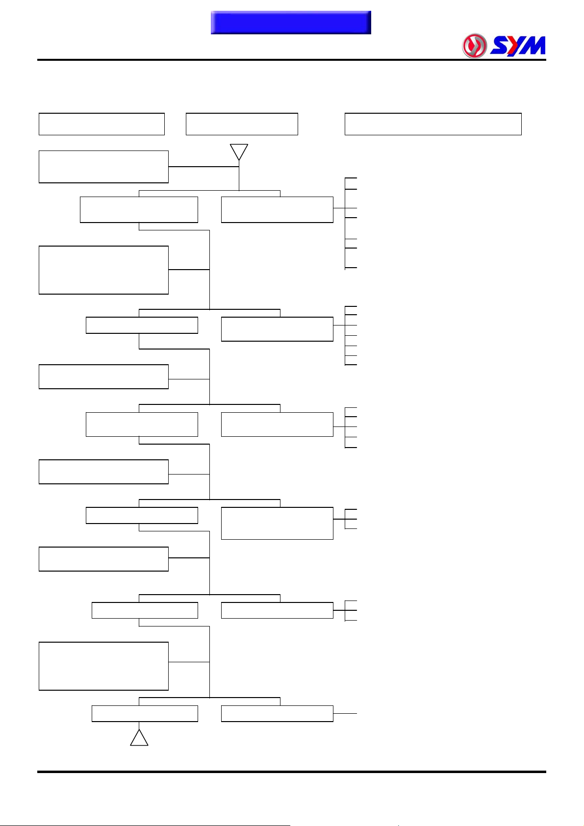
Trouble Diagnosis
A. Engine hard to start or can not be started
Check and adjustment Failure condition Possible causes
Loosen carburetor drain bolt
to check if there is gasoline
inside the carbureto
Fuel supplied tom
carburetor sufficient
Remove spark plug, install it
into spark plug cap, and
perform a spark test against
engine ground.
Check if sparks Weak sparks, no spark
Perform cylinder
compression pressure test.
No fuel is supplied to
carburetor
at all
1. No fuel in fuel tank
2. Check if the pipes, fuel tank to carburetor
and intake vacuum, are clogged.
3. Float valve clogged
4. Lines in fuel tank evaporation system
clogged
5. Malfunction of fuel pump
6. Loosen or damaged fuel pump vacuum
hose
7. Fuel filter clogged
1. Malfunction of spark plug
2. Spark plug foul
3. Malfunction of CDI set
4. Malfunction of AC generator
5. Ignition coil is in open or short circuit
6. Ignition coil leads open or short circuit
7. Malfunction of main switch
Cylinder compression
pressure normal
Re-start by following the
starting procedures
No ignition There are some signs of
Remove the spark plug again
and check it.
Dry spark plug Wet spark plug
Remove carburetor after 30
minutes and connect a hose
onto fuel rich circuit. Then
blow the hose with air
Low compression
pressure or no pressure
ignition, nut engine can
not be started
1. Piston ring seized
2. Malfunction of cylinder valves
3. Worn cylinder and piston ring
4. Cylinder gasket leak
5. Sand hole in compression parts
1. Malfunction of throttle valve operation
2. Air sucked into intake manifold
3. Incorrect ignition timing
1. Fuel level in carburetor too high
2. Malfunction of throttle valve operation
3. Throttle valve opening too wide
1-14
Blowing in normal Blowing clogged
1. Malfunction of automatic by- starter
Page 20
To this chapter contents
1. General Information
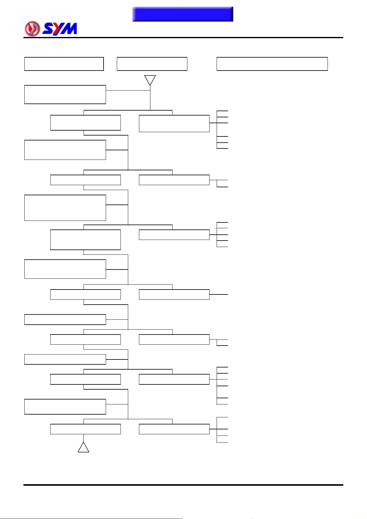
B. Engine run sluggish (Speed does not pick up, lack of power)
Check and adjustment Fault condition Probable causes
Try gradual acceleration and
check engine speed
Check ignition timing
(Using ignition lamp)
Engine speed can be
increased.
Ignition timing correct Incorrect ignition timing
Check cylinder compression
pressure (using compression
pressure gauge)
Compression pressure
correct
Engine speed can not be
increased.
No compression pressure
1. Air cleaner clogged
2. Poor fuel supply
3. Lines in fuel tank evaporation system
clogged
4. Exhaust pipe clogged
5. Fuel level too low in carburetor
6. Fuel nozzle clogged in carburetor.
1. Malfunction of CDI
2. Malfunction of AC alternator
1. Cylinder & piston ring worn out
2. Cylinder gasket leaked
3. Sand hole in compression parts
4. Valve deterioration
5. Seized piston ring
Check if carburetor jet is
clogged
No clogged Clogged
Remove spark plug
No foul or discoloration Fouled and discoloration
Check if engine over heat
Normal Engine overheat
Continually drive in
acceleration or high speed
No knock Knock
1. Remove foreign
1. Remove dirt
2. Incorrect spark plug heat range
1. Piston and cylinder worn out
2. Lean mixture
3. Poor fuel quality
4. Too much carbon deposited in
combustion chamber
5. Ignition timing too advanced
6. Poor circuit on the cooling system
1. Too much carbon deposited in
combustion chamber
2. Lean mixture
3. Poor fuel quality
4. Ignition timing too advanced
1-15
Page 21
To this chapter contents
1. General Information
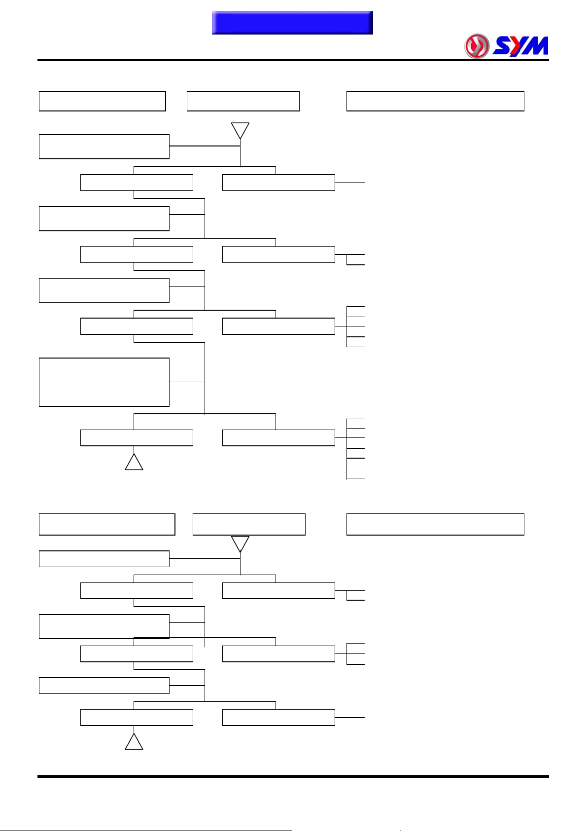
C. Engine runs sluggish (especially in low speed and idling)
Check and adjustment Fault condition Probable causes
Check ignition timing
(Using ignition lamp)
Adjust the air screw of
carburetor
Normal Abnormal
Good Poor
Air sucked through
carburetor gasket
No air sucked Air sucked
Remove spark plug, install
spark plug into spark plug
cap and perform spark test
against engine ground
1. Incorrect ignition timing (malfunction
of CDI or AC alternator)
1. Rich mixture (loosen the screw)
2. Lean mixture (tighten the screw)
1. Poor heat insulation gasket
2. Carburetor lock loose
3. Poor intake gasket
4. Poor carburetor O-ring
5. Vacuum hose crack
Good spark Poor
D. Engine runs sluggish (High speed)
Check and adjustment
Check ignition timing
Normal Abnormal
Check for fuel supplying
system in automatic fuel cup
Good Poor
Check if carburetor clogged
Fault condition Probable causes
1. Spark plug fouled
2. Malfunction of CDI
3. Malfunction of AC generator
4. Malfunction of ignition coil
5. Open or short circuit in spark plug
leads
6. Malfunction of main switch
1. Malfunction of CDI
2. Malfunction of AC alternator
1. Insufficient fuel in fuel tank
2. Fuel filter clogged
3. Restricted fuel tank vent
1-16
No clogged Clogged
1. Cleaning
Page 22
To this chapter contents
1. General Information
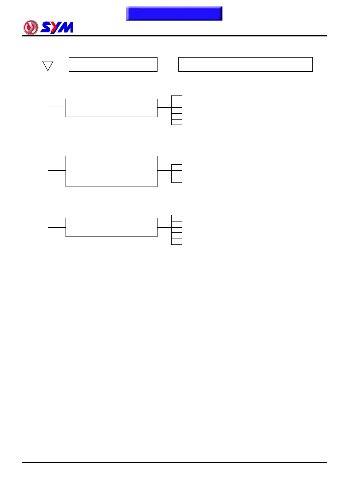
E. Clutch, Driving And Driving Pulley
FAULT CONDITIONS
Engine can be started but
motorcycle can not be moved.
Engine running and misfire as
motorcycle initial forward moving or
jumping suddenly (rear wheel
rotating as engine in running)
PROBABLE CAUSES
1. Driving belt worn out or deformation
2. Driving disk damaged
3. Driving pulley spring broken
4. Clutch ling broken
5. Driving slide-shaft gear groove broken
6. Transmission gear damaged
1. Clutch ling spring broken
2. Clutch outer cover stickled with clutch balance
weights
3. Connection parts in clutch and shaft worn out or
burned
1. Driving belt worn out or deformation
Poor initial driving
(Poor climbing performance)
2. Balance weight roller worn out
3. Driving sliding gear shaft worn out
4. Driving disk spring deformation
5. Driving sliding gear shaft worn out
6. Greased in driving belt and sliding gear.
1-17
Page 23
To this chapter contents
1. General Information
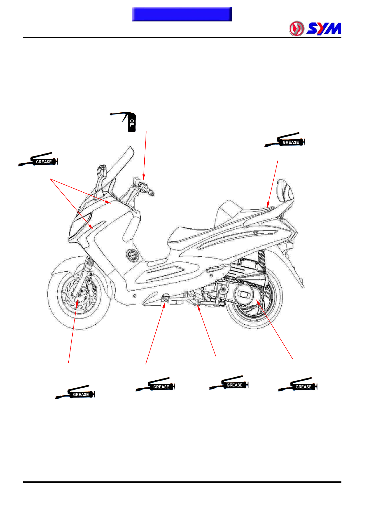
Lubrication Points
Steering shaft bearing
Acceleration cable/
Front & rear brake lever pivot
Seat locker
1-18
Speedometer gear/
front wheel bearing
Side stand shaft
Main stand shaft
Clutch bearing
Page 24
Home page
Contents
Precautions in Operation···················· 2-1
Periodical Maintenance Schedule······ 2-2
Engine Oil············································· 2-3
Engine Oil Strainer Clean···················· 2-3
Gear Oil················································· 2-4
Fuel Lines / Cable································ 2-4
Air Cleaner ··········································· 2-5
P.C.V. System ······································ 2-6
Valve Clearance··································· 2-6
Spark Plug············································ 2-7
Drive Belt··············································2-8
Steering Handle Top Bearing·············· 2-9
Cushion ················································2-9
Disk Brake System·······························2-10
Brake Light Switch / Start Switch·······2-12
Headlight Distance Adjustment·········· 2-12
Wheel / Tire···········································2-12
Battery ··················································2-13
Nuts, Bolts Tightness··························2-13
Special Tools List ································ 2-14
2. Maintenance Information
Cylinder Compression Pressure········ 2-8
Precautions in Operation
Model
Fuel Tank Capacity 12,000 c.c.
capacity 1,400 c.c.
Engine Oil
change 1,200 c.c.
LM25W5-6/7/P
LM25W7-7
2
LM30W-6/T
Transmission
Gear oil
Clearance of throttle valve 2~6 mm
Spark plug CR8E (gap:0.6~0.7 mm)
Timing advance idle speed BTDC 10º / 1,650 rpm
Full timing advanced BTDC 30º
Idling speed 1,650±100 rpm
Cylinder compression pressure 12 ± 2 kgf/cm²
Valve clearance
Tire dimension Front 110/90-13 56P
Tire dimension Rear 130/70-13 57P
Tire pressure
(cold)
Battery 12V10Ah (MF battery) / YTX12-BS
Capacity of
coolant
capacity 180 c.c.
change 160 c.c.
Engine + radiator 850 c.c.
Reservoir upper 420 c.c.
IN 0.10±0.02 mm
EX 0.15±0.02 mm
single Front: 1.75 kg/cm² Rear: 2.25 kg/cm²
Load 90 Kg (full load) Front: 2.25 kg/cm² Rear: 2.5 kg/cm²
2-1
Page 25
☆
A
R
☆
R
☆
R
☆
☆
RRep
k
☆
R R
☆
p
☆
☆
A
☆
☆
g
☆
R
☆
☆
A
A A
☆
☆
p
☆
☆
p
To this chapter contents
2. Maintenance Information
Periodical Maintenance Schedule
1 Month
every
1,000KM
ICC
ICC
II
II I I I
II I I I
II I I I
II I
II I
II I I I
II I I I
II
No item
1
2
3
4
5
ir cleaner
2nd air jet leaner
Fuel filter
Oil filter
Engine oil change
6 Tire pressure
7 Battery inspection
8 Brake & free ply check
9 Steering handle chec
10 Cushion operation check
11 Every screw tightening check
12 Gear oil check for leaking
13
14
Spark plug check or change
Gear oil change
Every
300KM
CC C
RRe
15 Frame lubrication
16 Exhaust pipe
17
18
19
20
21
22
Ignition timing
emission check in Idling
Throttle operation
Engine bolt tightenin
CVT driving device(belt﹞
CVT driving device(roller)
23 Lights/electrical equipment/multi-meters
24 Main/side stands & springs
25 Fuel lines
II I I I
II I I I
II I I
III I
III I
II I I I
II I
III I
26 Shock absorbers
27 Cam chain
28
29
30
31
32
Valve clearance
Crankcase evaporative control system
Crankcase blow-by over-flow pipe
2nd air jet system
Evaporative control system
33 Lines & connections in cooling system
34 Coolant reservoir
35 Coolant
III I
I
ICC C
IIC C
II I I I
II I I I
IRe
lace
36 ECU input voltage
37 EFi sensor coupler
Code: I ~ Inspection, cleaning, and adjustment R ~ Replacement C ~ Cleaning (replaced if necessary) L ~ Lubrication
Have your motorcycle checked, adjusted, and recorded maintenance data periodically by your SYM Authorized Dealer to
maintain the motorcycle at the optimum condition
The above maintenance schedule is established by taking the monthly 1,000 kilometers as a reference which ever comes first.
Remarks: 1. These marks “ ☆” in the schedule are emission control items. According to EPA regulations, these items must be
performed normally period ica l mainte nanc e fol lo wing the use r man ual i nstruc tions . They are prohibited to be
adjusted or repaired by unauthorized people. Otherwise, SYM is no responsible for the charge.
2. Clean or replace the air cleaner element more often when the motorcycle is operated on dusty roads or in the
Heavily- polluted environment.
3. Maintenance should be performed more often if the motorcycle is frequently operated in high speed and after the
motorcycle has accumulated a higher mileage.
4. Preventive maintenance
a. Ignition system-Perform maintenance and check when continuous abnormal ignition, misfire, after-burn, overheating occur.
b. Carbon deposit removal-Remove carbon deposits in cylinder head, piston heads, exhaust system when power is obvious
lower. Than ever
c. Replace worn out pistons, cylinder head.
II
3 month
every
3,000KM
6 month
every
6,000KM
lacement for every 1,000 km
lacement for every 5,000 km
L L
I
C C
II I
Re
lacement for every 2,000 km
II I
I
1 year
every
12,000KM
2-2
Page 26

To this chapter contents
Engine Oil
Turn off engine, and park the motorcycle in flat
surface with main stand.
Check oil level with oil dipstick
So not screw the dipstick into engine as checking.
If oil level is nearly low level, fill out recommended
oil to upper level.
Oil Change
Caution
y Drain oil as engine warmed up so that make
sure oil can be drained smoothly and
completely.
Place an oil pan under the motorcycle, and
remove oil drain bolt.
After drained, make sure washer can be re-used.
Install oil drain bolt.
Torque value: 3.5~4.5kgf-m
Add oil to crankcase (oil viscosity SAE 10W-30)
Recommended using King serial oil.
Engine oil capacity:
Disassembly 1400c.c.
Replacement 1200c.c.
Install dipstick, start the engine for running several
minutes.
Turn off engine, and check oil level again.
Check if engine oil leaks.
Engine Oil Strainer Clean
Drain engine oil out.
Remove oil strainer and spring.
Clean oil strainer.
Check if O-ring can be re-used.
Install oil strainer and spring.
Install oil strainer cap.
Torque value:1.3~1.7kgf-m
2. Maintenance Information
2-3
Page 27
To this chapter contents
2. Maintenance Information
Gear Oil
Oil level inspection
Park the motorcycle on flat surface with main
stand.
Turn off the engine.
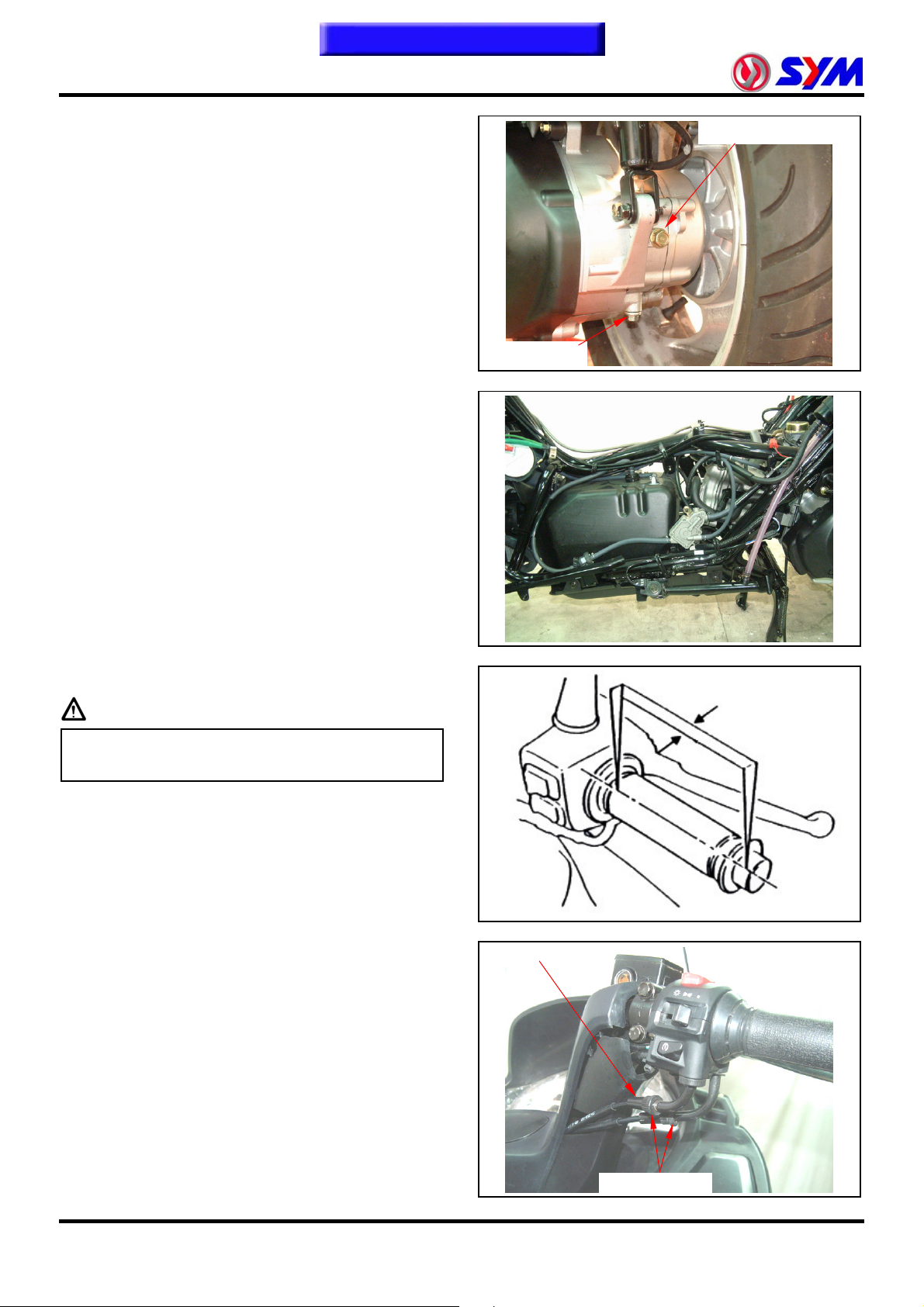
Gear Oil Change
Remove oil inspection bolt.
Remove drain plug and drain oil out.
Install the drain plug after drained.
Torque value: 0.8~1.2kgf-m
Add gear oil to specified quantity from the
inspection hole.
Install the inspection bolt.
Torque value: 1.0~1.4kgf-m
Gear Oil Quantity: 170 c.c. when replacing
Make sure that the bolt washer can be re-used,
and install the bolt.
Start engine and run engine for 2-3 minutes.
Turn off engine and make sure that oil level is in
correct level.
Make sure that no oil leaking.
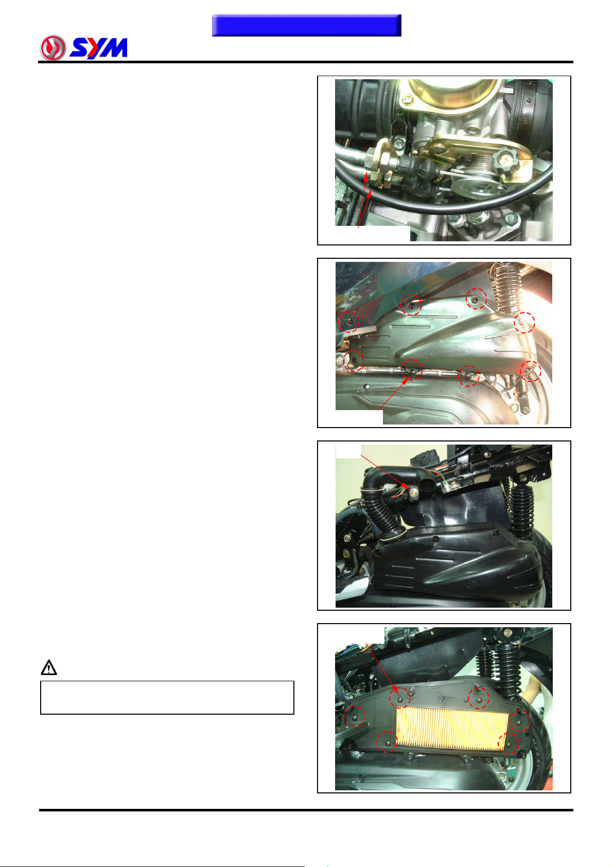
Fuel Lines / Cable
Remove luggage box.
Remove rear carrier.
Remove body covers.
Check all lines, and replace it when they are
deterioration, damage or leaking.
Warning
Drain plug
Oil inspection bolt
2~6 mm
y Gasoline is a low ignition material so any kind
of fire is strictly prohibited as dealing it.
Acceleration Operation
Have a wide open of throttle valve as handle bar in
any position and release it to let back original (full
closed) position.
Check handle bar if its operation is smooth.
Check acceleration cable and replace it if
deteriorated, twisted or damaged.
Lubricate the cable if operation is not smooth
Measure handle bar free play in its flange part.
Free play: 2~6 mm.
Adjustment can be done in either end.
Secondary adjustment is conducted from top side.
Remove rubber boot, loosen fixing nut, and then
adjust it by turning the adjustment nut.
Rubber
Adjustment nut
2-4
Page 28
To this chapter contents
Primary adjustment is conducted from bottom
side.
Loosen fixing nut, and adjust by turning the
adjustment nut.
Tighten the fixing nut, and check acceleration
operation condition.
Air Cleaner
Air Cleaner Element
Remove 8 screws from the air cleaner cover and
then remove the cover.
Remove the body cover.
Loosen bolt from the air cleaner air hose.
Remove 6 screws, and then remove the air
cleaner element.
2. Maintenance Information
Adjustment nut
8 screws
Bolt
6 screws
Caution
y The air cleaner element is made of paper so
do not soap it into water or wash it with water.
2-5
Page 29
To this chapter contents
2. Maintenance Information
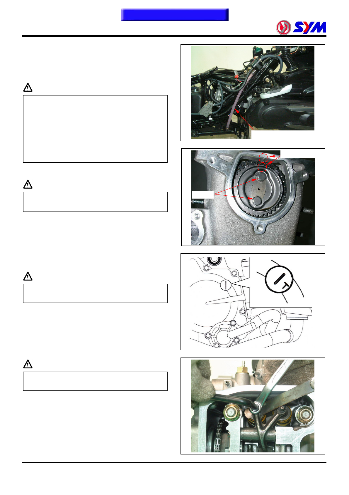
P.C.V. system
Remove the plug from lower of the breather
chamber hose.
Release the dry internal deposit.
Every 2,000 kilometers release oil
Caution
y A In releases the breather chamber hose in
the transparent section as worthy of looking
at as any deposit
y In the multi- rain or the accelerator in the
situation rides, must reduce the maintenance
traveling schedule
y In releases the breather chamber hose in the
transparent section as worthy of looking at as
any deposit
Valve Clearance
Caution
y Checks and adjustment must be performed
when the engine temperature is below 35℃.
2 bolts
Breather chamber hose
Timing mark
Remove luggage box.
Remove cylinder head cover & side cover.
Remove ignition timing hole cap located in front
upper side of engine right cover
Turn camshaft bolt in C.W. direction and let the “T”
mark on the camshaft sprocket aligns with cylinder
head mark so that piston is placed at TDC position
in compression stroke.
Caution
y Do not turn the bolt in C.C.W. direction to
prevent from camshaft bolt looseness.
Valve clearance inspection and adjustment:
Check & adjust valve clearance with feeler gauge.
Valve clearance (IN):0.10±0.02 mm.
Valve clearance (EX):0.15±0.02 mm.
Loosen fixing nut and turn the adjustment nut for
adjustment.
Caution
y Re-check the valve clearance after tightened
the fixing nut.
Special tool: Tappet adjuster
SYM-9001200-08
SYM-9001200-09
SYM-9001200-10
Special tool: Tappet adjuster wrench
SYM-9001200
2-6
Page 30
To this chapter contents
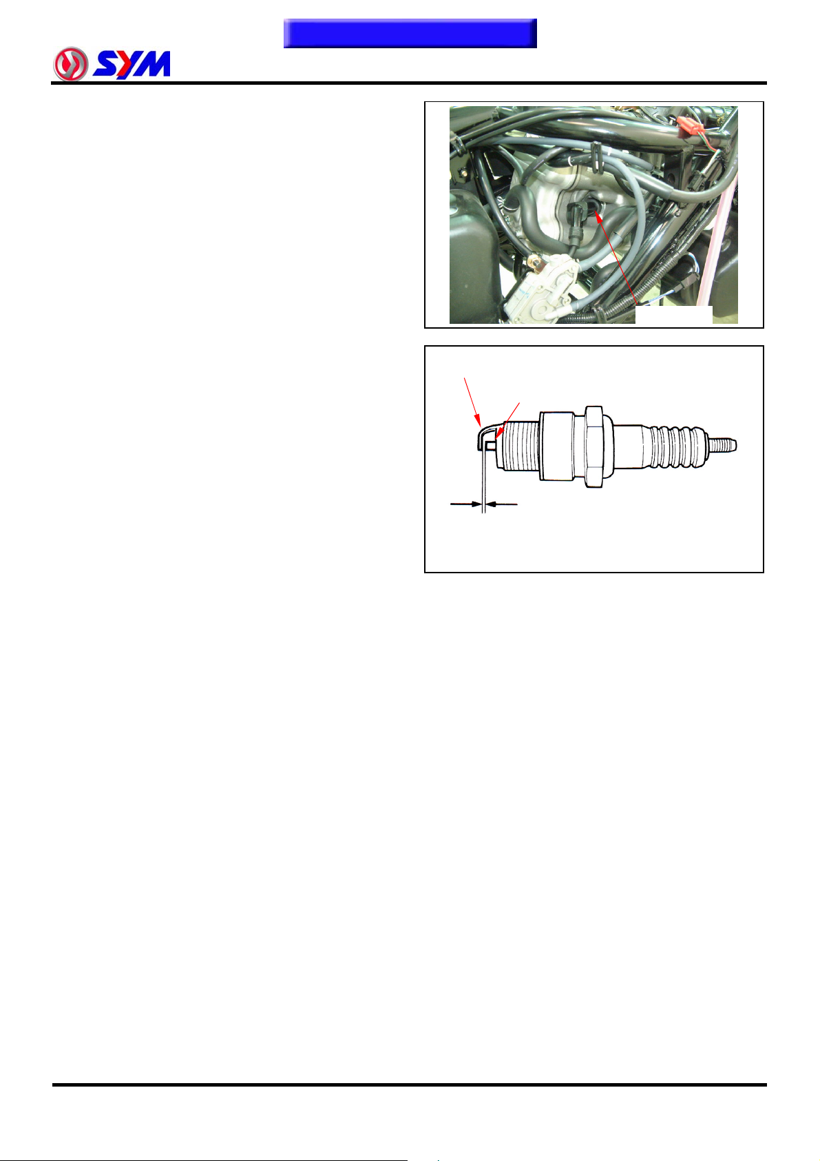
Spark Plug
Recommended spark plug: CR8E
Remove luggage box
Remove central cover.
Remove spark plug cap.
Clean dirt around the spark plug hole.
Remove spark plug.
Measure spark plug gap.
Spark plug gap: 0.6~0.7 mm
Carefully bend ground electrode of the plug to
adjust the gap if necessary.
Hold spark plug washer and install the spark plug
by screwing it.
Tighten the plug by turning 1/2 turn more with plug
socket after installed.
Tighten torque: 1.0~1.2kgf-m
Connect spark plug cap
2. Maintenance Information
Ground electrode
Central electrode
Spark plug
0.6~0.7mm
2-7
Page 31

To this chapter contents
2. Maintenance Information
Cylinder Compression Pressure
Warm up engine.
Turn off the engine.
Remove luggage box and central cover
Remove spark plug cap and spark plug.
Install compression gauge.
Full open the throttle valve, and rotate the engine
by means of starter motor.
Caution
y Rotate the engine until the reading in the
gauge no more increasing.
y Usually, the highest pressure reading will be
obtained in 4~7 seconds.
Compression pressure:12±2 Kg/cm²
Check following items if the pressure is too low:
y Incorrect valve clearance.
y Valve leaking.
y Cylinder head leaking, piston, piston ring and
cylinder worn out.
If the pressure is too high, it means carbon
deposits in combustion chamber or piston head.
Drive Belt
Remove mounting bolt located under air cleaner.
Remove the engine left side cover and the cover.
Check if the belt is crack or worn out.
Replace the belt if necessary or in accord with the
periodical maintenance schedule to replace it.
Width limit: 22.5 mm or above
Clutch Disc Wear
Run the motorcycle and increase throttle valve
opening gradually to check clutch operation.
If the motorcycle is in forward moving and shaking,
check clutch disc condition. Replace it
Spark plug cap
Teeth
Clutch lining
Compression gauge
Width
2-8
Clutch weight
Page 32

To this chapter contents
Steering Handle Top Bearing
Caution
y Check all wires and cables if they are
interfered with the rotation of steering handle
bar.
Lift the front wheel out of ground.
Turn handle from right to left alternative and check
if turning is smoothly.
If handle turning is uneven and bending, or the
handle can be operated in vertical direction, then
adjust the handle top bearing.
Cushion
Caution
y Do not ride the motorcycle with poor cushion.
y Looseness, wear or damage cushion will
make poor stability and drive-ability.
Front cushion
Press down the front cushion for several times to
check it operation.
Check if it is damage
Replace relative parts if damage found.
Tighten all nuts and bolts.
Rear Cushion
Press down the front cushion for several times to
check it operation.
Check if it is damage
Replace relative parts if damage found.
Park motorcycle with main stand.
Turn the rear wheel forcefully and check if engine
bracket bushing worn out
Replace the bushing if looseness found.
Tighten all nuts and bolts.
2. Maintenance Information
2-9
Page 33

To this chapter contents
2. Maintenance Information
Disk Brake System
Brake System Hose
Make sure the brake hoses for corrosion or
leaking oil.
Brake Fluid
Check brake fluid level in the brake fluid reservoir.
If the level is lower than the LOWER limit, add
brake fluid to UPPER limit. Also check brake
system for leaking if low brake level found
Caution
y In order to maintain brake fluid in the
reservoir in horizontal position, do not remove
the cap until handle stop.
y Do not operate the brake lever after the cap
had been removed. Otherwise, the brake
fluid will spread out if operated the lever.
y Do not mix non-compatible brake fluid
together.
Filling Out Brake Fluid
Tighten the drain valve, and add brake fluid.
Operate the brake lever so that brake fluid
contents inside the brake system hoses.
Added Brake Fluid
Add brake fluid to UPPER limit lever.
Recommended brake fluid: DOT3 or DOT4 WELL
RUN brake fluid.
Caution
y Never mix or use dirty brake fluid to prevent
from damage brake system or reducing brake
performance.
Air Bleed Operation
Connect a transparent hose to draining valve.
Hold the brake lever and open air bleeding valve.
Perform this operation alternative until there is no
air inside the brake system hoses.
Caution
Air bubble
Master cylinder cap
Diaphragm
LOWER
Brake
Fluid
Drain valve
y Before closing the air bleed valve, do not
release the brake lever.
2-10
Transparent hose
Page 34

To this chapter contents
Brake Lining Wear
The indent mark on brake lining is the wear
limitation.
Replace the brake lining if the wear limit mark
closed to the edge of brake disc.
Caution
y It is not necessary to remove brake hose when
replacing the brake lining.
Remove the brake clipper bolt, and take out the
clipper.
Caution
y Do not operate the brake lever after the clipper
removed to avoid clipping the brake lining.
Pry out the brake lining with a flat driver if lining is
clipped.
Remove 2 cotter pins
2. Maintenance Information
Lining
Brake caliper
2 bolts
Brake disk
Cotter pins
Caution
y In order to maintain brake power balance, the
brake lining must be replaced with one set.
Remove the brake pad shafts and pads.
2-11
Page 35

To this chapter contents
2. Maintenance Information
Brake Light Switch / Start Switch
The brake light switch is to light up brake lamp as
brake applied.
Make sure that starter motor can be operated only
under brake applying.
Headlight Distance Adjustment
Turn on main switch
Headlight beam adjustment. Turn the headlight
adjustment screw to adjust headlight beam high.
Caution
y To adjust the headlight beam follows related
regulations.
y Improper headlight beam adjustment will make
in coming driver dazzled or insufficient lighting.
Wheel / Tire
Stop switch
Headlight beam adjustment screws
Caution
y Tire pressure check should be done as cold
engine.。
Appointed tire pressure
Tire size Front tire Rear tire
Tire pressure as
cold engine
(Kg/cm²)
Check if tire surface is ticked with nails, stones or
other materials.
Check if front and rear tires’ pressure is in normal.
Measure tire thread depth from tire central
surface.
Replace the tire if the depth is not come with
following specification
Front tire:1.5 mm
Rear tire:2.0 mm
Load for
under 90 Kg
Full loaded 1.75 2.50
1.75 2.25
2-12
Page 36

To this chapter contents
Battery
Open the inner box lid.
Loosen screw & remove the battery cover
Battery cable remove:
1. Disconnect the cable negative terminal (-),
2. then the cable positive terminal (+)
3. Remove the battery from the motorcycle.。
If there is some rust on battery posts, clean it with
steel brush
Install the battery in the reverse procedures of
removal
Caution
y If there is rust on the posts very serious,
spray some hot water on the posts. Then,
clean it with steel brush so that can remove
rust for more easily.
y Apply some grease on the posts after rust
removed to prevent from rust again.
2. Maintenance Information
Nuts, Bolts Tightness
Perform periodical maintenance in accord with the
Periodical Maintenance Schedule.
Check if all bolts and nuts on the frame are
tightened securely.
Check all fixing pins, snap rings, hose (pipe)
clamps, and wire holders for security.
2-13
Page 37

To this chapter contents
2. Maintenance Information
Special Tools List
NAME
Left crank bearing puller
NO
SYM-9100100
R/L. crank case disassemble
NAME
tool
NO
SYM-1120000-HMA H9A
Valve cotter remove &
NAME
assembly tool
NO
SYM-1471110/20
NAME
L. Crank shaft puller
NO
SYM-1130000-HMA H9A
R. crank case bearing 6201
NAME
assembles tool
NO
SYM-9614000-HMA 6201
NAME
NAME
Tappet adjusting wrench
NO
SYM-9001200
Left crankshaft & oil seal
assembly socket.
NO
SYM-2341110- HMA RB1
NAME
Tappet adjusting
NO
SYM-9001200-08 09 10
NAME
Rocker arm shaft disassemble
NO
SYM-1445100
NAME
NO
2-14
(6204)
Bearing driver 6204
SYM-9110400
NAME
Assembly directs puller
NO
SYM-2341110
NAME
Drive shaft puller
NO
SYM-2341110- HMA RB1
Page 38

To this chapter contents
NAME
NO
Inner bearing puller
SYM-6204022
NAME
Outer bearing puller
NO
SYM-6204001
2. Maintenance Information
NAME
Handle stand nut wrench
NO
SYM-5321100
NAME
Clutch nut wrench
NO
SYM-9020200
Steering head top thread
NAME
wrench
NO
SYM-5320010
NAME
Universal holder
NO
SYM-2210100
NAME
Bearing driver HK1516
SYM-9100200-HMA RB1
NO
HK1516
NAME
AC.G. Flywheel puller
NO
SYM-3110000-HMA
NAME
Bearing puller 6205
NO
SYM-9100400 HMA RAI 6205
NAME
Air operated bearing puller
NO
SYM-9100410-400 A6205
NAME
Oil seal driver 34*52*5
NO
SYM-9125500-HMA
Right crankcase cover bearing
NAME
6201 puller
SYM-9614000-HMA RB1 6201
NO
.
2-15
Page 39

To this chapter contents
2. Maintenance Information
NAME
Bearing driver 6205
NO
SYM-9615000-6205
Drive shaft & oil seal (25*40*8)
NAME
socket
NO
SYM-9120200-HMA
NAME
Bearing puller 6303
NO
SYM-6303000-HMA H9A 6303
NAME
Bearing driver 6201
NO
SYM-9614000-6201
Water pump mechanical seal
NAME
driver
NO
SYM-1721700-H9A
(Ø30mm)
NAME
Crankcase bush puller
NO
SYM-1120310
Water pump bearing driver
NAME
6901
NO
SYM-9100100
NAME
Crankcase bush puller
NO
SYM-1120320
(Ø22mm)
Water pump oil seal driver
NAME
(inner)
NO
SYM-9120500-H9A
NAME
NO
2-16
Vacuum pressure gauge
SYM-HT07011
NAME
Fuel pressure gauge
NO
SYM-HT07010
NAME
Multi-meter
NO
SYM-HE07007-01
Page 40

To this chapter contents
NAME
NO
Cylinder pressure gauge
SYM-HT07008
2. Maintenance Information
NAME
Vehicle circuit test tool kit
NO
SYM-HE170008
NAME
Vehicle circuit test harness kit
NO
SYM-HE170008-01
NAME
NO
EFi System Diagnostic tool
2-17
Page 41

To this chapter contents
2. Maintenance Information
NOTE:
2-18
Page 42

Home page
Contents
Mechanism Diagram······························ 3-1
Precautions in Operation······················ 3-2
Troubleshooting ····································3-2
Engine Oil··············································· 3-3
0BMechanism Diagram
Press-In Lubrication
Oil Route
3. Lubrication System
Engine Oil Strainer Clean······················3-3
Oil Pump·················································3-4
Gear Oil···················································3-7
3
Valve Rocker Arm
Cam Shaft
Con-Rod
Spray Lubrication
Press-In Lubrication
Spray Lubrication
Oil Route
Rotate Direction
Oil Pump
Oil Strainer
3-1
Page 43

To this chapter contents
3. Lubrication System
1BPrecautions in Operation
General Information:
z This chapter contains maintenance operation for
the engine oil pump and gear oil replacement.
Specifications
Engine oil quantity Disassembly: 1400 c.c.
Change: 1200c.c.
Oil viscosity SAE 10W-30 (Recommended
King serial oils)
Gear oil Disassembly: 180c.c.
Change: 160c.c.
Gear oil viscosity SAE 140
(Recommended SYM Hypoid gear oils)
Unit: mm
Items Standard (mm) Limit (mm)
Inner rotor clearance 0.15 0.20
Oil pump
Clearance between outer rotor and body 0.15~0.20 0.25
Clearance between rotor side and body 0.04~0.09 0.12
Torque value
Torque value oil strainer cap 1.3~1.7kgf-m
Engine oil drain bolt 3.5~4.5kgf-m
Gear oil drain bolt 1.1~1.5kgf-m
Gear oil join bolt 1.0~1.4kgf-m
Oil pump connection screw 0.1~0.3kgf-m
2BTroubleshooting
Low engine oil level
y Oil leaking
y Valve guide or seat worn out
y Piston ring worn out
Low oil pressure
y Low engine oil level
y Clogged in oil strainer, circuits or pipes
y Oil pump damage
Dirty oil
y No oil change in periodical
y Cylinder head gasket damage
y Piston ring worn out
3-2
Page 44

To this chapter contents
3BEngine Oil
Turn off engine, and park the scooter in flat
surface with main stand.
Check oil level with oil dipstick.
So not screw the dipstick into engine as checking.
If oil level is nearly low level, fill out recommended
oil to upper level.
Oil Change
Caution
Drain oil as engine warmed up so that makes
sure oil can be drained smoothly and completely.
Place an oil pan under the scooter, and remove oil
drain bolt.
After drained, make sure washer can be re-used.
Install oil drain bolt.
Torque value:3.5~4.5kgf-m
4BEngine Oil Strainer Clean
Drain engine oil out.
Remove oil strainer and spring.
Clean oil strainer.
Check if O-ring can be re-used.
Install oil strainer and spring.
Install oil strainer cap.
3. Lubrication System
Drain bolt
Torque value:1.3~1.7kgf-m
Add oil to crankcase (oil viscosity SAE 10W-30)
Recommended using King serial oil.
Engine oil capacity: 1200c.c. when replacing
Install dipstick, start the engine for running several
minutes.
Turn off engine, and check oil level again.
Check if engine oil leaks.
Oil strainer cap
O-ring
Oil strainer
3-3
Page 45

To this chapter contents
3. Lubrication System
5BOil Pump
Oil Pump Removal
Remove generator and starting gear. (Refer to
chapter 10) 。
Remove cir clip and take out oil pump driving
chain and sprocket.
Make sure that pump shaft can be rotated freely.
Remove 2 screws on the oil pump, and then
remove oil pump.
Clip
Oil Pump Disassembly
Remove the screws on oil pump cover and
remove the cover.
Remove oil pump shaft roller and shaft.
3-4
2 screws
1 screw
Roller
Page 46

To this chapter contents
Oil Pump Inspection
Check the clearance between oil pump body and
outer rotor.
Limit: 0.25 mm
Check clearance between inner and outer rotors.
Limit: 0.20 mm
Check clearance between rotor side face and
pump body
Limit: 0.12 mm
Oil Pump Re-assembly
Install inner and outer rotors into the pump body.
Align the indent on driving shaft with that of inner
rotor.
Install the oil pump shaft and roller.
Install the oil pump cover and fixing pins properly.
3. Lubrication System
Pins
3-5
Page 47

To this chapter contents
3. Lubrication System
Tighten the oil pump screw.
Oil Pump Installation
Install the oil pump, and then tighten screws.
Torque value:0.1~0.3kgf-m
Make sure that oil pump shaft can be rotated
freely.
Install oil pump drive chain and sprocket, and then
install cir clip onto oil pump shaft.
Install starting gear and generator.
(Refer to chapter 10)
1 screw
Roller
2 screws
Clip
3-6
Page 48

To this chapter contents
6BGear Oil
Gear Oil Change
Remove oil join bolt.
Remove drain bolt and drain gear oil out.
Install the drain bolt after drained.
Torque value: 1.1~1.5kgf-m
Make sure that the drain bolt washer can be
re-used.
Add oil to specified quantity from the join hole.
Gear Oil Quantity: 160c.c. when replacing
Make sure that the join bolt washer can be re-used,
and install the bolt.
Torque value: 1.0~1.4kgf-m
Start engine and run engine for 2-3 minutes.
Turn off engine and make sure that oil level is in
correct level.
Make sure that no oil leaking.
3. Lubrication System
Gear oil join bolt
Gear oil drain bolt
3-7
Page 49

To this chapter contents
3. Lubrication System
Notes:
3-8
Page 50

r
A
r
Home page
Contents
4. Fuel Injection System
EFi System Components····················· 4-1
EFi System Vehicle Configuration ····· 4-2
EFi System Operation ························· 4-3
EFi System Introduction······················ 4-4
Fuel System·········································· 4-5
Ignition System ···································· 4-6
Sensors / Drives··································· 4-7
Precautions in Operation ···················· 4-14
EFi System Components Description 4-15
EFi System Circuit ······························· 4-31
ECU Pin Configuration ························ 4-32
Troubleshooting ·································· 4-33
EFi System Components
Integrated Troubleshooting Procedure
······························································· 4-37
Air Cleaner ············································ 4-40
EFi System Diagnosis Methods ·········· 4-41
Check Light Fault Codes Differentiation
······························································· 4-42
Fault Code And Sensors Table ··········· 4-43
Fault Code and Check Light Flashing
Lighting Identification Table ···············4-44
EFi System Diagnostic Tool - V70 ······4-45
Diagnosis Use Note ····························· 4-46
Troubleshooting Table························· 4-58
Comprehensive Maintenance List ······ 4-59
4
Fuel
pump
TPS
TA
Sensor
ISC
(Stepper motor)
MAP
Sensor
Ignition coil
Injecto
Diagnostic tool
ISV
EFi Check light
Roll over
sensor
TW
Sensor
CPS
O2
Senso
Power
relay
Battery
ECU
4-1
Page 51

To this chapter contents
4. Fuel Injection System
EFi System Vehicle Configuration
Right
TPS
ISC
Injector
MAP Sensor
ECU
CPS
O2 Sensor
TW Sensor
Left
Fuel pump
EFi Check light
Rollover sensor
AISV
TA Sensor
Diagnostic coupler
Test switch
4-2
Page 52

To this chapter contents
4. Fuel Injection System
EFi System Operation
Crankshaft Position
Sensor
Manifold Absolute
Pressure Sensor
Throttle Position
Sensor
Engine Coolant
Temperature Sensor
O
2 Sensor
Roll Over Sensor
Intake Air
Temperature Sensor
Battery Voltage
CPS
MAP
TPS
TW
LAMBDA
K/S
TA
VBATT
Tuning tools Diagnostic tool
Engine Control
(ECU)
Unit
INJECTOR
IGN COIL
FUEL PUMP
CHECK LIGHT
AISV
ISC
Air Injection
Solenoid Valve
Idle Speed Control
Valve
(Stepper motor)
4-3
Page 53

To this chapter contents
4. Fuel Injection System
EFi System Introduction
Based on 4-stroke SOHC engine, displacement 250 c.c. electronically controlled fuel injection, fuel vapor
absorbed by activated carbon canister. The engine burns off the blow-by fuel-gas in the crankcase
through the fuel-air separating device. The O
by dynamically controlling the Fuel/Air ratio.
Electronic Fuel Injection Devices
Consist of fuel supply devices: fuel tank, fuel pump, fuel filter and fuel pressure regulator.
And fuel controll devices: fuel injector and ECU.
The fuel is pumped from electrical fuel pump in the fuel tank, to the injector on the inlet pipe. The fuel
pressure regulator keeps the fuel pressure around 294±6kPa. The signals from ECU enable the injector to
spray fuel into the combustion chamber once every two crankshaft revolutions. The excessive fuel flows
back to the fuel tank through the fuel pressure regulator. Fuel pump is placed within the tank to reduce the
working noise, and the complicity of fuel pipes. Electronically controlled ignition and injection system
effectively reduce the fuel consumption rate and pollution.
In the traditional gasoline engine, the carburetor supplies the fuel. The process is done by the engine
vacuum and the negative pressure in the carburetor by mixing fuel and air. Under this condition, three
major processes are done simultaneously in the carburetor: 1. Air quantity measurement. 2. Fuel quantity
determination. 3. Mixing of fuel and air.
Electronic Fuel Injection System distributes the three major processes to three different devices: 1. MAP /
TA sensor measures the air quantity and temperature and sends the signal to ECU as a reference. 2.
ECU determines the amount of fuel to be injected, according to the default A/F rate. 3. ECU enables the
injector to spray appropriate fuel amount. The independence of these three functions will raise the
accuracy of the whole process.
EFi engine uses computer-programmed fuel injection, the main features are:
1. The quantity of fuel injected is decided according the condition of the engine. The engine RPM, and
throttle position determines the fuel quantity and injection time-length. This throttle-controlled fuel
injection is better responding and more accurate.
2. The quantity of fuel injection, and the determination of injection time length, are all controlled by 16-bit
microcomputer.
3. The fuel pressure regulator maintains a 294±6 kPa pressure difference between intake pipe and fuel
pipe, raising the accuracy of fuel injection.
4. By measuring the air pressure of intake pipe, this system gives the vehicle better accommodation to the
environment.
5. Idle air by-pass system supplies fuel and air to stabilize the idle running, and cold starting.
6. O
2 sensor feeds back the signal to minimize the exhaust pollution.
2 sensor enhances the efficiency of the catalytic converter,
4-4
Page 54

To this chapter contents
4. Fuel Injection System
Fuel System
Fuel pump
Injector
Fuel pump
ECU
relay
Power relay
Battery
System Description
1. After Key-on, the sensors signal to be sent to the ECU. ECU controls the fuel pump relay to make the
fuel pump operate. If the engine is not started, the fuel pump will be shut down within 2 to 3 seconds in
order to save electricity. Fuel pressure regulator maintains fuel pressure at 294 ± 6kPa (about 3 kg / cm
²). According to the operating conditions and environmental compensation coefficient, appropriate fuel
will be injected. After Key-off or engine stopped operating, the fuel pump stops running.
2. Fuel impurities filtered by the fuel filter should be cleaned regularly.
3. When the engine can not be started, do not keep start motor running continuously which may lead to
lack of battery power (less than 10 V) and the fuel pump will not be able to operate. The correct way is
to use a new battery.
Injector
Double-hole type injector provides two intake valves fuel injection quantity, enhances the effect of fuel
atomization, and reduces HC emissions. Short-type injector cap can easily fix the injector, receive the fuel
from the fuel pump, and limit injector rotation sliding. The signals from ECU control the fuel pressure
regulator, using the diaphragm and spring to maintain the fuel pressure in 294 ± 6kPa (about 3 kg / cm ²),
and determine the fuel injection quantity by adjusting injection time width under different engine
conditions.
Fuel Pump
Electrical fuel pump is placed inside the fuel tank, powered by the battery and controlled by ECU.
Fuel pressure: 294 ± 6kPa (about 3 kg / cm ²)
4-5
Page 55

r
To this chapter contents
4. Fuel Injection System
Ignition System
Intake ai
Manifold absolute pressure
Engine coolant temperature
ACG/ Flywheel Gear
(23+1 Long teeth)
temperature
Throttle position
Oxygen content
Crankshaft
position
ECU
Ignition coil
Spark plug
Power relay
Battery
REG. REC.
Principle
The computer programmed ignition system receives the signals from the Crankshaft position sensor,
Throttle position sensor, O
temperature sensor. Calculating the engine RPM, the 16-bit microcomputer determines the appropriate
ignition timing, controls the ignition coil and triggers the spark plug. This way can not only make the
engine achieve the maximum power output, but also help improve fuel consumption rate.
2 Sensor, MAP sensor, Intake air temperature sensor, Engine coolant
Specifications
1. Ignition timing: BTDC 10 ° / 1650RPM
2. Spark plug: NGK CR8E Clearance: 0.6 to 0.7 mm
3. ACG crankshaft position sensor coil resistance: 80 ~ 160 Ω (Green / White - Blue / Yellow)
4. Ignition coil primary circuit resistance: 2.8 Ω ± 15% (20 º C) (Red / Yellow - Black / Yellow)
5. Battery Type / Capacity: YTX12A-BS or GTX12A-BS / 12V 12Ah
4-6
Page 56

To this chapter contents
4. Fuel Injection System
Sensors / Drives
Crankshaft Position Sensor (CPS)
Crankshaft position
Long tooth
Flywheel
sensor
ECU
Description
Right after the engine is started; the crankshaft position sensor identifies the TDC position by detecting
the logn tooth on the flywheel and ignites at the fixed angle. When the engine RPM reaches the specified
speed, the ignition timing will change to the software mode.
Function
Inducting the teeth sequence on the flywheel, conveying the voltage signals to ECU.
4-7
Page 57

To this chapter contents
4. Fuel Injection System
Roll Over Sensor
Function
As a safety device, when the motocycle tips over, it will cut off power supply of ECU and shut down the
engine.
Note
The pendulum-type roll over sensor will cut off the power supply of ECU. Main switch should be turned
Key-on again before the engine can be restarted.
ECU
To start switch
Side stand
warning lights
Fuse 20A
Power relay
Engine control
relay
Side stand switch
Engine stop
switch
Roll over
sensor
Main switch
Fuse 15A
Battery
4-8
Page 58

r
r
To this chapter contents
4. Fuel Injection System
Manifold Absolute Pressure (MAP) / Engine Water Temperature (TW) / Intake Air
Temperature (TA) Sensors
ECU
MAP Senso
TASensor
TW Senso
Engine water temperature / Intake air temperature sensor:
Use the variable resistor of negative temperature coefficient (thermistor) to sense the outside temperature.
The electrical resistance value goes down when the temperature rises. On the contrary, the electrical
resistance value becomes higher when the temperature falls. Sensors provide the temperature of the
engine coolant and intake air to ECU to determine the injection and ignition timing.
5V
Manifold absolute pressure sensor:
Manifold absolute pressure sensor (MAP Sensor) uses the piezoresistive resistor composed of silicon
diaphragm, forming the Wheatstone bridge circuit to measure the atmospheric pressure and the intake
manifold pressure, which are both transmitted to ECU for reference of engine control.
Output voltage
pressure
Inlet
Working voltage (5V)
Output voltage
Inlet pressure (kPa)
4-9
Page 59

r
To this chapter contents
r
4. Fuel Injection System
O2 Sensor
ECU
Battery
O2 Senso
2 Senso
O
Power relay
3
Output voltage
1
Rich ← 14.7 → Lean
2
4
1. Ceramics tube
2. Electrode
3. Emissions
4. Atmosphere
Function
O2 Sensor measures the proportion of oxygen in the exhaust gas, sending signals to ECU which adjusts
the air-fuel ratio by changing the fuel injection time. If the proportion of oxygen is too low, it means the rich
air-fuel mixture with higher HC & CO concentration in the exhaust gas. If the proportion of oxygen is too
high, it means the lean air-fuel mixture with higher temperature and higher NOx concentration.
1. O
Sensor outputs feedback signal to ECU which keeps the air-fuel mixture near the stoichometric ratio
2
approximately 14.6 and forms the closed loop control system.
2. When the air-fuel mixture is near the stoichometic ratio, CO / HC / NOx are converted most efficiently.
3. O
Sensor heater resistance: 6.7 ~ 10.5 Ω
2
4. O
Sensor amendment in the voltage value: between 100 ~ 900 mV
2
4-10
Page 60

A
To this chapter contents
4. Fuel Injection System
Throttle Position Sensor (TPS)
ECU
TPS
Battery
VC
VT
E
EC
5V
TPS output voltage
6
Voltage
4
2
0
Throttle valve opening angle
50 100 150
TPS
Basic Principle
TPS is a rotary variable electric resistor. When it is rotated, both electric resistance and voltage value
change, determining the throttle position.
Function
TPS determines the throttle valve position and sends signal to ECU as reference of engine control.
4-11
Page 61

To this chapter contents
4. Fuel Injection System
Idle Speed Control Valve (ISC stepper motor)
ISC
ECU
Battery
+Va
-Va
+Vb
-Vb
Step
N
S
Va
S
N
S
Vb
N
Function
ECU controls ISC stepper motor to adjust the bypass intake air quantity and stablize the idle speed.
4-12
Page 62

A
r
To this chapter contents
A
4. Fuel Injection System
Air Injection Solenoid Valve (AISV)
Function
AISV introduces appropriate air quantity to reduce pollutant emission.
Basic Principle
When the engine RPM and throttle opening are higher than the default value, ECU controls AISV opening
or closure.
ISV
Reed valve
Fresh ai
Power relay
ECU
Battery
ir Injection
Solenoid Valve
Power relay
ECU
4-13
Page 63

To this chapter contents
4. Fuel Injection System
Precautions in Operation
General information
Warning
● Gasoline is a low fire point and explosive material. Always work in a well-ventilated place and flame is
strictly prohibited when working with gasoline.
● Before dismantling fuel system parts, leak fuel out first, or grip the fuel pipe by using pliers to prevent
fuel from splashing.
Cautions
● Do not bend or twist the throttle cable. Damaged cable will lead to unstable driving.
● When disassembling fuel system parts, pay attention to O-ring position, replace with new one as
re-assembly.
Specification
Item Specifications
Idle RPM 1650±100 rpm
Throttle handle free play 2~6 mm
Fuel pressure 294±6kPa (about 3.0kg/cm²)
Torque value
Engine Temperature sensor 0.74~0.88 kgf-m
O
2 Sensor 3.6~4.6 kgf-m
Special Tools
Vacuum Gauge
Fuel Pressure Gauge
EFi System Diagnostic Scanner
Fuel Pipe Pliers
4-14
Page 64

To this chapter contents
4. Fuel Injection System
EFi System Components Description
ECU (Electronic Control Unit)
Functional Description:
● Powered by DC 8~16V, and has 36-pin socket on the unit.
● The hardware component consists of a 16-bit microcomputer that is its
control center. It contains the functional circuit interface of engine
condition sensing and the driving actuator for the fuel injector, fuel
pump, as well as ignition coil.
● Its major software is a monitor strategy operation program that
includes controlling strategy and self-diagnosis programs.
Testing Procedures:
1. Connect the diagnostic scanner to the diagnostic coupler on the
vehicle.
2. Key-on but not to start engine, confirm ECU and the diagnostic
scanner can be connected or not.
3. Diagnostic scanner will automatically display Version "certification" of
the screen.
4. Confirm the application model, version is correct or not.
5. Check if the fault codes exist.
6. Remove the fault codes.
7. Start engine and check the parameters shown on the diagnostic
scanner.
Detection judge:
● Fault codes can be read and cleaned, and the fault codes will not
appear again after re-start.
Treatment of abnormal phenomena:
1. Can not connect→ First check whether the cartridge is correct and
ECU is normal or not.
2. Unable to start→ ECU or relevant parts abnormal. Re-confirm after the
replacement of abnormal parts.
3. Fault codes appear→ ECU or relevant parts abnormal. Troubleshoot
and re-confirm.
4-15
Page 65

To this chapter contents
4. Fuel Injection System
Throttle Body
Functional Description:
● Throttle body is the inlet air flow regulating device (similar to the
carburetor).
● Throttle valve pivot drives the throttle position sensor synchronously
and makes ECU detect the throttle opening immediately.
● Throttle valve positioning screw has been adjusted and marked on the
production line. Readjustment is not suggested.
Treatment of abnormal phenomena:
● If all fuel injection associated components identified no adverse, and
other traditional engine components are also normal, the engine is still
not smooth, please confirm whether the throttle body coke serious.
● If coke serious, please clean throttle body, and then adjust the injection
system.
Throttle positioning screw
4-16
Page 66

To this chapter contents
4. Fuel Injection System
MAP Sensor
Y/B B/R
G/R
Functional Description:
● Powered by 5V DC from ECU. It has 3-pin socket on the sensor. One
terminal is for power, and 1 terminal are for signal output. And, the
rest one is for ground.
● The major component of the intake pressure sensor is a variable
transistor IC. Its reference voltage is DC 5V, and output voltage range
is DC 0~5V.
● It is a sensor by sensing pressure, and can measure the absolute
pressure in intake process. It also conducts fuel injection quantity
correction based on environmental position level.
Pin Wire color Function
Left Yellor / Black 5V voltage input
center Black / Red Signal output
Right Green / Red Ground
Testing Procedures:
1. Inlet pressure sensor connector to properly (using the probe tool).
2. Open the main switch, but not to start engine.
3. Use "volteg meter" DC stalls (DCV) to check inlet pressure sensor
voltage.
4. Confirmed working voltage:
● Volteg meter negative access to the inlet pressure sensor third pin
(Green / Red).
● Voltage meter positive access to the inlet pressure sensor first pin
(Yellow / Black).
5. Confirmed plains output voltage values:
● Volteg meter negative access to the inlet pressure sensor third pin
(Green / Red).
● Voltage meter positive access to the inlet pressure sensor second
pin (Black / Red)
Working voltage
measurement
Output voltage measurement
plains
Cautions
● Attentions to the tools required close to the probe wire waterproof
apron penetrate skin and internal terminal before measurements to
the correct value.
Detection judge:
● Working voltage value: 5.0±0.1V
● Plains output voltage values: 2.87±0.03V (Conditions: In the plains
101.3 kPa Measurement)
Cautions
● The higher the altitude, the measurement value to the lower voltage.
● Sea-level atmospheric pressure = 1Atm = 101.3kPa = 760mmHg =
1013mbar
Treatment of abnormal phenomena:
● Inlet pressure sensor damaged, or poor contact couplers.
● Check whether the abnormal wire harness lines.
● Inlet pressure sensor anomaly, the proposed replacement of the
sensor to measure the output voltage.
● ECU anomaly, the proposed replacement of the ECU to measure the
working voltage.
4-17
Page 67

To this chapter contents
4. Fuel Injection System
TA Sensor
Functional Description:
y Use ECU DC 5V power supply provided, has the two-pin coupler, a
voltage output pin; another one for a grounding pin.
● Its main component is a negative temperature coefficient (resistance
temperature rise smaller) thermistor.
● Installed in the air cleaner on the intake temperature sensor within the
resistance, with the induction to the temperature change, and
converted into voltage signals sent to the ECU then calculated the
temperature and, in accordance with the ECU temperature and state
amendments injection time and ignition angle.
Testing Procedures:
Resistance Value Measurement:
● Dismantled inlet temperature sensor connector.
● Use of the "Ohmmeter" Ohm stalls, inspection sensor resistance.
Detection judge:
Resistance value and the temperature between relationships as follows
Temperature ( )℃ Resistance value (KΩ)
-20 18.8 ± 2.4
40 1.136 ± 0.1
100 0.1553 ± 0.007
Treatment of abnormal phenomena:
● Temperature sensor damage or connector poor contact.
● Check whether the abnormal wire harness lines.
● Temperature sensor anomaly, the proposed replacement of the
temperature sensor.
Resistance value measurement
4-18
Page 68

To this chapter contents
4. Fuel Injection System
TPS
Functional Description:
● Use ECU provided DC 5V power supply, has the three-pin coupler, one
for the power supply pin; one for a voltage output pin; one for a
grounding pin.
● Its main component is a sophisticated type of variable resistor.
● Installed on the throttle body beside the throttle through (the
accelerator) rotates, the output of linear voltage signal provided ECU
perception and judgement then throttle position (opening), and in this
W/BR
Y/B
G/R
Working voltage measurement
signal with have the most appropriate fuel injection and ignition timing
control.
Pins Wire color Function
Upper White / Brown Signal output
Center Yellow / Black 5V voltage input
Under Green / Red Ground
Testing Procedures:
1. Sensor connected properly (using the probe tool), or can be removed
connector to voltage measurements (direct measurement).
2. Opened the main switch, but not to start engine.
3. Use "volteg meter" DC stalls (DCV) to check sensor voltage.
4. Confirmed working voltage:
● Volteg meter negative access to the inlet pressure sensor third pin
(Green / Red).
● Voltage meter positive access to the inlet pressure sensor first pin
(Yellow / Black).
5. Throttle output signal recognition (using the probe tool)
● Volteg meter negative access to the sensor third pin (Green / Red).
● Voltage meter positive access to the sensor first pin (white / Brown).
● Measurements were full throttle at full throttle closed the values of
the output voltage.
Throttle output signal
measurement - full closed
Throttle output signal
measurement - full
Cautions
● Attentions to the tools required close to the probe wire waterproof
apron penetrate skin and internal terminal before measurements to
the correct value.
Detection judge:
● Working voltage value: 5.0±0.1V
● Full throttle voltage value: 0.6±0.02V
● Full throttle closed voltage value: 3.78±0.26V
4-19
Page 69

To this chapter contents
4. Fuel Injection System
Throttle output signal
measurement
Also, can be used for diagnosis tool confirm to the throttle output signal.
1. Connected to the "diagnosis tool", and open the main switch, but not to
start engine.
2. "Diagnosis tool" screen switches to a "data analysis (01 / 03)" screen.
3. Rotations throttle and check voltages.
Treatment of abnormal phenomena:
● Throttle sensor damage or connector poor contact.
● Check whether the abnormal wire harness lines.
● Throttle sensor anomaly, the proposed replacement of the throttle
sensor to measure the voltage.
Warning
● Throttle sensor prohibited removed from the throttle body to do any
testing.
4-20
Page 70

To this chapter contents
4. Fuel Injection System
TW Sensor
Resistivity measurements
Functional Description:
● Powered by 5V DC from ECU. It has the two-pin socket on the sensor.
One terminal is for power output, and 1 terminal are for ground.
● Its main component is a negative temperature coefficient (resistance
temperature rise smaller) thermistor.
● Installed in the cylinder head, the engine temperature sensor
resistance, with the induction to the temperature change, and
converted into voltage signals sent to the ECU was calculated engine
temperature, ECU accordance with the engine warm up to amendment
the injection time and ignition angle.
Testing Procedures:
● Dismantled engine temperature sensor.
● Use of the "meter" Ohm stalls, inspection sensor resistance.
Detection judge:
Resistance value and the temperature between relationships as follows:
Temperature ()℃ Resistance value (KΩ)
-20 18.8 ± 2.4
40 1.136 ± 0.1
100 0.1553 ± 0.007
Treatment of abnormal phenomena:
● Temperature sensor damage or couplers to poor contact.
● Check whether the abnormal wire harness lines.
● Temperature sensor anomaly, the proposed replacement of the
temperature sensor.
4-21
Page 71

To this chapter contents
4. Fuel Injection System
O2 Sensor
Functional Description:
● Use 8 ~ 16V DC power supply, has the 4-pin coupler, a power supply
G/R
R/O
Confirmed working voltage
B GR
W
L/O
R/Y
W
pins for heater; for a heater control pin; signal for a grounding pin; O
for a signal pin.
● O
Sensor output feedback signal to the ECU fuel ratio control in the
2
vicinity of 14.5 ~ 14.7, a closed-loop fuel control.
● When the air-fuel ratio control in the near equivalent, CO / HC / Nox to
have the highest conversion efficiency.
Testing Procedures:
1. Voltage confirmed:
● Removed O
● Open the main switch, but not to start engine.
● Use "voltage meter" DC stalls (DCV) to check inlet pressure sensor
voltage.
● Confirmed working voltage:
Volteg meter negative access to the wire harness sensor coupler
2nd pin (Red / Orange).
Voltage meter positive access to the wire harness sensor coupler
first pin (Red / Yellow).
2. Resistance Confirmation:
● Remove O
● Use of the "meter" Ohm stalls, Measurement O
resistance.
● Measurement resistance value
Ohm meter negative access to the O
(White).
Ohm meter negative access to the O
(White).
Sensor and the wire harness between the coupler.
2
Sensor and the wire harness between the coupler.
2
Sensor heater
2
sensor coupler 2nd pin
2
sensor coupler first pin
2
2
Resistance Confirmation
4-22
Page 72

To this chapter contents
4. Fuel Injection System
Numerical voltage changes that
the situation.
1. Used the diagnosis tool to confirm of O
● Connected the "diagnosis tool" to diagnosis coupler and open the
sensor work situations:
2
main switch to start the engine.
● Engine to be completely warm-up (idling state operation "5 minutes"
above).
● Screen will switch to the diagnosis tool of "DATA STREAM 01/01"
screen, select " O
Sensor" project, and switches to a wave of
2
images, turn the throttle engine speed to about 4500 rpm,
Observation O
● Observation O
Sensor actuator circumstances.
2
Sensor voltage values that the situation changes.
2
Detection judge:
● Working voltage value: above 10V
● Resistance value: 6.7~10.5Ω
● O
Sensor amendment in the voltage value of between 100 ~ 900 mV
2
beating; representatives pollution closed-loop control system to normal,
if contrary to maintain a fixed value for abnormalities.
Treatment of abnormal phenomena:
● O
sensor damage, heater damaged or couplers to poor contact.
2
● Check whether the abnormal wire harness lines.
● O
Sensor anomaly, the proposed replacement of the O2 Sensor,and
2
measurements again.
4-23
Page 73

To this chapter contents
4. Fuel Injection System
Roll over sensor
Functional Description:
● Control power of the power relay coil, has the three-pin socket.
● When vehicles tilt angle greater than 65 degrees, roll over sensor will
be the implementation of ECU system power off. At this point once
again to restart the engine, the need to re-open a main switch.
● This as a safety device, when the dumping of vehicles, be cut off
power supply of ECU, and engine stop.
Testing Procedures:
● Because of the roll over sensor for the electronic control agencies, not
against removed after a single measurement.
● Normal state, after power is turned on the main switch, measurement
of ECU power relays red / yellow line to the Green Line (ground), the
power supply voltage measurement can determine whether it is normal
for the roll over sensor.
Detection judge:
Voltage: Supply voltage = Battery voltage
Treatment of abnormal phenomena:
Vehicle state vertical, power relays or ECU without electricity supply.
● Roll over sensor internal short circuit or open circuit, or coupler bad
contact.
● Check whether the abnormal wire harness lines.
● Roll over sensor anomaly, the proposed replacement of the roll over
sensor.
4-24
Page 74

To this chapter contents
4. Fuel Injection System
ISC (stepper motor):
Functional Description:
● Use ECU provided power, has the four-pin socket.
● 4-pin coupler for the two motor coils of the power supply and
grounding wire, grounding ECU power through the control and
management of the stepper motor actuators.
● If it’s mainly low-power DC motors, drives idle speed control valve
(ISC) of the movement to adjust the idle air flow channel size, control
ISCBP ISCBN
ISCAP
ISCAN
ISC PINS
A phase measurement of the
resistance value
of idle speed of the engine in the cold or hot.
Testing Procedures 1:
Resistance Confirmation:
● Idle Air Control Valve will be demolished down coupler (directly in the
body, can also measure).
● Use of the "meter" Ohm stalls (Ω), measurement of the two step
motor coil resistance values.
A phase: ISCAP and ISCAN
B phase: ISCBP and ISCBN
Inspection of the actuation (testing can only be on engine, not a single
test):
● Closure of the main switch.
● Use hand to touch Idle Air Control Valve body.
● Open the main switch.
● Feeling the Idle Air Control Valve Actuation.
Cautions
● Dynamic checking for Idle Air Control valve, can only be tested on
the engine, not a single test.
Detection judge:
1. Resistance value:
A phase: 80 ± 10Ω (Environmental conditions: 15 ~ 25 )℃
B phase: 80 ± 10Ω (Environmental conditions: 15 ~ 25 ℃)
2. Actuator inspection:
In the above steps Idle Air Control Valve (ISC) Idling motor actuator
control of inspection, ISC will be slightly vibration or "… da… da…"
continuous voice.
Treatment of abnormal phenomena:
● Idle air control valve damage, or poor coupler contact.
● Check whether the abnormal wire harness lines.
● Idle Air Control Valve anomaly, the proposed replacement of the Idle
Air Control Valve, further inspection of its actuator.
B phase
resistance value
measurement of the
4-25
Page 75

To this chapter contents
4. Fuel Injection System
Fuel Pump
Functional Description:
y Powered by DC 8~16V, and has four-pin socket on the pump.
y The two terminals are connected to power source and ground
respective. The ECU is to control and manage the operation of fuel
pump through electrical power.
y Its major component is a driving fan pump that equipped with a low
electrical consuming DC motor. Powered by 12V voltage and keep
fuel pressure inside the fuel pump in 294±6kpa (about 3 kg / cm
Fuel unit
Fuel
G G
Y/W
Fuel pump & fuel unit coupler plan
B/PU
y The fuel pump is located inside of the fuel tank, and installed a filter in
front of its inlet so that can prevent from foreign materials sucking into
the fuel pump to damage it and the fuel injector.
Testing Procedures 1:
Fuel pump working voltage confirmed:
● Fuel pump coupler to properly (using the probe tool), or can be
removed coupler working voltage measurements (direct
measurement).
● Open the main switch, but not to start engine.
● Use "volteg meter" DC stalls (DCV) to check fuel pump voltage.
● Confirmed working voltage:
Volteg meter negative access to the wire harness fuel pump coupler
2nd pin (Green).
Voltage meter positive access to the wire harness fuel pump coupler
first pin (Black / Purple).
2
).
Confirmed working voltage
Fuel pump
G G
B/PU
Harness-face coupler plan
Fuel unit
Y/W
Cautions
● Conducting fuel pump voltage measurement, if the main switch to
open three seconds after the engine did not started, the ECU will
automatically cut off the fuel pump power supply.
Detection judge 1:
1. Working voltage value: Above 10V
2. Resistance value: 1.5±0.5Ω
3. Fuel pressure: 294±6kPa (about 3kg/cm
Testing Procedures 2:
Resistance Confirmation:
● Removed coupler on the fuel pump.
● Use of the "meter" Ohm stalls, Measurement fuel unit resistance (Yellow /
White & Green).
Detection judge 2:
● Fuel unit resistance value: 4~107.5Ω
2
)
Resistance Confirmation
4-26
Page 76

To this chapter contents
4. Fuel Injection System
Testing Procedures 3:
Fuel pressure measurement:
● Use fuel pressure gauge, connected in series between the injector
and the fuel tank.
Cautions
● In the implementation of the fuel pressure measurement, will go to
the demolition of the fuel hose, such as: injector or fuel pump hose,
hydraulic measurements after, be sure to confirm whether there is a
leakage of fuel situation in order to avoid danger.
Fuel system pressure
measurement
Fuel pressure measurement
demolition - injector
Detection judge 3:
1. Fuel pressure: 294±6kPa (about 3kg/cm2)
Treatment of abnormal phenomena:
1. Fuel pump damage internal coil break, or coupler bad contact.
2. Fuel filter blockage.
3. Fuel pump anomaly, the proposed replacement of the fuel pump.
4. Fuel unit anomaly, the proposed replacement of the fuel unit.
Fuel pressure measurement
demolition - fuel pump
4-27
Page 77

To this chapter contents
4. Fuel Injection System
Fuel Injector
Injector r
esistance confirmation
Injection-state
atomizing good
Functional Description:
● Powered by DC 8~16V, and has two-pin socket on the injector.
● Its major component is the solenoid valve of high resistance driven by
electronic current.
● The two terminals are connected to power source and ground
respective. It is controlled by ECU to decide the injection timing, and
the injector pulse width.
Testing Procedures:
1. Resistance Confirmation:
Use of the "meter" Ohm stalls (Ω), measurement of the injector
resistance value.
2. Injector injection state examination:
● Removed the injector fixed bolt and removed the injector from intake
manifold, but not removal of harness coupler.
● Injector and injector cap tightly by hands, fuel spills should not be
the case.
● Key-on and start the engine, injector injection state examination.
Detection judge:
1. Between the two pin resistance values: 11.7 ±0.6Ω
2. injection state:
● Fuel atomizing good, with a clear scattering angle → judged as
normal.
● Injection-state such as water, no obvious scattering angle → found
abnormal.
Treatment of abnormal phenomena:
1. Injector abnormal, the proposed replacement of the new one injector.
2. Injection-state abnormal, for the following reasons:
● Injector obstructive→the proposed replacement of the new one
injector.
● Fuel pressure shortage → confirmed hydraulic pressure, the
proposed replacement fuel pump to confirm.
Injection-state unusual
4-28
Warning
● Gasoline is lower ignited explosive materials, in the ventilation
premises operations, and prohibited fire.
● In the inspection injector fuel injection state, the outflow of gasoline,
and the application of appropriate collection containers, so as to
avoid danger.
Page 78

To this chapter contents
4. Fuel Injection System
Transistor ignition coil
First circuit coil
measurement
resistance
Crankshaft position sensor
Long tooth
Measurement resistance value
Functional Description:
● Use 8 ~ 16V DC power supply, has the two-pin socket.
● Two-pin socket for the power supply and grounding. Its main
components for the high conversion ratio transformer.
● Through computer programs when the ignition is controlled, from
ignition timing (TDC) / crank position sensor, the throttle valve position
sensor, engine temperature sensor, the inlet pressure sensor and O
Sensor, issued by the signal, with the engine Speed through the ECU
to determine the appropriate ignition is, by the current of a crystal
intermittent control, a 25000-30000 volts of secondary hypertension,
flashover triggered spark plug, this approach will not only enable the
engine to achieve maximum output function, also help to improve the
efficiency of fuel consumption and pollution improvements.
Testing Procedures:
Resistance Confirmation:
● Removed coil first circuit plugs on the ignition coil (Red / Yellow &
Black / Yellow).
● Use of the "meter" Ohm stalls (Ω), measurement of the ignition coil
resistance value.
Detection judge:
● Ignition coil primary circuit: 2.8Ω±15% (20ºC)
Treatment of abnormal phenomena:
1. Ignition coil internal coil disconnection damaged, or plugs bad contact.
2. Ignition coil ignition is not abnormal, proposes to replace the ignition
coil.
Functional Description:
● Do not need for an external power supply, has two-pin of signal plug.
● Constitutes a major change in its reluctance induction coil.
● The spacing of flywheel and sensor should be 0.7 to 1.1 mm.
● Magnetic induction sensor is the use of flywheel on the Gear (23 +1
long tooth) rotary cutting induction coil changes in the magnetic field
sensor with the inductive voltage signal for ECU judgement, calculated
at the engine speed and crankshaft position, and with a most
appropriate time of fuel injection and ignition control.
Testing Procedures:
Resistance Confirmation:
● Removed crankshaft position sensor coupler (Blue / Yellow & Green /
White).
● Use of the "meter" Ohm stalls (Ω), measurement of the crankshaft
position sensor resistance value.
Detection judge:
● Resistance value: 80~160Ω(20ºC)
Treatment of abnormal phenomena:
1. Sensor internal coil interrupted damaged, or coupler bad contact.
2. Check whether the abnormal wire harness lines.
3. Sensor coil anomaly, the proposed replacement of the new one.
2
4-29
Page 79

To this chapter contents
4. Fuel Injection System
AISV
Functional Description:
● Control power, has two-pin socket, one for the power supply pin, one
for grounding pin.
● Secondary air injection solenoid valve at the Idle (3500 rpm below)
actuator.
● At Idling, ECU control solenoid valve by the grounding circuit to be
moving or closing.
Testing Procedures:
Resistance Confirmation:
● Use of the "meter" Ohm stalls (Ω), measurement of the secondary air
injection solenoid valve resistance value.
Detection judge:
Resistance value = 26 ± 2.6Ω (20 )℃
Treatment of abnormal phenomena:
● Secondary air injection solenoid valve internal short circuit or open
circuit, or coupler bad contact.
● Check whether the abnormal wire harness lines.
● Secondary air injection solenoid valve anomaly, the proposed
replacement of the new one.
4-30
Page 80

To this chapter contents
4. Fuel Injection System
EFi System Circuit
Charging Indicator
Battery
REG. REC. ACG. O2 Sensor
Crankshaft
position
sensor
position
Throttle
sensor
Y Y Y
(20A)
(15A)
(20A)
G
R
B
Other
appliances
G/W
L/Y
Y/B
W/BR
G/R
G
08
09
03
13
05
24
R
ECU
LG
CRK-P
CRK-M
VCC
TH
SG
MIL
TSSM
K-LINE
BAT
IGP
21
20
10
19
01
SB/O
W/R
R
B
Y/G
P/W
W/G
R/Y
Power
relay
R/Y
G
G
G
R
Main switch
G
Injection System
warning lights
coupler
switch
Test
tool coupler
Diagnosis
Roll over
sensor
B/O
Security
unit
Start SW.
Inlet pipe
pressure
sensor
tempture
sensor
tempture
sensor
control
valve
Air
Engine
L/B
Idle speed
B/W
BR/B
G/B
B/R
G/BR
R/GR
L/O
R/O
R/Y
PM
06
25
TA
TW
22
07
HEGO A/D
HEGO HT
17
15
ISCAP
32
ISCBN
31
ISCAN
14
ISCBP
PG
PG1
FLPR
INJ
IG
SOL
36
35
11
16
18
12
Eng. Con.
relay
Eng. Stop SW.
G
Fuel pump
relay
O/W
L/G
B/Y
Tachometer
O/L
L/W
W/R
B/G
B/PU
Side stand
switch.
Fuel pump
Fuel unit
Injector
Ignition
coil
Side stand
Indicator
Y/W
Fuel meter
solenoid valve
Secondary air
4-31
Page 81

To this chapter contents
4. Fuel Injection System
ECU Pin Configuration
(ON ECU)
ECU Pin Note
Pin
NO.
01
02
Wire
color
Pin code Note
R/Y IGP
rive components Power +
o use
Pin
NO.
19
20
Wire
color
Pin
code
R BAT
P/W TSSM
Note
CU power +
est switch signal (A/D)
L/Y CRK-P
03
04
05
06
07
08
09
10
11
12
13
14
15
W/BR TH
B/R PM
L/O
G LG
G/W CRK-M
W/G K-LINE
O/W FLPR
O/L SOL
Y/B VCC
G/B ISCBP
L/B ISCAP
HEGO
A/D
rankshaft pos. Sensor+
o use
hrottle position [A/D]
anifold Press. SNSR I/P [A/D]
Sensor [A/D]
2
CU ground
rankshaft pos. Sensor-
equence transmission signal
utput / input
Fue pump relay O/P
ISV O/P
ensor power + (DC 5V)
tep motor A phase power +
tep motor B phase power +
21
22
23
24
25
26
27
28
29
30
31
32
33
Y/G MIL
R/GR TW
G/R SG
G/BR TA
BR/B ISCAN
B/W ISCBN
arning Lights O/P
ng. Water Temp. Sensor (A/D)
o use
ensor ground
ntake air temperature sensor (A/D)
o use
o use
o use
o use
o use
tep motor A phase power -
tep motor B phase power -
o use
16
17
18
4-32
L/G INJ
R/O
B/Y IG
HEGO
Fuel injector O/P
HT
Ignition coil O/P
Sensor heater ground
2
34
35
36
G PG1
G PG
o use
rive components ground
rive components ground
Page 82

To this chapter contents
4. Fuel Injection System
Troubleshooting
EFi Circuit inspection
Warning lights extinguished after 2 seconds?
Battery voltage above 12.5V?
Battery voltage & ECU voltage of less than 0.2 V?
1. Main switch OFF
2. Removed ECU coupler
3. Main switch ON
4. Use voltage meter measurement of the power-pin
voltage difference
5. Confirmed ECU and battery supply voltage
differential pressure within the 0.2 V voltage
Battery voltage – drive parts voltage of less than 0.2
V?
1. Main switch OFF
Removed the injector, fuel pump, O2 sensor, roll
2.
over sensor, ignition coil couplers
Measurement of the voltage between the couplers
3.
and ground of the voltage difference
4.
Confirmed voltage difference and battery voltage
of 0.2 V gap within?
ECU 5V voltage - sensor voltage of less than 0.2 V?
1. Main switch OFF
Use probe inserted throttle sensor, engine
2.
temperature sensor, the inlet pressure sensor
power connector
3. Main switch ON
4.
Use voltage meter measurement of the sensor
connector voltage
Voltage standard value: 5.0±0.1V
5.
Battery voltage - fuel pump voltage of less than 0.2
V?
1. Main switch OFF
Removed fuel pump power coupler
2.
Potential probe then pumped two-pin connector
3.
4. Main switch ON
Pumped in three second record supply voltage
5.
values
6.
Confirmed pump and battery supply voltage
differential pressure within the 0.2 V voltage
Main switch on
OK
OK
NG
OK
OK
NG
OK
NG
OK
End
1. Bulbs broken?
2. Fuse broken?
NG
NG
NG
3. Battery voltage is too low?
4. ECU Power line bad contact?
5. Poor contact the main power
switch?
6. ECU fault?
1. Charging line anomaly?
2. Unable electrical storage
batteries?
Short-circuit leakage?
3.
1. Lines anomaly?
1. Lines anomaly?
1. Lines anomaly?
2. ECU
1. Lines anomaly?
2. Relay fault?
3. ECU anomaly?
anomaly?
4-33
Page 83

To this chapter contents
4. Fuel Injection System
Can not Start the engine or difficult to start inspection
Warning lights extinguished after 2
seconds?
Difficulties or can not to start engine
NG
OK
1. Inspection process in accordance with
circuit inspection
Display warning lights Fault Code?
NG
OK
1. Use diagnosis tool to view EMS fault
content
2.
In accordance with Troubleshooting
procedures on troubleshooting
Fuel system anomaly?
NG
OK
1. Fuel tank inadequate?
2.
Fuel injector pressure-less than 294 ±
6kpr?
3.
Pipeline fuel spills?
4.
Pressure Regulating Valve anomaly?
5.
Fuel pump pipe leakage?
6.
Fuel pump anomaly?
Fuel injector anomaly?
7.
Circuit anomaly?
NG
OK
1. Spark plug there sparks?
2.
Spark plug humid?
3.
Spark plug cover loose?
4. Crankshaft position sensor
Circuit
5.
The high-voltage power lines loose?
6. ECU
7.
anomaly?
Leaking oxygen sensor connector
corrosion short circuit?
Short
Engine anomaly?
NG
OK
1. Without valve clearance?
2.
Valve timing, is not correct?
3. Valve jam?
4.
Cylinder and piston ring wear?
5.
Throttle adjustment screw adjustment
of the air improper?
End
4-34
Page 84

To this chapter contents
4. Fuel Injection System
Idle flameout diagnosis
Idle flameout
1. Link diagnosis tool to
view EFI fault content
2. In accordance with
Troubleshooting
procedures on
troubleshooting
Throttle line is not too
jammed to revert to full
closure?
Gasoline whether
enough?
Whether loose battery
connecter?
Idle CO value is set beyond
the scope of (1.5% ~
2.5%)?
Throttle body whether
coke serious?
Idle Air Control Valve
Actuation whether or
failure?
EFi system more relevant
institutions, each recognized by the
detection, if still unable to rule out
the idling flameout problem, it is
recommended that engine checks
whether there are other traditional
institutions abnormal.
4-35
Page 85

To this chapter contents
4. Fuel Injection System
CO value revised anomaly
O2 Sensor equipped with the system, in principle, not adjusted CO value, such as CO value deviated from the
normal range, check O
Idle flameout
Link diagnosis tool to view EFI fault
content, it’s Idle CO value amend
anomalies
Gasoline whether enough?
Whether loose battery connecter?
Voltage is adequacy?
2 Sensor and other agencies anomaly.
Throttle line is not too jammed to
revert to full closure?
Connect with the
diagnosis tool, into to
view data steam
screen.
Start engine and warm-to 70 º C ~
95 º C, confirmed engine speed, idle
control valve and fuel injection
timing, oxygen sensor is abnormal?
Idle CO value is set beyond the
scope of (1.5% ~ 2.5%)?
Idle functioning of 3 ~ 5 minutes, to
confirm the engine is running
normally after engine flameout,
eliminating fault code operations?
EFi system more relevant
institutions, each recognized by the
detection, if still unable to rule out
the idling flameout problem, it is
recommended that engine checks
whether there are other traditional
institutions abnormal.
4-36
Page 86

To this chapter contents
4. Fuel Injection System
Integrated Troubleshooting Procedure
Checking,
adjusting
Project
Battery
voltage
Diagnosis
fault code
inspection
Fuel
quantity and
fuel
pressure
Ignition
situation
Detection of
maintenance projects
and steps
● Use meter direct
measurement
battery voltage
● Use diagnosis
tool detection
battery voltage
● Use of the
diagnosis tool
detection fault
code
● Elimination of
fault codes, and
then start engine
● Removed the
injector on the
intake manifold,
but not removal of
harness coupler.
(Injector and
injector cap tightly
by hands, fuel
spills should not
be the case)
● Start the engine
● Examine whether
injector fuel
injection
● Between the tank
and injector
installation the
pressure gauge
● check fuel
pressure
adequacy
● Removed the
spark plug from
the cylinder
head, but then
power lines still
ring
● Start the engine
● check spark plug
sparks
determination
● Battery voltage
is 10 V above?
● Diagnosis tool
show whether
the voltage of 10
V above?
YES
● Diagnostic tool
show whether or
not a fault code?
● Fault Code
cleared after
show again?
NO
● Injector whether
injection?
● Injector spray
angle is normal?
● Fuel pressure
enough?
YES
● Examine
whether the
spark plug
ignition?
● Check spark
plug sparks
strength is
normal?
YES
Continued next page
NO
YES
NO
NO
Fault reasons Fault status
● Battery electricity
● Battery connector
loose
● Harness circuit
opening
● ECU coupler not
connected properly
● TPS fault
● ETS fault
● CPS fault
● MAP fault
● O2 sensor fault
● ROS fault
● ECU fault
● less than fuel tank
● Injector fault
● Fuel pump relay
fault
● Fuel pump fault
● ECU fault
● Fuel pump filter
obstructive
● Spark plug fault
● Roll over sensor
fault
● ECU fault
● Ignition coil fault
● Crankshaft position
sensor fault
Parts specifications
● Diagnosis tool
display voltage
required to
achieve more
than 10 V
● The sensor
detection
methods and
specifications,
please refer to
repair manual
● Pressure fuel
specifications:
Open the main
switch three
seconds after
but not start
engine →more
than 250 kPa
Idle →
294±6kPa
● Injector
resistance
specifications:
11.7±0.6Ω
● Spark plug
specifications:
NGK-CR8E
4-37
Page 87

To this chapter contents
4. Fuel Injection System
Closed-loop
systems for
mobility
● Observation O2
sensor voltage
changes (Standed
motorcycle so that
engine speed
refueling between
4500 to 5500 rpm
Continued from previous page
YES
● O2 sensor
voltage is
maintained in a
long time within
a certain range
beating
NG
● O2 sensor fault
● ECU fault
● O2 sensor
voltage beating
specifications:
100 ~ 900 mV
from the two
groups within
the interactive
beating
YES
Engine
vacuum
● Use diagnosis
tool to detect of
the manifold
pressure
● Diagnosis tool
manifold
pressure for
compliance with
specifications?
NG
● Valve clearance is
not normal
● Intake system leak
● Manifold
pressure
Specifications:
32~38 kPa
YES
Normal starting Can not starting or starting difficulties
Finish
In traditional engine overhaul way to
maintenance
4-38
Page 88

r
To this chapter contents
4. Fuel Injection System
Remove fuel pump/fuel unit
Remove side cover.
Remove rear carrier
Remove rear bodycover.
Remove floor panel.
Remove under cover.
(refer to chapter 14)
Remove fuel pump lines coupler.
Release the fuel tube folder, removed the fuel tube.
Remove the fuel tank fixed bolts (Bolt × 3), remove the
fuel tank.
Remove / Install fuel pump and fuel unit
Remove fuel pump
pump.
Install In the anti-demolition order.
fixed bolts (Bolt × 6), remove fuel
Fuel pump
Bolt × 3
Pressure Regulating Valve
Cautions
z Then remove fuel pump, fuel in fuel tank
internal to confirm not excessive.
z Then install fuel pump and fuel unit, attention
direction.
z Confirm whether the fuel filter dirt,
obstructive.
z Fuel pump installation, to confirm whether it
is normal to the fuel out (the pressure about 3
kg/cm2).
Fuel filte
4-39
Page 89

To this chapter contents
4. Fuel Injection System
Air Cleaner
Remove
Remove left side body cover and luggage box.
Remove rear carrier and body cover.
Remove fuel gas recover tube.
Remove waste gas purification system pipes.
Remove intake temperature sensor coupler.
Remove intake tube fixed bolt (bolt×1).
Remove air cleaner fixed bolts (bolt×2).
Remove air cleaner.
Install
Install In the anti-demolition order.
Clean air cleaner element
Remove air cleaner cover (bolt×8).
Remove air cleaner filter (bolt×6).
Use compressed air to remove the adhesion of dirt,
if not too much dirt cleared, please new
replacement.
Bolt × 8
Bolt × 2
Air catheter fixed bolts × 1
Cautions
● Air cleaner filter for paper products, must not
soak or cleaning by water.
Install air cleaner element
Install In the anti-demolition order.
Cautions
● Air cleaner filter and air filter cover should be
covered formation is the installation, not to
skew a seam, resulting dust, foreign body
aspiration in the engine.
4-40
Bolt × 6
Page 90

r
To this chapter contents
4. Fuel Injection System
EFi System Diagnosis Methods
When the motorcycle injection system in the wrong signal, causing abnormal functioning of the engine or
can not start engine, warning light at the meter will be lighting, to inform drivers to carry out maintenance.
Overhaul, the diagnosis tool can be used for troubleshooting (refer to diagnosis tool use guide), or
manually by the meter warning light inspection revealed that the fault codes (refer to checking signal fault
codes discriminant method), the two methods for maintenance.
If the fault has been ruled out or repair after the inspection light will be extinguished, but ECU fault code
will be recorded, so the need to get rid of fault codes. If a fault exists, this system has two kinds of
methods to eliminate fault codes respectively in the diagnosis tool removal and manual removal.
Using diagnostic tool for overhaul
Diagnosis tool will connect to the motorcycle for coupler diagnosis, according to the use of diagnostic tool
testing methods, when belong fuel injection system fault or parts fault, according to the diagnosis tool of
the fault code display messages do describe parts of the inspection testing maintenance and replacement
parts. When after the maintenance, the need to get rid of fault codes (Please refer to detailed steps
diagnosis tool of instructions), or fault code will always be stored in the ECU.
Manual inspection
Use of cross-wiring (wire or paper clips, etc.) to cross-Joints Test Switch for grounding, in the meter of
this check light are flashing, it means that the injection system or parts of abnormal situations, but not in
the diagnosis tool can be - for the detection, inspection can enjoy for a long time flashing lights flashing
and the short period of time to inform the cause of the malfunction (refer to check light fault information
fault code table).
Test switch coupler
Diagnostic tool couple
Diagnostic tool couplerand test switch coupler plant
4-41
Page 91

To this chapter contents
4. Fuel Injection System
Check Light Fault Codes Differentiation
Check light flashing mode
If problem without diagnosis tool to be detected, it can be cross-access the test switch coupler, the
motorcycle from the CHK lights flashing signal interpretation, and then the basis for the diagnosis of
dynamic information tables on the priorities of light, and prompts you to the motorcycle to the emergence
of some warning, or FLASH CODE is to determine what kind of fault, and exclusion.
1
Fault Code manual removal procedure:
When there is without diagnosis tool, can be manually cleared Fault Code, the implementation of the
following steps:
1. Main switch OFF
2. Cross-access the test switch for interconnection access, and without opening up (cross-access
movement must indeed).
3. Full throttle and do not open up.
4. Main switch ON
5. Described above, the No. 3 with the No. 4 movements continued liberalization of 5 seconds later, about
5 seconds after inspections at carnivals "flash twice" to complete the removal of fault code.
6. Then remove the cross-wiring.
Test switch Throtrtle
switch
Main
Check
light
1
1
Fault code 22 Continuous repeated Fault code 12
0.5 1 0.5
1 3 1 6
Cross-access
Full throttle
At least 5 seconds
ON
OF
Not lit
Lighting
Not to cross-access
Full throttle closed
Lighting
2nd inspection lights flash
Not lit
Unit: second
OF
4-42
Page 92

To this chapter contents
4. Fuel Injection System
Fault Code and Sensors Table
No.
1
2 0105
3 0115
4 0195
5 0110
6 1630
7 0130
8 0201
9 0351
Fault
codes
0120
Fault Description Parts Inspection
Throttle position sensor fault TP Sensor and wire
Manifold absolute pressure sensor fault MAP sensor and wire
Engine temperature sensor fault (water) TW Sensor and wire
Engine oil temperature sensor fault (oil) Engine temperature sensor and wire
Intake air temperature sensor fault TA Sensor and wire
Roll over sensor fault Roll over sensor and wire
O
sensor fault O2 Sensor and wire
2
INJ #1 fault
IG #1 fault Ignition coil and wire
Injector and wire
10 0230
11 0135
12 1505
13 1410
14 0335
15 1205
16 0603
Fuel pump fault Fuel pump and wire
O
sensor heater fault O2 Sensor and wire
2
ISC Idle_speed control motor fault ISC stepper motor and wire
Exhaust 2
nd
air control solenoid valve fault AISV and wire
Crankshaft position sensor fault Crankshaft position sensor and wire
MAP wire fault
EEPROM fault EEPROM
MAP sensor and wire
4-43
Page 93

To this chapter contents
4. Fuel Injection System
Fault Code and Check Light Flashing Lighting Identification Table
No.
Fault
codes
1 0120
2 0105
3 0115
4 0195
5 0110
6 1630
Fault Description
Throttle position sensor fault Lighting
Fault detection procedures Please refer to the "EFI System components description" throttle position sensor
(TPS) chapter
Manifold Absolute Pressure sensor fault lighting
Fault detection procedures Please refer to the "EFI System components description" manifold Absolute
Engine temperature sensor fault (water) lighting
Fault detection procedures Please refer to the "EFI System components description" engine temperature
Engine oil temperature sensor fault (oil) lighting
Intake temperature sensor fault lighting
Fault detection procedures Please refer to the "EFI System components description" intake temperature
Roll over sensor fault lighting
Fault detection procedures Please refer to the "EFI System components description" Roll over sensor chapter.
Check
light
Pressure sensor (MAP) chapter
Check light flashing
state
long 0,short 6
long 0,short 9
long 1,short 2
sensor (WPS) chapter.
long 1,short 1
The current reservation
long 1,short 3
sensor (TAS) chapter.
long 1,short 5
Parts Inspection
Throttle position sensor and wire
MAP sensorand wire
Engine temperature sensor and wire
Engine temperature sensor and wire
Intake temperature sensorand wire
Roll over sensor and wire
7 0130
8 0201
9 0351
10 0230
11 0135
12 1505
13 1410
14 0335
15 1205
16 0603
O2 sensor fault lighting
Fault detection procedures Please refer to the "EFI System components description" O2 sensor chapter.
INJ #1 fault
Fault detection procedures Please refer to the "EFI System components description" fuel injector chapter.
IG #1 fault lighting
Fault detection procedures to adhere to the traditional way
Fuel pump fault lighting
Fault detection procedures Please refer to the "EFI System components description" fuel pump chapter.
O2 sensor heater fault lighting
Fault detection procedures Please refer to the "EFI System components description" O2 Sensor chapter.
ISC motor fault lighting
Fault detection procedures Please refer to the "EFI System components description" idle speed control valve
Exhaust 2nd air solenoid valve fault lighting
Fault detection procedures Please refer to the "EFI System components description" 2nd air solenoid valve
Crankshaft position sensor fault lighting
Fault detection procedures Please refer to the "EFI System components description" Crankshaft position
PM wire fault lighting
Fault detection procedures Please refer to the "EFI System components description" Manifold absolute
EEPROM fault Not lit
lighting
pressure sensor (MAP) chapter.
This fault Please direct replacement ECU
long 1,short 7
long 3,short 3
long 3,short 7
long 4,short 1
long 4,short 5
long 4,short 9
(ISC) chapter.
long 5,short 4
chapter.
long 6,short 6
sensor chapter.
long 6, short 8
long –,short –
O2 Sensorand wire
Injector and wire
Ignition coil and wire
Fuel pump and wire
O2 Sensorand wire
Step motor and wire
2nd air control valve and wire
Crankshaft position sensor and wire
Manifold absolute pressure sensor
and wire
EEPROM
4-44
Page 94

To this chapter contents
4. Fuel Injection System
EFi System Diagnostic Tool - V70
LCD
monitor
Function
set Button
Leave
buttom
Cable connector
Information
transmission indicator
Button to turn the
pages, and numerical
adjustment
Executive
Function button
Link cable
Digital
buttom
Software cartridge slots
Software
cartridge
Note:
● When problems arise, can be used for diagnosis tool of the fault is detected, and exclusion.
● In addition to testing, troubleshooting, another of the operation can be carried out data analysis-type
monitor.
Method of Use:
1. Maintain engine flameout state, do not open main switch.
2. Opened the luggage box lighting light cover (screw x2), connected to the diagnostic connector for
diagnosis tool.
3. Then open the main switch and the diagnosis tool power switch after diagnosis display screen
appeared the words connection.
4. Press the "ENTER" button into the main screen (there are 6 major functions: ECU ID, DATA STREAM,
FREEZED DATA, TROUBLE CODE, ERASE TB CODE and CO ADAPTION)
5. Use ▲, ▼ select button under the function, press the "ENTER" button access into various functions.
Example: select "DATA STREAM," by the "ENTER" button, the screen showed that the existing fault
codes; indicates no fault "system is OK."
6. Press "EXIT" buttom to leave of the various functions.
7. Must to close the main switch or power switch of the diagnosis tool after, and then can removal of
diagnosis tool coupler.
4-45
Page 95

To this chapter contents
r
4. Fuel Injection System
Diagnostic Tool Use Note
Diagnosis of connectivity
1. For the diagnostic tool coupler access to the
motorcycle injection system diagnostic signal
coupler.
2. main switch ON.
3. Open the diagnosis left power switch, which turn
on the LCD screen, the screen brightness
adjustment knob to the appropriate brightness.
4. SYM and cartridge content display on screen
(such as icon), by the beginning of the
implementation of any button.
5. Display diagnostic software release; press the
"ENTER" buttom to the implementation.
Test switch
Diagnostic couple
4-46
Page 96

To this chapter contents
4. Fuel Injection System
Options main functional areas:
1. ECU ID
2. DATA STREAM
3. FREEZED DATA
4. TROUBLE CODE
5. ERASE TB CODE
6. CO ADAPTION
Use "▲" "▼" button, select mobile anti-white subtitles implementation of the project, and then press the
"ENTER" key to the implementation.
4-47
Page 97

To this chapter contents
4. Fuel Injection System
1. ECU ID
In the directory functions used "▲" "▼" button, select ECU ID project, press the "ENTER" buttom to
the implementation of information systems function.
ECU ID containing two functions:
1-1. ECU ID Datas
1-2. ECU Pin Assign
1-1. ECU ID Datas
Use "▲" "▼" button, select ECU ID projects, press the "ENTER" buttom to the implementation.
A total of 2 page, use "◄ left" and "right ►" button, view ECU information.
DIAG. ID: 0002000000020 (Diagnosis tool ID)
S/H VER: 001 (Software Version)
DIAG. VER: 03 (Diagnosis Version)
MODEL: SYM GTS250
NAME: HML 00203
H/W VER: (Hardware version)
S/H VER: 001 (Software Version)
CALI ID:
ECU NO: 001
(Correction ID Code)
4-48
Page 98

To this chapter contents
1-2. ECU Pin Assign
Use "▲" "▼" button, select the ECU pin project, press the "ENTER" buttom to the
implementation of the ECU pin functions.
ECU pin assign total of 5 pages that can be used "◄ left" and "right ►" button, view the page
note.
4. Fuel Injection System
Page 1:
1: IGP [R/Y] B+
2:
3: CRK-P [G/W] Crankshaft pos. Sensor4:
5: TH [W/Br] Throttle angle [A/D]
6: PM [B/R] Manifold Press. SNSR I/P [A/D]
7: HEGO [Pink/B] O2 sensor [A/D]
8: LG [G] shild GND
Page 2:
9: CRK-M [L/Y] Crankshaft pos. Sensor+
10: K-LINE [W/G] K-Line
11: FLPR [O/W] Fuel pump relay O/P
12: SOL [O/L] 2
13: VCC [Y/B] Sensor V+ (DC 5V)
14: ISCBP [G/B] Step MTR B+ (RV250)
15: ISCAP [L/B] Step MTR A+ (RV250)
16: INJ [L/G] Injection O/P
Page 3:
17: HEGOHT [R/O] O2 Sensor heater
18: IG [B/Y] Ignition O/P
19: BAT [R] Battery B+ (RV250)
20: TRIG [Pink] Test sw
21: MIL [Y/G] MIL O/P
22: TE [R/Gr] Eng. Temp. Sensor (A/D)
23:
24: SG [G/R] Sensor (A/D) GND
nd
air (RV250)
Page 4:
25: TA [G/Br] IAT Sensor (RV250)
26:
27:
28:
29:
30:
31: ISCAN [Br/B] Step MTR A- (RV250)
32: ISCBN [B/W] Step MTR B- (RV250)
Page 5:
33:
34:
35: PG1 [G] System GND
36: PG [G] System GND
4-49
Page 99

To this chapter contents
4. Fuel Injection System
2. DATA STREAM
In the directory functions used "▲" "▼" button, select "DATA STREAM" project, press the "ENTER"
key to the implementation.
A total of 3 pages, are able to use "◄ left" and "right ►" button, view injection system information.
On the any screen, press the "EXIT" button, the function can return to the directory screen.
4-50
Page 100

To this chapter contents
4. Fuel Injection System
Data stream (1/3)
The screen showed the ECU captured by the engine of the state immediately.
The following data for the benchmark idling state:
● Engie SPD--- RPM (Idle:1550~1750) →Engine idle speed
● FAULT NO.-------- (Normal:0) →Fault code number
● BATT. VOLT---- V (Above 12V) →Battery voltage
● FUEL PUMP--------- (Idle:ON) →Fuel pump actuator state
● MAP------------ kPa (Idle:32~38kPa) →Manifold pressure
● TPS position------ % (Idle:﹤1.5%) →Throttle opening
● TPS position---- V (Idle:0.58~0.62) →Throttle sensor voltage
● O
SENSOR---- mV (Idle:50~200mV) →O2 sensor voltage
2
● O
HEATER--------- (Idle:﹥3500rpm=ON) →O2 heater actuator state
2
● ENGINE TEMP-- ºC (Stable:85~95ºC) →Engine temperature (cooling water temperature)
In the "DATA STREAM" of the screen use "▲" "▼" button to move the left side of the project "→"
symbol selected items, press the "ENTER" buttom lock of the project, and press the "F4" button
showed that the wave of projects.
Able to use "◄ left" and "right ►" button, can transform View wave numerical size.
Numerical analysis of images (1 / 3), the waveform can be displayed as shown in the following items:
y Engie SPD
y BATT. VOLT
y MAP
y TPS position %
y TPS position Voltage
y O
SENSOR Voltage
2
y ENGINE TEMP
4-51
 Loading...