

Page 1
SUPPLEMENT
SERVICE MANUAL
Rating Label
This service manual is for the 6615LF different
LCD Module Assembly model, which is different
from the previous 6615LF model.
For 6615LF different LCD Module Assembly
model, the letter (L3118UJ) is printed on rating
label on the back of the unit. Refer to the rating
label illustration at right.
L3118UJ
"L3118UJ"
15″ COLOR LCD
TELEVISION
6615LF
TABLE OF CONTENTS
Schematic Diagrams / CBA's and Test Points . . . . . . . . . . . . . . . . . . . . . . . . . . . . . . 1-1
Different parts from the previous model . . . . . . . . . . . . . . . . . . . . . . . . . . . . . . . . . . 2-1
Page 2
SCHEMATIC DIAGRAMS / CBA'S AND TEST POINTS
Standard Notes
Many electrical and mechanical parts in this chassis have special characteristics. These characteristics often
pass unnoticed and the protection afforded by them cannot necessarily be obtained by using replacement
components rated for higher voltage, wattage, etc. Replacement parts that have these special safety
characteristics are identified in this manual and its supplements; electrical components having such features are
identified by the mark “#” in the schematic diagram and the parts list. Before replacing any of these components,
read the parts list in this manual carefully. The use of substitute replacement parts that do not have the same
safety characteristics as specified in the parts list may create shock, fire, or other hazards.
Notes:
1. Do not use the part number shown on these drawings for ordering. The correct part number is shown in the
parts list, and may be slightly different or amended since these drawings were prepared.
2. All resistance values are indicated in ohms (K = 10
3. Resistor wattages are 1/4W or 1/6W unless otherwise specified.
4. All capacitance values are indicated in µF (P = 10
5. All voltages are DC voltages unless otherwise specified.
Note of Capacitors:
ML --- Mylar Cap. PP --- Metallized Film Cap. SC --- Semiconductor Cap. L --- Low Leakage type
Temperature Characteristics of Capacitors are noted with the following:
B --- ±10% CH --- 0±60 ppm/°C CSL --- +350~-1000 ppm/°C
3
, M = 106).
-6
µF).
Tolerance of Capacitors are noted with the following:
Z --- +80~-20%
Note of Resistors:
CEM --- Cement Res. MTL --- Metal Res. F --- Fuse Res.
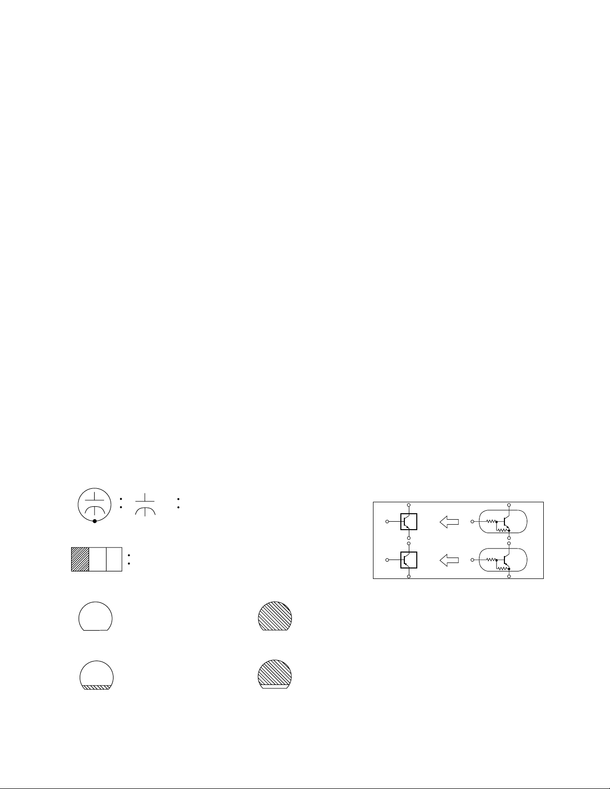
Capacitors and transistors are represented by the following symbols.
CBA Symbols
(Top View) (Bottom View)
+
Electrolytic Capacitor
(Bottom View)
Transistor or Digital Transistor
E C B
(Top View)
NPN Transistor
E C B
(Top View)
(Top View)
PNP Transistor
E C B
(Top View)
Schematic Diagram Symbols
Digital Transistor
E C B
NPN Digital Transistor
PNP Digital Transistor
E C B
1-1 LC2N_SC
Page 3
LIST OF CAUTION, NOTES, AND SYMBOLS USED IN THE SCHEMATIC DIAGRAMS ON
THE FOLLOWING PAGES:
1. CAUTION:
CAUTION: FOR CONTINUED PROTECTION AGAINST RISK OF FIRE, REPLACE ONLY WITH SAME
TYPE_A,_V FUSE.
ATTENTION: UTILISER UN FUSIBLE DE RECHANGE DE MÊME TYPE DE_A,_V.
2. CAUTION:
Fixed Voltage (or Auto voltage selectable) power supply circuit is used in this unit.
If Main Fuse (F601) is blown, first check to see that all components in the power supply circuit are not
defective before you connect the AC plug to the AC power supply. Otherwise it may cause some components
in the power supply circuit to fail.
3. Note:
1. Do not use the part number shown on the drawings for ordering. The correct part number is shown in the
parts list, and may be slightly different or amended since the drawings were prepared.
2. To maintain original function and reliability of repaired units, use only original replacement parts which are
listed with their part numbers in the parts list section of the service manual.
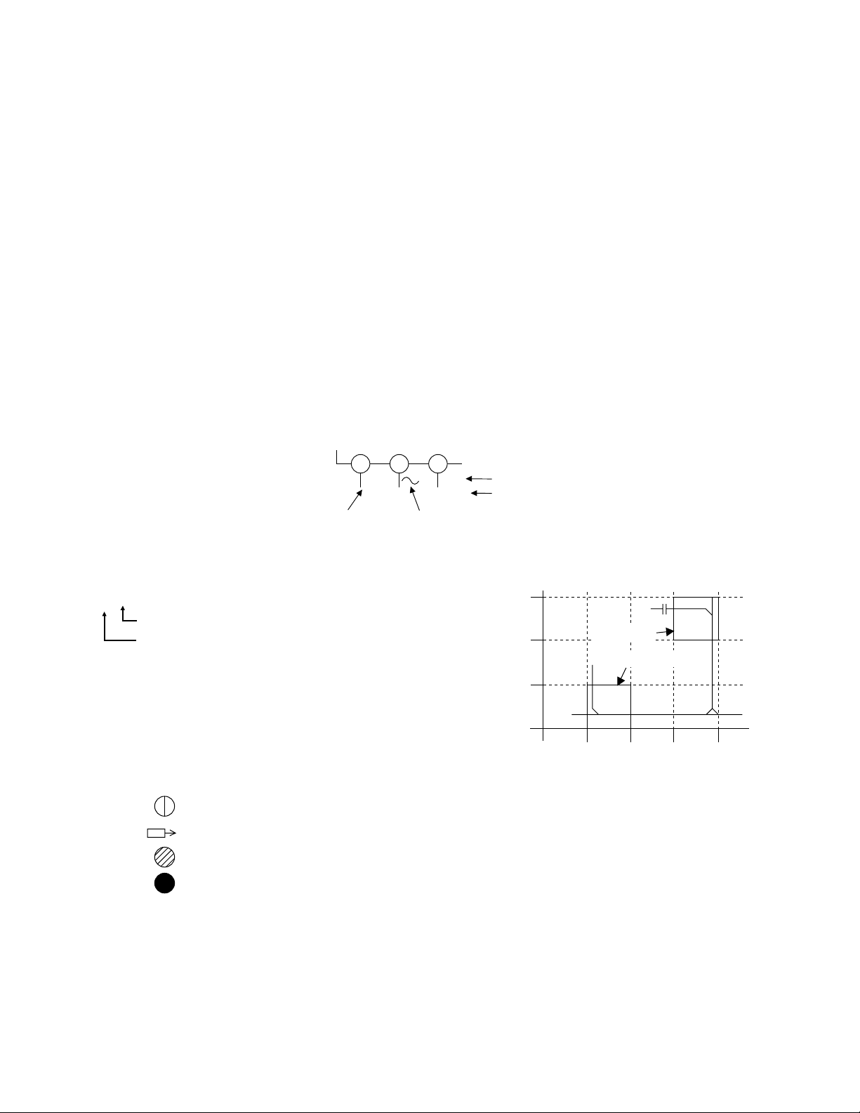
4. Voltage indications on the schematics are as shown below:
Plug the TV power cord into a standard AC outlet.:
2
(Unit: Volt)
1
5.0
(3.0)
3
5.0
(3.0)
Power on mode
Power off mode
5. How to read converged lines
1-D3
Distinction Area
Line Number
(1 to 3 digits)
Examples:
1. "1-D3" means that line number "1" goes to the line number
"1" of the area "D3".
2. "1-B1" means that line number "1" goes to the line number
"1" of the area "B1".
6. Test Point Information
: Indicates a test point with a jumper wire across a hole in the PCB.
: Used to indicate a test point with a component lead on foil side.
: Used to indicate a test point with no test pin.
: Used to indicate a test point with a test pin.
Voltage
Indicates that the voltage
is not consistent here.
3
2
1
AREA D3
1-B1
AREA B1
1-D3
ABCD
1-2 LC2N_SC
Page 4
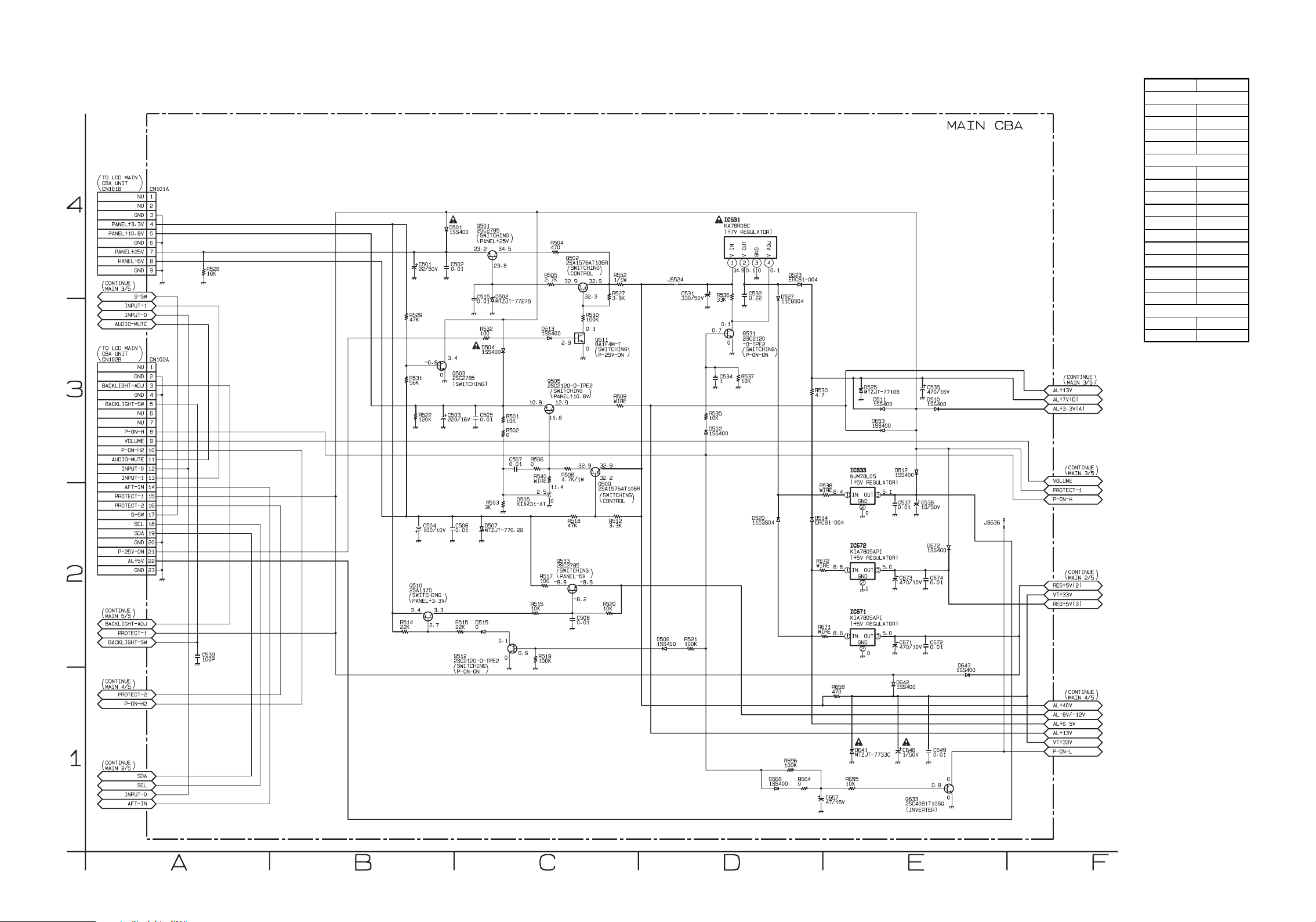
Main 1/5 Schematic Diagram
MAIN 1/5
Ref No. Pos ition
IC531
D-4
IC533
E-3
IC671
E-2
IC672
E-2
Q501 C-4
Q502 C-4
Q503 B-3
Q505 C-3
Q509 C-3
Q510 B-2
Q511 C-3
Q512 C-2
Q513 C-2
Q531 D-3
Q633 E-1
CN101A A-4
CN102A A-3
ICS
TRANSISTORS
CONNECT ORS
1-3
L3118SCM1
Page 5

LCD Main 1/2 Schematic Diagram
LCD MA IN 1/2
Ref No. Pos ition
IC333
B-3
Q301
D-1
CN104
A-3
CN105
A-2
CN311 F-4
CN102B A-4
CONNECT ORS
IC
TRANSISTOR
1-4 L3118SCL1
Page 6

LCD Main 2/2 Schematic Diagram
LCD MA IN 2/2
Ref No. Pos ition
IC151
I-3
IC171
J-3
IC191
H-2
IC192 H-1
IC193
H-2
IC201 J-1
Q131
I-4
Q201
J-1
CN312
L-3
CN101B
L-4
CN103B G-2
ICS
CONNECT ORS
TRANSISTORS
1-5
L3118SCL2
Page 7

Main CBA Top View
Because a hot chassis ground is present in the power
supply circuit, an isolation transformer must be used.
Also, in order to have the ability to increase the input
slowly,when troubleshooting this type power supply
circuit, a variable isolation transformer is required.
CAUTION !
Fixed voltage (or Auto voltage selectable) power supply circuit is used in this unit.
If Main Fuse (F601) is blown , check to see that all components in the power supply
circuit are not defective before you connect the AC plug to the AC power supply.
Otherwise it may cause some components in the power supply circuit to fail.
4A/125V
CAUTION ! :
ATTENTION : Utiliser un fusible de rechange de même type de 4A, 125V.
NOTE:
The voltage for parts in hot circuit is measured using
hot GND as a common terminal.
For continued protection against risk of fire,
replace only with same type 4 A, 125V fuse.
TP403
1-6
TP402
+13V
BL3100F01013-1
Page 8

Main CBA Bottom View
Because a hot chassis ground is present in the power
supply circuit, an isolation transformer must be used.
Also, in order to have the ability to increase the input
slowly,when troubleshooting this type power supply
circuit, a variable isolation transformer is required.
MAIN CBA
Ref No. Position Ref No. Position
IC31
E-4
Q505
C-4
IC531
E-3
Q509
C-3
IC533
E-3
Q510
C-3
IC601 A-5
Q511
C-2
IC671
E-4 Q512 C-2
IC672
E-3 Q513 C-3
IC781
D-2 Q531 C-2
IC801
D-5 Q601 B-5
IC851
D-2
Q603
B-5
IC852 E-2
Q633
A-5
Q661
A-5
Q32 E-4
Q701
D-2
Q401 B-2
Q702
D-2
Q403 B-1 Q703 D-2
Q404 B-1 Q704 E-1
Q405 B-1 Q705 E-1
Q406 B-1 Q706 E-2
Q407 A-1
Q707
E-2
Q408 B-1
Q708
E-2
Q409 A-2
Q802
E-5
Q410 B-1
Q803
D-5
Q411 B-2
Q412 B-2
CN113
E-1
Q415 B-3
CN402
A-2
Q416 B-3
CN403
A-3
Q421 B-1
CN801
E-5
Q422 B-1
CN802
A-5
Q423 B-1 CN101A C-2
Q424 A-2 CN102A D-2
Q427 B-2 CN103A D-2
Q428 B-2
Q501 C-2 TP402 C-2
Q502 C-2 TP403 B-1
Q503 C-2
CONNECTORS
TEST POINT
TRANSISTORSICS
TRANSISTORS
CAUTION !
Fixed voltage (or Auto voltage selectable) power supply circuit is used in this unit.
If Main Fuse (F601) is blown , check to see that all components in the power supply
circuit are not defective before you connect the AC plug to the AC power supply.
Otherwise it may cause some components in the power supply circuit to fail.
4A/125V
CAUTION ! :
ATTENTION : Utiliser un fusible de rechange de même type de 4A, 125V.
NOTE:
The voltage for parts in hot circuit is measured using
hot GND as a common terminal.
For continued protection against risk of fire,
replace only with same type 4 A, 125V fuse.
WF7
PIN 11 OF
CN103A
WF8
PIN 9 OF
CN103A
1-7
WF9
PIN 7 OF
CN103A
WF10
Q704
Emitter
WF11
Q705
Emitter
WF12
Q706
Emitter
WF6
PIN 14
OF IC801
BL3100F01013-1
Page 9

Function CBA Top View
IR Sensor CBA Top & Bottom View
Function CBA Bottom View
BL3100F01013-2
BL3100F01013-3
1-8
BL3100F01013-2
Page 10

Different parts from the previous model
Ref. No. Description Part No.
MECHANICAL PARTS
# RATING LABEL L3118UJ ----------
A6
ELECTRICAL PARTS
LCD MAIN CBA & LIQUID CRYSTAL
PANEL UNIT
1FSA10049
2-1 L3118PL
Page 11

© 2005 Funai Electric Co., Ltd.
All rights reserved. No part of this manual may be reproduced, copied, transmitted, disseminated, transcribed,
downloaded or stored in any storage medium, in any form or for any purpose without the express prior written
consent of Funai. Furthermore, any unauthorized commercial distribution of this manual or any revision hereto
is strictly prohibited.
Information in this document is subject to change without notice. Funai reserves the right to change the content
herein without the obligation to notify any person or organization of such changes.
with the design is a registered trademark of Funai Electric Co., Ltd and may not be used in any way
without the express written consent of Funai. All other trademarks used herein remain the exclusive property of
their respective owners. Nothing contained in this manual should be construed as granting, by implication or
otherwise, any license or right to use any of the trademarks displayed herein. Misuse of any trademarks or any
other content in this manual is strictly prohibited. Funai shall aggressively enforce its intellectual property rights
to the fullest extent of the law.
6615LF
L3118UJ
2005-09-21
 Loading...