


Operating Instructions
Transponder code lock - Part 1
(access control keypad)
Item no. 1582599 / for surface mounting
Item no. 1582600 / for ush mounting Page 2 - 75

TABLE OF CONTENTS
Page
1. INTRODUCTION ................................................................................................................................................. 5
2. EXPLANATION OF SYMBOLS ...........................................................................................................................5
3. INTENDED USE .................................................................................................................................................. 6
4. DELIVERY CONTENT .........................................................................................................................................7
a) ITEM NO. 1582599 ........................................................................................................................................ 7
b) ITEM NO. 1582600 ........................................................................................................................................ 7
5. FEATURES AND FUNCTIONS............................................................................................................................8
6. OPTIONAL DEVICES FOR SYSTEM EXPANSION ............................................................................................ 8
7. SAFETY INSTRUCTIONS ..................................................................................................................................9
8. INSTALLATION ..................................................................................................................................................10
a) ASSEMBLY..................................................................................................................................................10
b) PRECAUTIONS ........................................................................................................................................... 10
9. CONNECTION TERMINALS ............................................................................................................................. 11
10. OTHER FACILITIES ..........................................................................................................................................15
a) ON-BOARD LED INDICATORS ..................................................................................................................15
b) PACIFIER TONES & THE LED SIGNALS ...................................................................................................15
c) JUMPER FOR BACK-LIT SELECTION ....................................................................................................... 15
11. PREPARATION FOR PROGRAMMING ............................................................................................................16
a) CRITERIA FOR CODES AND CARDS ........................................................................................................ 16
b) SECURITY LEVEL OF THE OPERATION MEDIA ......................................................................................16
c) LIST OF USER INFORMATION ..................................................................................................................17
12. PROGRAMMING & OPERATION......................................................................................................................18
a) POWER-UP THE KEYPAD .........................................................................................................................18
b) SET KEYPAD IN PROGRAMMING MODE WITH MASTER CODE ...........................................................18
c) DIRECT ACCESS TO PROGRAMMING MODE WITH “DAP” CODE -- 2 8 2 8 .........................................19
d) SYSTEM REFRESHING WITH “REFRESHING CODE” --- 9 9 9 9 ............................................................19
e) THE DEFAULT VALUES AFTER REFRESHING ........................................................................................20
13. MASTER CODE -- Location 01 .........................................................................................................................21
14. SUPER USER CODE -- Location 02 .................................................................................................................22
15. COMMON USER CODES FOR OUTPUT 1, 2 & 3 -- Locations 03, 04, & 05 ...................................................24
16. USER CODES / CARDS FOR OUTPUT 1, 2 & 3 -- Locations 10, 20 & 30.......................................................25
17. VISITOR CODES (FOR OUTPUT 1 ONLY) -- Location 40 ...............................................................................29
18. DURESS CODES (FOR OUTPUTS 1, 2 & 3) -- Locations 41, 42 & 43 ............................................................30
2

19. OUTPUT MODE & TIMING FOR OUTPUT 1, 2 AND 3 -- Locations 51, 52 & 53 .............................................33
20. SYSTEM REAL-TIME-CLOCK -- Location 55 ...................................................................................................34
21. START & STOP TIMES FOR DAILY INHIBITION OF OUTPUT 1 -- Location 56 .............................................. 35
22. PERSONAL SAFETY AND SYSTEM LOCK-UP -- Location 60 ........................................................................36
23. USER CODE ENTRY MODE – AUTO OR MANUAL -- Location 70 ..................................................................37
24. PACIFIER TONES ON-OFF SELECTION -- Location 71 ..................................................................................38
25. OUTPUT OPERATION ANNOUNCER -- Location 72 .......................................................................................38
26. STATUS LED FLASHING ON-OFF DURING STANDBY -- Location 73............................................................39
27. DOOR FORCED OPEN WARNING & TIMING -- Location 80 ..........................................................................40
28. DOOR PROPPED-UP WARNING & THE DELAY TIME -- Location 81.............................................................40
29. INTELLIGENT EGRESS BUTTON – AN UNIQUE FEATURE OF THE KEYPAD .............................................41
a) INTRODUCTION ......................................................................................................................................... 41
b) WHERE AND WHY “GOING OUT” NEEDS ATTENTION ...........................................................................41
30. EGRESS DELAY, WARNING AND ALARM -- Location 90 ................................................................................43
31. DOOR OPENING ALARM & TIMER -- Location 91 ...........................................................................................45
32. PROGRAMMING LOCATIONS FOR SYSTEM EXPANSION ...........................................................................45
33. WIEGAND DATA OUTPUT MODES -- Location 92 ...........................................................................................46
34. WIEGAND DATA OUTPUT FORMAT -- Location 93 .........................................................................................47
35. OPERATION MODES -- Location 94 .................................................................................................................47
36. CLOSE PROGRAMMING MODE -- (* *) ...........................................................................................................48
37. PROGRAMMING MAKE SIMPLE – FOR GENERAL USERS ..........................................................................48
a) PROGRAMMING ......................................................................................................................................... 48
b) OPERATION ................................................................................................................................................50
38. FACILITIES FOR WIEGAND OUTPUT .............................................................................................................51
39. WIEGAND OUTPUT FORMATS ........................................................................................................................52
40. PROGRAMMING SUMMARY CHART ..............................................................................................................56
41. APPLICATION EXAMPLES ...............................................................................................................................59
a) STAND ALONE DOOR LOCK .....................................................................................................................59
b) INTER-LOCK SYSTEM USING TWO KEYPADS ........................................................................................60
42. APPLICATION EXPANSIONS ...........................................................................................................................62
a) THE AUXILIARY READERS & KEYPAD (OPTIONAL) ...............................................................................62
b) THE SPLIT-DECODERS (OPTIONAL) .......................................................................................................63
c) DUAL-STATION ACCESS CONTROL DOOR LOCK ..................................................................................64
d) MULTI-STATION ACCESS CONTROL DOOR LOCK .................................................................................65
e) SPLIT-DECODED ACCESS CONTROL DOOR LOCK ...............................................................................66
3

f) SPLIT-DECODED MULTI-STATION ACCESS CONTROL DOOR LOCK ...................................................67
43. APPLICATION HINTS FOR THE AUXILIARY TERMINALS ..............................................................................68
a) TAMPER N.C. ..............................................................................................................................................68
b) DOOR SENS ............................................................................................................................................... 69
c) ALARM OUTPUT -- SET THE “K OR A” JUMPER TO “A” ..........................................................................69
d) KEY ACTIVE -- SET THE “K OR A” JUMPER TO “K” .................................................................................70
e) DURESS OUTPUT ......................................................................................................................................70
f) OUTPUT 2 ...................................................................................................................................................71
g) OUTPUT 3 -- DOOR BELL BUTTON (DK-2882B OR D ONLY) ..................................................................71
44. AUXILIARY INFORMATION ..............................................................................................................................72
45. CARE AND CLEANING ..................................................................................................................................... 72
46. DECLARATION OF CONFORMITY (DOC) .......................................................................................................73
47. FCC CAUTION ..................................................................................................................................................73
48. DISPOSAL .........................................................................................................................................................73
49. TECHNICAL DATA .............................................................................................................................................74
a) ITEM NO. 1582599 ...................................................................................................................................... 74
b) ITEM NO. 1582600 ...................................................................................................................................... 75
4

1. INTRODUCTION
Dear customer,
Thank you for purchasing this product.
This product complies with the statutory national and European requirements.
To maintain this status and to ensure safe operation, you as the user must observe these operating instructions!
These operating instructions are part of this product. They contain important notes on commissioning and
handling. Also consider this if you pass on the product to any third party. Therefore, retain these operating
instructions for reference!
If there are any technical questions, please contact:
International: www.conrad.com/contact
United Kingdom: www.conrad-electronic.co.uk/contact
2. EXPLANATION OF SYMBOLS
The symbol with the lightning in the triangle is used if there is a risk to your health, e.g. due to an electric
shock.
The symbol with the exclamation mark in the triangle is used to indicate important information in these
operating instructions. Always read this information carefully.
The arrow symbol indicates special information and advice on operation.
5

3. INTENDED USE
DK-2882 is a self-contained three output relay, vandal resistant and weatherproof keypad. It combines the digital
keypad and proximity EM card reader in one unit.
The keypad has been designed for full feature stand alone access control applications. It is expandable to work with
an optional decoder (DA-2800 or DA-2801) for high security split-decoded operation. It is also compatible with the
auxiliary card reader (AR-2802) and the auxiliary keypad readers (AR-2806, AR-2807 and AR-2809) for upgrading a
stand alone or split-decoded system to multi-station operation.
The keypad is ideally for door strike and alarm arm-disarm controls. It is also a programmable industrial timer (from 1
second to over 24 hours) for automatic operator system.
In the line of DK-2882 keypads are available for surface mount and ush mount versions.
Surface Mount / Gooseneck Mount Keypads:
DK-2882A – Output Relay 1, 2 & 3 Controlled by User Codes / Cards
DK-2882B – Output Relay 1 & 2 Controlled by User Codes / Cards; Output 3 by Bell Button
Flush Mount Keypads:
DK-2882C – Output Relay 1, 2 & 3 Controlled by User Codes / Cards
DK-2882D – Output Relay 1 & 2 Controlled by User Codes / Cards; Output 3 by Bell Button
The keypad is protected against dust and water jet according to IP66 and can be used indoors and outdoors. However
the split decoder is only for indoor use and must be protected from moisture.
For safety and approval purposes, you must not rebuild and/or modify this product. If you use the product for purposes
other than those described above, the product may be damaged. In addition, improper use can result in short circuits,
res, electric shocks or other hazards. Read the instructions carefully and store them in a safe place. Make this
product available to third parties only together with its operating instructions.
All company names and product names are trademarks of their respective owners. All rights reserved.
6

4. DELIVERY CONTENT
a) ITEM NO. 1582599
• Code lock with surface-mounted housing
• Control unit (split decoder DA-2801)
• Mounting materials for code lock (3x screws, 3x dowels, 1x diode)
• Mounting materials for control unit (2x screws, 2x dowels, 1x diode)
• 1x connection cable harness with connector plug
• TX hex key for the code lock
• 2x transponder cards
• Detailed instruction manual (German printed and online, English online only)
• Operating instructions
b) ITEM NO. 1582600
• Combination lock with ush-mounted housing
• Control unit (split decoder DA-2801)
• Mounting materials for code lock (4x screws, 4x dowels, 1x diode)
• Mounting materials for control unit (2x screws, 2x dowels, 1x diode)
• 1x connection cable harness with connector plug
• TX hex key for the code lock
• 2x transponder cards
• Detailed instruction manual (German printed and online, English online only)
• Operating instructions
Up-to-date Operating Instructions
Download the latest operating instructions at www.conrad.com/downloads or scan the QR code
shown. Follow the instructions on the website.
7

5. FEATURES AND FUNCTIONS
• A member of the Tri-Tech series keypads compatible with the optional controllers & reader keypads for system
expansion
• Loaded with the 2nd generation DK-2800 operation software
• Built-in with all the logics for stand alone, split-decoded and multi-station operations
• Controls “Going in” with User Codes / Cards and “Going out” with feature programmable egress button
• Independent control for the three output relays with programming timer
• Total 1,200 User Codes / Cards for controlling of the three outputs
• Indoor or outdoor installation with IP-66 all weather ingress protection
• Stainless steel faceplate combines with die-casting metal back-lit key buttons
• Vandal resistant durable steel housing for surface or gooseneck mounting
6. OPTIONAL DEVICES FOR SYSTEM EXPANSION
The Optional Decoders Available for Split-decoded Operation:
DA-2800 – Full Feature Decoder with RF Remote Control
DA-2801 – Full Feature Decoder
The Auxiliary Reader / Keypad Available for Multi-station Operation:
AR-2802S or A – EM Card Reader
AR-2806S or A – EM Card Reader with Digital Keypad
AR-2807S or A -- EM Card Reader with Digital Keypad
AR-2809S -- EM Card Reader with Digital Keypad
The sufx letter “S” stands for standard version and “A” stands for advanced version. The advanced version
possesses the standand features and also provides Wiegand and RS-232 data outputs for the custom
projects with external controller and PC.
8

7. SAFETY INSTRUCTIONS
Read the operating instructions carefully and especially observe the safety information. If you do
not follow the safety instructions and information on proper handling in this manual, we assume
no liability for any resulting personal injury or damage to property. Such cases will invalidate the
warranty/guarantee.
• The device is not a toy. Keep it out of the reach of children and pets.
• Do not leave packaging material lying around carelessly. This may become dangerous playing material
for children.
• Protect the appliance from extreme temperatures, direct sunlight, strong jolts, high humidity, moisture,
ammable gases, steam and solvents.
• Do not place the product under any mechanical stress.
• If it is no longer possible to operate the product safely, take it out of operation and protect it from any
accidental use. Safe operation can no longer be guaranteed if the product:
- is visibly damaged,
- is no longer working properly,
- has been stored for extended periods in poor ambient conditions or
- has been subjected to any serious transport-related stresses.
• Please handle the product carefully. Jolts, impacts or a fall even from a low height can damage the
product.
• Also observe the safety and operating instructions of any other devices which are connected to the
product.
• Make sure the location for installation has no strong low frequency electro-magnetic wave. Especially in
the range of 100-200 Khz.
• If there is more than one keypads with the same operation frequency installed closely in the location,
make sure that they are at least 60 cm (2 ft) apart from each other to prevention interference.
• Do not apply power to the system while it is in installation.
• Check carefully all the wirings are correct before applying power to the system for testing.
• The code lock has an IP66 protection rating, meaning that it can be installed and used both indoors and
outdoors.
• The control unit (split decoder) must be installed and used in dry indoor areas.
• Make sure that the connection cable is not pinched or damaged by sharp edges.
• Always comply with the accident prevention regulations for electrical equipment when using the product
in commercial facilities.
• Consult an expert when in doubt about the operation, safety or connection of the appliance.
• Maintenance, modications and repairs must only be completed by a technician or an authorised repair
centre.
• If you have questions which remain unanswered by these operating instructions, contact our technical
support service or other technical personnel.
9
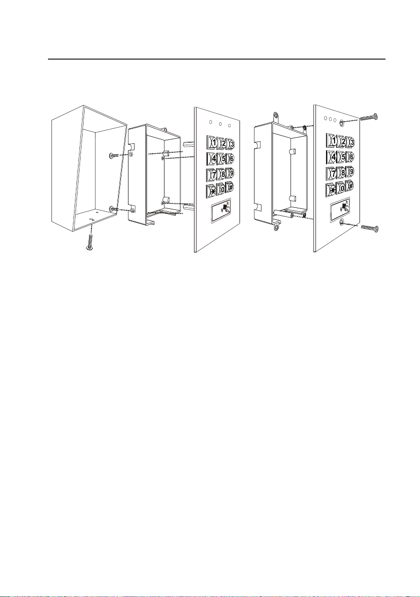
8. INSTALLATION
a) ASSEMBLY
Surface Mount Version Flush Mount Version
Steel Box Plastic inner box Faceplate Plastic back box Faceplate
b) PRECAUTIONS
Prevent Interference:
The EM Card reader is working at the frequency of 125Khz. Installation precautions are necessary.
• Make sure the location for installation has no strong low frequency electro-magnetic wave. Especially in the range
of 100-200Khz
• If there is more than one keypads with the same operation frequency installed closely in the location, make sure
that they are at least 60cm (2ft) apart from each other to prevention interference.
Prevent Accidental Short Circuit:
In the previous experience, most of the damages caused in the installation are accidental touching of the components
on circuit board with the wires carrying power. Please be patient to study the manual to become familiar with the
specications of the system before starting the installations.
• Do not apply power to the system while it is in installation.
• Check carefully all the wirings are correct before applying power to the system for testing.
10
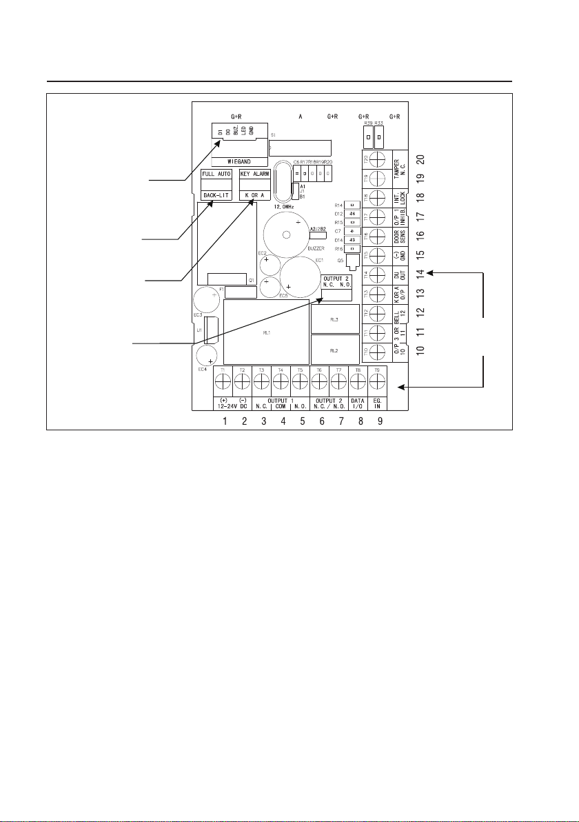
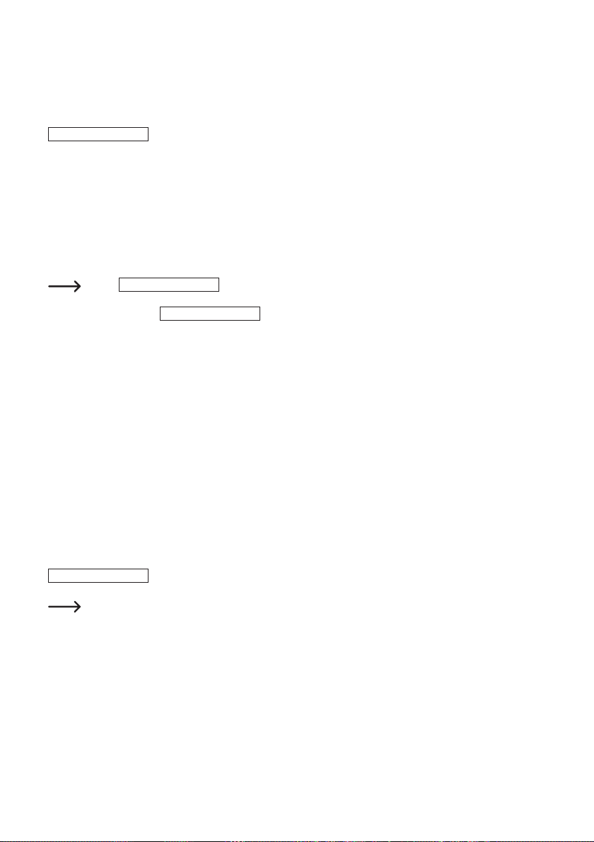
9. CONNECTION TERMINALS
WIEGAND
HARNESS
BACK-LIT JUMPER
K OR A JUMPER
OUTPUT 2
JUMPER
1 - 2: 12-24V DC (Power Input Terminal)
Connect to 12-24V DC power supply. The (-) supply and the (-) GND are the common grounding points of the system.
The system accepts full input voltage range with no adjustment.
3 - 4 - 5: OUTPUT 1 (Output Relay 1)
5 Amp relay dry contact controlled by the Group 1 User Codes/Cards, recommended for door strike. Terminal 3 is
Normally Closed (N.C.), terminal 5 is Normally Open (N.O.) and terminal 4 is the common point of the two contacts.
Use N.C. output for Fail-safe locking device; and N.O. output for Fail-secure locking device. The relay is programmable
for Start/Stop (toggle) mode or Momentary timing mode. See programming Location 51 for the details.
6 – 7: OUTPUT 2 (Output Relay 2)
1 Amp relay dry contact controlled by the Group 2 User Codes/Cards. It is an auxiliary output contact for controlling
security system or automatic operator. It is selectable for N.C. (Normally Closed) or N.O. (Normally Open) with jumper
and the operation mode is programmable for Start/Stop (toggle) or Momentary with timing. See programming Location
52 for the details.
CONNECTION
TERMINALS
11

N.O. N.C.
OUTPUT 2
OUTPUT 2 JUMPER
8: DATA I/O PORT (Data Communication Bus)
The Data I/O port is prepared for setting up a data bus for the connection of the auxiliary reader-keypads and the splitdecoder in system expansion. See the examples in “Application Expansions” section for the details.
9: EG IN (Egress Input)
A Normally Open (N.O.) input terminal referring to (-) ground. With the help of connecting a normally open button to
activate Output 1 for door opening like using Codes/Cards.
Egress button is usually put inside the house near the door. More than one egress buttons can be connected in
parallel to this terminal. Leave this terminal open if not used.
See Programming Locations 90 and 91 for more information about the Egress Button with programmable features.
10 - 11 - 12: OUTPUT 3 (Output Relay 3) --- For DK-2882A & DK-2882C Only*
1 Amp relay dry contact controlled by the Group 3 User Codes or Cards for Output 3 in the version “A” & “C” keypads,
it is an auxiliary output contact for controlling security system or automatic operator. Terminal 10 is Normally Closed
(N.C.), terminal 12 is Normally Open (N.O.) and terminal 11 is the common point of the two contacts. It is programmable
for Start/Stop (toggle) mode or Momentary with timing. See programming Location 53 for the details.
10: OUTPUT 3 (Open Collector Output) --- For DK-2882B & DK-2882D Only*
An NPN transistor open collector output is for version “B” & “D” keypads, which is controlled by the Group 3 User
Codes/Cards. It has the maximum power rating of 24V DC/100mA sink. It is equivalent to an N.O. (Normally Open)
terminal referring to ground. It can be used to drive small power device, such as a relay or a low power control
point of other equipment. This output point is programmable for Start/Stop (toggle) or Momentary with timing. See
programming Location 53 for the details.
11 - 12: DOOR BELL (Relay Contact for Door Bell) --- For DK-2882B & DK-2882D Only*
Door Bell output is for version “B” & “D” only. It is a Normally Open (N.O.) relay dry contact with maximum rating of
24V DC/1Amp. It is a triggering contact of a low voltage door chime. The contact point keeps close as long as the
bell button on the keypad is pressed. See “Application Hints for the Auxiliary Terminals” Section(G) for the details.
13: “K” OR “A” O/P (Keypad Active Output or Alarm Output)
An NPN transistor open collector output with maximum power rating of 24V DC/100mA sink. It is equivalent to an N.O.
(Normally Open) terminal referring to ground. It can be used to drive small power device, such as a relay or a low
power control point for other equipment. This output point is selectable to give Keypad Active Output or Alarm Output
via the “K or A” jumper.
12

K OR A
KEY ALARM
KEY-ALARM JUMPER
• Keypad Active Output (“K”) -- It switches to (-) ground for 10 seconds on each key touch. It can be used to turn
on light, CCTV camera, or buzzer to notify a guard. See Application Hints for more information.
• Alarm Output (“A”) -- It switches to (-) ground while Alarm occurs in order to trigger external alarm to give
notication at remote location.
14: DU OUT (Duress Output)
An NPN transistor open collector output with maximum power rating of 24V DC/100mA sink. It is equivalent to an N.O.
(Normally Open) terminal switching to (-) ground after the Duress Code is entered. Use it to trigger an alarm zone of
a security system, or turn on a buzzer to notify a guard.
15: (-) GND (Common Ground)
A grounding point of the keypad that is common to terminal 2.
16: DOOR SENS N.C. (Door Position Sensing Input -- Normally Close)
A Normally Closed (N.C.) sensing point referring to (-) ground, with the help of a normally closed magnetic contact
monitors the open or close status of the door. It initiates the following functions for the system. Connect it with jumper
to (-) Ground if not used.
• Door Auto Re-lock
The system immediately re-locks the door after it is re-closed before the end of the programmed time for output 1.
It prevents unwanted “tailgate” entry.
• Door Forced Open Warning
The keypad generates “door forced open” warning and alarm instantly once the door is forced to open without a
valid user Code, Card or egress button. The warning lasts as long as the time programmed (1-999 sec). It can be
stopped with an User Code or card for output 1 at anytime. See programming Location 80 for the details.
• Door Propped-up Warning
The keypad generates propped-up warning beeps (does not activates alarm output) while the door is left open
longer than the allowable time programmed. The warning will last as long as the door is open until re-closed. See
programming Location 81 for the details.
• Inter-lock Control
The inter-lock control output always goes to (-) while the door is open, which gives signal to disable the partner
keypad in an inter-lock system. See the Inter-lock terminal 18 description for more information.
• Door Opening Alarm
Door Opening Alarm is designed for the emergency door only. It is always given when the door is opened unless a
valid user code or card is used prior to the door is opened. See programming Location 91 for the details.
13

17: O/P 1 INHIBIT N.O. (Output 1 Inhibit Control Input – Normally Open)
A Normally Open (N.O.) sensing input point for controlling the Output 1, with this terminal connecting to (-) ground, the
Egress Button, the group of User PINs and Cards for Output 1 are all disabled. It is prepared mainly for the cross
wire connection with the “Inter-lock O/P” point of the partner keypad in an Inter-lock system.
The inhibit function does not govern the Duress Codes and the Super User Codes. They are always valid.
18: INTER-LOCK O/P (Inter-lock Control Output)
An NPN transistor open collector output with maximum power rating of 24V DC/100mA sink. It is OFF at normal
condition and it switches to (-) ground immediately for the rst 5 seconds after keying in a valid User Code or reading
a card to operate Output 1, then, it will keep tying to (-) ground during the Door Position Sensor is open circuit due to
door opening. Use this output point to make cross wire connection with the partner keypad’s “O/P 1 Inhibit” point in an
Inter-lock system to prevent both doors can be opened at the same time.
An Inter-lock System:
An inter-lock system is a two-door system that always allows only one of the doors to open during the operation. While
one of the doors is opened, the other door keeps close until the open door is re-closed. It prevents the unauthorized
people dashing into a protected area while the doors are in use.
An inter-lock system needs two keypads and two door position sensing switches for the two doors.
19 - 20: TAMPER N.C. (Tamper Switch Normally Closed Contact)
A normally closed dry contact while the keypad is secured on its box. It is open while keypad is separated from the
box. Connect this N.C. terminal to the 24 hour protection zone of an alarm system if necessary.
The tamper switch in the DK-2882A and DK-2882B is activated by the xing screw of the front plate; in the
DK-2882C and DK-2882D it is activated by a magnet equipped on the back of the plastic box.
14

10. OTHER FACILITIES
a) ON-BOARD LED INDICATORS
RED / GREEN (Right) It lights up in Green for Output 1 activation; and Red for Output 2 activation.
AMBER (Centre) It ashes in Standby. It shows the system status in synchronization with the beep tones.
RED / GREEN (Left) It lights up in Red while one of the outputs is inhibited. It is ashing during inhibition
b) PACIFIER TONES & THE LED SIGNALS
The buzzer and the amber LED indicator give following tones and signals respectively for system status:
In Programming Mode ----- ON
Successful Key Entry 1 Beep 1 Flash
Successful Code / Card Entry 2 Beeps 2 Flashes
Unsuccessful Code / Card Entry 5 Beeps 5 Flashes
Power Up Delay Continuous Beeps Continuous Flashes
Output Relay Activation ** 1 Second Long Beep -----
In Standby *** ----- 1 Flash in 1 Second Interval
System Refreshing ----- Fast Flashes for 2.5 Minutes
Card or Code Already Stored in System 1 Long Beep -----
Keypad link-up with Decoder Failed Continuous 1 Beep/1 sec -----
Real -time-clock stopped after power failure Continuous 3 Fast Beeps/5 secs -----
The standby ashing can be OFF with programming. See Location 73 for the details.
paused.
It is the Wiegand LED for feedback indication. It lights up in Green.
STATUS TONES * AMBER LED
* All Pacier Tones can be ON or OFF through the programming option at Location 71
** The Output Relay Activation beep can be selected through the programming option at Location 72
*** The Standby ashing can be ON or OFF through the programming option at Location 73
c) JUMPER FOR BACK-LIT SELECTION
Full Back-lit The keypad gives dim backlit in standby. It turns to full backlit
Auto Back-lit The backlit is OFF in standby. It turns to full backlit when a key
when a key button is pressed, then back to dim backlit 10
seconds after the last key button is pressed.
button is pressed, then back to OFF 10 seconds after the last key
button is pressed.
FULL AUTO
BACK-LIT JUMPER
15

11. PREPARATION FOR PROGRAMMING
a) CRITERIA FOR CODES AND CARDS
Prime Codes
The prime codes include the a) User Codes, b) Master Code, c) Duress Codes, d) Super User Codes, e) Common
User Codes and f) Visitor Codes. All these codes MUST be unique. It is not allowed to repeat a prime code for second
function.
All the codes in this system can be 4-8 digits for Manual Entry Mode. The codes must be in the same digit length with
the Master Codes for Auto Entry Mode. See Location 70 for the details.
Prime Cards
All the User Cards are prime cards. They are not allowed to program for second function. e.g. a card was programmed
for operating output 1 is not allowed for output 2.
The cards used in this system are 125Khz proximity EM cards.
Secondary User Codes
A Secondary User Code is prepared to enhance the security of an user card, which is a code put after a card. The
keypad requires both card and code are correct to grant an entry. The secondary code can be repeatedly used for a
group of cards; or proprietary with one code for one card.
The keypad will reject repeated use of prime card or prime code in programming and give one long beep
indication.
b) SECURITY LEVEL OF THE OPERATION MEDIA
The keypad provides 5 operation Media for owner’s selection of security level. See programming Location 10, 20 & 30
EM Card Only – Operation Media 1
A general way for access control, just simply read a card to open the door. Security level is moderate but it is user
convenient.
User Code Only – Operation Media 2
A general way for access control, just simply enter a code to open the door. Security level is moderate but it is user
convenient.
EM Card + Common User Code – Operation Media 4
The keypad requires both Card and Common User Code are correct to grant an entry. Common User Code is an
user code for all the cards. Two media are used in door control. The security level is better than just card or user
code alone.
This operation mode can also report Duress Alarm by keying the duress code instead of common user code in
emergency when the user is forced to open the door.
16

EM Card + Group Secondary User Code – Operation Media 3
A secondary user code can be repeatedly used for a group of cards in a department. Owner can make a proprietary
department code for each department in a company. Only the staff of the department holding a card and knowing the
code is accepted to enter. This approach increases the departmental security and prevents a lost card picked up by
other group of people in the company to open the door.
This operation mode can also report Duress Alarm by keying the duress code instead of common user code in
emergency when the user is forced to open the door.
EM Card + Proprietary Secondary User Code – Operation Media 3
The keypad accepts programming with each card having its own proprietary user code to work. It prevents any other
people can use the lost card to open the door. Card with proprietary user code approach is ideal for the area that high
security is the main concern.
This operation mode can also report Duress Alarm by keying in the duress code instead of Secondary user code in
emergency when the user is forced to open the door.
c) LIST OF USER INFORMATION
The keypad can accommodate up to 1,200 users (codes / cards). To avoid confusion and for programming
convenience, it is suggested to make a list recording of the user information. It helps the owner to program the user
codes and cards smoothly and to trace them afterwards in the future. Here is a suggested format of the list.
List of Users (See page 24-28 for reference)
Example:
User Name Location Media User ID Code Card # Remark
1 John 10 1 001 / 001 Output 1
2 May 20 2 001 1234 / Output 2
3 Tom 10 3 002 24680 002 Output 1
4 Tracy 10 4 003 Common 003 Output 1
5
6
7
8
9
10
11
12
13
14
15
16
--
1,000
17
12. PROGRAMMING & OPERATION
a) POWER-UP THE KEYPAD
The keypad gives power-up delay of 1 minute after power has been applied. It is the time frame designed for setting
the keypad to programming mode with DAP code. See the details of “DAP CODE – 2 8 2 8” below.
1. The keypad gives continuous beeps for 1 minute after power-up.
2. The power-up delay can be stopped instantly with 12# if the delay beep is found annoying and setting the
keypad to programming mode with DAP code is not required.
POWER-UP DELAY STOP
1 2 #
3. The keypad will set itself to Normal Operation Mode automatically after the 1 minute power-up delay expired or
it is stopped with 12#.
b) SET KEYPAD IN PROGRAMMING MODE WITH MASTER CODE
It is always necessary to set the keypad in programming mode for feature programming
The keypad is in normal operation after power-up delay. Set it in programming mode with Master Code and validate
it with * * or .
MASTER CODE
0000 **
For those keypads with door bell button, the button is equivalent to the * button.
For the owner’s convenience in programming at the rst time, a Master Code 0 0 0 0 has been put into the
keypad before exit-factory. It is NOT a default code. For security reason, owner should program a personal
Master Code to replace it after the keypad is owned.
The Mains LED (amber) is ON after the keypad conrms it in programming mode with 2 beeps.
DO NOT turn off power while the keypad is in programming mode. Otherwise, it may cause error to the data
in memory.
→
VALIDATION
→
VALIDATION
18
c) DIRECT ACCESS TO PROGRAMMING MODE WITH “DAP” CODE -- 2 8 2 8
In case the Master Code is forgotten, apply the following procedures precisely to set keypad into programming
mode with DAP code:
1. Switch OFF all the power for 1 minute to ensure that the keypad is fully discharged.
2. Switch ON power again. The keypad is in Power-up Mode for 1 minute. The buzzer gives continuous beeps and
the Status LED is ashing. This is the only time frame to accept the DAP code.
3. Press the Egress Button (the button connecting accross EG IN, (Terminal 9) and (-)GND, (Terminal 15) once to
enable the keypad for accepting DAP code. The power-up beep stops after the Egress Button is pressed.
4. Key in the DAP code 2828 and validate it with * * (or ). The Status LED is ON and the keypad is in
programming mode like using Master Code. It is ready to accept new programming data as long as you like until
exit programming mode.
EGRESS BUTTON
PRESS ONCE
5. To program a new Master Code to replace the old one. See “Record A Master Code” stated at “Location 01” for
the details.
The keypad will set itself to normal operation mode 1 minute after power-up if the Egress Button is not
pressed and the DAP code is not keyed in. To set keypad back to power-up mode, repeat procedures 1-4.
DAP CODE
→
2828 * *
→
VALIDATION
d) SYSTEM REFRESHING WITH “REFRESHING CODE” --- 9 9 9 9
The keypad can be refreshed by cleaning all the programmed old data and set it back to default values except the
Master Code.
REFRESHING CODE
9999 #
→
VALIDATION
Make sure that system refreshing is really required before entering the refreshing code.
Refreshing takes few minutes. The status LED (amber) keeps ashing during refreshing.
The keypad is back to its default value after refreshing. Re-program of the desired values are necessary.
19

e) THE DEFAULT VALUES AFTER REFRESHING
LOCATION PARAMETERS DEFAULT FUNCTIONS & VALUES
0 1 Master Code 0 0 0 0 Factory Set, Not a default value *
Super User Codes
0 2
0 3 Common User Code 1 Nil ----- User Program Required
0 4 Common User Code 2 Nil ----- User Program Required
0 5 Common User Code 3 Nil ----- User Program Required
1 0 User Codes & Cards for O/P 1 Nil ----- User Program Required
2 0 User Codes & Cards for O/P 2 Nil ----- User Program Required
3 0 User Codes & Cards for O/P 3 Nil ----- User Program Required
Visitor Codes
4 0
4 1 Duress Code for O/P 1 Nil ----- User Program Required
Duress Code for O/P 2 Nil ----- User Program Required
4 2
4 3 Duress Code for O/P 3 Nil ----- User Program Required
5 1 O/P Mode of The O/P 1 Time = 5 Sec, Momentary
5 2 O/P Mode of The O/P 2 Time = 5 Sec, Momentary
5 3 O/P Mode of The O/P 3 Time = 5 Sec, Momentary
5 5 System Real-Time-Clock Nil ----- User Program Required
5 6 Start & Stop Time Nil ----- User Program Required
6 0 Personal Safety & Lock-out Code = 1, 10 False Code/Card Lock-out 60 Sec
7 0 User Code Entry Mode Code = 2, Manual Entry Mode
7 1 Pacier Tones ON-OFF Selection Code = 1, Pacier Tone ON
7 2 O/P Operation Announcer Code = 1 Sec, Notication Beep ON
7 3 Status LED Standby Flashing ON-OFF Code = 1, Flashing Enabled
8 0 Door Forced Open Warning & Timing Code = 0, Warning Disabled
8 1 Door Propped-up Warning & Delay Code = 0, Warning Disabled
9 0 Egress Delay & Warning
9 1 Door Opening Alarm & Timer Code = 0, Alarm O/P Disabled
9 2 Wiegand Output Mode Code = 1, Disabled
9 3 Wiegand Output Format Code = 1, 26-Bit
9 4 Operation Modes Code = 0, Keypad Mode
Nil ----- User Program Required
Nil ----- User Program Required
Code 1 = 1, Momentary Contact without Warning
Code 2 = 0, Instant, No Delay
The DAP Code 2 8 2 8 and the Refreshing Code 9 9 9 9 are xed in the operating system program. It can
not be changed in any ways.
20

13. MASTER CODE -- Location 01
LOCATION
01
(1) (2) (3)
(1) LOCATION
• Key in Location 01
(2) MASTER CODE
• Master Code is the authorization code for setting the system to programming mode. It is NOT an User Code
operating the output relays.
• The Master Code can be 4 to 8 digits.
• When a new master code is keyed in and conrmed, the old master code is replaced.
• The master code is also the Link-up Code between the keypad and the optional decoder in Split-decoded operation.
(3) VALIDATION
• Press # key once. Two-beep conrms the entry.
Example:
Set a Master Code “2 2 3 3” ---- 01 2233 #
MASTER CODE
→
4 to 8 Digits
→
VALIDATION
#
21

14. SUPER USER CODE -- Location 02
The Super User Code has TWO functions. It is prepared to operate the three outputs and make operation of inhibit
enable / disable to those outputs.
LOCATION
02
(1) (2) (3)
(1) LOCATION
• Key in Location 02
(2) SUPER USER CODE
• The Super User Code can be 4 to 8 digits.
• When a new Super User Code is keyed in and conrmed, the old one is replaced.
(3) VALIDATION
• Pressing # key to conrm code entry.
Example:
• Set a Super User Code “2 5 8 0” ---- 02 2580 #
• Deleted a Super User Code from memory: Key in the Location number and #. ---- 02 #
OPERATION AND FUNCTIONS OF THE SUPER USER CODE
1) Operate Output 1, 2, and 3
• The operation of the Super User Code is just like a normal User Code. Simply key-in the Code with a specic output
number for the desired Output. The Super User Code can also be used to reset an operating output timer instantly.
SUPER USER CODE
# 1
SUPER USER CODE
→
---------- Output 1 Activates or Resets
4 to 8 Digits
→
VALIDATION
#
SUPER USER CODE
SUPER USER CODE
Optional Functions Controlled by Super User Code for Output 1
• Apart from controlling of the three outputs 1, 2, and 3; the Super User Code can also be used to enable the optional
functions controlling Output 1 for user convenience or security enhancement.
• Super User Code and Egress Button are excluded from any system inhibition and lockup functions; they are valid
for door open at anytime for safety.
---------- Output 2 Activates or Resets
# 2
---------- Output 3 Activates or Resets
# 3
22
2) Override The Door Lock Controlled by Output 1 (Keep Door Un-locked)
The Output 1 is usually for door lock control. In some situations, the door may require un-locked for a period of time to
allow door opening without User Code or EM Card for entry / exit convenience. This function Starts / Stops in toggle
with the following code entry.
SUPER USER CODE
• The door is un-locked while the function is enabled.
• Do not forget to stop this function after use because the door is un-locked. Also, the system refuses the optional
functions (3) & (4) while Override function comes into effect.
• This feature is good for all the “Fail-safe electric locks”.
• “Fail-secure electric lock” requires power to keep in un-locked condition. It takes high current all the time while
the function comes into effect and may cause damage to it. This function is not recommended for Fail-secure
electric lock.
While
on the door sensor (such as a magnetic contact) and the User Codes for output 1 are all temporarily
suspended until
The following are the temporarily suspended functions:
• Door Auto-relock
• Door Forced Open Warning (at Location 80)
• Door Propped-up Warning (at Location 81)
• Door Opening Alarm (at Location 91)
• Dual Keypad Inter-lock Operation
• All User Codes Including Super User Code for Output 1
• Duress Output Actuated by The Duress Code for Output 1
# 7
SUPER USER CODE
---------- The Door is Un-locked, Start / Stop in Toggle
# 7 is in operation to hold the door lock open, the functions that rely
SUPER USER CODE
# 7 is keyed in again to release the door hold function.
3) Pause The Scheduled Daily Inhibition for Output 1 (Temporarily Disable The Inhibition)
The scheduled inhibition can be programmed and applied to Output 1 with daily start and stop times. It can be stopped
temporarily if required; such as the staff work overtime after ofce hours going into the inhibition period. This function
Starts / Stops in toggle with the following code entry. It can be done before or during the inhibition period.
SUPER USER CODE
The “INHIBIT” LED (Red) is ON in inhibition and turns to Flashing while pause is into effect.
See Programming Locations 55 & 56 for more information Daily Inhibition.
# 8
---------- Door Lock Operation Resumes, Start / Stop in Toggle
23

4) Inhibit All The User Codes & EM Cards for Output 1 (Disable Access Control Manually)
To enhance the security of the access control keypad, the owner can stop the keypad after ofce hour or while the
house is nobody inside. Once the Output 1 (for door lock control) is inhibited, all the User Codes / Cards for it become
invalid and those people holding the User Code or Card are refused. This function Starts / Stops in toggle with the
following code entry.
SUPER USER CODE
The door is locked during Output 1 inhibited and the “INHIBIT” LED (Red) is ON.
Inhibition applies to all User Codes and EM Cards for Output 1 only. Output 2 and output 3 are not affected.
------ Door Lock Operation Inhibited, Start / Stop in Toggle
# 9
15. COMMON USER CODES FOR OUTPUT 1, 2 & 3 -Locations 03, 04, & 05
The Common User Codes 1, 2 and 3 are prepared for operating of the Output 1, 2 and 3 respectively as an enhance
code. The Common User Codes MUST work in the form of “Card + Common Code” to operate the outputs to increase
the security of the access control system. See Media 4 at Locations 10, 20 & 30 for more information.
Common User Code alone can NOT operate the Outputs directly.
LOCATIONS
03 - 05
(1) (2) (3)
(1) LOCATIONS
03 -- Location Stores The Common User Code for Output 1
04 -- Location Stores The Common User Code for Output 2
05 -- Location Stores The Common User Code for Output 3
(2) COMMON USER CODES
• The Common User Code can be 4 to 8 digits.
• When a new Common User Code is keyed in and conrmed, the old one is replaced.
(3) VALIDATION
• Pressing # key to conrm code entry.
Example:
• Set a Common User Code “1 3 5 7” for Output 1 ---- 03 1357 #
• Deleted a Common User Code from memory: Key in the Location number and #. ---- 03 #
COMMON USER CODE
→
4 to 8 Digits
→
VALIDATION
#
24

16. USER CODES / CARDS FOR OUTPUT 1, 2 & 3 -Locations 10, 20 & 30
Total 1,200 User Codes / Cards are available for controlling of the three outputs.
LOCATIONS
10 - 30 1 - 5 000 - 999
(1) (2) (3) (4) (5)
(1) LOCATIONS (User Groups)
10 – Group 1 – 1,000 User Codes / Cards for controlling Output 1
20 – Group 2 – 100 User Codes / Cards for controlling Output 2
30 – Group 3 – 100 User Codes / Cards for controlling Output 3
(2) MEDIA (Operation Media) - please also see page 16-17 for more information of their security level
1 – Cards Only – 125Khz Proximity EM Card
2 – User Codes Only – 4-8 Digits
3 – Cards + Secondary User Code(s) – See Note (a)
4 – Cards + Common User Code – See Note (b)
5 – Delete Cards / User Codes from the selected User ID – See Note (c)
0999 – Group Clearing. Clear all the User Codes & Cards of the selected User Group Location. Clearing takes
(3) USER ID (The IDs of The User Codes and Cards)
000 – 999 – 1,000 User IDs for the User Codes & Cards in User Group 1 (Output 1)
001 – 100 – 100 User IDs for the User Codes & Cards in User Group 2 (Output 2)
001 – 100 – 100 User IDs for the User Codes & Cards in User Group 3 (Output 3)
(4) CARD / USER CODE
Read EM Card or key in User Code into each assigned User ID.
(5) VALIDATION
Press the # key once. Two-beep conrms the entry.
The Secondary User Code is a user code putting after a card in programming. It can be a proprietary user
code for each user card or a code repeatedly used for a group of user cards as group user code (e.g. for a
group of staff working in the same department).
The Common User Codes for the Output 1, 2 & 3 have been programmed rst at Locations 03 04 & 05
respectively. It is not necessary to key in the code again in programming here and it will follow the card
automatically after the card is read.
Deletion of an User Code or Card (if the card was lost) can be done by keying-in its ID number For deleting
an existing cards, simply read the card once and conrm. It does not require the ID number. The Card
includes the combinations of (1) Card Only, (2) Card + Secondary User Code and (3) Card + Common User
Code.
MEDIA
→
few seconds to a minute.
→
USER ID
CARD / USER CODE
→
Card / User Code Entry
→
VALIDATION
#
25

EXAMPLES – PROGRAMMING AND OPERATION
Example 1 -- EM Card Only:
Programming:
(a)
Read Card
#
10 1 001
(a) (b) (c) (d) (e)
(a) The card is programmed for operating Output 1
(b) The operation is medium EM Card only
(c) Take ID number 001 in Group 1 to store the card, which is one of the IDs in 000-999
(d) Put the card close to the reader, one beep conrms the reading
(e) Press # to store the “Card”, two-beep conrms a valid entry
Operation: (while the system is back to operation mode)
Read Card
(a) Read the EM card. Two-beep conrms the card is read and Output 1 activates
Example 2 -- Private User Code Only:
Programming:
20 2 001 1234 #
(a) (b) (c) (d) (e)
(a) The Private User Code is programmed for operating Output 2
(b) The operation medium is Private User Code only
(c) Take ID number 001 in Group 2 to store the Private User Code, which is one of the IDs in 001-100
(d) Put Private User Code “1 2 3 4” into the storage location
(e) Press # to store the “Private User Code”, two-beep conrms a valid entry
Operation: (while the system is back to operation mode)
1234 #
(a) (b)
(a) Key in the Private User Code “1 2 3 4”
(b) Conrm it with the # key. Output 2 activates
Example 3 -- EM Card + Secondary User Code:
Programming:
10 3 002
(a) (b) (c) (d) (e) (f)
26
Read Card
24680 #

(a) The card is programmed for operating Output 1
(b) The operation medium is EM Card + Secondary User Code
(c) Take the ID number 002 in Group 1 to store the Card & Code, which is one of the IDs in 000-999
(d) Put the card close to the reader. One beep conrms the reading
(e) Put Secondary User Code “2 4 6 8 0” after reading of card
(f) Press # to store the “Card + Secondary User Code”, two-beep conrms a valid entry
Operation: (while the system is back to operation mode)
Read Card
(a) (b) (c)
(a) Read the EM card. Two-beep conrms the reading and 30 seconds waiting time is given for entry of the User Code,
the Amber LED keeps ashing
(b) Key in the Secondary User Code “2 4 6 8 0”
(c) Conrm it with the # key. Output 1 activates
24680 #
Example 4 -- EM Card + Common User Code:
Programming:
10 4 003
(a) (b) (c) (d) (e)
(a) The card is programmed for operating Output 1
(b) The operation medium is “EM Card + Common User Code”
(c) Take ID number 003 in Group 1 to store the card, which is one of the IDs in 000-999
(d) Read the EM card. One beep conrms the reading. (No need to key in a Common User Code but there MUST be
a Common User Code already recorded in Location 03; (or 04, 05 for O/P 2, O/P 3).
(e) Press # to store the “Card”. Two-beep conrms a valid entry
Operation: (while the system is back to operation mode)
Read Card Common User Code
(a) (b) (c)
Read Card
#
#
(a) Read the EM card. Two-beep conrms the reading and 30 seconds waiting time is given for entry of the Common
User Code, the Amber LED keeps ashing
(b) Key in the Common User Code “1 3 5 7” (the number programmed in “Location 0 3” for Output 1 in the previous
Example)
(c) Conrm it with the # key. Output 1 activates
Example 5 -- Delete An User Code & / or EM Card (for O/P 1, 2 or 3):
Delete An User Code or A Lost EM Card
10 5
(a) (b) (c) (d)
User ID
#
27

(a) Key in the User Group that the User ID belongs to. “10” for Group 1, “20” for Group 2, and “30” for Group 3
(b) Key in “5” that is the Command Code for making a deletion
(c) Key in the User ID that stored the User Code, the lost EM card or the EM Card+User Code
(d) Press the # key. Two-beep conrms a valid entry and the Code and/or Card in that User ID is cleared
Delete an EM Card
10 5
(a) (b) (c) (d)
(a) Key in the User Group that the EM Card belongs to. “1 0” for Group 1, “2 0” for Group 2,.and “3 0” for Group 3
(b) Key in “5” that is the Command Code for making a deletion
(c) Read the EM card. One-beep conrms the reading. Read the Card only also makes a valid deletion to the Card
working with the Common User Code or the Secondary User Code
(d) Press the # key. Two-beep conrms a valid entry. The EM Card in that User ID is cleared. Key in the User ID is not
required.
Read Card
#
Example 6 – Clear The Whole Group of Users:
Whole group of users including the Codes and Cards can be cleared with the following command.
10 0999 #
(a) (b) (c)
(a) The User Group 1 – “10” is selected to be cleared. “20” for Group 2 & “30” for Group 3
(b) Key in the Group Deletion Command, 0 9 9 9
(c) Conrm the deletion with #. All the User Codes and Cards in Group 1 are cleared. It takes few seconds to a minute
to complete depending on the data stored.
Example 7 – Report A Duress While Using EM Card:
The Duress Codes are Prime User Codes in the system. In the “EM Card + Secondary User Code” or “EM Card +
Common User Code” operation, they can be used to replace the “Secondary User Code” or the “Common User Code”
to operate the specic output and report a duress alarm event. Programming is not required. The system has this
function automatically while Duress Code exists.
Operation: (while the system is in the operation mode)
Read Card Duress Code
(a) (b) (c)
(a) Read the EM card. Two-beep conrms the reading and 30 seconds waiting time is given for entry of the Duress
Code, the Amber LED keeps ashing
(b) Key in one of the Duress Codes for the specic output (the Code programmed in “Location 41, 42, or 43” for Output
1, 2 and 3 respectively)
(c) Conrm it with the # key. The specic Output activates in a normal way and the Duress Output also activates to
report Duress Event to an alarm system.
The Duress Event can not be reported if the operation mode is EM Card alone. It is required to key in the
Duress Code directly instead of EM card to report Duress Event.
#
28

17. VISITOR CODES (FOR OUTPUT 1 ONLY) -Location 40
The Visitor Codes are temporary user codes for Output 1 (mainly for door strike in access control). They can be
programmed as “One Time Codes” or “Codes with Time Limit”. The Visitor Codes will be cleared automatically after
use if they are one time codes, or, when the allowed time expires.
LOCATION
40 01 - 50 00 or 01 - 99
(1) (2) (3) (4) (5)
(1) LOCATION
Key in Location 40
(2) VISITOR ID
01 - 50 --- 50 Visitor IDs for the 50 visitor codes. They are Two-digit numbers
0999 --- Clear all the Visitor Codes in Location 40. Please see the Programming example below for the details.
(3) VALID PERIOD
The codes in this box MUST be two digits and they represent the time of operation.
00 --- One Time Code
One Time Code has no time limit but it can only be used for ONCE. It is cleared by the system automatically after use.
01 - 99 --- Time Limit in Hour(s)
The Visitor Code can be set with the valid time limit of 1 Hour to 99 Hours with a two-digit number of 01 to 99. The
visitor code is cleared by the system when the time limit reaches.
(4) VISITOR CODES
• The Visitor Codes can be 4-8 digits for Manual Mode code entry.
• The Visitor Codes MUST be in the same digit length with the Master Code for Auto Mode code entry.
• The Visitor Codes can not reset Duress Output.
• When a new Visitor Code is put in the same Code box, the old code is replaced.
All Visitor Codes will be cleared after power down to prevent extension/confusion of their valid time
limit.
(5) VALIDATION
Press # key once. Two-beep conrms the entry.
→
VISITOR ID
→
VALID PERIOD
VISITOR CODE
→
4-8 DIGITS
VALIDATION
→
#
EXAMPLES:
Example 1: Set a “One Time Visitor Code” with the number of “1 2 6 8” for the Output 1
40 01 00 1268 #
(a) (b) (c) (d) (e)
29

(a) Visitor Code Programming, (b) The Visitor ID, (c) An One Time Code, (d) The Visitor Code, (e) Entry Conrmation
Example 2: Set a “Visitor Code” with the number of “1 3 7 8” that is valid for three hours
40 02 03 1378 #
(a) (b) (c) (d) (e)
(a) Visitor Code Programming, (b) The Visitor ID, (c) Valid for 3 Hours, (d) The Visitor Code, (e) Entry Conrmation
Example 3: Delete a “Visitor Code” from Vistor ID 02 in the memory
40 02 #
(a) (b) (c)
(a) Visitor Code Programming, (b) The Visitor ID, (c) Delete Conrmation
Example 4: Clear all “Visitor Codes” in Location 40
40 0999 #
(a) (b) (c)
(a) Visitor Code Location, (b) The Deletion Command Code, (c) Conrmation, all Visitor Codes are cleared
18. DURESS CODES (FOR OUTPUTS 1, 2 & 3) -Locations 41, 42 & 43
Duress Codes are prepared for those Important Persons in case of DURESS while he is operating the access control
keypad. The duress code operates like a normal User Code for Output 1, 2 or 3, and at the same time activates the
Duress Output without any indication. The user may use it to report an emergency and ask for help silently when he is
forced to operate the keypad if the Duress Output is connected with a security system (for example, an Auto-dialer).
The Duress Codes are always valid. They are not governed by any inhibit or lockup function in the system.
LOCATIONS
41 - 43 01 - 50
(1) (2) (3) (4)
CODE ID
→
DURESS CODE
→
4-8 DIGITS
→
VALIDATION
#
(1) LOCATIONS
41 – Duress Codes for Output 1
42 – Duress Codes for Output 2
43 – Duress Codes for Output 3
30

(2) DURESS CODE IDs
01 - 50 50 Duress Code IDs for The Output 1
01 - 10 10 Duress Code IDs for The Output 2
01 - 10 10 Duress Code IDs for The Output 3
0999 = Clear all the Duress Codes from the selected Location group.
Please see the programming example below for the details.
(3) THE DURESS CODES
50, 10 and 10 Duress Codes can be programmed for Output 1, 2 and 3 respectively. They are stored in their two-digit
Code ID box. When a new Code is put into the same Code ID box, the old code is replaced.
• The Duress Codes are 4-8 digits for Manual Mode code entry.
• The Duress Codes MUST be in the same digit length with the Master Code for Auto Mode code entry.
• Always set a Duress Code that is easy to remember in Panic Situation. Only one number different from the daily
used User Code is highly recommended.
• Example: User Code is 1 3 6 9, then 3 3 6 9 or 1 3 6 0 might be a good choice for the Duress Code.
• The Duress Code can also be used to replace the Secondary User Code or Common User Code in Card
reading for the Duress reporting.
(4) VALIDATION
Press # key once. Two-beep conrms the entry.
EXAMPLES:
Example 1: Set a “Duress Code” with the number of “3 3 6 9” for Output 1
41 01 3369 #
(a) (b) (c) (d)
(a) Duress Code for Output 1, (b) Duress Code ID, (c) The Duress Code, (e) Entry Conrmation
Example 2: Set a “Duress Code” with the number of “2 3 9 8 0” for Output 2
42 01 23980 #
(a) (b) (c) (d)
(a) Duress Code for Output 2, (b) Duress Code ID, (c) The Duress Code, (e) Entry Conrmation
Example 3: Delete an Output 1 “Duress Code” from Duress Code ID 01 in the memory
41 01 #
(a) (b) (c)
(a) Duress Code for Output 1, (b) The Duress Code ID, (c) Delete Conrmation
31

Example 4: Clear The Whole Group of Duress Codes from Location 41:
41 0999 #
(a) (b) (c)
(a) Group Location 41, (b) The Group Deletion Command, (c) Conrmation, all Duress Codes in Location 41
are cleared.
OPERATION AND FUNCTION OF THE DURESS CODE
The Duress Code(s) has double actions when it is keyed in. It activates the Duress Output (for duress alarm) and at
the same time activates the specic Relay Output 1, 2 or 3 just like a normal User Code. The Duress Code always
activates the Relay Output in its group, but, does not de-activate (stop) the Duress Output. ONLY a normal User
Code or Card in anyone of the user groups, or a Super User Code can reset (de-activate) the Duress Output.
For Example:
Key in The Duress Code 3 3 6 9 of the Group 1 (for Output 1) To Command The Duress Function:
3369# ----- Duress Output activates (switches to (-) ground) & Output 1 activates.
Key in The Duress Code 3 3 6 9 in Group 1 (for Output 1) Again:
3369# ----- Duress Output keeps activating and no change in its state (keeps to (-) ground) & Output 1 activates
Key in A Normal User Code to Reset Duress (For Example: 1369 is An User Code for Output 1):
1369# ----- Duress Output resets (back to OFF state) but does not activate Output 1.
Report Duress in EM Card Operation
The Duress Codes are Prime User Codes in the system. In the “EM Card + Secondary User Code” or “EM Card
+ Common User Code” operation, they can be used to replace the “Secondary User Code” or the “Common User
Code” to operate the specic output and report a duress alarm event. Programming is not required. The system has
the function automatically while Duress Code exists.
again.
Operation: Taking Duress Code 3 3 6 9 in Group 1 for Output 1 As Example
Read Card
(a) (b) (c)
a) Read the EM card. Two-beep conrms the reading and 30 seconds waiting time is given for the entry of Duress
Code, the Amber LED keeps ashing
b) Key in the Duress Codes 3 3 6 9 for operating Output 1
c) Conrm it with the # key. Output 1 activates in a normal way and the Duress Output also activates to report
Duress Event to an alarm system if connected.
Duress Event can not be reported with EM Card alone. User can only directly use Duress Code to open the
door and report duress event in emergency
3369 #
32

19. OUTPUT MODE & TIMING FOR OUTPUT 1, 2 AND 3
-- Locations 51, 52 & 53
The three relay outputs are programmable for Start/Stop or Timing modes. Apart from door access control, alarm
arm-disarm control, they are also universal timers for automatic operators in industry with their 99,999 seconds
(over 24 hours) programmable timer.
LOCATIONS
51 - 53 0 or 1 - 99999 #
(1) (2) (3)
(1) LOCATIONS
51 -- Location for Output 1
52 -- Location for Output 2
53 -- Location for Output 3
(2) OUTPUT MODE & TIMING
0 - Start /Stop Mode (Toggle)
The number 0 sets the output to Start / Stop mode. The output Starts when an User Code and/or Card is entered/
read; the output Stops when an User Code and/or Card is entered/read again.
1 - 99999 -- Seconds Momentary --- (Default -- Momentary 5 Seconds)
The output can be set in Momentary Mode with the time of 1 second to 99,999 seconds. The output will reset
automatically when the time expires.
(3) VALIDATION
Press # key once. Two-beep conrms the entry.
OUTPUT MODE & TIME
→
VALIDATION
→
RESET OUTPUT TIMER WITH SUPER USER CODE
The Output Timer can be RESET manually at anytime with the Super User Code that operates the desired output
before the end of the time.
Example:
Reset Output 1 Timer --
Reset Output 2 Timer --
Reset Output 3 Timer --
SUPER USER CODE
SUPER USER CODE
SUPER USER CODE
#1 ------------- Output 1 stops
#2 ------------- Output 2 stops
#3 ------------- Output 3 stops
33

20. SYSTEM REAL-TIME-CLOCK -- Location 55
This 24 hour real-time-clock provides the daily time base for starting and stopping the function of inhibition to relay
output 1 (mainly for electric door lock strike).
No real-time-clock setting is required if daily start-stop inhibition at Location 56 is not enabled.
LOCATION
55 hh : mm #
(1)
(1) LOCATION
Key in Location 55
(2) CURRENT REAL TIME
HH : MM – The current time in Hour and Minute. The allowed time gure is 00:00 – 23:59
The time setting is based on 24 hours daily with the rst two digits for hours and the last two digits for minutes.
The time in second always starts at 0 0.
(3) VALIDATION
Press # key once.
Two-beep conrms the setting and the clock starts to count in 24 hour basis from the programmed current time.
Programming Examples:
a) Set the current time of “10:30” (AM) to the keypad ---- 55 1030 #
b) Set the current time of “6:45” (PM) to the keypad ------ 55 1845 #
CURRENT REAL TIME
→
HOURS MINUTES
VALIDATION
→
(3)
(2)
The real-time-clock stops after power failure, which makes the real-time inhibition loses its time base. It is
necessary to re-program the system’s real-time-clock unless the keypad is back up with UPS.
The keypad gives warning beeps of 3 fast beeps / 5 seconds continuously after power failure until the
No “after power failure warning beep” will be given if Location 56 is not programmed with Start/Stop
Suggest to program the clock every 3-6 months to keep time accuracy; or when time deviation is found.
real-time-clock is re-programmed.
times.
34

21. START & STOP TIMES FOR DAILY INHIBITION OF
OUTPUT 1 -- Location 56
Setting with start and stop times into the keypad, the real-time inhibition period for output 1 will recycle daily until the
time settings are cleared.
This function works with the real-time-clock. Set up the real-time at Location 55 is necessary.
For safety reason, the Egress Button is designed always valid. The door lock (controlled by output 1) can be opened
with it at anytime during inhibition.
LOCATION
56 hh : mm hh : mm #
(1)
(1) LOCATION
Key in Location 56
(2) START TIME
HH : MM – Set the real-time inhibition starting time in Hour and Minute. The allowed time gure is 00:00 – 23:59
The starting time is based on 24 hours daily with the rst two digits for hours and the last two digits for minutes.
The time in second always starts at 0 0.
(3) STOP TIME
HH : MM – Set the real-time inhibition stopping time in Hour and Minute. The allowed time gure is 00:00 – 23:59
The stopping time is based on 24 hours daily with the rst two digits for hours and the last two digits for minutes.
The time in second always starts at 0 0.
(4) VALIDATION
Press # key once.
Two-beep conrms the setting.
→
START TIME
HOURS MINUTES
(2)
→
STOP TIME
HOURS MINUTES
(3)
VALIDATION
→
(4)
Programming and Operation Examples:
Set the starting and stopping time for the real-time inhibition period
a) Set Inhibition Period from 12:30 PM (today) – 1:30 PM (same day) for lunch time:
56 1230 1330 #
b) Set Inhibition Period from 6:30 PM (today) – 8:15 AM (next day) for ofce close:
56 1830 0815 #
35

• The start and stop time gures are 24 hours basis. They are 4-digit gures from the smallest 00:00 to the largest
23:59.
• Entry of the two gure values from Small (Start) to Large (Stop) for the period of inhibition; the inhibition will start
and stop in the same day. See example (a).
• Entry of the two gure values from Large (Start) to Small (Stop) for the period of inhibition; the inhibition will start
at the time of the day; thus stop in the next day. See example (b).
• The keypad does not accept the “Start” and “Stop” times with same value. The two time gures must be different.
Clear the function of inhibition
Clear the time settings to stop the function of inhibition:
56 #
Pause the real-time inhibition manually
The real-time inhibition can be stopped temporarily if require; such as the staff work overtime in ofce. The inhibition
can be paused manually with Super User Code before or during the inhibition period. The pause is toggle and does
not affect the real time period counting.
Super User Code
Super User Code
The “INHIBIT” LED(Red) is ashing during the paused period; and it is ON after inhibition resumes.
Open door lock with Super User Code at anytime
The Super User code is valid all the time even in the inhibition period. This function does not affect the real time period
counting.
Super User Code
# 8 ---- Inhibition paused [Inhibit LED(Red) Flashing]
# 8 ---- Inhibition resumes [Inhibit LED(Red) ON]
# 1 ---- The door is open
22. PERSONAL SAFETY AND SYSTEM LOCK-UP --
Location 60
LOCATION
60
(1) (2) (3)
(1) LOCATION
Key in Location 60
36
LOCK-UP OPTIONS
→
1 to 2 Digits
→
VALIDATION
#

(2) LOCK-UP OPTIONS
The Options are represented by the following Numbers. They are described below:
1 --- After 10 successive false Card/User Code trials, the keypad locks during 60 seconds.
-- (Default)
2 --- After 10 successive false Card/User Code trials, activates the Duress output to switch to (-) ground. The Duress
Output can be released with any user Code or Card in the User Group 1 or Super User Code.
5 - 10 --- Selection of after 5 to 10 successive Card/User Code trials, the keypad locks during 15 minutes. The
keypad can be reset to release the lock-up with the “Super User Code” in the following way.
Example: Release the lock-up --
SUPER USER CODE
#9
00 --- Disappearance of all the above lock-up securities.
(3) VALIDATION
Press # key once. Two-beep conrms the entry
23. USER CODE ENTRY MODE – AUTO OR MANUAL
-- Location 70
LOCATION
70 1 or 2 #
(1) (2) (3)
(1) LOCATION
Key in Location 70
(2) USER CODE ENTRY MODES
Two modes 1 and 2 are available for User Code entry options. The EM Card is always in Auto Entry Mode and is
not affected by the selection here.
ENTRY MODES
→
VALIDATION
→
1 --- Auto Entry Mode
Auto Entry Mode requires no pressing of the # key after code entry for code checking.
In the Auto Entry Mode, the User Codes MUST be set in the same digit length of the Master Code (For example,
if the Master Code is 5 digits, then all User Codes must be in 5 digits as well. All other User Codes not in 5 digits
become invalid). When the number of digits reaches, the system will check the User Code automatically. Good for
high trafc access control.
2 --- Manual Entry Mode – (Default)
Manual Entry Mode always requires the # key following the User Code for code checking. The User Codes can be
4-8 digits arbitrary and they are NOT required to be in the same digit length of the Master Code. Manual Entry
increases the level of security in code trial by the unauthorized people.
(3) VALIDATION
Press # key once. Two-beep conrms the entry
37

24. PACIFIER TONES ON-OFF SELECTION -- Location 71
LOCATION
71 1 or 0 #
(1) (2) (3)
(1) LOCATION
Key in Location 71
(2) FUNCTION MODES FOR PACIFIER TONES
Pacier Tone is the Beep Tones from the keypad, which include the tones of Successful Key entry (1 beep) and the
Unsuccessful User Code/Card entry (5 beeps).
The beeps for the Warning and the Power-up Delay do not belong to pacier tones and can not be OFF.
FUNCTION MODES
→
VALIDATION
→
1 --- Pacier Tone ON – (Default)
All the Pacier Tones available from the keypad are enabled. They are the response tones indicating the
operation status of the keypad after a Card/User Code is entered.
0 --- Pacier Tone OFF
All the Pacier Tones are OFF. Good for place needs for a silent environment.
(3) VALIDATION
Press # key once. Two-beep conrms the entry
25. OUTPUT OPERATION ANNOUNCER -- Location 72
LOCATION
72 0, 1 or 2 #
(1) (2) (3)
FUNCTION MODES
→
VALIDATION
→
(1) LOCATION
Key in Location 72
(2) FUNCTION MODES FOR OUTPUT ANNOUNCER
Output announcer gives notication beep on the operation status of the outputs. There are two notication modes
available for the selection.The notication is also OFF while the Pacier Tone OFF mode in the Location 71 is selected.
In multi-station operation, the output announcer only goes to the keypad that has been operated but not all
the keypads in the system.
0 --- No Notication
The output operation notication is OFF but does note affect the normal pacier tones.
38

1 --- 1 Second Long Notication -- (Default)
1 second notication beep is given when the output relay activates. It is prepared to notify the person outside the door
when the lock is released and the door can be opened. It is good for door lock that gives no sound when it activates,
such as a magnetic lock.
2 --- 2 Short Beeps Notication
2 short beeps notication is given when the output relay activates.
(3) VALIDATION
Press # key once. Two-beep conrms the entry
26. STATUS LED FLASHING ON-OFF DURING STANDBY
-- Location 73
LOCATION
73 1 or 0 #
(1) (2) (3)
(1) LOCATION
Key in Location 73
(2) FUNCTION MODES FOR STANDBY FLASHING LIGHT
Some people nd the ashing light of the status LED (the amber LED) is annoying during standby, especially at the
night time. The standby ashing can be ON-OFF with the setting here.
FUNCTION MODES
→
VALIDATION
→
1 --- Standby Flashing ON -- (Default)
The Status LED gives Standby Flashing all the time. It also gives the light indications showing the operation status
of the system.
0 --- Standby Flashing OFF
The Standby Flashing is OFF but it does not affect the system status indications.
(3) VALIDATION
Press # key once. Two-beep conrms the entry
39

27. DOOR FORCED OPEN WARNING & TIMING --
Location 80
LOCATION
80 0 or 1 - 999 #
(1) (2) (3)
(1) LOCATION
Key in Location 80
(2) FUNCTION MODES FOR DOOR FORCED OPEN WARNING
The Door Forced Open Warning function works with a Door Position Sensing switch equipped on the door (usually a
magnetic contact). Once a Timing Figure is put into the Function Mode box, the warning mode is enabled.
0 --- Door Forced Open Warning OFF – (Default)
1 - 999 --- Door Forced Open Warning & Alarm Enabled & Timing
The Timing Figure for the Warning can be 1-999 seconds. The keypad generates the door forced open warning beeps
and activates the alarm output (Terminal 13) instantly if the door is forced to open without a valid User Code/Card or
pressing of Egress Button. The beeps and alarm will last as long as the time set on the timer and it can be stopped at
anytime with an User Code/Card in Group 1 before the end of the time.
The Manner of The Door Forced Open Warning:
• The door is forced to open (without using Code/Card or Egress Button) – Warning & Alarm
• The door is opened with Code/Card – No Warning or Alarm
• The door is opened with Egress Button – No Warning or Alarm
(3) VALIDATION
Press # key once. Two-beep conrms the entry
FUNCTION MODES
→
VALIDATION
→
28. DOOR PROPPED-UP WARNING & THE DELAY TIME
-- Location 81
LOCATION
81 0 or 1 - 999 #
(1) (2) (3)
(1) LOCATION
Key in Location 81
40
FUNCTION MODES
→
VALIDATION
→

(2) FUNCTION MODES FOR DOOR PROPPED-UP WARNING
If somebody opened the door and left it open longer than the allowable delay time, the keypad will generate door
propped-up warning until the door is re-closed. There is warning beeps from the keypad only but it does not activate
the alarm output. This function works with a door position sensing switch equipped on the door.
0 --- Door Propped-up Warning OFF – (Default)
1 - 999 --- Door Propped-up Warning ON & The Delay Time
The Delay Time can be 1 to 999 seconds. It is the allowed time for door open without starting warning.
(3) VALIDATION
Press # key once. Two-beep conrms the entry
29. INTELLIGENT EGRESS BUTTON – AN UNIQUE
FEATURE OF THE KEYPAD
a) INTRODUCTION
Most of the keypads for access control are just for controlling “Going In” from outside. It is not enough for today’s
access control systems. In fact, controlling “Going Out” is also very important in some public passage areas those
are not allowed to use locks or digital keypads for stopping of “Going Out” due to safety reasons. Such as hospitals,
kindergartens, elderly homes, convenient stores, emergency exits etc.. The wardens, teachers, shopkeepers and the
guards are always required to keep an eye on people to prevent unattended leaving, shoplifting, and unauthorized
use of the emergency exits.
The Intelligent Egress Button can be programmed to do something to get attention from the person on duty before
the door is opened. The button offers programmable egress delay, delay with warning, holding button for the delay,
momentary button contact with warning for the delay and even gives alarm when a controlled door is opened.
Locations 90 and 91 are the places for setting the desired functions for the Egress Button.
The functions programmed to the Egress Button do not affect the normal operation of the keypad. The operation of
the keypad with Code or Card is always in the rst priority to give instant action to the output relay 1 for door strike.
It is NOT required to program the Egress Button with the special function in normal use. Just leave it on its default
values.
b) WHERE AND WHY “GOING OUT” NEEDS ATTENTION
Examples for some areas may need an Intelligent Egress Button:
Hospital:
Some of the patients are not allowed to leave the ward without doctor’s permission. An egress button with exit delay
and warning beeps will help the nurse or warden to get attention to the door when the egress button is pressed.
Further setting of the egress button with holding contact delay even gives higher level of security to a controlled door.
41

Kindergarten:
Young children are always active. Some of them may be willing to go out to explore their ways of playing. For safety
reason, teachers have to watch all of them in the attended area. Leaving school alone without the companion of
parents or teacher is dangerous to young children. An egress button with delay and warning beeps will be helpful to
prevent the children trying to go out without getting the attention of the teacher.
Elderly Home:
The elderly needs constant attention and care. Some old people have poor memory. They may forget the way to
come back if they leave home alone. An egress button with delay and warning beep will easily get the attention of the
warden before the door is open.
Convenient Store:
Most of the convenient stores have just only one or two shopkeepers on duty. They are usually the cashier. Shoplifting
may easily happen while the shopkeeper is busily serving customers at the cashier desk. A holding contact egress
button with delay and warning beeps may help to stop most of the shoplifting. As the thief knows that he is gotten
attention by the shopkeeper before the door is open.
High Trafc Passage:
A short buffer time may be necessary for opening a door outward after pressing the egress button for those exits open
to a high trafc passage. An egress button with short delay and warning beeps helps the user to pay attention to the
people passing by to prevent hitting them when the door is pushed outward.
Emergency Exit:
Emergency Exit is not open to the public for daily use. It is for emergency case only. It is usually closed and watched
by guards. The egress button of this keypad can be programmed to offer exit delay with warning beeps and even gives
alarm output to trigger an alarm system when the door is forced to open or the door is open after the exit delay expired.
It is an useful tool to get attention of the person on duty.
Do not enable Egress Delay if instant door open for leaving is the main concern in your area.
Make sure the Egress Delay does not affect the safety in your service area before enabling the function in
The default setting of the system is NO DELAY.
Location 90.
42

30. EGRESS DELAY, WARNING AND ALARM -Location 90
LOCATION
90 1 - 6 0 or 1 - 99 #
(1) (2) (3) (4)
(1) LOCATION
Key in Location 90
(2) CONFIGURATIONS OF THE EGRESS WARNING AND ALARM
Key in the number to enable 1 of the 6 congurations described below:
CONFIGURATIONS
→
→
DELAY TIME
VALIDATION
→
1 --- Momentary Contact Mode without Warning -- (Default)
• Press the Button once. No warning or alarm is given during Egress Delay.
• Good for silent area. The people have to wait for the door open until the delay time reaches.
2 --- Momentary Contact Mode with Warning Beep
• Press the Button once. The system gives Warning Beeps during the Egress Delay.
• Good for the place required attention. The keypad beeps during the people are waiting for the door open.
3 --- Momentary Contact Mode with Warning Beep & Alarm
• Press the Button once. The system gives Warning Beeps and also activates its Alarm O/P during the Egress Delay
• Good for door for the authorized people only. The keypad beeps and report alarm to a security system during the
people are waiting for the door open.
• This is usually an “Emergency Exit”. The door can be opened with the Keypad without triggering of the Buzzer and
Alarm Output.
4 --- Holding Contact Mode without Warning
• Press and hold the Button. No warning or alarm is given during the Egress Delay.
• Good for the silent area. The people require to press & hold the button until the delay time reaches for the door
open.
5 --- Holding Contact Mode with Warning Beep
• Press and hold the Button. The system gives Warning Beeps during Egress Delay.
• Good for the place required attention. The keypad beeps while the button is kept pressed during the people are
waiting for the door open.
6 --- Holding Contact Mode with Warning Beep & Alarm
• Press and hold the Button. The system gives Warning Beeps and also activates its Alarm O/P during Egress Delay.
• This is usually an “Emergency Exit”. The door can be opened with the Keypad without triggering of the Warning
and Alarm.
43

(3) EGRESS DELAY TIMER
0 --- No Delay – (Default)
Output 1 activates instantly (the door is released instantly) when the Egress Button is pressed.
1 – 99 --- Egress Delay Timing
Put a number of 1 to 99 into the box to enable the Egress Delay. The number is the time in second, which starts to
count when the Egress Button is pressed. Output 1 activates (the door is released) when the delay time reaches.
• Momentary Contact -- The Egress Delay starts to count when the egress button is momentarily pressed. Output 1
activates automatically (door is released) when the delay time reaches.
• Holding Contact -- The user MUST hold the egress button in contact for the whole period of the Egress Delay time
until Output 1 activates. If the egress button is released before the end of the Egress Delay, the timer will stop to
count and reset.
For safety, it is necessary to put a sticker next to the egress button telling how to open the door if “Holding
Contact” is enabled.
Example: A sticker for an egress button that is programmed with “Holding Contact” of 5 seconds.
Press & Hold The Button 5 Seconds Minimum Until The Door Is Open
• The Egress Delay does not affect the operation of the User Codes/Cards for Output 1. The User Codes/Cards
always give INSTANT action.
(4) VALIDATION
Press # key once. Two-beep conrms the entry
EXAMPLES:
Example 1: Set Egress Button in Momentary contact of 5 seconds with delay & warning beep
90 2 5 #
(a) (b) (c) (d)
(a) Egress function programming, (b) Momentary contact with warning, (c) Delay time of 5 seconds to release door,
(d) Entry conrmation
Example 2: Set Egress Button in Holding contact of 10 seconds with warning beep
90 5 10 #
(a) (b) (c) (d)
(a) Egress function programming, (b) Holding contact mode with warning, (c) Holding time of 10 seconds to release
door, (d) Entry conrmation
Example 3: Set Egress Button in Momentary contact without delay (This is the default setting)
90 1 0 #
(a) (b) (c) (d)
(a) Egress function programming, (b) Momentary contact without delay, (c) Release door instantly, (d) Entry
conrmation
44

31. DOOR OPENING ALARM & TIMER -- Location 91
LOCATION
91 0 or 1 - 999 #
(1) (2) (3)
(1) LOCATION
Key in Location 91
(2) ALARM & TIMING OF DOOR OPENING
→
ALARM TIME
VALIDATION
→
0 --- No Alarm – (Default)
The Alarm Output is disabled
1 - 999 --- Alarm Timer
The Door Open Alarm operates the Alarm Output (Terminal 13) only. It is mainly prepared to trigger an optional alarm
system. Put a Timing Figure of 1 to 999 into the box to enable the function of Door Opening Alarm. The gure is the
time in second of the alarm duration, which starts to count after the door is opened and it resets automatically when
the time reaches.
The alarm can be stopped with the User Codes/Cards or the Super User Code for Output 1 at any time before the
end of the alarm time.
The Door Opening Alarm is designed to protect the emergency exit door from use by the un-authorized
person. The alarm occurs when the door is opened or forced to open. However, Alarm will not happen if the
door is opened with a valid User Code or Card.
This function works with a door position sensing switch equipped on the door.
The Manner of The Door Opening Alarm:
• The door is forced to open without using Code/Card – Alarm
• The door is opened with Egress Button – Alarm
• The door is opened with Code/Card – No Alarm
To prevent confusion of the alarm outputs. It is suggested to disable the “Door Forced Open Warning” at Location 80
while “Door Opening Alarm” function is enabled. If both functions at Location 80 and Location 91 are enabled and are
set with different timings, the system will combine them and will take the longer one for alarm time.
(3) VALIDATION
Press # key once. Two-beep conrms the entry
32. PROGRAMMING LOCATIONS FOR SYSTEM
EXPANSION
Location 92, 93 and 94 are designed for setting desired modes for Wiegand data output and Split-decoded
operation. No setting change is required in these locations for standard application.
45

33. WIEGAND DATA OUTPUT MODES -- Location 92
LOCATION
92 1, 2, 3 or 4 #
(1) (2) (3)
(1) LOCATION
Key in Location 92
(2) DATA OUTPUT MODES
DATA OUTPUT MODES
→
VALIDATION
→
1 --- Wiegand Data Output Disabled (Default)
No Wiegand data output
2 --- Wiegand Data Output Enabled -- Mode “A”
The keypad gives Wiegand data output ONLY for those cards and codes that have been registered in memory.
3 --- Wiegand Data Output Enabled – Mode “B”
The keypad gives Wiegand data output for ALL the cards and codes that are read; no matter they are registered or
not registered in memory.
• This mode makes the keypad to work as an independent keypad or as a server of a split-decoded keypad for door
lock actuation; and at the same time serves optional controller that utilizes the Wiegand data for different jobs.
• The keypad discriminates the registered and non-registered cards and codes with different beeps when it sends
out the Wiegand data; successful beeps for the registered cards and codes and ve beeps for the non-registers.
• The keypad follows the lock-up setting at Location 60
4 --- Wiegand Data Output Enabled – Mode “C”
This is the Reader Mode of the keypad. It gives Wiegand data output for ALL the cards and codes that are read; no
matter they are registered or not registered in memory.
• This mode makes the keypad to work as an independent keypad or as a server of a split-decoded keypad for door
lock actuation and at the same time serves optional controller that utilizes Wiegand data for different jobs.
• The keypad ALWAYS gives successful beeps when it sends out the Wiegand data after reading a card or code.
• The keypad does not follow the lock-up setting at Location 60 and disables it automatically in Mode “C” to make it
a reader to un-limitedly accept reading of cards and codes.
(3) VALIDATION
Press # key once. Two-beep conrms the entry
46

34. WIEGAND DATA OUTPUT FORMAT -- Location 93
LOCATION
93 1, 2 or 3 #
(1) (2) (3)
(1) LOCATION
Key in Location 93
(2) WIEGAND FORMAT FOR EM CARD & USER CODE
The Wiegand data output is programmable for 26-bit, 34-bit or 37-bit standard format.
WIEGAND FORMAT
→
VALIDATION
→
1 - 26 - Bit Wiegand Data Output (Default)
Bit 1: Even Parity Bit (bit 2 – bit 13)
Bit 2 – Bit 25: 24 Bit ID Number
Bit 26: Odd Parity Bit (bit 14 – bit 25)
2 - 34 - Bit Wiegand Data Output
Bit 1: Even Parity Bit (bit 2 – bit 17)
Bit 2 – Bit 33: 32 Bit ID Number
Bit 34: Odd Parity Bit (bit 18 – bit 33)
3 - 37 - Bit Wiegand Data Output
Bit 1: Even Parity Bit (bit 2 – bit 19)
Bit 2 – Bit 36: 35 Bit ID Number
Bit 37: Odd Parity Bit (bit 19 – bit 36)
(3) VALIDATION
Press # key once. Two-beep conrms the entry
35. OPERATION MODES -- Location 94
The keypad is programmable for keypad mode to work stand-alone for door control directly or for server mode to work
with a split-decoder for high security access control.
LOCATION
94 0 or 1 #
(1) (2) (3)
(1) LOCATION
Key in Location 94
OPERATION MODES
→
VALIDATION
→
47

(2) OPERATION MODES
0 – Keypad Mode (Default)
Keypad Mode sets the keypad for stand-alone operation to provide its available functions. It is compatible with the
auxiliary readers/keypads for multi-station expansion.
1 – Server Mode
Server Mode sets the keypad to compatible with both the decoder for split-decoded operation and the auxiliary
readers/keypads for multi-station expansion. A split decoded keypad system uses the keypad(s) for human interface
outside and the internal decoder for door lock control to prevent sabotage.
(3) VALIDATION
Press # key once. Two-beep conrms the entry
36. CLOSE PROGRAMMING MODE -- (* *)
Always close programming mode with * * to set system back to normal Operation after programming.
The button is equivalent to the * button in the keypad with bell button.
VALIDATION
* * ------------------------------- System is back to normal operation mode
37. PROGRAMMING MAKE SIMPLE – FOR GENERAL
USERS
The DK-2882 is a multi purpose keypad. It has many functions for user’s selection. For those general users taking the
keypad for door strike only, most of the features can be kept in their Default values. Only the User Codes / Cards and
a private Master Code are required to program.
The keypad accepts 1) Card only, 2) Code only, 3) Card + Code or 4) Card + Common User Code to operate its
outputs.
a) PROGRAMMING
• The button is equivalent to the * button in the keypad with bell button.
• Wait 1 minute until the end of power up delay, or keyin 12# to stop the power-up delay instantly and set the
keypad to normal operation.
1) Set System in Programming Mode with The Factory Set Master Code 0 0 0 0
0000 ** ---- 2 beeps, system is in Programming Mode
48

If the Master Code is forgotten, use the DAP Code to set the system into programming mode. See DAP
CODE 2828 on page 19 for the details.
2) Change The Factory Set Master Code to Owner’s Private Master Code for Security Reason
01 3289 # ---- 2 beeps, 3 2 8 9 is a Master Code for example here only.
It replaces the old master code 0000.
3) Record an “EM Card” to Operate The Output 1 for Door Open
10 1 001
(a) (b) (c) (d) (e)
(a) 10 = Programming Location for Output 1
(b) 1 = Programming option for EM Card only
(c) 001 = One of the 1,000 User IDs for the User Code/Card from 000-999
(d) Read Card = Put the Card close to the card reader
(e) # = Conrm the card is read, 2 beeps
4) Set an “User Code” to Operate The Output 1 for Door Open
READ CARD
#
10 2 002 8321 #
(a) (b) (c) (d) (e)
(a) 10 = Programming Location for Output 1
(b) 2 = Programming option for User Code only
(c) 002 = One of the 1,000 User IDs for the User Code/Card from 000-999
(d) 8321 = The User Code for door open. It is for example here only
(e) # = Conrm the User Code, 2 beeps
5) Record an “EM Card + User Code” to Operate The Output 1 for Door Open
10 3 003
(a) (b) (c) (d) (e) (f)
(a) 10 = Programming Location for Output 1
(b) 3 = Programming option for EM Card + User Code. (The User Code can be repeated use or proprietary)
(c) 003 = One of the 1,000 User IDs for the User Code/Card from 000-999
(d) Read Card = Put the Card close to the card reader
READ CARD
6123 #
49

(e) 6123 = The User Code to be used with the EM Card. It is for example here only.
(f) # = Conrm the Card+Code is stored, 2 beeps
6) Record an “EM Card + Commom User Code” to Operate The Output 1 for Door Open
10 4 004
(a) (b) (c) (d) (e)
(a) 10 = Programming Location for Output 1
(b) 4 = Programming option for EM Card + Common User Code
(c) 004 = One of the 1,000 User IDs for the User Code/Card from 000-999
(d) Read Card = Put the Card close to the card reader
(e) # = Conrm the card is read, 2 beeps, the Common User Code goes to this User ID automatically
(f) A Common User Code (for example: 1 3 5 7) MUST be set at the Programming Location 03 rst. Common code
can be used for all the EM Cards in this operation mode.
If more User Codes and Cards are required for Output 1, repeat the procedures (3), (4), (5) or (6) above
with other User IDs, such as 005, 006, 007 --- 999 etc. Total 1,000 users are allowed. See Programming
Location 10 for the details.
7) Close The Programming Mode
READ CARD
#
* * ---- 2 beeps
The programming mode is closed. The keypad is back to normal operation mode
b) OPERATION
Open The Door with EM Card
READ CARD
Open The Door with User Code
8321 # --- 2 beeps, the door is open
Open The Door with EM CARD + User Code
READ CARD
Open The Door with EM CARD + Common User Code
READ CARD
--- 2 beeps, the door is open
6123 # --- 2 beeps, the door is open
1357 # --- 2 beeps, the door is open
50

38. FACILITIES FOR WIEGAND OUTPUT
System expandable is one of the main features of the DK-2800 series keypads.
The keypad incorporates a wire harness that provides Wiegand data output for working with the optional access
controller. The wires 1-4 are the facilities for Wiegand data and wire 5 is the common ground of the keypad and the
optional devices in the system. Please see the following descriptions for the details.
THE WIRE HARNESS
6-PIN HARNESS
RED
BLACK
BROWN
BUZ
D0
D1
1 D1 (Red) – D1 Wiegand Data Output Port
This output port provides the D1 Wiegand data from reading a card or user code. Connect it to the D1 input port of
the controller.
2 D0 (Black) – D0 Wiegand Data Output Port
This output port provides the D0 Wiegand data from reading a card or user code. Connect it to the D0 input port of
the controller.
3 BUZ (Brown) – Buzzer Control Input
The internal buzzer of the keypad is 0V (-) activation. It provides the audible feedback indication from the controller.
Connect it with the buzzer output port of the controller.
4 LED (Yellow) – LED Lamp Control Input
The internal Green LED is 0V (-) activation. It provides the visual feedback indication from the controller. Connect it
with the LED output port of the controller. The LED is located at the left hand side of the keypad.
5 GND (Blue) – (-) Common Ground
It is the common ground of the system. It is designed for connecting with the common ground of the optional equipment
working with the keypad.
6 NC (White) – No Connection
An empty wire
YELLOW
LED
BLUE
GND
WHITE
N.C.
51

39. WIEGAND OUTPUT FORMATS
The Timing and Electrical Manner of The Wiegand Data Output
Wiegand is a common medium in the communication between readers and controller in access control. The Wiegand
data from the keypad unit provides a level of compatibility for readers and controller that can be used by consultants
in custom project development.
The Wiegand interface uses three wires, one of which is a Common Ground and two of which are data transmission
wires called DATA 0 and DATA 1. When no data is being sent both DATA 0 and DATA 1 are at high voltage. When a
“0” is sent the DATA 0 is at low voltage while the DATA 1 stays at a high voltage. When a “1” is sent DATA 1 is at the
low voltage while DATA 0 stays at the high voltage.
The high voltage level in the keypad unit is +5VDC to accommodate for long cable runs (approximate 500 feet) from
it to the associated controller typically located in a secure closet.
50 uS pulse
Data 0 Line
2 mS pulse interval
Data 1 Line
0 1 0 1
Wiegand Data 26-Bit, 34-Bit or 37-Bit Selection
The Wiegand data output is programmable to 26-bit, 34-bit or 37-bit standard format for EM Cards and user codes
on LOCATION 93.
26-Bit Wiegand Data Output
Bit 1: Even Parity Bit (bit 2 – bit 13)
Bit 2 – Bit 25: 24 Bit ID Number
Bit 26: Odd Parity Bit (bit 14 – bit 25)
34-Bit Wiegand Data Output
Bit 1: Even Parity Bit (bit 2 – bit 17)
Bit 2 – Bit 33: 32 Bit ID Number
Bit 34: Odd Parity Bit (bit 18 – bit 33)
37-Bit Wiegand Data Output
Bit 1: Even Parity Bit (bit 2 – bit 19)
Bit 2 – Bit 36: 35 Bit ID Number
Bit 37: Odd Parity Bit (bit 19 – bit 36)
+5V
0V
+5V
0V
52

26 Bit Wiegand Data From EM Cards
E 6 4 E B 1 3 O
0 0 1 1 0 0 1 0 0 1 1 1 0 1 0 1 1 0 0 0 1 0 0 1 1 1
26-bit EM Card is the most popular one on the market. Almost all the controllers can use the 26-bit standard format.
A 26 bit Wiegand protocol for card reading has 1 rst parity bit, 24 bits of the Card ID, and 1 stop bit for a total of 26
bits. The rst parity bit is an Even parity bit calculated from the rst 12 bits of the code and the trailing parity bit is an
Odd parity bit from the last 12 bits. The data output is in Hex Binary codes.
Each EM card or Keyfob is marked with an unique ID in Decimal Digits that is the code read by the reader. The EM
Card is also marked with a “3 digit + 5 digit” code that are the site code and ID number arrangement of the Wiegand
data.
EXAMPLE:
The Code Marked on One of The EM Cards:
0006613779
The ID Code to be read for Wiegand Output The Site Code and the ID number
100,60179
008,18789
The Code in Decimal Number: 6 6 1 3 7 7 9
The Code 6 6 1 3 7 7 9 Equivalent to Hex Number: 6 4 E B 1 3
Each Hex Number Consists of 4 Bits, Total 26 Bits of Wiegand Data Output from Card Reading:
An Even Parity Bit of 6 4 E = 0 An Odd Parity Bit of B 1 3 = 1
The 26 bits Wiegand Data Sending Out in Hex Binary from Reading The Card:
The Arrangement of The Site Code and ID Number of A 26-bit EM Card:
• Site Code: Bit 2 ~ 9 (000~255)
• ID Number: Bit 10 ~ 25 (00000 ~ 65,535)
Wiegand Data Output From User Codes
Wiegand data is also a common media between keypad unit and control panel for the user codes in an access control
system. This reader-keypad accepts user codes up to 8 digits for generating Wiegand data. Some precautions are
required in taking user code to generate Wiegand data.
53

Precaution 1
E 0 0 0 0 0 4 D 2 O
A 26-bit Wiegand data is composed of 2 parity bits and 24 data bits. It is necessary to limit the 8-digit user codes to
below 16,777,215 (=FFFFFF) to prevent the data over 24-bit and causing error.
The Wiegand data in 34-bit or 37-bit covers the 8-digit user codes in full value (up to 99,999,999) without error.
Precaution 2
The HEX code of Wiegand data is derived from the user code. Do NOT make an user code starting with “0”, such
as 02345. Otherwise it will cause confusion in Hex code with the user code in same number without “0” at the front.
Please see examples B & C below for the explanations. This precaution applies to 26-bit, 34-bit and 37-bit Wiegand
data.
Example A shows a 34-bit Wiegand data derived from an 8-digit User Code 12345678.
Example B and C show the Wiegand outputs derived from User Codes 1234 and 00001234. Their Hex binary codes
derive from the two User Codes in Wiegand format are identical and can not be discriminated from each other.
EXAMPLE:
The keyed-in Code is 1 2 3 4 5 6 7 8
The Code in Decimal Number: 1 2 3 4 5 6 7 8
The Code 1 2 3 4 5 6 7 8 Equivalent to Hex Number: B C 6 1 4 E
E 0 0 B C 6 1 4 E O
An Odd Parity Bit of 6 1 4 E = 0An Even Parity Bit of 0 0 B C = 1
The 34 bits Wiegand data sending out in Binary from entry of the Code:
0 1 0 0 1 1 1 0 01 0 0 0 0 0 0 0 0 1 0 1 1 1 1 0 0 0 1 1 0 0 0 0 1
The keyed-in Code is 1 2 3 4
The Code in Decimal Number: 1 2 3 4
The Code 1 2 3 4 Equivalent to Hex Number: 4 D 2
An Odd Parity Bit of 0 4 D 2 = 0An Even Parity Bit of 0 0 0 0 = 0
The 34 bits Wiegand data sending out in Binary from entry of the Code:
0 0 0 0 0 0 0 0 0 0 0 0 0 0 0 0 0 0 0 0 0 0 1 0 0 1 1 0 1 0 0 1 0 0
54

The keyed-in Code is 0 0 0 0 1 2 3 4
E 0 0 0 0 0 4 D 2 O
The Code in Decimal Number: 0 0 0 0 1 2 3 4
The Code 0 0 0 0 1 2 3 4 Equivalent to Hex Number: 4 D 2
An Odd Parity Bit of 0 4 D 2 = 0An Even Parity Bit of 0 0 0 0 = 0
The 34 bits Wiegand data sending out in Binary from entry of the Code:
0 0 0 0 0 0 0 0 0 0 0 0 0 0 0 0 0 0 0 0 0 0 1 0 0
1 1 0 1 0 0 1 0 0
55

40. PROGRAMMING SUMMARY CHART
LOCATION FUNCTION
0 1 Master Code 4-8 Digits
0 2 Super User Code 4-8 Digits
Common User Code
0 3
for O/P 1
Common User Code
0 4
for O/P 2
Common User Code
0 5
for O/P 3
User Codes / Cards
for O/P 1
User Codes / Cards
1 0
2 0
for O/P 2
User Codes / Cards
3 0
for O/P 3
4 0 Visitor Codes
4 1 Duress Code for O/P 1
4 2 Duress Code for O/P 2
4 3 Duress Code for O/P 3
5 1 O/P Mode for O/P 1
5 2 O/P Mode for O/P 2
5 3 O/P Mode for O/P 3
ENTRY LIMITS & CODE
OPTIONS
4-8 Digits
CODE 1 - MEDIA:
1---EM Card
2---Private User Code
3---EM Card+Sec User Code
4---EM Card+Com User Code
5---Deletion of User Code
CODE 2 - USER ID:
000-999---Group 1(10)
001-100---Group 2(20)
001-100---Group 3(30)
CODE 3 - USER CODES /
Cards: 4-8 Digits / Cards
CODE 1 - VISITOR ID:
01-50
CODE 2 - VALID PERIOD:
00---One Time
01-99 Hours
CODE 3 - VISITOR CODE:
4-8 Digits
CODE ID - O/P 1: 01-50
CODE ID - O/P 2: 01-10
CODE ID - O/P 3: 01-10
DURESS CODE: 4-8 Digits
OUTPUT MODE & TIME:
0--- Start / Stop
1---99999 Seconds,
Momentary
CODE ENTRY
MASTER CODE
01
SUPER USER CODE
02
COMMON USER CODE 1
03
COMMON USER CODE 2
04
COMMON USER CODE 3
05
CODE1 CODE2 CODE3
10
CODE1 CODE2 CODE3
20
30
CODE1 CODE2 CODE3
CODE1 CODE2 CODE3
40
CODE ID DURESS CODE
41
CODE ID DURESS CODE
42
CODE ID DURESS CODE
43
O/P MODE & TIME
51
O/P MODE & TIME
52
O/P MODE & TIME
53
#
#
#
#
#
#
#
#
#
#
#
#
#
#
#
FACTORY
DEFAULT
NIL
NIL
NIL
NIL
NIL
NIL
NIL
NIL
NIL
NIL
NIL
NIL
5 Seconds
5 Seconds
5 Seconds
56

LOCATION FUNCTION
5 5 Real-Time-Clock
Start & Stop Times for
5 6
Inhibition
Personal Safety &
6 0
Lock-Up
7 0 Code Entry Mode
7 1 Pacier Tone ON-OFF
7 2 Output Announcer
7 3 Standby LED Flashing
Door Forced Open
8 0
Warning & Time
Propped-up Warning
8 1
& Time
Egress Delay Warning
9 0
& Alarm
Door Opening Alarm
9 1
& TIMER
ENTRY LIMITS & CODE
OPTIONS
CURRENT REAL TIME:
00:00-23:59
START TIME:
00:00-23:59
STOP TIME:
00:00-23:59
LOCK-UP CODE:
1---10 Trial, Lock-Up 60 Sec.
2---10 Trial, Activates Duress
5-10---5-10 Trial, Lock-Up
15 Minutes
00---No Lock-Up
ENTRY MODE:
1---Auto Mode
2---Manual Mode
FUNCTION MODE:
0---OFF
1---ON
FUNCTION MODE:
0---NO Notication
1---1 Second Long Beep
2---2 Short Beeps
FUNCTION MODE:
0---OFF
1---ON
FUNCTION MODE / TIME:
0---OFF
1-999 Seconds
CODE 1 - FUNCTION MODE:
1---Momentary, No warning
2---Momentary, with warning
3---Momentary, with warning
+ Alarm
4---Hold Contact, No warning
5---Hold Contact, with
warning
6---Hold Contact, with
warning + Alarm
CODE 2 - DELAY TIME:
0---No Delay
1-99 Seconds
ALARM TIME:
0---No Alarm
1-999 Seconds
CODE ENTRY
CURRENT TIME
55
START TIME STOP TIME
56
LOCK-UP CODE
60
ENTRY MODE
70
FUNCTION MODE
71
FUNCTION MODE
72
FUNCTION MODE
73
FUNCTION / TIME
80
FUNCTION / TIME
81
CODE 1 CODE 2
90
ALARM TIME
91
#
#
#
#
#
#
#
#
#
#
#
FACTORY
DEFAULT
NIL
NIL
Code = 1,
10 Trials,
Lock-Up 60
Seconds
Mode =
2, Manual
Mode
Mode = 1,
Pacier Tone
ON
Mode = 1
1 Second
Long Beep
Mode = 1,
Flashing ON
Mode =
0, Door
Forced Open
Warning
OFF
Mode = 0,
Propped-up
Warning
OFF
Mode = 1
Momentary,
No warning
TIME = 0
No Delay
Time = 0, No
Alarm
57

LOCATION FUNCTION
Wiegand Data Output
9 2
Mode
9 3 Wiegand Format
9 4 Operation Mode
ENTRY LIMITS & CODE
OPTIONS
DATA OUTPUT MODE
1 -- Wiegand Data Output
Disabled
2 -- Wiegand & Data Output
Enabled -- Mode “A”
3 -- Wiegand Data Output
Enabled – Mode “B”
4 -- Wiegand Data Output
Enabled – Mode “C”
WIEGAND FORMAT
1 --- 26-Bit Wiegand Data
2 --- 34-Bit Wiegand Data
3 --- 37-Bit Wiegand Data
FUNCTION MODE:
0---Keypad Mode
1---Server Mode
DATA OUTPUT MODE
92
WIEGAND FORMAT
93
MODE
94
CODE ENTRY
#
#
#
FACTORY
DEFAULT
Mode = 1
Disabled
Format = 1
26-Bit
Mode = 0
Keypad
Mode
SYSTEM
CODES
Factory Set Master Code for User to set
system in programming Mode at the rst
0 0 0 0
9 9 9 9
2 8 2 8
0 9 9 9
time.
THIS IS NOT A PERMANENT SYSTEM
CODE & IT IS CHANGED IF A NEW
MASTER CODE IS PROGRAMMED.
REFRESH CODE -- Refresh the system
and set all its function back to default
values.
DAP CODE -- Direct access to
programming mode. Valid only in the
power-up delay period
USER Codes / Cards whole group clearing
Code for the selected Location
LOCATIONS:
10--- User Group 1
20--- User Group 2
30--- User Group 3
40--- Vistor Group
41--- Duress Group 1
42--- Duress Group 2
43--- Duress Group 3
* * Exit Programming Code
FUNCTION CODE ENTRY RESULTS
0000 * *
OR
NEW MASTER CODE
9999 #
2828 #
LOCATION NO.
0999 #
**
* *
System in
Programming Mode
All programmed data
are cleared and back
to the default values
except the Master
Code
System in
Programming Mode
Whole group of
users in the selected
location are cleared
The system back to
normal opration after
programming
58

41. APPLICATION EXAMPLES
a) STAND ALONE DOOR LOCK
ELECTRIC LOCK
DK-2882
• Connect the 1N4004 as close as possible to the lock in parallel with the lock power terminals of the lock to absorb
the back EMF to prevent it from damaging the keypad. The 1N4004 is not required if the electric lock is AC operated.
• To avoid Electro-Static-Discharge from interfering with the operation of the keypad, always ground the (-) terminal
of the keypad to earth.
• Always connect DOOR SENSOR terminal to (-) ground if not used.
DK-2882
DATA
I/O
12-24V DC
POWER
SUPPLY
AD-1312 OR AP-960
EGRESS BUTTON
(INSIDE THE HOUSE)
MORE EGRESS
BUTTONS CAN BE
CONNECTED IN
PARALLEL
N.O.
N.O.
N.O.N.C.
OUTPUT RELAY
N.O. Output for Fail-secure Lock
OR
N.C. Output for Fail- safe Lock
ELECTRIC LOCK
CATHODE
59

b) INTER-LOCK SYSTEM USING TWO KEYPADS
INT.
LOCK
O/P 1
INHIBIT
Door 1
ELECTRIC LOCK 1
O/P 1
CROSS WIRE CONNECTION
INHIBIT
INT.
LOCK
Door 2
ELECTRIC LOCK 2
An inter-lock system needs two door controllers. This application example uses two DK-2882 with simple cross wire
connection on their “Output 1 Inhibit” and “Inter-lock Control Output” terminals. It is necessary to link up the “(-) GND”
terminals of the two keypads as common ground to achieve the inter-lock logical functions.
• Use keypad to open the door from outside
• Press egress button to open the door from inside
• Connect the door magnetic sensors on the doors to monitor their positions
• While door 1 is open, then, door 2 is forced to keep close, or vice versa
• Use N.O. Relay output for fail-secure lock; and N.C. output for fail-safe lock
• Please also see the “NOTE” stated in the Application Example (1)
60

CROSS WIRE CONNECTION FOR INTER-LOCK FUNCTIONS
COMMON GROUND
12-24V DC
POWER
SUPPLY
EGRESS
BUTTON
(OPEN DOOR 1
FROM INSIDE)
DATA
I/O
N.C. N.C.N.O. N.O.
OR OR
ELECTRIC
LOCK 1
N.C.
DOOR 1
SENSING
12-24V DC
POWER
SUPPLY
EGRESS
BUTTON
(OPEN DOOR 2
FROM INSIDE)
N.O.N.O.
DOOR 1 DOOR 2
ELECTRIC
LOCK 2
DATA
I/O
N.C.
DOOR 2
SENSING
61

42. APPLICATION EXPANSIONS
Apart from standard-alone operation, DK-2882 is expandable to be a Multi-station System or a High Security Multistation Split-decoded System with its Data I/O Bus for the connection of the optional auxiliary keypad(s) and decoder.
The wiring is very simple. Just connect all the related devices in parallel with the Data I/O Bus. The DK-2882 is the
server that manages the data among them.
A Multi-station System provides higher security in access control and user convenience to operate an electric lock
at different locations. Such as a dual keypad system for area needs controlling of going in and going out with user
codes or EM cards.
A Split-decoded keypad system increases the overall security with keypad(s) installing outside and decoder installing
inside. It prevents the door can be opened due to sabotage at the external keypad(s). A Split-decoded system is also
compatible with the auxiliary keypads for multi-station operation. It is a perfect system for overall higher security and
user convenience.
The application examples here show the connections of the auxiliary keypads and the decoder to the server keypad.
Please contact your local agent for these optional devices if increasing security and user convenience to the system
is required.
The auxiliary reader / keypads and the decoders are compatible with all the 2nd generation keypads in the DK-2800
series.
The version “A” auxiliary reader keypads are available, which provide Wiegand and RS-232 data outputs.
a) THE AUXILIARY READERS & KEYPAD (OPTIONAL)
AR-2802 AR-2806 AR-2807 AR-2809
Aux. Reader Aux. Reader-Keypad Aux. Reader-Keypad Aux. Reader-Keypad
Connection Terminal
AR-2802 and AR-2807 AR-2806 AR-2809
RS
10987
232
( + ) ( – )
12-24V DC
10987654321
DATA
TAMPER
I/O
N.C.
WIEGAND
D0 D1
RS
232
LED
BUZ
Version "A" ONLY
DATA
( + ) ( – )
12-24V DC
TAMPER
I/O
N.C.
WIEGAND
D0 D1
BUZ
Version "A" ONLY
654321
LED
RED
12-24V DC
BLACK
62
6-PIN HARNESS
BROWN
YELLOW
DATA
TAMPER
I/O
BLUE
WHITE
LED
N.C.

b) THE SPLIT-DECODERS (OPTIONAL)
-
-
-
-
-
-
-
-
-
-
-
-
-
-
-
-
-
-
-
-
-
-
-
DA-2800 DA-2801
Connection Terminal
Decoder with RF Remote Control
DATA I/O
KEYPAD PWR
GND(-)
12-24V DC
INPUT/OUTPUT FOR SPLIT-DECODED SIGNALS
POWER OUTPUT FOR KEYPADS
COMMON GROUND
POWER INPUT FOR SYSTEM
DOOR BELL IN
EG IN
N.O. SW
N.O. SW
INT. LOCK
DU OUT
OPEN COLLECTOR OUTPUT
OPEN COLLECTOR OUTPUT
O/P 1 INHIB
N.O. SW
DOOR SENS
N.C. SW
TAMPER
GND(-)
N.C.
OUTPUT 1 OUTPUT 2 OUTPUT 3
FOR DOOR STRIKE
COMMON GROUND
N.C. SW
COM
5A RELAY DRY CONTACTS
N.O.
COM
N.C.
1A RELAY DRY CONTACTS
FOR AUXILIARY CONTROL
Standard Decoder
N.O.
COM
N.C.
1A RELAY DRY CONTACTS
FOR AUXILIARY CONTROL
KEY ACT O/P
N.O.
OPEN COLLECTOR OUTPUT
LINK UP
ALARM O/P
OPEN COLLECTOR OUTPUT
63

c) DUAL-STATION ACCESS CONTROL DOOR LOCK
Description
Owner can select an auxiliary reader AR-2802 or an auxiliary reader-keypad AR-2806, AR-2807 or AR-2809 and
connect it with the master keypad DK-2882 to expand the system with dual-station for user convenience. Simply
connect the reader or the reader-keypad in parallel with the Data I/O Bus of the master keypad. The auxiliary reader
accepts all the cards that are programmed in the master keypad. If it is an auxiliary reader-keypad it accepts cards
and user codes like the master keypad.
Keep Operation Mode setting of the keypad in “Keypad Mode (default)” with Location 94 = 0 in this
application.
System Connection
DATA I/O BUS
(+) POWER SUPPLY
(–) COMMON GND
ELECTRIC LOCK
AR-2802 S or A
(AUXILIARY READER)
Wiring Diagram
DATA
( + ) ( – )
12-24V DC
TAMPER
I/O
N.C.
64
654321
AR-2802S AUXILARY READER
OR
LED
AR-2802A
DATA I/O BUS
(+) POWER SUPPLY
(–) COMMON GND
Dual-Station Access Control Door Lock
DK-2882
(MASTER KEYPAD)
AD-1312 OR AP-960
EGRESS BUTTON
(INSIDE THE HOUSE)
MORE EGRESS
BUTTONS CAN BE
CONNECTEDIN
PARALLEL
12-24V DC
POWER
SUPPLY
DK-2882 MASTER KEYPAD
N.O.
N.O.
N.C.ORN.O.
OUTPUT RELAY
N.O. Output for Fail-secure Lock
N.C. Output for Fail-safe Lock
ELECTRIC LOCK
DATA
I/O
CATHODE

d) MULTI-STATION ACCESS CONTROL DOOR LOCK
Description
This is an expansion of application (1). The DK-2882 is expandable to a multi-station system for user convenience with
the auxiliary readers AR-2802 and/or the auxiliary reader-keypads AR-2806, AR-2807 &r AR-2809. Total 3 auxiliary
readers or reader-keypads can be connected in parallel with the Data I/O Bus and they provide the same functions
like the master keypad in using cards and user codes.
Keep Operation Mode setting of the keypad in “Keypad Mode (default)” with Location 94= 0 in this
application.
System Connection
DATA I/O BUS
(+) POWER SUPPLY
(–) COMMON GND
ELECTRIC LOCK
AR-2806 OR AR-2807 OR
AR-2809
(AUXILIARY KEYPAD-READER)
Wiring Diagram
AR-2806 OR
AR-2807 OR
AR-2809
DATA
TAMPER
( + ) ( – )
I/O
AUXILIARY
KEYPAD-READER
N.C.
12-24V DC
AR-2802S OR AR-2802A
(AUXILIARY READER)
AR-2802S OR
AR-2802A
654321
DATA
( + ) ( – )
LED
12-24V DC
AUXILIARY
READER
I/O
654321
TAMPER
LED
N.C.
DATA I/O BUS
(+) POWER SUPPLY
(–) COMMON GND
DK-2882
(MASTER KEYPAD)
AD-1312 OR AP-960
12-24V DC
POWER
SUPPLY
EGRESS BUTTON
(INSIDE THE HOUSE)
MORE EGRESS
BUTTONS CAN BE
CONNECTED IN
PARALLEL
DK-2882
DK-2882 (MASTER KEYPAD)
N.C.ORN.O.
N.O.
N.O.
DATA
I/O
OUTPUT RELAY
N.O. Output for Fail-secure Lock
N.C. Output for Fail-safe Lock
ELECTRIC LOCK
987654321
CATHODE
65

e) SPLIT-DECODED ACCESS CONTROL DOOR LOCK
Description
Apart from stand-alone operation, the DK-2882 can be up-graded to high security Split-decoded operation with
a decoder unit DA-2800 or DA-2801. The decoder is inside the house with all the input and output installations
connecting to it. The DK-2882 manages the data in the system with its Data I/O Bus. The decoder operates the door
lock and the appliances directly according to the commands from the keypad unit. This approach prevents the electric
door lock or appliance be operated due to sabotage at the external keypad.
Make Operation Mode setting of the keypad in “Server Mode” with Location 94 = 1 in this application.
System Connection
DATA I/O BUS
(+) POWER SUPPLY
(–) COMMON GND
ELECTRIC LOCK
DK-2882
(SERVER)
Wiring Diagram
DA-2800 OR DA-2801
(DECODER)
66
( + ) ( – )
12-24V DC
DK-2882
(SERVER)
OUTPUT 1
DA-2800 OR DA-2801
(DECODE)
987654321
12-24V DC
EGINDATA
OUTPUT
N.OCONN.C
I/O
2
POWER
SUPPLY
GND(-)
12-24V DC
KEYPAD PWR
DU OUT
DOOR BELL IN
EG IN
DATA I/O
INT. LOCK
O/P 1 INHIB
GND(-)
DOOR SENS
TAMPER
N.C.
OUTPUT 1
N.C. N.O.
AD-1312 OR AP-960
(–) COMMON GND
N.O.
COM
COM
N.C.
OUTPUT 2
OUTPUT RELAY
N.O. Output for Fail-secure Lock
N.C. Output for Fail-safe Lock
ELECTRIC LOCK
N.O.
N.C.
OUTPUT 3
-----------------------
LINK UP
ALARM O/P
KEY ACT O/P
N.O.
COM
(+) POWER SUPPLY
DATA I/O BUS
DIGITAL KEYPAD
EGRESS BUTTON
MORE EGRESS
BUTTON CAN BE
CONNECTED IN
PARALLEL
DOOR BELL
BUTTON
1N4004
-
)
(
N.O.
(-)
N.O.
-
)
(
N.O.
CATHODE

Connect the 1N4004 as close as possible to the lock in parallel with the lock power terminals of the lock
to absorb the back EMF to prevent it from damaging the keypad. The 1N4004 is not required if the electric
lock is AC operated.
To avoid Electro-Static-Discharge from interfering with the operation of the keypad, always ground the (-)
terminal of the keypad to earth.
Always connect DOOR SENSOR terminal to (-) ground if not used.
Always connect TAMPER terminal to (-) ground if not used.
Make 3-wire Connection (+, -, DATA I/O) to the keypad in the DK-2800 series. More than one keypads can
be connected in parallel.
f) SPLIT-DECODED MULTI-STATION ACCESS CONTROL DOOR LOCK
Description
This is an expansion of application (3). The DK-2882 is expandable to a multi-station system in Split-decoded
operation. It is compatible with the auxiliary readers AR-2802 and the auxiliary reader-keypads AR-2806, AR-2807
& AR-2809. Total 3 auxiliary readers or reader-keypads can be connected in parallel with the Data I/O Bus. They
provide the same functions like the master keypad in using cards and user codes. The DK-2882 that is the server of
the system manages the data with its Data I/O Bus among the associated devices. This approach gives high security
in sabotage prevention and user convenience.
Make Operation Mode setting of the keypad in “Server Mode” with Location 94 = 1 in this application.
System Connection
DATA I/O BUS
(+) POWER SUPPLY
(–) COMMON GND
AR-2802/06/07/09
AUXILIARY READER
OR KEYPAD-READER
Wiring Diagram
DK-2882
(SERVER)
DA-2800 OR
DA-2801
(DECODER)
ELECTRIC LOCK
67
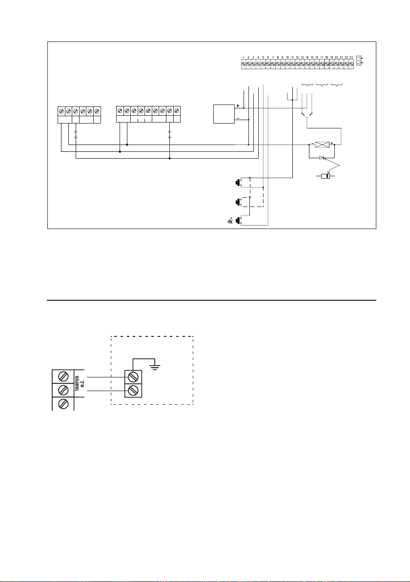
DA-2800 OR DA-2801
(DECODER)
N.O.
TAMPER
COM
COM
GND(-)
N.C.
N.C.
DOOR SENS
O/P 1 INHIB
INT. LOCK
DU OUT
DOOR BELL IN
EG IN
DATA I/O
KEYPAD PWR
GND(-)
12-24V DC
AR-2802/06/07/09
AUXILIARY READER OR
KEYPAD-READER
DATA
TAMPER
( + ) ( – )
12-24V DC
LED
I/O
N.C.
DK-2882
( + ) ( – )
12-24V DC
(SERVER)
OUTPUT 1
654321
987
654321
OUTPUT
EGINDATA
N.OCONN.C
2
I/O
(–) COMMON GND
(+) POWER SUPPLY
DATA I/O BUS
12-24V DC
POWER
SUPPLY
AD-1312 OR AP-960
DIGITAL KEYPAD
EGRESS BUTTON
MORE EGRESS
BUTTON CAN BE
CONNECTED IN
PARALLEL
DOOR BELL
BUTTON
(
-
)
N.O.
(-)
N.O.
(
-
)
N.O.
OUTPUT 1 OUTPUT 2 OUTPUT 3
OUTPUT RELAY 1
N.C. N.O.
N.O. Output for Fail-secure Lock
N.C. Output for Fail-safe Lock
ELECTRIC LOCK
1N4004
43. APPLICATION HINTS FOR THE AUXILIARY
TERMINALS
a) TAMPER N.C.
LINK UP
-----------------------
ALARM O/P
KEY ACT O/P
N.O.
N.O.
COM
N.C.
CATHODE
68
ALARM CONTROL PANEL
24 HOUR N.C.
PROTECTION
ZONE
The tamper switch is Normally Closed while the keypad
is secured on gang box. It is open when the keypad is
removed from the gang box. To prevent sabotage, connect
these terminals in series with a 24 hour N.C. protection
zone of an alarm system if required.

b) DOOR SENS
• Door Auto Relock -- The system will immediately relock
MAGNETIC
DOOR
SWITCH
the door after a valid access has been gained to prevent
“tailgate” entries.
• Door Forced-open Alarm -- The keypad will generate
alarm instantly if the door is forced to open. Enable the
function at Location 80.
• Door Propped-up Alarm -- The keypad will generate
alarm if the door is left open longer than the pre-set
delay time. Enable the function at Location 81.
With the help of a Normally Closed door position sensor
(usually a magnetic door switch) on the door to set up the
following functions:
• Inter-lock Control -- When the door is open,the
interlock output of the keypad will give a (-) command to
stop the other keypad in an inter-lock system.
• Door Opening Alarm -- Door Opening Alarm is
designed for the emergency door only. It is always given
when the door is opened unless a valid user code or
card is used prior to the door is opened. Enable the
function at Location 91.
c) ALARM OUTPUT -- SET THE “K OR A” JUMPER TO “A”
OR
ALARM CONTROL PANEL
24 HOUR N.O.
PROTECTION
ZONE
LED
LOW POWER
PIEZO BUZZER
The Alarm Output switches to (-) ground in door forced to open or the door open after Egress Delay. You may use it
to turn ON an LED lamp and/ or a small buzzer to notify a guard; or connect it to a 24 hour Normally Open protection
zone of an alarm system. See Location 80 and Location 91 for more information about these functions.
• Only one connection option is recommended. Make sure that the sink current does not exceed the maximum rating
of 100mA.
69

d) KEY ACTIVE -- SET THE “K OR A” JUMPER TO “K”
LOW POWER
LED
PIEZO BUZZER
(a) (b)
OR
ISOLATION RELAY
N.O. RELAY
CONTACT
The Key Active Output switches to (-) ground for 10 seconds whenever a key is touched. You may use it to turn ON
an LED lamp and /or a small buzzer to notify a guard; or to energize a relay to switch ON lights or trigger an CCTV
Camera to start recording.
• Make sure that the relay for switching ON lights has high enough isolation between high voltage and low voltage
to prevent damage of the keypad.
• Only one connection option is recommended. Make sure the sink current does not exceed the maximum rating of
100mA.
• External power supply and isolation relay are strictly necessary in driving high power device, such as lights.
e) DURESS OUTPUT
ALARM CONTROL PANEL
OR
LED
LOW POWER
PIEZO BUZZER
24 HOUR N.O.
PROTECTION
ZONE
The Duress Output switches to (-) ground when duress code is entered. You may use it to turn ON an LED lamp and/
or a small buzzer to notify a guard; or connect it to a 24 hour Normally Open protection zone of an alarm system.
• Only one connection option is recommended. Make sure that the sink current does not exceed the maximum rating
of 100mA.
70

f) OUTPUT 2
Shunting an N.C. Zone
TO PROTECTION ZONE OF AN
ALARM CONTROL PANEL
N.C.
N.C. MAGNETIC CONTACT
• Put Output 2 jumper to N.O.
• Use the Normally Open (N.O.) output contact to shunt a Normally Closed (N.C.) protection zone of an alarm system.
• Set output contact to Start / Stop Mode (Programming Option 52, Output Mode=0).
Alarm System Arm-Disarm Control
REMOTE
ARM-DISARM
CONTROL NO.
OR N.C.
ALARM CONTROL PANEL
• Use the (N.O.) or (N.C.) output contact to make arm-disarm control of an alarm system.
• Consult your alarm control panel manual for the appropriate output contact for arm-disarm control.
• Usually set output 2 to Momentary mode (Programming Option 521, Location 52, Output Mode=1) for multi station
systems and Start / Stop mode (Programming Option 520, Location 52, Output Mode=0) for single station systems.
g) OUTPUT 3 -- DOOR BELL BUTTON (DK-2882B OR D ONLY)
(OPTIONAL)
ELECTRONIC
DOOR CHIME
N.O.
DOOR
BELL
The output 3 of the DK-2882B or D is prepared for
triggering a low power door chime. DO NOT use it as a
high voltage power path for a door bell. The maximum
power rating of the contact is 24V DC/1 Amp.
Connect the N.O. output contact in parallel with the door
bell button.
71

44. AUXILIARY INFORMATION
DRY CONTACT
A dry contact means that no electricity is connected to it. It is prepared for free connections. The Relay Output contacts
provided in this keypad system are dry contacts.
N.C.
Normally Closed, the contact is closed circuit at normal status. It is open circuit when active.
N.O.
Normally Open, the contact is open circuit at normal status. It is closed circuit when active.
TRANSISTOR OPEN COLLECTOR OUTPUT
An open collector output is equivalent to a Normally Open (N.O.) contact referring to ground similar to a relay contact
referring to ground. The transistor is normally OFF, and its output switches to ground (-) when active. The open
collector can only provide switching function for small power but it is usually good enough for controlling of an alarm
system. The Duress, Inter-lock and Key Active/Alarm Outputs of the keypad are open collector outputs.
OPEN COLLECTOR
OUTPUT ----
Output switches to
ground when activated
EQUIVALENT
N.O. CONTACT
OUTPUT ----
Output switches to
ground when activated
45. CARE AND CLEANING
• This product does not require servicing. Repair work must be done by a specialist technician.
• Use a dry, clean and soft cloth to clean the product. The cloth can be dampened with water to clean the keypad
on the code lock.
• Never use aggressive detergents, rubbing alcohol or other chemical solutions, as these may damage the housing
or cause the product to malfunction.
• Use a dry, lint-free cloth to clean the product. Do not press too hard on the housing, as this can lead to scratch
marks.
72

46. DECLARATION OF CONFORMITY (DOC)
Conrad Electronic SE, Klaus-Conrad-Straße 1, D-92240 Hirschau hereby declares that this product conforms to the
2014/53/EU directive.
Click on the following link to read the full text of the EU declaration of conformity:
www.conrad.com/downloads
Select a language by clicking on a ag symbol and enter the product order number in the search box. You
can then download the EU declaration of conformity in PDF format.
47. FCC CAUTION
Any changes or modications not expressly approved by the party responsible for compliance could void the user‘s
authority to operate this equipment.
This device complies with Part 15 of the FCC Rules. Operation is subject to the following two conditions:
• This device may not cause harmful interference, and
• this device must accept any interference received, including interference that may cause undesired operation.
This device and its antenna(s) must not be co-located or operating in conjunction with any other antenna or transmitter.
NOTE:
This equipment has been tested and found to comply with the limits for a Class B digital device, pursuant to Part
15 of the FCC Rules. These limits are designed to provide reasonable protection against harmful interference in a
residential installation. This equipment generates, uses and can radiate radio frequency energy and, if not installed
and used in accordance with the instructions, may cause harmful interference to radio communications. However,
there is no guarantee that interference will not occur in a particular installation.
If this equipment does cause harmful interference to radio or television reception, which can be determined by turning
the equipment off and on, the user is encouraged to try to correct the interference by one or more of the following
measures:
• Reorient or relocate the receiving antenna.
• Increase the separation between the equipment and receiver.
• Connect the equipment into an outlet on a circuit different from that to which the receiver is connected.
• Consult the dealer or an experienced radio/TV technician for help.
48. DISPOSAL
Electronic devices are recyclable waste and must not be disposed of in the household waste. At the end of
its service life, dispose of the product in accordance with applicable regulatory guidelines.
You thus fulll your statutory obligations and contribute to the protection of the environment.
73

49. TECHNICAL DATA
a) ITEM NO. 1582599
Code lock
Operating voltage .........................12–24 V/DC (automatic voltage adjustment)
Current consumption ....................75 mA (quiescent) max. 145 mA (3 active relays)
Protection rating ...........................IP66
Output relay 1 (NC NO) ................max. 5 A / 24 V DC
Output relay 2 (NC NO) ................max. 1 A / 24 V DC
Output relay 3 (NO) ......................max. 1 A / 24 V DC
Number of codes ..........................Over 100 million codes (4 to 8 digits long)
Unlock by ......................................User code, transponder card or user code and transponder card combined
Connection standard ....................Wiegand output (for transponder card or user code)
Transmission power......................35 dB/μA/m
Mounting location .........................Indoors and outdoors
Transponder card frequency.........125 kHz
Operating/storage conditions ........-20 to +70 °C, 5 to 95 % relative humidity, non-condensing
Dimensions (H x W x D) ...............156 x 103 x 50/70 mm
Weight ..........................................approx. 1030 g
Control unit
Operating voltage .........................12–24 V/DC (automatic voltage adjustment)
Current consumption ....................65 mA (quiescent) max. 100 mA (3 active relays)
Operating/storage conditions ........-20 to +70 °C, 5 to 95 % relative humidity, non-condensing
Sound pressure level ....................94 dB at approx. 30 cm distance
Switch delay .................................5 seconds
Safety alarm .................................3 minutes
Mounting location .........................Dry indoor locations
Dimensions (H x W x D) ...............33 x 120 x 87 mm
Weight ..........................................approx. 178 g
74

b) ITEM NO. 1582600
Code lock
Operating voltage .........................12–24 V/DC (automatic voltage adjustment)
Current consumption ....................75 mA (quiescent) max. 145 mA (3 active relays)
Protection rating ...........................IP66
Output relay 1 (NC NO) ................max. 5 A / 24 V DC
Output relay 2 (NC NO) ................max. 1 A / 24 V DC
Output relay 3 (NO) ......................max. 1 A / 24 V DC
Number of codes ..........................Over 100 million codes (4 to 8 digits long)
Unlock by ......................................User code, transponder card or user code and transponder card combined
Connection standard ....................Wiegand output (for transponder card and/or user code)
Transmission power......................35 dB/μA/m
Mounting location .........................Indoors and outdoors
Transponder card frequency.........125 kHz
Operating/storage conditions ........-20 to +70 °C, 5 to 95 % relative humidity, non-condensing
Dimensions (H x W x D) ...............151 x 98 x 42 mm
Weight ..........................................approx. 460 g
Control unit
Operating voltage .........................12–24 V/DC (automatic voltage adjustment)
Current consumption ....................65 mA (quiescent) max. 100 mA (3 active relays)
Operating/storage conditions ........-20 to +70 °C, 5 to 95 % relative humidity, non-condensing
Sound pressure level ....................94 dB at approx. 30 cm distance
Switch delay .................................Every 5 seconds
Safety alarm .................................3 minutes
Mounting location .........................Dry indoor locations
Dimensions (H x W x D) ...............33 x 120 x 87 mm
Weight ..........................................approx. 178 g
75

This is a publication by Conrad Electronic SE, Klaus-Conrad-Str. 1, D-92240 Hirschau (www.conrad.com).
All rights including translation reserved. Reproduction by any method, e.g. photocopy, microlming, or the capture in
electronic data processing systems require the prior written approval by the editor. Reprinting, also in part, is prohibited.
This publication represent the technical status at the time of printing.
Copyright
2018
by Conrad Electronic SE.
1582599_600_V1_0918_02_mxs_m_en_part 1
 Loading...