


Operating instructions
GB
Digital room thermostat
Item No. 1385634

Table of contents
1. Introduction .........................................................................4
2. Explanation of symbols .....................................................5
3. Intended use ........................................................................6
4. Scope of delivery ................................................................7
5. Features ...............................................................................8
6. Safety information .............................................................8
a) Persons/Product ..............................................................8
b) Batteries ........................................................................ 11
7. Installation ......................................................................... 13
8. Inserting or replacing the batteries .................................17
9. Commissioning and operation ........................................18
a) Switching on/off ...........................................................18
b) Selection of the operating function.............................19
c) Manual operation ......................................................... 19
d) AUTO mode ..................................................................20
e) PROGRAMME mode ....................................................21
f) Frost protection function .............................................22
GB
Page
2

Page
10. Settings ..............................................................................23
a) Temperature calibration ...............................................23
b) Time setting ..................................................................24
c) Setting the economic temperature .............................24
d) PROGRAMME setting ..................................................25
11. Setup ..................................................................................26
12. Error messages display ....................................................30
13. Maintenance and cleaning ...............................................31
14. Disposal .............................................................................33
a) Product ..........................................................................33
b) Batteries ........................................................................33
3

1. Introduction
Dear Customer,
thank you for purchasing this product.
This product complies with the statutory national and European requirements.
To maintain this status and to ensure safe operation, you as
the user must observe these operating instructions!
These operating instructions are part of this product.
They contain important notes on commissioning and
handling. Also consider this if you pass on the product
to any third party.
Therefore, retain these operating instructions for refe-
rence!
All company names and product names are trademarks of
their respective owners. All rights reserved.
If there are any technical questions, please contact:
International: www.conrad.de/kontakt
United Kingdom: www.conrad-electronic.co.uk/contact
4
2. Explanation of symbols
The lightning symbol is used when your health is at risk.
This symbol points out particular dangers associated
with handling, function or operation.
The arrow symbol indicates special advice and opera-
ting information.
Observe the operating instructions!
5

3. Intended use
The digital room thermostat serves automatic switching of a
connected end device, according to the set or programmed
times or the set temperatures.
The room thermostat must only be operated with commercial batteries of type AAA/Micro.
It is intended for indoor use only. Do not use it outdoors.
Contact with moisture must be avoided under all circumstances.
The safety notes and all other information in these operating
instructions always have to be observed!
Any use other than that described above can damage the
product and may involve additional risks such as short circuit, fire, electric shock, etc. No part of this product must be
modified or converted!
This product complies with the statutory national and European requirements. All company names and product
names are trademarks of their respective owners. All rights
reserved.
6
4. Scope of delivery
• Room thermostat
• 2x AAA batteries
• 2x screws
• Operating instructions
Up-to-date operating instructions:
1.
Open www.conrad.com/downloads in a
browser or scan the displayed QR code.
2.
Select document type and language and
enter the item number into the search field.
After submitting the query you can download displayed records.
7

5. Features
• Manual mode; AUTO mode; PROGRAMME mode
• Display
• Programmable thresholds
• Frost protection function
• Lock function
6. Safety information
The guarantee/warranty will expire if damage is in-
curred resulting from non-compliance with the operating instructions! We do not assume any liability for
consequential damage!
We do not assume any liability for property damage and
personal injury caused by improper use or non-compliance with the safety instructions. In such cases the warranty/guarantee is voided.
a) Persons/Product
• The unauthorized conversion and/or modification of
the product is inadmissible for safety and approval
reasons (CE). Do not disassemble it, except for the
battery change described in these instructions.
8

• The product is not a toy. Keep the product away from
children. Therefore, be particularly careful when children are present.
• The product must not be exposed to extreme temperatures, strong vibration, strong moisture or
strong mechanical strain. The product must not become damp or wet. Contact with moisture must be
avoided under all circumstances.
• Do not use the room thermostat inside of rooms or
in bad ambient conditions where flammable gases,
vapours or explosive dust may be or are present!
There is a danger of explosion!
• Do not attach any objects to the product. Never cover
the room thermostat. There is a danger of fire.
• The manufacturer or supplier does not assume any
responsibility for incorrect displays or the consequences resulting from incorrect displays.
• Servicing or repair must only be carried out by a specialist.
• Never use the product immediately after it has been
taken from a cold into a warm environment. The condensation generated may destroy the product. First
let the product reach room temperature before using
it. This may take several hours.
9

• The following unfavourable conditions are to be
avoided at the place of use and during transport:
- Dust or flammable gases, fumes or solvents
- Strong vibration, impact or blows
• Handle the product with care. It can be damaged by
impact, blows or when dropped even from a low
height.
• If it can be assumed that safe operation is no longer
possible, the device must be turned off and precautions are to be taken to ensure that it is not used unintentionally. Then have the product inspected by a
specialist.
It must be assumed that safe operation is no longer
possible, if:
- the device shows visible damage
- the device no longer functions properly
- the device has been stored under unfavourable
- it has been subjected to severe stress during trans-
• Do not leave the packaging material lying around
conditions for an extended period of time
port
carelessly as it can become a dangerous toy for children.
10

• In commercial institutions, the accident prevention
regulations of the Employer’s Liability Insurance Association for Electrical Systems and Operating Materials are to be observed.
• If you have questions which remain unanswered by
these operating instructions, please contact us or another expert.
b) Batteries
• Batteries have no place in the hands of children.
• Do not leave any batteries lying around openly. There
is a risk of batteries being swallowed by children or
pets. If swallowed, consult a doctor immediately.
• Always observe the correct polarity (plus/+ and minus/-) when inserting the batteries.
• Leaking or damaged batteries may cause chemical
burns to skin when touched. Use adequate protective gloves in this case.
• Batteries must not be short-circuited, taken apart or
thrown into fire. There is a danger of explosion!
• Do not recharge normal, non-rechargeable batteries;
danger of explosion!
• Never mix batteries with different charging conditions or from different manufacturers.
11

• If not used for a longer period (e.g. in case of storage), remove the inserted batteries. If batteries are
too old, they may leak and cause damage to the
product, which leads to the cancellation of the warranty/guarantee!
Read the “Disposal” chapter for instructions on envi-
ronmentally sustainable disposal of batteries.
12

7. Installation
The room thermostat must only be installed by a qual-
ified specialist. Installation must only be performed according to the applicable local provisions.
The room thermostat must not be installed near any
windows, doors, heat sources or ventilation openings.
Also avoid installation in locations where the device is
exposed to direct sunlight. This may falsify the measured room temperature. Keep a distance of approx. 1.5
m for this.
Never cover the room thermostat with any other ob-
jects.
The device is only suitable for vertical wall mounting.
We recommend a mounting height starting at approx.
1.5 m. Only install the device on a stable basis, e.g. masonry.
Observe the max. connection value of the room ther-
mostat; see technical data. The installed relay is potential-free.
The controller must only be installed when powered down.
For this, power down the electrical mains supply that is connected to the relay of the room thermostat (circuit protection
and FI-switch off) and secure it against unauthorised reactivation!
13

Check the mains supply line for voltage-freeness. Ensure
that no present electrical or water lines are damaged during
installation.
The same applies, if only low voltage is to be supplied
through the relay, since this may cause short circuit at installation!
Remove the battery holder at the bottom of the device. Turn
the housing screw at the bottom of the controller out only
until the upper shell of the room thermostat can be removed.
Do not turn the housing screw out entirely. There is the danger of losing the housing screw and the square nut. Now
pull the upper shell of the controller off of the base plate.
The base plate is attached on a recessed socket with the
two enclosed screws. The base plate has four indentations
for attachment for this purpose. Break out the two required
attachment openings with a suitable tool. Route the mains
line through the mains line opening of the base plate. Attach
the base plate on the recessed socket with the two enclosed
screws (figure 1). Check for tight fit of the base plate.
Strip 5 mm of the cable insulation. Connect the supply line
of the end device to the screw terminal NO (1) or NC (3) and
COM (2).
14

The installed relay is potential-free. The connection ex-
ample shows the connection to mains voltage 230V/
AC. Observe the maximum contact resilience; see chapter “Technical Data” and the operating instructions of
the device that is to be controlled via the room thermostat, on how to set up the circuits.
1 = Normally open contact (NO)
2 = COM (Common)
3 = Normally closed contact (NC)
L 230 V/AC, 50-60 Hz
E.g. recircula-
tion pump
Example
15

Push the upper shell onto the base plate (figure 2). Make
sure that the supply lines are not crushed or damaged by
this. The upper shell is now attached to the base plate again
with the housing screw (figure 3).
The room thermostat must only be operated with the
correctly attached and screwed-on upper shell. If the
upper shell is missing or wrongly installed, there is a
danger to life from electric shock!
16

8. Inserting or replacing the batteries
• Pull the battery holder from the bottom of the device.
• Insert the two batteries of type AAA (Micro) in the correct
polarity. Observe the marking in the battery compartment
holder.
• Return the battery holder to the room thermostat.
• Use only alkaline batteries.
Use only batteries of the specified type. Use alkaline
batteries for the longest operating duration.
The product is only approved for operation with 2x 1.5 V
AAA-batteries (Micro). No other energy supply must be
used.
Replace the batteries when the battery display flashes.
17

9. Commissioning and operation
Observe Chapter “Safety information”!
PROGRAMME Mode
AUTO Mode
Time/temperature display
Symbols for switching times
Symbol for time setting
Display off
Display SET
Manual mode
Frost protection function
Icon
Display Celsius
Display AM / PM
ECONOMIC temperature
Display calibration
LOCK function
Heating/consumer on
Battery display
a) Switching on/off
Push the button OK to switch on the room thermostat.
Push and hold the button OK to switch off the room thermostat (display OFF).
18

b) Selection of the operating function
Switch on the room thermostat. Push the button OK repeatedly until the desired operating function (manual mode;
frost protection function; AUTO mode; PROGRAMME mode)
is displayed.
c) Manual operation
Manual operation serves constant increase or reduction of
the room temperature. In manual mode, the symbol is
displayed. The factory setting for manual mode is 20 °C.
The temperature value set in the factory can be changed.
For this, push the button plus + or -.
Push and hold the plus + or minus - button of the tem-
perature setting. The temperature setting is now accelerated.
The set temperature is kept until the mode is changed.
The device will then switch back to the factory setting of
20 °C.
19

d) AUTO mode
The following values are set ex works for AUTO mode.
00:00——06:00 Temperature setting: 18 °C
06:00——08:00 Temperature setting: 20 °C
08:00——18:00 Temperature setting: 16 °C
18:00——22:00 Temperature setting: 20 °C
22:00——24:00 Temperature setting: 18 °C
In AUTO mode, the symbol “AUTO” is displayed.
The temperature value set ex works can be changed for
the current heating or reduction phase.
Briefly push the plus + or minus - button. The tempera-
ture display will change from the current room temperature to the set temperature.
Now push the plus + or minus - button to change the set
temperature.
Push and hold the plus + or minus - button of the tempe-
rature setting. The temperature setting is now accelerated.
The set temperature is retained until a different mode
is activated or the next heating or reduction phase is
reached. The device will then switch back to the factory
settings.
20

e) PROGRAMME mode
Set the switching times and temperatures as described in
item “PROGRAMME setting”. Then switch the room thermostat to PROGRAMME mode. The symbol “AUTO PROG” is
displayed.
The programmed temperature value can be changed manually for the current heating or reduction phase.
Briefly push the plus + or minus - button. The temperature
display will change from the current room temperature to
the set temperature.
Now push the plus + or minus - button to change the set
temperature for this switching period.
Push and hold the plus + or minus - button of the temperature setting. The temperature setting is now accelerated.
The set temperature is retained until a different mode is activated or the next heating or reduction phase is reached. The
device will then switch back to the programmed temperature
as described in item “PROGRAMME setting”.
21

f) Frost protection function
When the frost protection function is active, the room thermostat will prevent the room temperature to drop below 5
°C. The frost protection function thus prevents freezing of liquid-based heatings and pipes. The frost protection temperature is fixed at 5 °C in the factory and cannot be changed.
When the thermostat is in the frost protection function, the
symbol will be displayed.
22

10. Settings
The thermostat must be on. Push the buttons SET and OK at
the same time to get to the setting mode. The relay switches
off in setting mode.
Change the values with the buttons “+” and “-”. Keep the respective button pressed for quick adjustment.
If you do not push any button for approx. 60 seconds, the
settings made until then are saved and setting mode is left.
Push the OK button to save the setting and to leave the setting mode.
a) Temperature calibration
This function permits calibrating the thermostat based on a
reference value or adjusting it to other thermostats.
or
Push the OK
Push SET and OK buttons
at the same time
Push plus or minus button
for setting
The setting is made in steps of 0.1 °C (setting range -3°C to
+3°C).
button for
confirmation
23

The settings are only applied with the next temperature
measurement of the thermostat. This may take a while.
b) Time setting
The time is set in 12-hour format (midnight to noon = AM /
noon to midnight = PM).
or or
Push SET
Push plus + or
minus buttons to set the
hours
button
Push plus + or
minus - buttons
to set the
minutes
Push OK
button
to
confirm
Push SET and OK
buttons
at the same time
Push SET
button
c) Setting the economic temperature
Push SET
Push SET and OK buttons
at the same time
button 3x
The setting is made in steps of 0.1 °C (setting range 5 °C to
+35 °C/ factory setting 16 °C).
or
Push plus + or minus buttons to set the
temperature
Push OK
button
to
confirm
24

d) PROGRAMME setting
Set the desired start, end times and temperatures for the programme mode here. The connected consumer is switched
on and off by remote control after this time. Two switching
periods can be programmed.
or
Push the plus + or minus button to set the minutes (P1)
or
Repeat the input for the
hours and minutes
setting for P2
or
Keep SET and OK
buttons pushed for
3 seconds
Repeat the
setting for
P3-P4
Push the OK
button for
confirmation
or
Push plus + or minus buttons to set the hours (P1)
Push the plus + or minus button for the temperature
setting of P1/P2
P1: Start of the first switching period (temperature-con-
trolled)
P2: End of the first switching period (temperature-controlled)
P3: Start of the second switching period (temperature-con-
trolled)
P4: End of the second switching period (temperature-con-
trolled)
After the programmed switching times P1/P2 and P3/P4, the
room temperature is adjusted to the Economic temperature.
25

11. Setup
To switch to the setup settings, the thermostat must be in
the position OFF.
Keep SET and OK
buttons pushed
for 5 seconds
or
To set the
parameters
Switch
to the
next
setting
or
To set the
parameters
Push the OK
button
to confirm
and to
switch to
manual
mode
Change the values with the buttons “+” and “-”. Keep the respective button pressed for quick adjustment.
If you do not push any button for approx. 60 seconds, the
settings made until then are saved and setting mode is left.
Push the OK and SET buttons for 5 seconds to save the input
and switch to OFF mode.
26
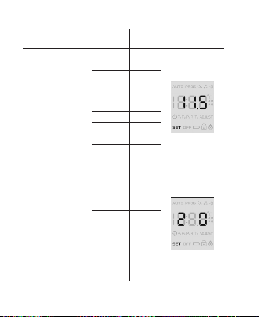
Order Descrip-
2
1
tion
Difference
between
activation
and deac-
tivation
tempera-
ture
(Switch-
ing
hystere-
sis)
Display of
temper-
ature
or time
in the
display
Note Setting
options
Factory
setting
Temper-
ature
display
(factory
setting)
Switch-
ing
between
tempera-
ture (8s)
and time
display
(2s)
Display
0 °C
0.2 °C
0.5 °C
1.0 °C
1.5 °C
2.0 °C
2.5 °C
3.0 °C
3.5 °C
4.0 °C
0
1
27
28
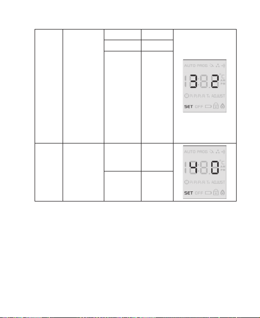
3
4
Switching
condition
of the
relay
(contact
NO and
COM) in
the OFF
condition
Lock func-
tion (key
lock)
open 0
closed 1
The relay
switch-
es at a
room
temper-
ature
below
5 °C
(factory
setting)
Off
(factory
setting)
On 1
2
0

5
6
Max.
adjustable
room
tempera-
ture
Factory
Setting
10°C -
35°C
(adjust-
able in
steps of
0.5°C /
factory
setting
35°C)
Set
parameters to
factory
setting
Indi-
vidual
parame-
ters to be
main-
tained
(setting
ex
works)
Display
at 35°C
0
1
29

12. Error messages display
The display flashes when the room temperature drops below 0 °C or climbs above 45 °C.
30

13. Maintenance and cleaning
Regularly check the technical safety of the device, e.g. for a
damaged casing.
If you have reason to believe that the device can no longer be
operated safely, disconnect it immediately and make sure it
is not operated unintentionally.
It must be assumed that safe operation is no longer possible
if:
• the device shows visible damage
• the device is longer working
• the device has been stored under unfavourable conditions
for an extended period of time or
• the device has been subjected to heavy stress during transport.
Always observe the following safety information before
cleaning or servicing the device:
Live components may be exposed if cover is opened.
The device must be disconnected from all power sourc-
es before any servicing or repair work is carried out.
Capacitors inside the device may still carry voltage even
though they have been disconnected from all power
sources.
31

Only qualified experts familiar with the hazards involved
and the relevant regulations must perform repairs.
The product requires no servicing apart from replacing the
rechargeable battery. Servicing or repair must only be carried out by a specialist or specialist workshop. Therefore,
never open it (except for the procedures described in these
operating instructions for insertion/replacing the batteries).
A dry, soft and clean cloth is sufficient for cleaning.
Do not put too much pressure on the display; this can cause
scratch marks, failures of the display or even destroy the
display.
Dust can easily be removed with a long-hair, soft and clean
brush and a vacuum cleaner.
Never use any aggressive cleaning agents, cleaning alcohol
or other chemical solutions, since these may damage the
casing (discolouration) or even impair function.
32

14. Disposal
a) Product
Electronic devices are recyclable waste and must
not be disposed of in household waste!
Dispose of the product according to the applicable
Remove any inserted batteries and dispose of them
b) Batteries
You as the end user are required by law (Battery ordinance)
to return all used batteries. Disposing of them in the household waste is prohibited!
You can return used batteries free of charge at the official
collection points of your community, in our stores, or wherever batteries are sold!
statutory provisions at the end of its service life.
separately from the product.
Batteries that contain any hazardous substances
are labelled with the adjacent icon to indicate
that disposal in domestic waste is forbidden. The
descriptions for the respective heavy metals are:
Cd=cadmium, Hg=mercury, Pb=lead (the names
are indicated on the battery, e.g. below the rubbish
bin symbol shown on the left).
33

You thus fulfil your statutory obligations and contribute to
the protection of the environment.
15. Technical data
Operating voltage ..................... 3.0 V/DC (2x 1.5 V micro bat-
Switching output ...................... max. 230 V/AC / 8 A (ohmic
Temperature resolution. ..... ..... 0.1 °C
Temperature setting range ....... 5 °C to 35 °C (0.1 °C steps/ad-
Switching hysteresis ................ 0 °C to 4.0 °C (adjustable)
Display range
Integrated measuring sensor ... NTC 1%
Ambient conditions .................. temperature 0 °C to +40 °C,
Dimensions (H x W x D)............ 86 x 100 x 20 mm
34
teries, type AAA)
load) / 3.5 A (inductive load)
/ relay potential-free / NO a.
NC contact
justable)
humidity 20% to 85% relative, non-condensing

35

o Legal Notice
This is a publication by Conrad Electronic SE, Klaus-Conrad-Str. 1, D-92240 Hirschau
(www.conrad.com).
All rights including translation reserved. Reproduction by any method, e.g. photocopy, microfilming, or the capture in electronic data processing systems require the prior written
approval by the editor. Reprinting, also in part, is prohibited. This publication represent the
technical status at the time of printing.
© Copyright 2016 by Conrad Electronic SE. V3_0516_02/VTP
 Loading...