

Page 1

DNX Series Multiservice Cross-Connect
Quick Install & Setup Guide
Inside ...
Provides instructions for:
Inspecting equipment
Part descriptions
Hardware installation/setup
Powering up the system.
DOC-001-11001
Revision 006
February 2008
Page 2

Copyright © 2006 Sycamore Networks, Inc. All Rights Reserved.
Sycamore assumes no responsibility for the accuracy of the information presented, which is
subject to change without notice.
Sycamore Networks®, Sycamore, SN 3000, SN 9000, SN 16000, DNX-1u, DNX-11, DNX-88,
S-DNX, PSX-5300, SPS-1000, IAB-3000, OM1000, OM4000, ENvision, ENvision Plus,
BroadLeaf®, SILVX®, SilvxManager®, SilvxOSS®, SilvxSource®, SILVX InSight®, and
SOLAR® are trademarks of Sycamore Networks, Inc. All other trademarks, service marks,
registered trademarks, or registered service marks may be the property of their respective
owners. The Sycamore Networks, Inc. trademarks may not be used in connection with any
product or service that is not Sycamore Networks' in any manner that is likely to cause
confusion among customers or in any manner that disparages or discredits Sycamore
Networks, Inc.
This document contains information that is the property of Sycamore Networks, Inc. This
document may not be copied, reproduced, reduced to any electronic medium or machine
readable form, or otherwise duplicated, and the information herein may not be used,
disseminated or otherwise disclosed, except with the prior written consent of Sycamore
Networks, Inc.
Page 3

Foreword
This issue of the Digital Network Exchange Series (DNX) Quick Install & Setup Guide contains
instructions for inspecting equipment, part descriptions, hardware installation/setup, and powering up the system. For more detailed information, refer to the DNX-11 Reference and User’s
Guide or the DNX-88 Reference and User’s Guide. The following features that have been
added since the last update of this document:
• Added new views of DNX-11 rear with added AC power restraints.
• Removed DNX-4 information (product discontinued)
• Added grounding strap connection for the PSX-5300.
Note: Screens shown in this document still reflect Eastern Research, as the software has not
yet been rebranded as Sycamore Networks.
Guide Summary
This Quick Install Guide is designed to provide instructions for mounting a DNX or PSX chassis
into a rack, installing power supplies, innstalling the System Manager Controller card set,
installing interface and application module sets, and installing the N+1 Protection Switch.
Instructions for logging into the DNX are also furnished. Please read it through carefully and
completely to become familiar with its contents and instructions. This material is targeted to
qualified telecommunications engineering and operations personnel and is intended to be a
supplemental technical aid to complement the DNX-related tra ining programs a vailable through
Sycamore Networks Education Services.
DOC-001-11001 (Rev. 006) i DNX Quick Install & Setup Guide
Page 4
Conventions
To enhance the usability and clarity of this Guide, the following conventions are used to
delineate specific types of information that are of importance to the user:
Warnings
Warnings are used to present information or describe conditions that if not observed could
potentially result in bodily injury:
Figure 1: Sample Warning
If there is already a power supply installed and power is a pplied, use extreme
care when accessing the inside of the unit.
Cautions
Cautions are used to highlight a condition or action that could result in equipment damage or
loss of traffic:
Foreword
WARNING
Figure 2: Sample Caution
Always use the card ejector to seat and unseat a module. Pushing or pulling on
the edge of the circuit card may cause damage to the module.
Notes
Notes are used to point out something of special interest or importance to the user. Failure to
read the note will not result in physical harm to the user, equipment or traffic:
Figure 3: Sample Note
Note: When powering the DNX-1 1 from a DC power sour ce, use two sep arate fuse p anels or
ESD Cautions
ESD Cautions remind the user that a particular module is sensitive to Electrostatic Dischar ge:
Figure 4: Sample ESD Caution
CAUTION
a fuse panel with redundant (A and B) fuse positions.
ESD CAUTION
DNX system components contain electrostatic-sensitive circuit s.
Before handling DNX components, wear an anti-static wrist
strap connected to frame ground to prevent damage to circuits
from electrostatic discharge.
DOC-001-11001 (Rev. 006) ii DNX Quick Install & Setup Guide
Page 5

Revision Control
The information contained in this Guide is the most current availa ble at the time of its
publication. As features evolve or corrections warrant, revisions to this guide will be produced
and made available to customers via the Sycamore Networks website at
www.sycamorenet.com. Please refer to the Document Number and Revision Level noted in the
footer of this guide to ensure that the latest version is being utilized.
Quality Commitment
Sycamore Networks, Inc., as an ISO-9001 registered firm, is committed to customer value and
the lasting quality of all its products, services and documentation. As an integral part of its continuous improvement program, Sycamore Networks is actively seeking feedback on the overall
quality, usability and accuracy of this guide. Please forward any comments or suggestions
directly to the Sycamore Networks Technical Publication staff at [email protected].
Thank you for your patronage and assistance.
Technical Assistance Center
Sycamore Networks Technical Assistance Center (TAC) provides technical support 24 hours a
day, 7 days a week (24 x 7). To contact the TAC:
Foreword
E-mail: [email protected]
Telephone support 24 x 7:
• 1-877-526-2321 (1-877-LAMBDA1) – toll-free in North America
• 0080005262321 – toll-free in Europe
• 1-978-250-3480 – toll call
All other calls, including sales and marketing information, call 1-978-250-2900
Education/Training Services
Sycamore Networks Education Services delivers focused, cost-effective education programs to
help you design, operate, and manage Sycamore Networks products in your network.
Visit the Customer Training web site at customertraining.sycamorenet.com for detailed information about education and training services.
DOC-001-11001 (Rev. 006) iii DNX Quick Install & Setup Guide
Page 6

Foreword
THIS PAGE INTENTIONALLY LEFT BLANK.
DOC-001-11001 (Rev. 006) iv DNX Quick Install & Setup Guide
Page 7

Table of Contents
Prior to Installation . . . . . . . . . . . . . . . . . . . . . . . . . . . . . . . . . . . . . . . . . 1
Inspect Shipment. . . . . . . . . . . . . . . . . . . . . . . . . . . . . . . . . . . . . . . . . . . . . . . . . . . . 1
To Inspect Equipment: . . . . . . . . . . . . . . . . . . . . . . . . . . . . . . . . . . . . . . . . . . . . . 1
Site Preparations. . . . . . . . . . . . . . . . . . . . . . . . . . . . . . . . . . . . . . . . . . . . . . . . . . . . 2
Required Tools and Cables . . . . . . . . . . . . . . . . . . . . . . . . . . . . . . . . . . . . . . . . . 2
Site Environmental Recommendations. . . . . . . . . . . . . . . . . . . . . . . . . . . . . . . . . 2
DNX-11 Installation . . . . . . . . . . . . . . . . . . . . . . . . . . . . . . . . . . . . . . . . . 3
Rack Mounting. . . . . . . . . . . . . . . . . . . . . . . . . . . . . . . . . . . . . . . . . . . . . . . . . . . . . . 3
19” EIA Flush Rack Mounting . . . . . . . . . . . . . . . . . . . . . . . . . . . . . . . . . . . . . . . . 3
23” EIA Flush Rack Mounting . . . . . . . . . . . . . . . . . . . . . . . . . . . . . . . . . . . . . . . . 4
23” EIA Center Rack Mounting . . . . . . . . . . . . . . . . . . . . . . . . . . . . . . . . . . . . . . . 5
19” Telco Flush Rack Mounting . . . . . . . . . . . . . . . . . . . . . . . . . . . . . . . . . . . . . . 6
23” Telco Flush Rack Mounting . . . . . . . . . . . . . . . . . . . . . . . . . . . . . . . . . . . . . . 7
23” Telco Center Rack Mounting . . . . . . . . . . . . . . . . . . . . . . . . . . . . . . . . . . . . . 8
Proper Grounding . . . . . . . . . . . . . . . . . . . . . . . . . . . . . . . . . . . . . . . . . . . . . . . . . . . 9
Grounding via Rack Mount . . . . . . . . . . . . . . . . . . . . . . . . . . . . . . . . . . . . . . . . . . 9
Grounding via Grounding Strap . . . . . . . . . . . . . . . . . . . . . . . . . . . . . . . . . . . . . . 10
Installing DNX-11 Power Supply Module(s). . . . . . . . . . . . . . . . . . . . . . . . . . . . . . . . 11
Internal Fuse/Wattage Requirements. . . . . . . . . . . . . . . . . . . . . . . . . . . . . . . . . . 11
DNX-11 AC Power. . . . . . . . . . . . . . . . . . . . . . . . . . . . . . . . . . . . . . . . . . . . . . . . . . . 12
AC Power Requirements . . . . . . . . . . . . . . . . . . . . . . . . . . . . . . . . . . . . . . . . . . . 12
AC Power Fuses. . . . . . . . . . . . . . . . . . . . . . . . . . . . . . . . . . . . . . . . . . . . . . . . . . 12
Connecting AC Power to a DNX-11 . . . . . . . . . . . . . . . . . . . . . . . . . . . . . . . . . . . 13
DNX-11 DC Power . . . . . . . . . . . . . . . . . . . . . . . . . . . . . . . . . . . . . . . . . . . . . . . . . . 14
DC Power Requirements . . . . . . . . . . . . . . . . . . . . . . . . . . . . . . . . . . . . . . . . . . . 14
DC Power Fuses. . . . . . . . . . . . . . . . . . . . . . . . . . . . . . . . . . . . . . . . . . . . . . . . . . 14
Connecting DC Power (-48VDC) to a DNX-11 . . . . . . . . . . . . . . . . . . . . . . . . . . . 15
Connecting the Talk Battery or Signal Battery . . . . . . . . . . . . . . . . . . . . . . . . . . . 17
Talk Battery & Signal Battery Fuses . . . . . . . . . . . . . . . . . . . . . . . . . . . . . . . . . . . 19
Installing the System Manager Controller . . . . . . . . . . . . . . . . . . . . . . . . . . . . . . . . . 20
To install an SMC II module into a DNX-11 chassis: . . . . . . . . . . . . . . . . . . . . . . 20
SMC II Module Jumper Configuration . . . . . . . . . . . . . . . . . . . . . . . . . . . . . . . . . . . . 21
Revision 0 and Revision 1 SMC II Modules . . . . . . . . . . . . . . . . . . . . . . . . . . . . . 21
Revision 0 and Revision 1 SMC II Modules - Jumper Placement. . . . . . . . . . . . . 22
Revision 2 SMC II Modules. . . . . . . . . . . . . . . . . . . . . . . . . . . . . . . . . . . . . . . . . . 23
Revision 2 SMC II Modules - Jumper Placement . . . . . . . . . . . . . . . . . . . . . . . . . 24
Installing Application & Interface Modules . . . . . . . . . . . . . . . . . . . . . . 25
To install application and interface modules into a DNX-11 chassis: . . . . . . . . . . 25
Connecting External Clocking . . . . . . . . . . . . . . . . . . . . . . . . . . . . . . . . 26
DOC-001-11001 (Rev. 006) vi DNX Quick Install & Setup Guide
Page 8

Table of Contents
PSX-5300 Installation . . . . . . . . . . . . . . . . . . . . . . . . . . . . . . . . . . . . . . . 27
Rack Mounting. . . . . . . . . . . . . . . . . . . . . . . . . . . . . . . . . . . . . . . . . . . . . . . . . . . . . . 28
Proper Grounding . . . . . . . . . . . . . . . . . . . . . . . . . . . . . . . . . . . . . . . . . . . . . . . . . 28
Grounding via Rack Mount . . . . . . . . . . . . . . . . . . . . . . . . . . . . . . . . . . . . . . . 28
Grounding via Grounding Strap . . . . . . . . . . . . . . . . . . . . . . . . . . . . . . . . . . . . 29
PSX-5300 DC Power. . . . . . . . . . . . . . . . . . . . . . . . . . . . . . . . . . . . . . . . . . . . . . . . . 30
DC Power Requirements . . . . . . . . . . . . . . . . . . . . . . . . . . . . . . . . . . . . . . . . . . . 30
DC Power Fuse. . . . . . . . . . . . . . . . . . . . . . . . . . . . . . . . . . . . . . . . . . . . . . . . . . . 30
PSX Module Installation and Cable Connection . . . . . . . . . . . . . . . . . . . . . . . . . . . . 31
Narrowband Cable Connections. . . . . . . . . . . . . . . . . . . . . . . . . . . . . . . . . . . . . . 32
Broadband Cable Connections. . . . . . . . . . . . . . . . . . . . . . . . . . . . . . . . . . . . . . . 33
Connecting N+1 Protection Switch DC Power (-48VDC) . . . . . . . . . . . . . . . . . . . 35
System Visual Inspection . . . . . . . . . . . . . . . . . . . . . . . . . . . . . . . . . . . . 37
Console Management Access . . . . . . . . . . . . . . . . . . . . . . . . . . . . . . . . 38
Connecting the Console . . . . . . . . . . . . . . . . . . . . . . . . . . . . . . . . . . . . . . . . . . . . 38
To Connect a Console: . . . . . . . . . . . . . . . . . . . . . . . . . . . . . . . . . . . . . . . . . . . . . 38
Logging into the DNX . . . . . . . . . . . . . . . . . . . . . . . . . . . . . . . . . . . . . . . . . . . . . . 40
System Security. . . . . . . . . . . . . . . . . . . . . . . . . . . . . . . . . . . . . . . . . . . . 41
Install IP Address. . . . . . . . . . . . . . . . . . . . . . . . . . . . . . . . . . . . . . . . . . . 42
Port IP Address Configuration . . . . . . . . . . . . . . . . . . . . . . . . . . . . . . . . . . . . . . . 42
Verifying Protection Switch Installation . . . . . . . . . . . . . . . . . . . . . . . . 44
Verify the Protection Switch Installation . . . . . . . . . . . . . . . . . . . . . . . . . . . . . 44
Verify the Protection Switch Profile Settings . . . . . . . . . . . . . . . . . . . . . . . . . . 48
Maintenance & Repair. . . . . . . . . . . . . . . . . . . . . . . . . . . . . . . . . . . . . . . 49
Routine Maintenance. . . . . . . . . . . . . . . . . . . . . . . . . . . . . . . . . . . . . . . . . . . . . . . . . 49
Equipment Repair and Return. . . . . . . . . . . . . . . . . . . . . . . . . . . . . . . . . . . . . . . . . . 49
Appendix A Regulatory Information . . . . . . . . . . . . . . . . . . . . . . . . . . . . . . . . . A-1
North America . . . . . . . . . . . . . . . . . . . . . . . . . . . . . . . . . . . . . . . . . . . . . . . . . . . . . . 1
FCC Customer Information. . . . . . . . . . . . . . . . . . . . . . . . . . . . . . . . . . . . . . . . . . 1
Affidavit Requirements For Connection To Digital Services . . . . . . . . . . . . . . . . . 2
Product Safety . . . . . . . . . . . . . . . . . . . . . . . . . . . . . . . . . . . . . . . . . . . . . . . . . . . 4
Europe. . . . . . . . . . . . . . . . . . . . . . . . . . . . . . . . . . . . . . . . . . . . . . . . . . . . . . . . . . . . 5
Product Recycling And Disposal. . . . . . . . . . . . . . . . . . . . . . . . . . . . . . . . . . . . . . 5
Taiwan. . . . . . . . . . . . . . . . . . . . . . . . . . . . . . . . . . . . . . . . . . . . . . . . . . . . . . . . . . . . 6
Battery Recycling & Disposal . . . . . . . . . . . . . . . . . . . . . . . . . . . . . . . . . . . . . . . . 6
Australia (DNX-11 only). . . . . . . . . . . . . . . . . . . . . . . . . . . . . . . . . . . . . . . . . . . . . . . 6
DOC-001-11001 (Rev. 006) vii DNX Quick Install & Setup Guide
Page 9
Prior to Installation
DNX system components contain electrostatic-sensitive circuit s.
Before handling DNX components, wear an anti-static wrist
strap connected to frame ground to prevent damage to circuits
from electrostatic discharge.
Inspect Shipment
Sycamore Networks equipment is shipped in cardb oard carto ns with foam inserts to protect the
units from shock and vibration during shipment. All products are shipped in separate shipping
cartons, unless instructed otherwise.
To Inspect Equipment:
• Inspect the condition of all boxes.
ESD CAUTION
• Compare all items to the packing list.
• Notify Sycamore Networks and the carrier immediately if there are any damages or
shortages.
• Store the cartons and packing material in case the unit has to be transported at a later date.
DOC-001-11001 (Rev. 006) 1 DNX Quick Install & Setup Guide
Page 10

Prior to Installation Site Preparations
Site Preparations
Before you install the DNX, contact your service provider to ensure that the p roper transmission
equipment and lines are installed. For LAN-based network management applications, the site
must have at least one 10BaseT Ethernet network in place. Depending upon the application
being supported, you may also need dial-in telephone lines.
Required Tools and Cables
• Basic Telecommunications installation tool kit including flat and Phillips-head screwdrivers,
wire strippers, etc.
• Rack mounting hardware including screws and washers
• Craft port cable
• Interface cables
• Optional: Volt-Ohm Meter (VOM)
Site Environmental Recommendations
When selecting a site to install the equipment, choose a protected area in an environment that
is:
• Temperature regulated
• Humidity controlled
• Isolated from large motors and heating units
DOC-001-11001 (Rev. 006) 2 DNX Quick Install & Setup Guide
Page 11
DNX-11 Installation Rack Mounting
DNX-11 Installation
Rack Mounting
The next several pages contain instructions for different methods of rack mo unting the DNX-11.
If you plan on using the N+ 1 Redundancy Feature, make sure you leave enough space above
the DNX unit for the N+1 Protection Switch to reside (approximately 3U high).
Note: To insure proper ventilation, Sycamore recommends leaving a minimum of 1RU of
space above and below each DNX or DNX/PSX combination. As long as there is at
least 1U of space below the DNX, the fans in the PSX are able to provide sufficient
cooling for both the PSX and the DNX even in the case where there is a fail ure with the
fan in the DNX.
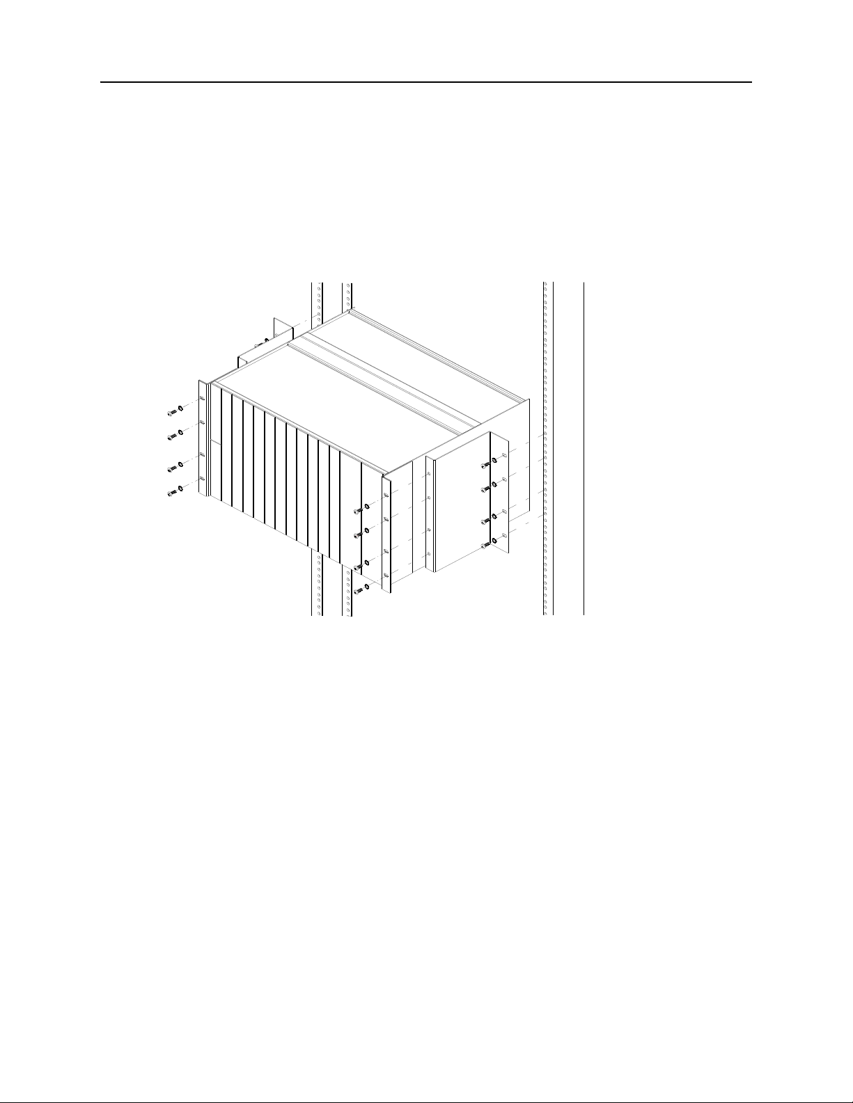
19” EIA Flush Rack Mounting
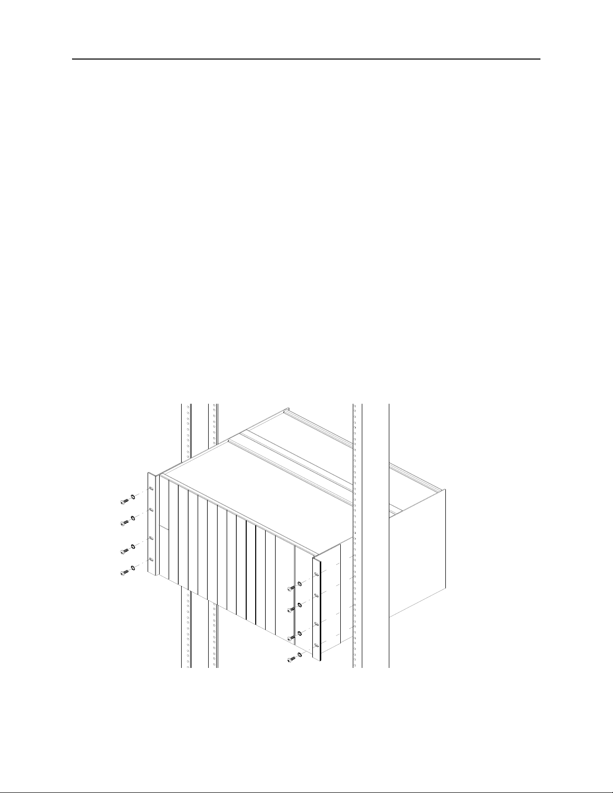
Incorporated into the design of the DNX-11 chassis are mounting brackets which allow the DNX
to be mounted to a standard E.I.A. 19-inch equipment rack.
1. Line up the mounting brackets on the DNX-11 unit with the 19-inch equipment rack.
2. Slide the DNX-11 unit into the equipment rack. Refer to Figure 1 below.
Figure 1: DNX-11 Rack Mounting (19-inch rack).
3. Secure the DNX-11 unit in place using thread-forming screws.
Make sure you leave enough space above the DNX unit for the N+1 Protection Switch to resid e,
approximately 3U high.
DOC-001-11001 (Rev. 006) 3 DNX Quick Install & Setup Guide
Page 12
DNX-11 Installation Rack Mounting
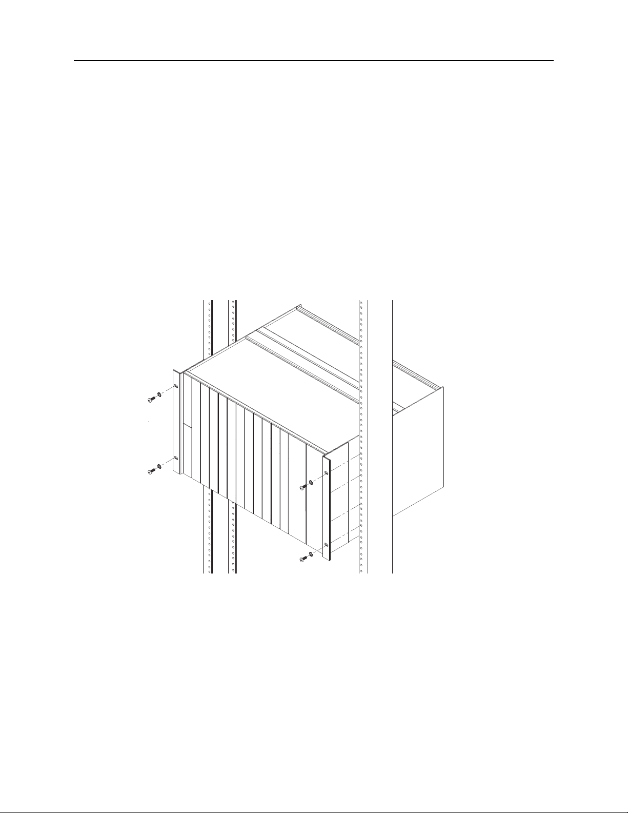
23” EIA Flush Rack Mounting
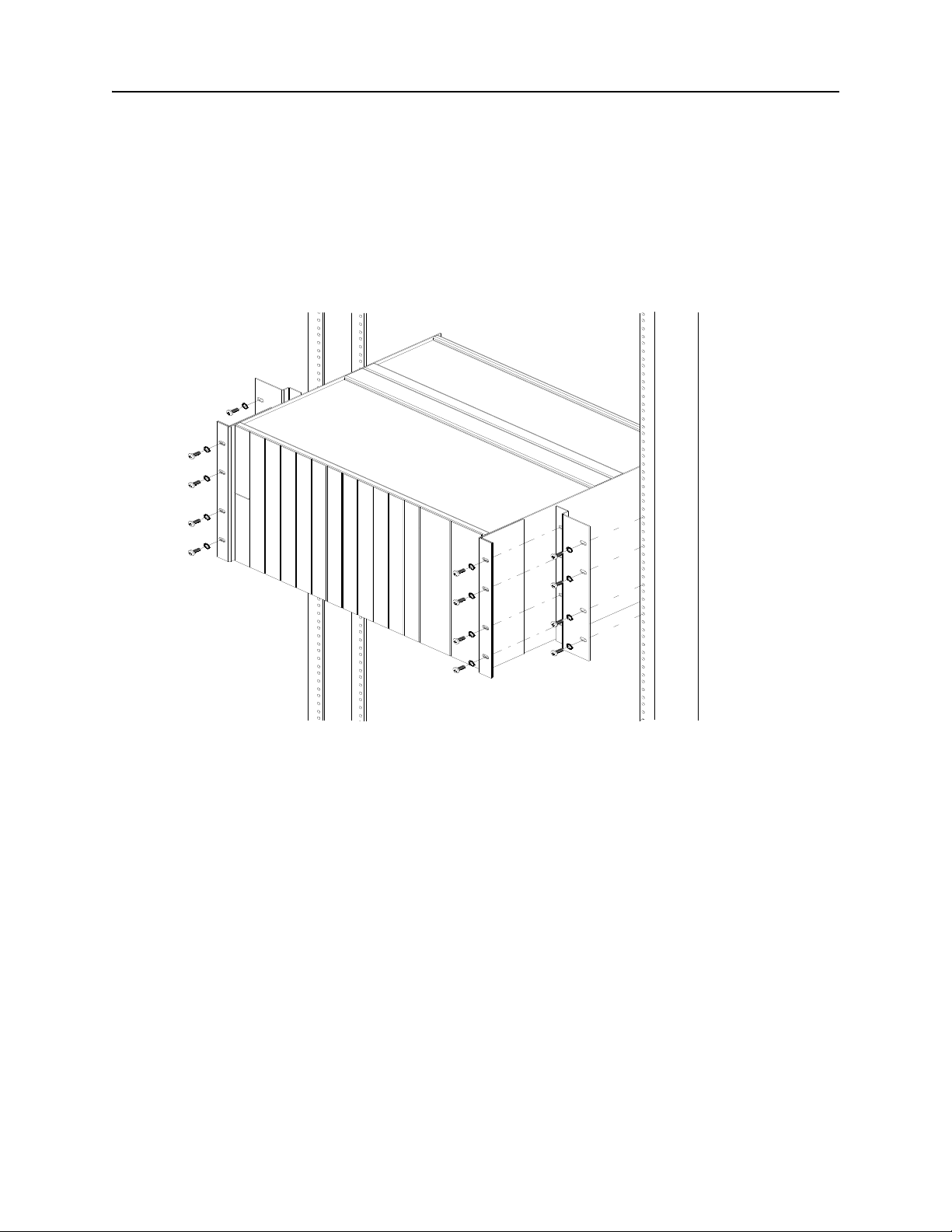
1. Orient the flush mounting brackets behind the DNX-11 mounting brackets as shown in
figure 2. Align the four small threaded holes of the flush mounting brackets with the DNX11 mounting brackets.
Figure 2: DNX-11 Rack Mounting (23-inch rack).
2. Secure the DNX-11 unit to the flush mounting brackets using #10-32 thread-forming
screws.
3. Slide the DNX-11 unit into the equipment rack.
4. Line up the oval holes of the flush mounting brackets with the 23-inch equipment rack.
5. Secure the DNX-11 unit in place using appropriate thread-forming screws.
Make sure you leave enough space above the DNX unit for the N+1 Protection Switch to resid e,
approximately 3U high.
DOC-001-11001 (Rev. 006) 4 DNX Quick Install & Setup Guide
Page 13
DNX-11 Installation Rack Mounting
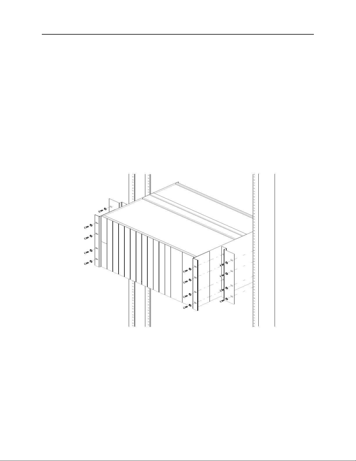
23” EIA Center Rack Mounting
1. Orient the center mounting brackets behind the DNX-11 mounting brackets as shown in
figure 3. Align the four small threaded holes of the center mounting brackets with the DNX11 mounting brackets.
Figure 3: DNX-11 Center Rack Mounting.
2. Secure the DNX-11 unit to the center mounting brackets using thread-forming screws.
3. Slide the DNX-11 unit into the equipment rack.
4. Line up the oval holes of the center mounting brackets with the 23-inch e quipment rack.
5. Secure the DNX-11 unit in place using #10-32 thread-forming screws. The center, not the
front, will be resting on the equipment rack.
Make sure you leave enough space above the DNX unit for the N+1 Protection Switch to resid e,
approximately 3U high.
DOC-001-11001 (Rev. 006) 5 DNX Quick Install & Setup Guide
Page 14
DNX-11 Installation Rack Mounting
19” Telco Flush Rack Mounting
Adapts a standard 19” flush EIA rack moun t configuration for center mounting within a 1 9” wide
Telco equipment rack or cabinet via provided bracket set.
Note: If you intend to install an N+1 Protection Switch, make sure that you leave enough
space above the DNX-11 for the N+1 Protection Switch to reside - approximately 3U
high.
1. Line up the mounting brackets on the DNX-11 unit with the 19-inch equipment rack.
2. Slide the DNX-11 unit into the equipment rack. Refer to the figure below.
Figure 4: DNX-11 Telco Flush Rack Mounting (19-inch rack)
3. Secure the DNX-11 unit in place using #12-24 thread-forming screws.
DOC-001-11001 (Rev. 006) 6 DNX Quick Install & Setup Guide
Page 15
DNX-11 Installation Rack Mounting
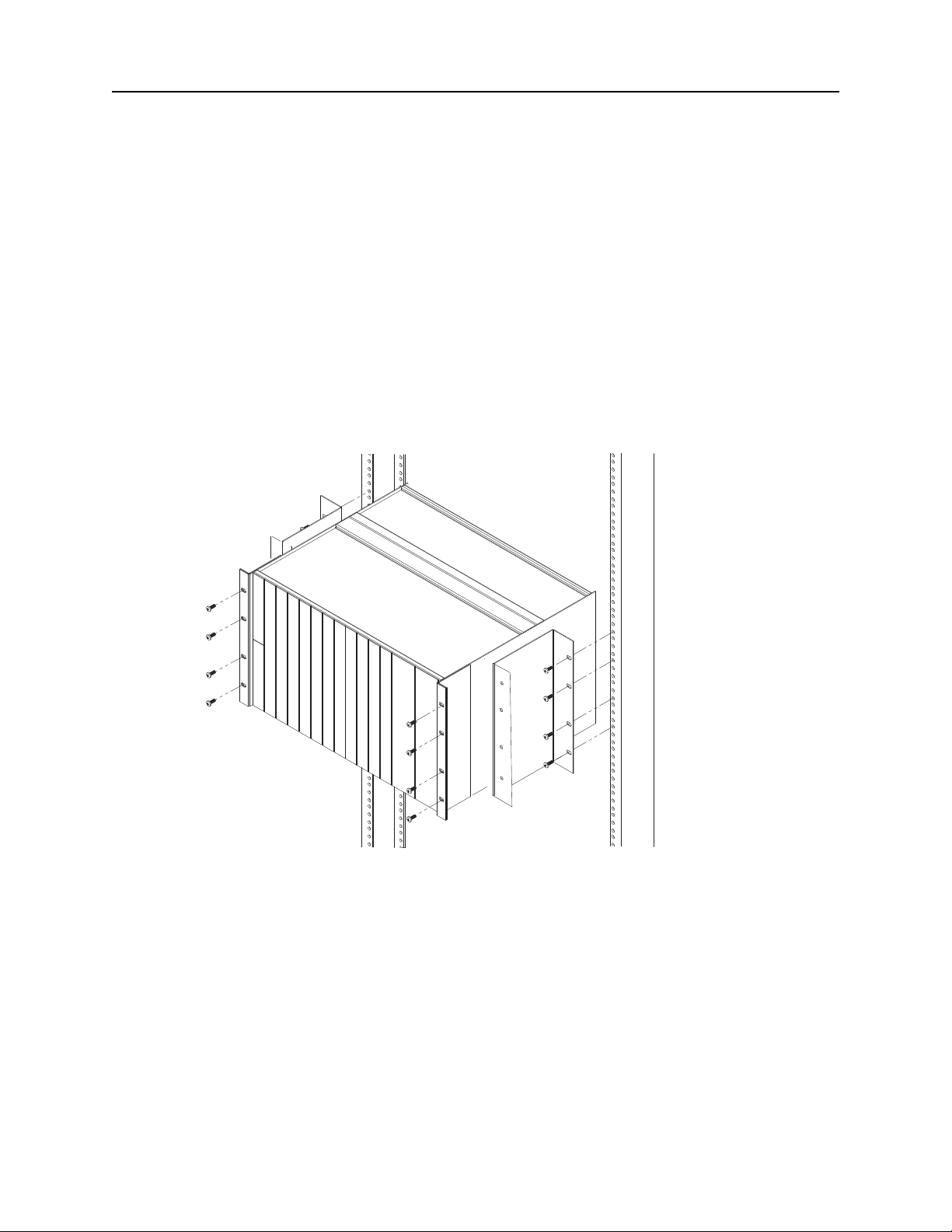
23” Telco Flush Rack Mounting
Adapts a standard 19” flush EIA rack mount configuration for flush mounting within a 23” wide
Telco equipment rack or cabinet via provided bracket set.
Note: If you intend to install an N+1 Protection Switch, make sure that you leave enough
space above the DNX-11 for the N+1 Protection Switch to reside - approximately 3U
high.
1. Orient the flush mounting brackets behind the DNX-11 mounting brackets as shown in
Figure 5. Align the four small threaded holes of the flush mounting brackets with the DNX11 mounting brackets.
Figure 5: DNX-11 Telco Flush Rack Mounting (23-inch rack).
2. Secure the DNX-11 unit to the flush mounting brackets using thread-f or ming sc re ws.
3. Slide the DNX-11 unit into the equipment rack.
4. Line up the oval holes of the flush mounting brackets with the 23-inch equipment rack.
5. Secure the DNX-11 unit in place using #12-24 thread-forming screws.
DOC-001-11001 (Rev. 006) 7 DNX Quick Install & Setup Guide
Page 16
DNX-11 Installation Rack Mounting
23” Telco Center Rack Mounting
Adapts a standard 19” flush EIA rack moun t configuration for center mounting within a 2 3” wide
Telco equipment rack or cabinet via provided bracket set.
Note: If you intend to install an N+1 Protection Switch, make sure that you leave enough
space above the DNX-11 for the N+1 Protection Switch to reside - approximately 3U
high.
1. Orient the center mounting brackets behind the DNX-11 mounting brackets as shown in
Figure 6. Align the four small threaded holes of the center mounting bracket s with the DNX11 mounting brackets.
Figure 6: DNX-11 Telco Center Rack Mounting (23-inch rack).
2. Secure the DNX-11 unit to the center mounting brackets using thread-forming screws.
3. Slide the DNX-11 unit into the equipment rack.
4. Line up the oval holes of the center mounting brackets with the 23-inch equipment rack.
5. Secure the DNX-11 unit in place using #12-24 thread-forming screws. The center, not the
front, will be resting on the equipment rack.
DOC-001-11001 (Rev. 006) 8 DNX Quick Install & Setup Guide
Page 17
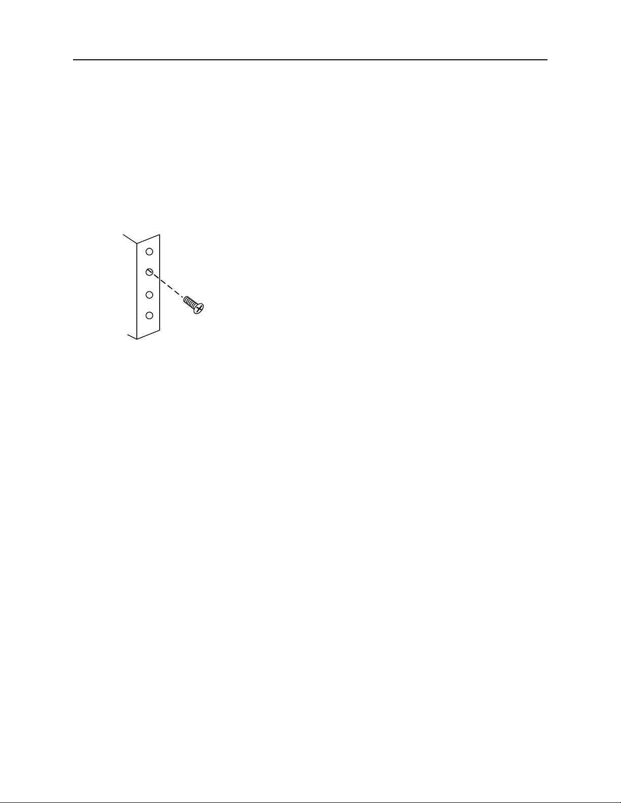
DNX-11 Installation Proper Grounding
Mounting
Bracket
Rack Mounting
Screw
Proper Grounding
Grounding via Rack Mount
1. Mount the DNX to the equipment rack using rack-mounting screws as shown in Figure 7
below:
Figure 7: Properly Grounding the DNX.
DOC-001-11001 (Rev. 006) 9 DNX Quick Install & Setup Guide
Page 18
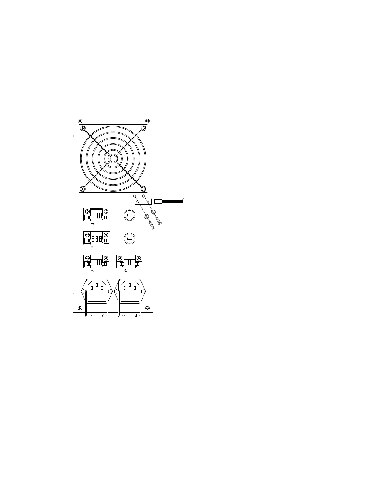
DNX-11 Installation Proper Grounding
++
++--
--
++--
++--
TALK BATTERY
TALK BATTERY
SIGNAL BATTERY
SIGNAL BATTERY
DC POWER SLOT #2
DC POWER SLOT #1
AC POWER SLOT #2
AC POWER SLOT #1
#10-32
Screws
External-Toothed
Lockwashers
Grounding Strap
Grounding via Grounding Strap
Using two #10-32 screws and external-toothed lockwashers (provided), connect a grounding
strap lug to the grounding points near the power terminal block as shown in Figure 8.
Figure 8: Grounding Strap Conn ection.
DOC-001-11001 (Rev. 006) 10 DNX Quick Install & Setup Guide
Page 19

DNX-11 Installation Installing DNX-11 Power Supply Module(s)
Installing DNX-11 Power Supply Module(s)
The new power supplies have thumbscrews that secure them to the DNX Chassis. The older
power supply modules were secured to the chassis with Phillips Head screws. Care must be
taken when removing the screws from th e olde r po wer supplie s to prevent stripping. Use a No.
1 Phillips Head screwdriver and apply firm, even pressure. Should you strip the screws, do not
pry them from the chassis. Contact the Sycamore Networks Technical Assistance Center
(TAC) at 1-877-526-2321 for assistance.
1. Remove the power module from the anti-static bag.
2. Hold the power supply module upright and slide it into the far right slot in the DNX chassis,
following the white card guide.
3. When the power supply module is properly aligned, fasten the screws into the module.
Note: The power source that you will be using to provide power to the DNX dictates that you
use the matching power supply. For connection to DC power, use the DC power supply
module (part number MKT-006-11048). For connection to AC power, use the AC
power supply module (part number MKT-006-11206).
Internal Fuse/Wattage Requirements
DNX-11: Redundant or Non-Redundant Module is 90-230VAC (47-63Hz), or -48VDC, 200
watts.
Table 1: Internal Equipment Fuses.
DC Power Modules
(DNX-1 1)
AC Power Connector
(DNX-1 1)
FUS-003-10000
10 Amp, 250V
FUS-003-05000
5 Amp, 250V
DOC-001-11001 (Rev. 006) 11 DNX Quick Install & Setup Guide
Page 20
DNX-11 Installation DNX-11 AC Power
++-- ++--
DC POWER SLOT #2
DC POWER SLOT #1
AC POWER SLOT #2
AC POWER SLOT #1
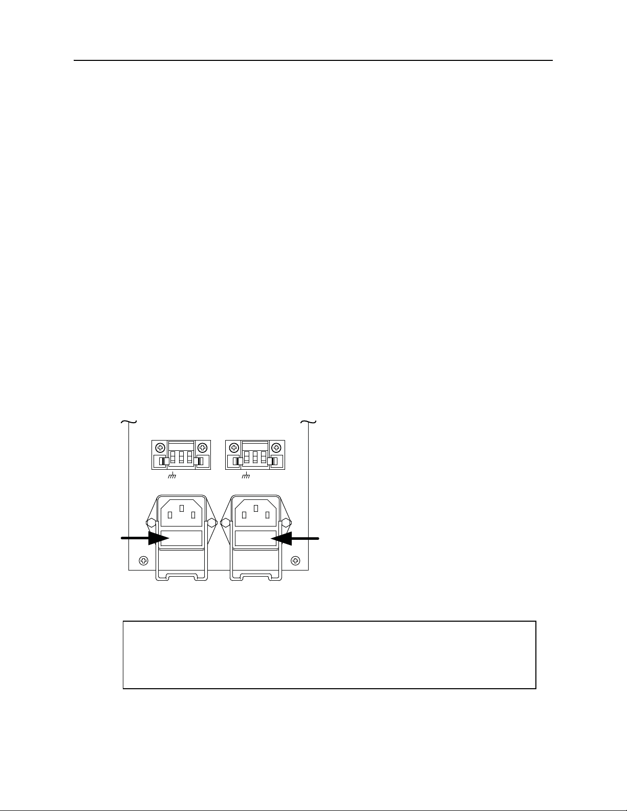
Fuse Locations
( Pry off cover )
DNX-11 AC Power
The AC-powered version of the DNX-11 contains two integrated 110/220VAC (auto-sensing)
power supplies (part number MKT-006-11206). To take advantage of the redundant power
supplies, the DNX-11 requires two 110VAC or 220VAC power connections.
AC Power Requirements
The AC model of the DNX-11 will automatically sense whether it is connected to 110VAC or
220VAC power, and adjust accordingly. Requirements for the power connection are as follows:
• 110VAC or 220VAC power, at a maximum of 3 amps, 300 watts.
• Use the AC power cord that is supplied with the unit.
• The DNX-11 shall be installed in accordance with 110-16, 110-17, and 110-18 of the
National Electrical Code, ANSI/NFPA No. 70.
AC Power Fuses
The power receptacles on this model contain a 2A, 250V Fast-Acting fuse and a spare. To
access the fuse, use a small screwdriver to pry off the rectangular panel located at the to p of
the AC receptacle (see Figure 9).
Figure 9: AC Power Fuse Locations.
Power must be disconnected before attempting to remove/replace fuses.
For continued protection against risk of fire, replace the fuse only with a fuse
of the same type and rating: 2A, 250V, Fast-Acting.
WARNING
DOC-001-11001 (Rev. 006) 12 DNX Quick Install & Setup Guide
Page 21
DNX-11 Installation DNX-11 AC Power
++
++--
--
++--
++--
TALK BATTERY
TALK BATTERY
SIGNAL BATTERY
SIGNAL BATTERY
DC POWER SLOT #2
DC POWER SLOT #1
AC POWER SLOT #2
AC POWER SLOT #1
Connecting AC Power to a DNX-11
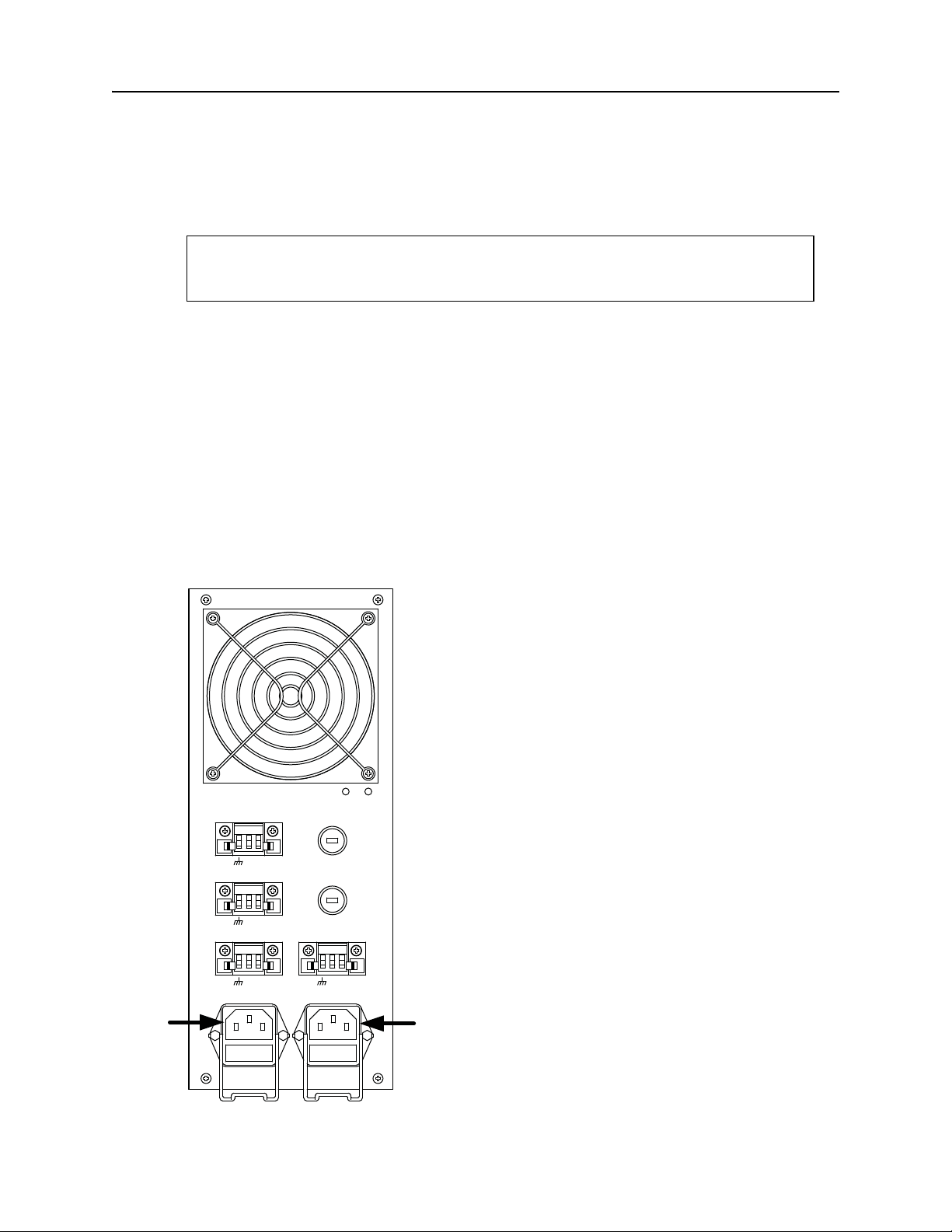
An AC power supply requires an AC power cord with a three-prong grounded plug. This plug
must be inserted into the three prong grounded receptacle (shown in Figure 10).
Caution
Do not use an adapter to connect the AC power cord to an ung rounded recept acle.
1. Install the AC Power Supply Module as detailed in the previous procedure.
2. Insert the AC power cord plug into the corresponding three-prong receptacle on the rear
panel.
3. Repeat steps 1-4 for the second power supply module. If a second power supply is not
used, cover the empty slot with a blank panel.
4. Apply power to the unit by connecting the power cord to a 110 volt or 220 volt AC power
source.
5. An LED on the power supply will illuminate if properly installed and AC power is On. The
DNX-11 unit will also begin its power-up sequence.
Figure 10: DNX-11 AC Power Connection.
DOC-001-11001 (Rev. 006) 13 DNX Quick Install & Setup Guide
Page 22

DNX-11 Installation DNX-11 DC Power
DNX-11 DC Power
The DC-powered version of the DNX-11 contains two integrated -48VDC power supplies (part
number MKT-006-11048). To take advantage of the redundant power supplies, the DNX-11
requires two -48 volt DC power connections.
DC Power Requirements
The DNX-11 is designed to operate on -48 volt DC power, at a maximum of 3 amps, 200 watts.
Requirements for the actual power connection are as follows:
• The supply wiring should be 12 to 16 AWG.
• The -48VDC supply should be electrically isolated from any AC source.
• The -48VDC source should be reliably connected to earth ground.
• The DNX-11 shall be installed in accordance with 110-16, 110-17, and 110-18 of the
National Electrical Code, ANSI/NFPA No. 70.
DC Power Fuses
The power supply on this DNX-11 model contains an integral 10A, 250V Fast-Acting fuse.
DOC-001-11001 (Rev. 006) 14 DNX Quick Install & Setup Guide
Page 23
DNX-11 Installation DNX-11 DC Power
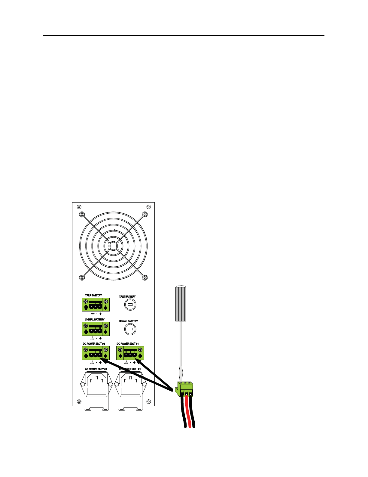
Connecting DC Power (-48VDC) to a DNX-11
Note: When powering the DNX-1 1 from a DC power sour ce, use two sep arate fuse p anels or
a fuse panel with redundant (A and B) fuse positions.
1. Mount the unit in a rack as specified previously.
2. Shut off power to the DC supply leads.
3. Strip the insulation back approximately 5/16 inch (8mm) from the end of each lead.
4. Note the positions of earth, negative and positive on the DC power plug (designations are
on the DNX-11 chassis).
5. Remove the DC power plug from the mating receptacle on the DNX rear panel.
6. Insert the “earth” lead into the earth terminal clamp on the power terminal block and tighten
the clamp screw using a small flat screwdriver (see Figure 11).
Figure 11: Co nnecting the DNX-11 to DC Power.
DOC-001-11001 (Rev. 006) 15 DNX Quick Install & Setup Guide
Page 24

DNX-11 Installation DNX-11 DC Power
7. Insert the “-48 volt supply” wire into the negative terminal and tighten the clamp screw.
8. Insert the “return” wire into the positive terminal and tighten the clamp screw.
9. Insert the power terminal block into the mating receptacle on the rear panel.
10. Repeat steps 1-9 for the second power supply connection. If a second power supply is not
used, cover the empty slot with a blank panel.
1 1. Apply power to the unit. The LEDs on the front panel will flash as the unit powers up, loads
software, and runs a self-test. This will take approximately two minutes.
12. To minimize disturbance to the wires through casual contact, secure the cables to the rack
frame using multiple cable ties. The first tie should be within 6 inches of the terminal block.
DOC-001-11001 (Rev. 006) 16 DNX Quick Install & Setup Guide
Page 25
DNX-11 Installation DNX-11 DC Power
Connecting the Talk Battery or Signal Battery
This connection is used exclusively for voice applications. The Signal Battery input is provided
for applications where separate talk and signal power is required.
1. Shut off power to the Talk Battery or Signal Battery leads.
2. Strip the insulation back approximately 5/16 inch (8mm) from the end of each lead.
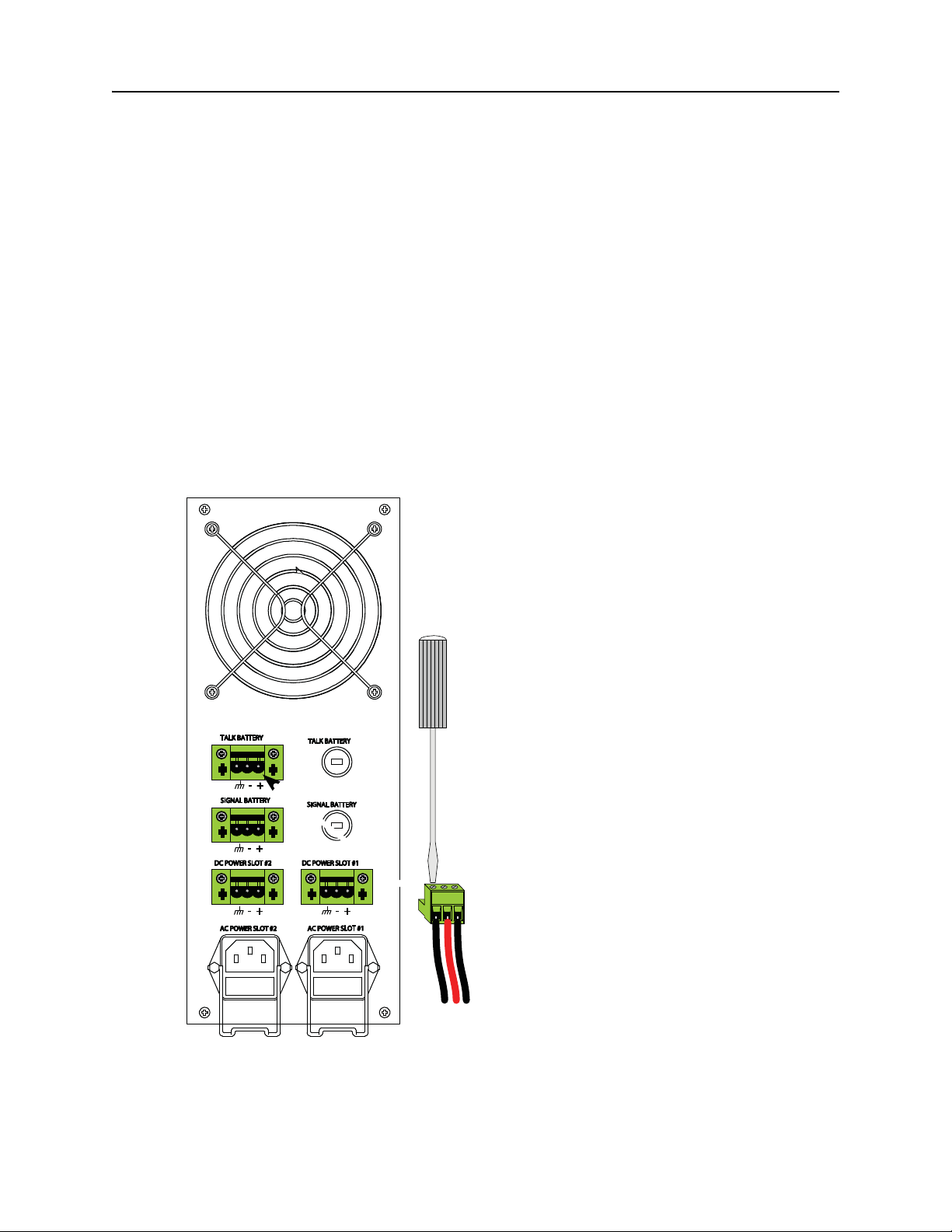
3. Note the positions of earth, negative and positive on the talk battery or signal battery power
receptacle.
4. Remove the talk battery or signal battery power plug from the mating recept acle on the rear
panel.
5. Insert the “earth” lead into the earth terminal clamp on the power terminal block and tighten
the clamp screw using a small flat screwdriver (see Figure 12).
Figure 12: Connecting the Talk Battery.
DOC-001-11001 (Rev. 006) 17 DNX Quick Install & Setup Guide
Page 26
DNX-11 Installation DNX-11 DC Power
DNX Talk Battery
-48VDC (-)
DC Re turn (+)
TELCO
Ground
6. Insert the “-48VDC” lead into the negative terminal clamp and tighten the clamp screw.
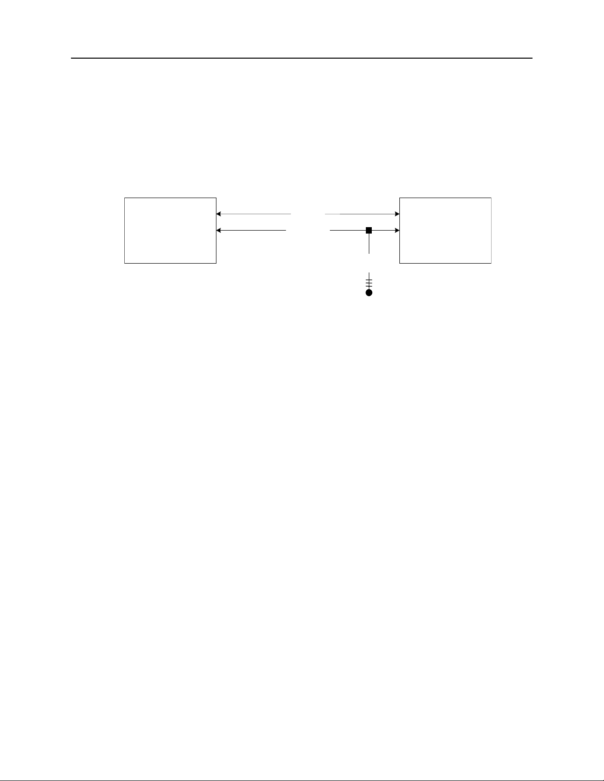
7. Insert the “return” lead into the negative terminal clamp and tighten the clamp screw. For a
talk battery connection, DC Return should be tied to the service provider for the FXO/FXS
Ground Start operations to work properly. See Figure 13.
Figure 13: Talk Battery Connections.
8. Insert the power terminal block into the mating receptacle on the rear panel.
9. To minimize disturbance to the wires through casual contact, secure the cables to the rack
frame using multiple cable ties. The first tie should be within 6 inches of the terminal block.
10. Talk Battery or Signal Battery power may now be applied to the unit.
DOC-001-11001 (Rev. 006) 18 DNX Quick Install & Setup Guide
Page 27
DNX-11 Installation DNX-11 DC Power
+
-
-
-
-
Talk Battery & Signal Battery Fuses
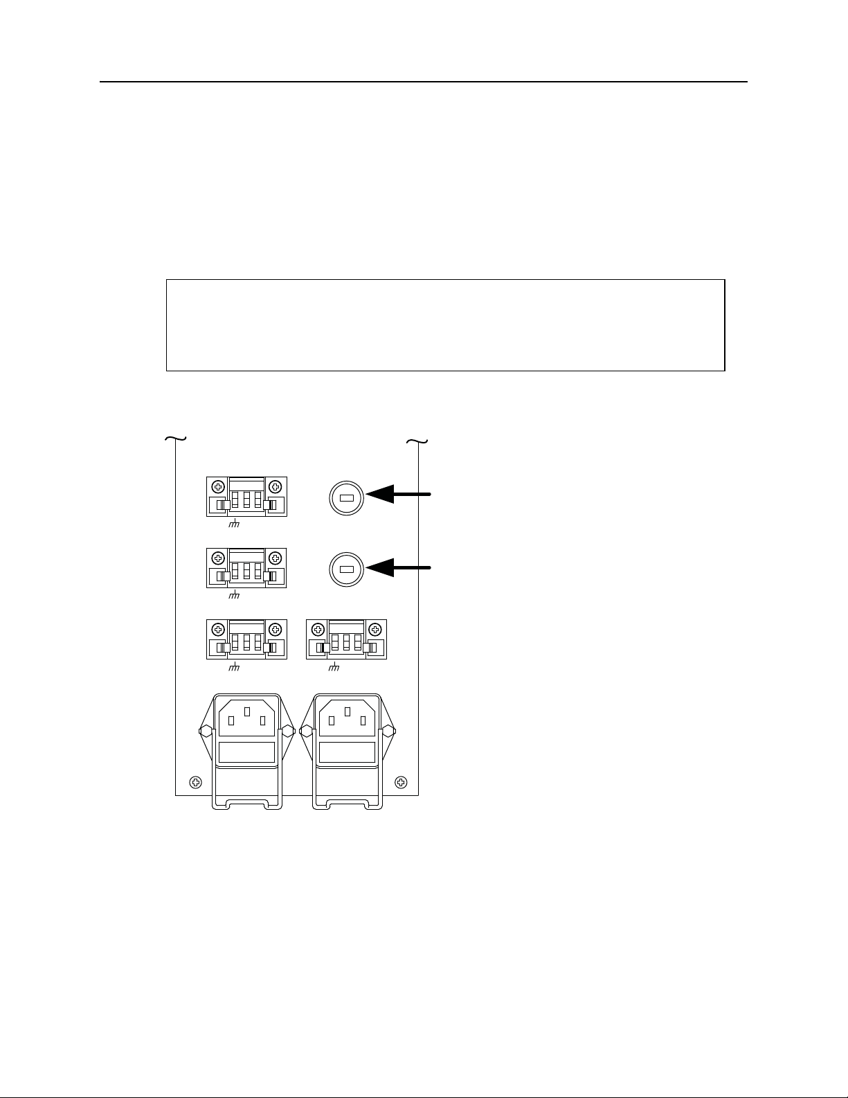
The talk battery and signal battery fuses on this model are both 2A, 250V Delayed Action (SloBlo) fuses. To access the fuses, use a small screwdriver and unscrew the cover 1/4 turn
counter-clockwise. The cover should pop out, and the fuse can then be removed (see Figure
14).
WARNING
Power must be disconnected before attempting to remove/replace fuses.
For continued protection against risk of fire, replace the fuse only with a fuse
of the same type and rating: 2A, 250V, Delayed Action (Slo-Blo).
Figure 14: Talk Battery & Signal Battery Fuse Locations.
TALK BATTERY
++-
SIGNAL BATTERY
+
-
DC POWER SLOT #2
++-
AC POWER SLOT #2
TALK BATTERY
SIGNAL BATTERY
DC POWER SLOT #1
++-
AC POWER SLOT #1
Fuse Locations
(Unscre w ¼ Turn)
DOC-001-11001 (Rev. 006) 19 DNX Quick Install & Setup Guide
Page 28
DNX-11 Installation Installing the System Manager Controller
System
Manager II
READY
LAN
CRITL
MAJOR
MINOR
ACO
Manager
Interface
Station
Clock
X.25
Protect
Swt
A1
A2
B1
B2
Phone Line
Terminal
10 Base T
NC
NO
C
NO
NC
C
NO
NC
C
1
3
2
Alarm
SMC IIA
Mgr I/F
Station Clk
CC
PSX
A1
A2
B1
B2
Phone Line
Terminal
10/100
NC
NO
C
NO
NC
C
NO
NC
C
1
3
2
Alarm
T1/E1
C1
C2
D1
D2
Installing the System Manager Controller
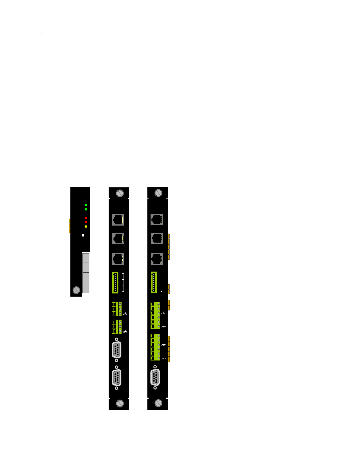
To install an SMC II module into a DNX-11 chassis:
1. Remove the SMC II module and corresponding SMC II rear interface module from the antistatic bags.
2. Hold the front SMC II module upright (vertically) and slide it into a slot (far left) in the DNX1 1 chassis following the white card guide. It does not matter if you insert the card in th e top
or bottom slot.
3. Next, hold the full-size SMC II or SMC IIA rear interface module upright and slide it into the
rear of the DNX-1 1 chassis following the white card guide (far right). Make sure it is aligned
with the front SMC II module.
4. When both cards are aligned and inserted properly, fasten the thumb screws securely in
both front and rear cards. If done properly, the DNX will reset.
Figure 15: SMC II front and SMC II & SMC IIA rear interface module set.
DOC-001-11001 (Rev. 006) 20 DNX Quick Install & Setup Guide
Page 29
DNX-11 Installation SMC II Module Jumper Configuration
MC68EN360MC68EN360
10.000 MHZ10.000 MHZ
DS1287DS1287
16.384 MHZ16.384 MHZ
DS26C31DS26C31
QS3244S0QS3244S0
DS90C032DS90C032
XC4020XLAXC4020XLA
4.7K4.7K4.7K4.7K
74LS12574LS125
4.7K4.7K
AM29LV008BTAM29LV008BT
TC59S6416BFTTC59S6416BFT
1624ADL1624ADL
DS1232DS1232
29F04029F040
XC9572-10XC9572-10
-120BEC-120BEC
-120BEC-120BEC
AM29LV008BTAM29LV008BT
-10-10
-10-10
TC59S6416BFTTC59S6416BFT
33.00033.000
MHZMHZ
25nSEC25nSEC
DELAY LINEDELAY LINE
SN74LVTHSN74LVTH
1624ADL1624ADL
SN74LVTHSN74LVTH
1624ADL1624ADL
SN74LVTHSN74LVTH
1624ADL1624ADL
SN74LVTHSN74LVTH
20.00020.000
MHZMHZ
C46C46
C45C45
U19U19
XU18XU18
Front System Mgr IIFront System Mgr II
R18R18
U3U3
R17R17
C104C104
C65C65
R1R1
R2R2
RN1RN1
D1D1
A1A1
R5R5
R6R6
DS2DS2
DS1DS1
C1C1
Q1Q1
FB1FB1
C8C8
J2J2
R39R39
R40R40
U1U1
D12D12
D1D1
J1J1
D6D6
A6A6
F1F1
R15R15
U5U5
C10C10
C106C106
R9R9
R11R11
R12R12
U4U4
C6C6
R10R10
R16R16
R61R61
R3R3
C2C2
R4R4
C3C3
R7R7
R8R8
C4C4
Q2Q2
C5C5
C7C7
U2U2
R26R26
Component SideComponent Side
C29C29
CR1CR1
U9U9
R56R56
U10U10
C30C30
C27C27
R28R28
DS3DS3
CR2CR2
U11U11
DS4DS4
C32C32
C41C41
C40C40
C31C31
R29R29
C34C34
C33C33
U14U14
C38C38
C39C39
U7U7
R21R21
C14C14
C13C13
RN3RN3
U6U6
R20R20
R19R19
RN2RN2
C17C17
C28C28
C103C103
R23R23
C26C26
C16C16
L1L1
U8U8
R25R25
U12U12
ASM:ASM:
R27R27
C98C98
U13U13
C43C43
C36C36
U16U16
C37C37
C44C44
C35C35
REV:REV:
U15U15
C99C99
C42C42
U18U18
C51C51
C50C50
C58C58
C57C57
U22U22
C55C55
C56C56
WDWD
U29U29
11
FCFC
DBDB
C59C59
R36R36
U26U26
U27U27
C48C48
R57R57
U21U21
C49C49
U23U23
C53C53
C54C54
J5J5
BDMBDM
J4J4
R35R35
R34R34
PCB-006-02352PCB-006-02352
C47C47
XU25XU25
R60R60
U25U25
C52C52
R33R33
R32R32
DS8DS8
R31R31
R30R30
MT3MT3
Rev 1Rev 1
11
S1S1
DS9DS9
DS7DS7
DS6DS6
DS5DS5
R68R68
R69R69
R70R70
C9C9
R73R73
R71R71
R72R72
C60C60
J5J5
Revision LabelRevision Label
SMC II Module Jumper Configuration
On the SMC II front module, there is a jumper block that is used to select whether the SMC is
installed in a standalone DNX-11 nest, or in a subordinate nest (Nest 2 through 8) of a DNX-88.
Jumper block location and designator are de pendent on the hardware re vision level of the SMC
II Module. The hardware revision level can be determined from the labeling on the printed circuit board or a label on the shipping container.
Note: Refer to the DNX-88 Reference and User’s Guide for specific information on the DNX-
88 Multiservice Cross-Connect.
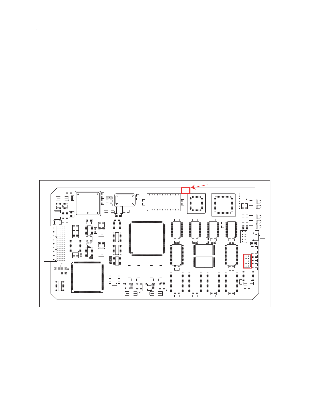
Revision 0 and Revision 1 SMC II Modules
For Revision 0 and Revision 1 SMC II printed circuit boards, the revision label is located as
shown in Figure 16. The jumper block is labeled J5, and its location is also shown in Figure 16.
See Figure 17 for jumper shunt placement for DNX-11/-4 or DNX-88 use.
Figure 16: SMC II, Hardware Revision 0 and 1 - Revision Label and J5 Jumper Block Locations.
DOC-001-11001 (Rev. 006) 21 DNX Quick Install & Setup Guide
Page 30
DNX-11 Installation SMC II Module Jumper Configuration
J5
4
6
8
10
2
Spare Shunt
(Not Required)
DNX-11/4 (Standalone Nest) DNX-88 (Nests 2 through 8)
9
1
7
5
3
Required
Shunt
DB
FC
WD
J5
4
6
8
2
1
7
5
3
DB
FC
WD
10
9
Revision 0 and Revision 1 SMC II Modules - Jumper Placement
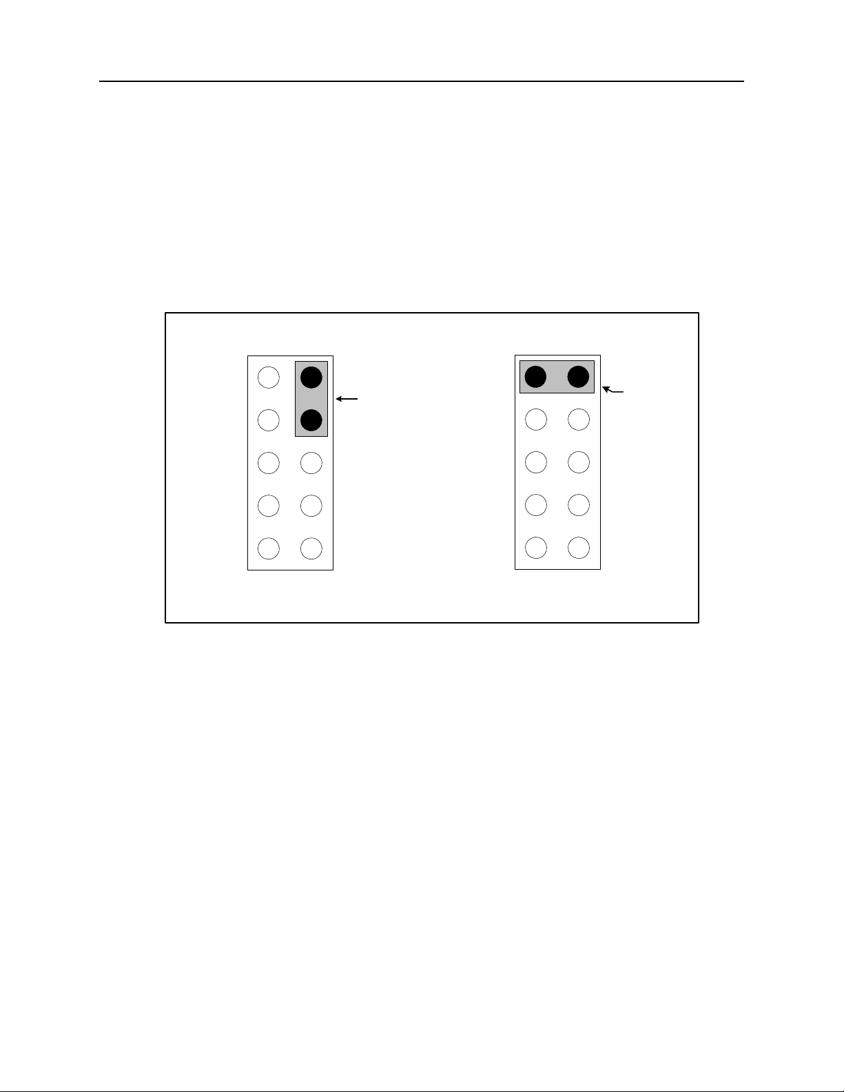
For DNX-11/-4 standalone applications, a jumper is not necessary, however, SMC II modules
are shipped with a spare jumper shunt across inactive pins (such as pins 7 and 9) in order to
facilitate later DNX-88 application upgrades if desired. For DNX-88 applications (Nests 2
through 8), the jumper shunt should be placed across pins 9 and 10 of jumper block J5. Refer
to Figure 17 for placement.
Figure 17: Revision 0 and Revision 1 SMC II Module - Jumper Shunt Placement.
DOC-001-11001 (Rev. 006) 22 DNX Quick Install & Setup Guide
Page 31
DNX-11 Installation SMC II Module Jumper Configuration
J3
Revision Label
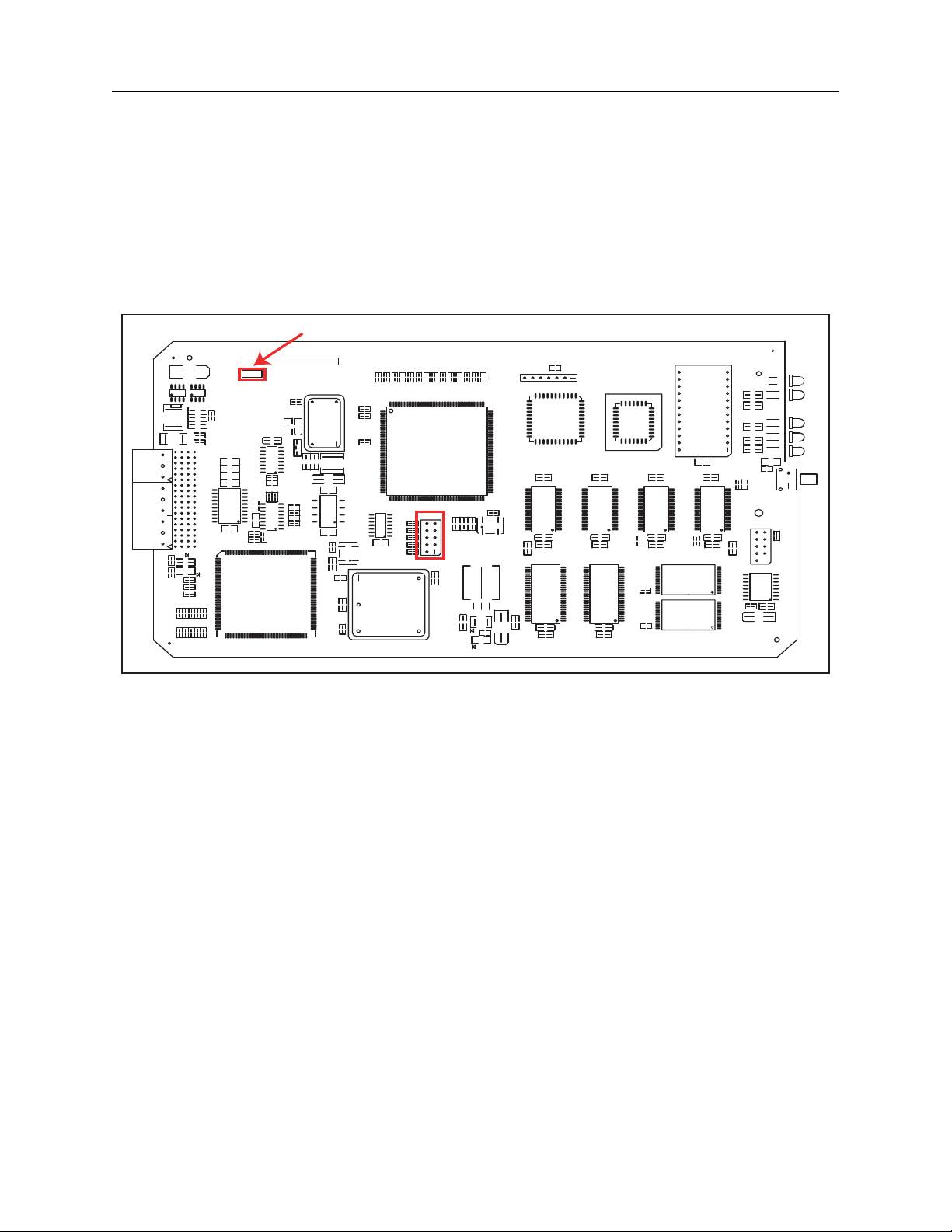
Revision 2 SMC II Modules
For Revision 2 SMC II printed circuit boards, the revision label is located as shown in Figure .
The jumper block is labeled
jumper shunt placement for DNX-11 or DNX-88 use.
Figure 18: SMC II, Hardware Revision 2 - Revision Label and J3 Jumper Block Location.
J3, and its location is also shown in Figure 18. See Figure 19 for
Revision Label
MT14 MT40
C1
ASM:
REV:
C2
F1
A6
A1
R7
R8
R9
R3
R5
R6
R4
Front System Mgr II
Q2
PCB-006-02352
Rev 2
R14
Component Side
R19
C3
R15
R16
D6
R20
J1
R21
R22
D1
R23
D12
U1
J2
QS3244S0
C4
D1
DS1
DS2
R17
R12
R10
R11
R13
R18
C8
U3
C6
R24
R25
XC4020XLA
R26
C5
R30
C9
DS26C31
R27
R28
R29
DS90C032
R34
U4
C7
U2
U6
C10
16.384
MHZ
L1
R36
R35
TP1
R31
R32
25nSEC
R33
DELAY LINE
U5
R37
TP2
TP4
TP5
TP3
Q1
FB1
R1
R2
MT16
C11
C15
C12
C13
20.000
MHZ
C14
R38
C16
R39
R43
R44
R46
R45
R47
R48
R54
R55
TP9
R49
R50
74LS125
R51
R52
R53
TP10
MC68EN360
TP11
J3
J3
J3
1
R40
R41
R42
TP8
TP6
U9
U7
C17
TP7
U8
10,000 MHZ
R61
R56
R58
R57
R59
R60
TP13
U10
TP23
TP18
TP14
TP20
TP12
TP16
TP15
FC
C19
DB
WD
C18
U11
C20
R63
TP19
TP17
33.000
MHZ
L2
U12
C21
TP21
C22
CR1
R62
DS3
TP25TP22
TP24
C23
XC9572-10
C25
C24
SN74LVTH
U14
R64
J4
1
J4
U15
U16
U13
1624ADL
C26
C27
-10
TC59S6416BFT
C28
C29
29F040
C30
U19
1624ADL
SN74LVTH
C31 C36
C32
U17
-10
TC59S6416BFT
C34
C33
XU18
R65
R66
R67
U18
SN74LVTH
U21
TP26
TP27
C38
C35
1624ADL
C37
U20
AM29LV008BT
-120BEC
AM29LV008BT
-120BEC
U23
DS1287
U22
R68
C39
1624ADL
SN74LVTH
C41
MT15
DS4
MT3
R72
DS5
R73
DS6
R74
DS7
R75
R76
DS8
C45
R77
R69
R70
S1
MT2
BDM
J5
C40
R78
J5
C42
1
U24
TP28
DS1232
R71
C43
TP29
C44
MT1
DOC-001-11001 (Rev. 006)
23 DNX Quick Install & Setup Guide
Page 32
DNX-11 Installation SMC II Module Jumper Configuration
J3
4
6
8
10
2
Spare Shunt
(Not Required)
DNX-11/4 (Standalone Nest) DNX-88 (Nests 2 through 8)
9
1
7
5
3
Required
Shunt
DB
FC
WD
J3
4
6
8
2
1
7
5
3
DB
FC
WD
10
9
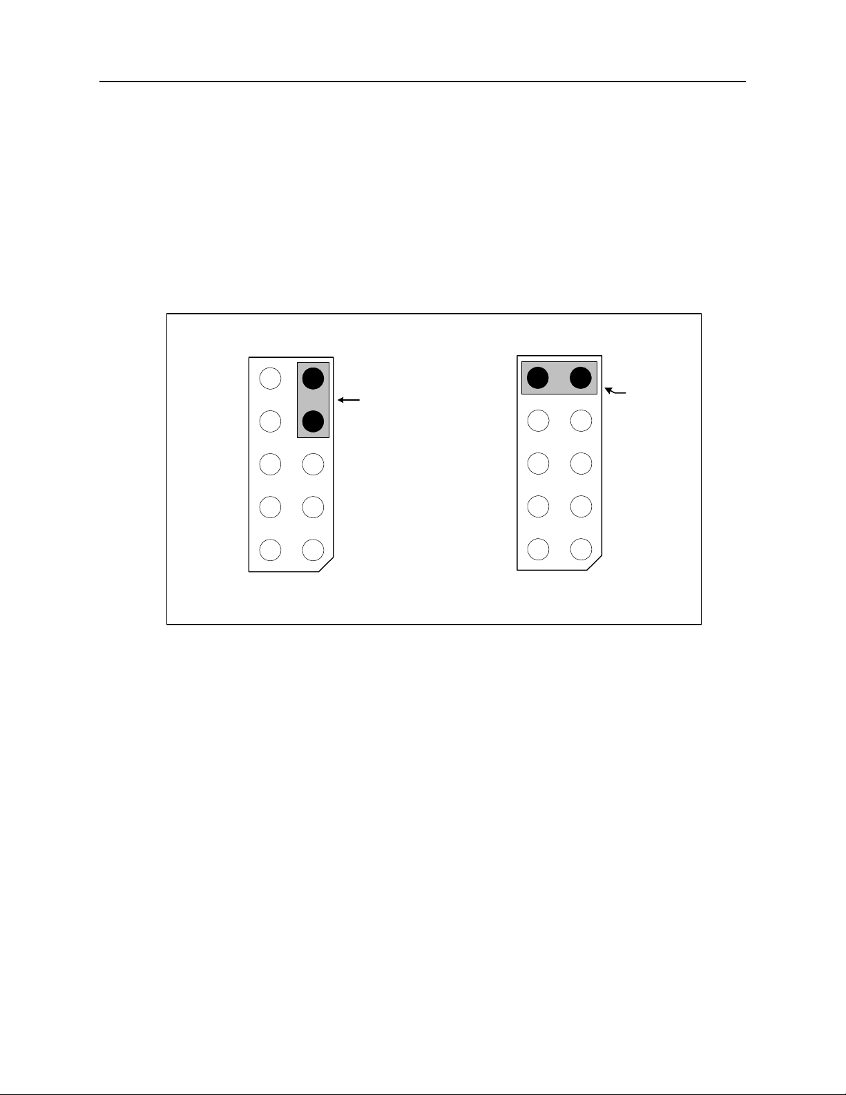
Revision 2 SMC II Modules - Jumper Placement
For DNX-11/-4 standalone applications, a jumper is not necessary, however, SMC II modules
are shipped with a spare jumper shunt across inactive pins (such as pins 7 and 9) in order to
facilitate later DNX-88 application upgrades if desired. For DNX-88 applications (Nests 2
through 8), the jumper shunt should be placed across pins 9 and 10 of jumper block
to Figure 19 for placement.
Figure 19: Revision 2 SMC II Module - Jumper Shunt Placement.
J3. Refer
The SMC II card is designed to be used in the DNX-11 and the DNX-88 expansion node. A
jumper on the SMC II front card is used to set up the DNX for either use, since the SMC II reacts
differently depending upon it s environment. The position of the jumper determines the type of
nest in which the SMC II will be installed. When using the DNX-11 standalone environment, the
SMC II front card does not require a jumper. When using the DNX-88 expansion node environment, the SMC II front card requires two jumpers when used as a nest manager.
24 DNX Quick Install & Setup Guide
DOC-001-11001 (Rev. 006)
Page 33
Installing Application & Interface Modules SMC II Module Jumper Configuration
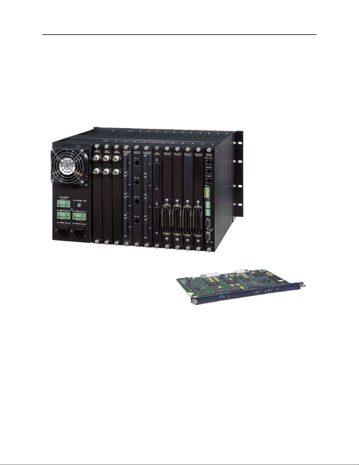
Installing Application & Interface Modules
Figure 20: DNX-11 and an application module pictured below.
To install application and interface modules into a DNX-11 chassis:
1. Remove the application module and corresponding rear interface card fr om the anti-static
bags.
2. Hold the front application module upright and slide it into a slot in the DNX chassis following
the white card guide.
3. Next, hold the rear interface card upright and slide it into the rear of the DNX chassis
following the white card guide. Make sure it is aligned with the front application module.
4. When both cards are aligned and inserted, properly fasten the thumb screws securely in
both front and rear cards. If done properly, the module will reset.
DOC-001-11001 (Rev. 006)
25 DNX Quick Install & Setup Guide
Page 34
Connecting External Clocking SMC II Module Jumper Configuration
Station Clk
CC
PSX
A1
A2
B1
B2
NC
NO
C
NO
NC
C
NO
NC
C
1
3
2
Alarm
T1/E1
C1
C2
D1
D2
Composite Clock
Inputs A & B
T1/E1 BITS Clock
Inputs C & D
Directly Wired Connection
Wire-Wrapped Connection
Terminal Strip (Supplied)
SMC IIA
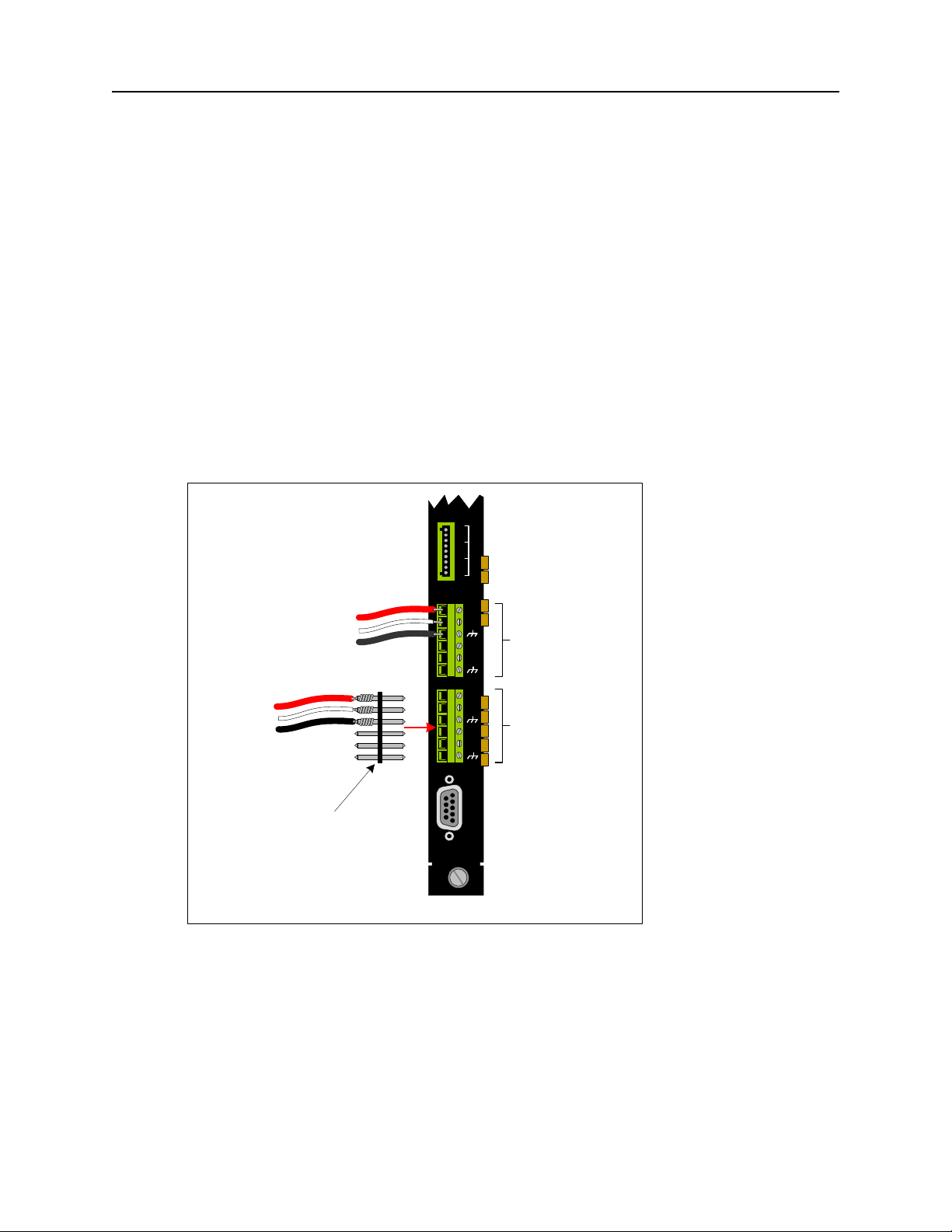
Connecting External Clocking
External Clocking can be supplied via two source connectors provided on th e new SMC IIA rear
interface module to enable the DNX to receive clock inputs from specific external timing
sources. The SMC IIA rear interface module provides a composite clock connector that can be
connected to two 64kbps composite clock inputs, and a T1/E1 clock connector input which can
be connected to two T1 (1.544mbps) or E1 (2.048mbps) BITS clock inputs. Connections can
be made either directly to the terminal block or via a wire-wrapped connection using the supplied terminal strip. See Figure 21 for connection details.
Note: These clock inputs must be selected as a primary , seconda ry, or tertiary source prior to
configuring the clocking mode or they will not be recognized.
Figure 21: SMC IIA Clock Input Connections.
DOC-001-11001 (Rev. 006)
For further details on clocking, please refer to the DNX-11/-4 Reference and User’s Guide or
DNX-88 Reference and User’s Guide.
26 DNX Quick Install & Setup Guide
Page 35
PSX-5300 Installation SMC II Module Jumper Configuration
PSX-5300 Installation
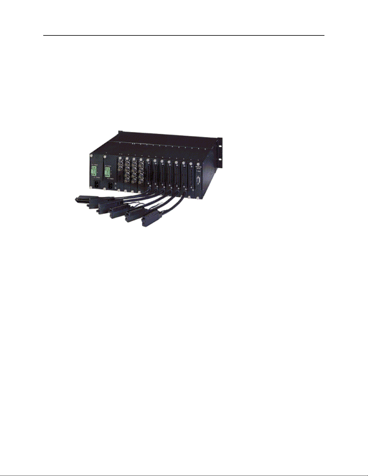
This section will guide you through installing the PSX-5300 N+1 Protection Switch, installing
modules, and configuring Network Redundancy.
Figure 22: N+1 Protection Switch (rear view).
DOC-001-11001 (Rev. 006)
27 DNX Quick Install & Setup Guide
Page 36
PSX-5300 Installation Rack Mounting
Rack Mounting
Screws
DNX-11
Chassis
PSX-5300 and
Mounting Bracket
Rack Mounting
Ensure that you have 3RU (5.25"/133mm) of empty rack space ab ove the DNX unit in which to
install the PSX-5300.
1. Securely mount the N+1 Protection Switch in the equipment rack, directly above the DNX-
11.
Proper Grounding
Grounding via Rack Mount
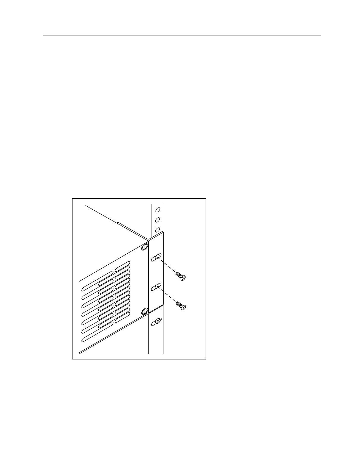
1. Securely mount the PSX-5300 directly above the DNX-11 in the equipment rack using rack
mounting screws (supplied) as shown in Figure 23.
Note: The PSX-5300 may be flush mounted or center mounted in a 19” or 23” equipment
rack. See the PSX-5300 Reference & User's Guide for details.
Figure 23: Grounding via Rack Mount.
DOC-001-11001 (Rev. 006)
28 DNX Quick Install & Setup Guide
Page 37
PSX-5300 Installation Rack Mounting
DC POW ER
+
-
WARNI NG
Remo ve Pow e r Cab le
Before Removing Module
FUSE: F2A - 250VAC
DC POW ER
+
-
WARNI NG
Remo ve Pow e r Cab le
Before Removing Module
FUSE: F2A -250VAC
OUT TX
RX
BB-E/R
Grounding Strap
External-Toothed
Lockwashers
#10-32
Screws
Grounding via Grounding Strap
Note: This is the most reliable method of grounding the PSX-5300.
1. Securely mount the PSX-5300 directly above the DNX-11 in the equipment rack as shown
in Figure 23.
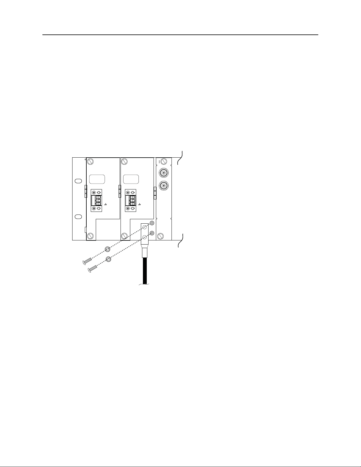
2. Using two #10-32 screws and external-toothed lockwashers (provided), connect a
grounding strap lug to the grounding points near the power terminal block as shown in
Figure 24.
Figure 24: Grounding via Grounding Strap
DOC-001-11001 (Rev. 006)
29 DNX Quick Install & Setup Guide
Page 38

PSX-5300 Installation PSX-5300 DC Power
PSX-5300 DC Power
To take advantage of the redundant power supplies, use two separate -48 volt DC power
connections from two separate fuse panels or from a fuse panel with redundant (A and B) fuse
positions.
DC Power Requirements
The PSX-5300 is designed to operate on -43.2 to -52.8 volt DC power, at a maximum of 48
watts. Requirements for the actual power connection are as follows:
• The supply wiring should be 12 to 18 AWG.
• The -48 VDC supply should be electrically isolated from any AC source.
• The -48 VDC source should be reliably connected to earth ground.
• A readily accessible disconnect device must be incorporated in the building installation or
local wiring.
• The PSX-5300 shall be installed in accordance with 110-16, 110-17, and 110-18 of the
National Electrical Code, ANSI/NFPA No. 70.
DC Power Fuse
The PSX-5300 DC power supply contains a 2A, 250V Fast-Acting fuse.
DOC-001-11001 (Rev. 006)
30 DNX Quick Install & Setup Guide
Page 39
PSX-5300 Installation PSX Module Installation and Cable Connection
PSX Module Installation and Cable Connection
1. Install the Protection Switch Controller module.
2. Connect the DB9 male-to-male Serial Interface Cable to the DB9 connector on the PSX
Controller module.
3. Connect the opposite end to the DB9 connector located System Manager Rear Interface
Module, marked Protect Swt (SMC II) or PSX (SMCII A).
4. Install the primary and redundant interface modules.
Note: The Primary and Redundant Interface modules have a one-to-one correspondence
with the DNX-11 Interface modules; see Table 2.
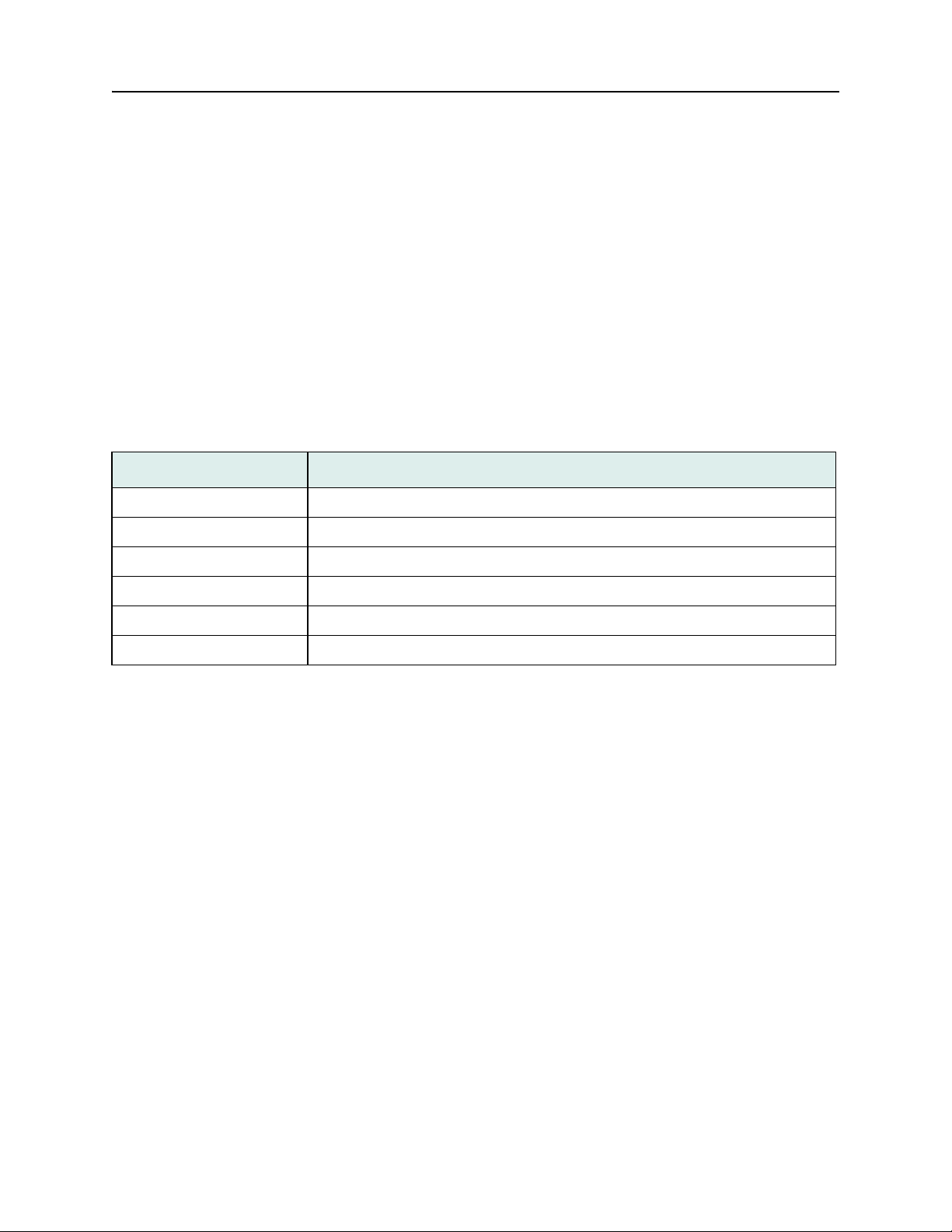
Table 2: One-to-one Correspondence.
Slot Module
Slot 1: Narrowband (e.g., Octal T1/E1) Redundant Card
Slots 2-1 1: Narrowband (e.g., Octal T1/E1) Primary Card
Slot 11: Broadband Group 1 (e.g., HDS3) Redundant Card
Slots 8-10: Broadband Group 1 (e.g., HDS3) Primary Card
Slot 7: Broadband Group 2 (e.g., STS1) Redundant Card
Slots 1-6: Broadband Group 2 (e.g., STS1) Primary Card
For details on connecting Narrowband and Broadband modules, refer to “Narrowband Cable
Connections” on page 32 or “Broadband Cable Connections” on page 32.
DOC-001-11001 (Rev. 006)
31 DNX Quick Install & Setup Guide
Page 40
PSX-5300 Installation PSX Module Installation and Cable Connection
SM1234567891011POWER
CTL
POWER
N+1 Protection SwitchDNX-11
Links 1-8Links 9-16
NARROWBAND BUS (10+1)
1
1
2 2
3
Narrowband Cable Connections
1. Connect the 50-pin cable from the network to the 50-pin connector that is on the PSX
Narrowband Primary module.
2. Connect the 50-pin cable from the Narrowband Primary module to the corresponding 50-pin
connector that is on the DNX Narrowband (Octal T1/E1) rear interface module.
3. Attach the 50-pin male-to-male cable (part # CBE-048-50501) from the Narrowband
Redundant module to the Standby slot 1 on the DNX-11.
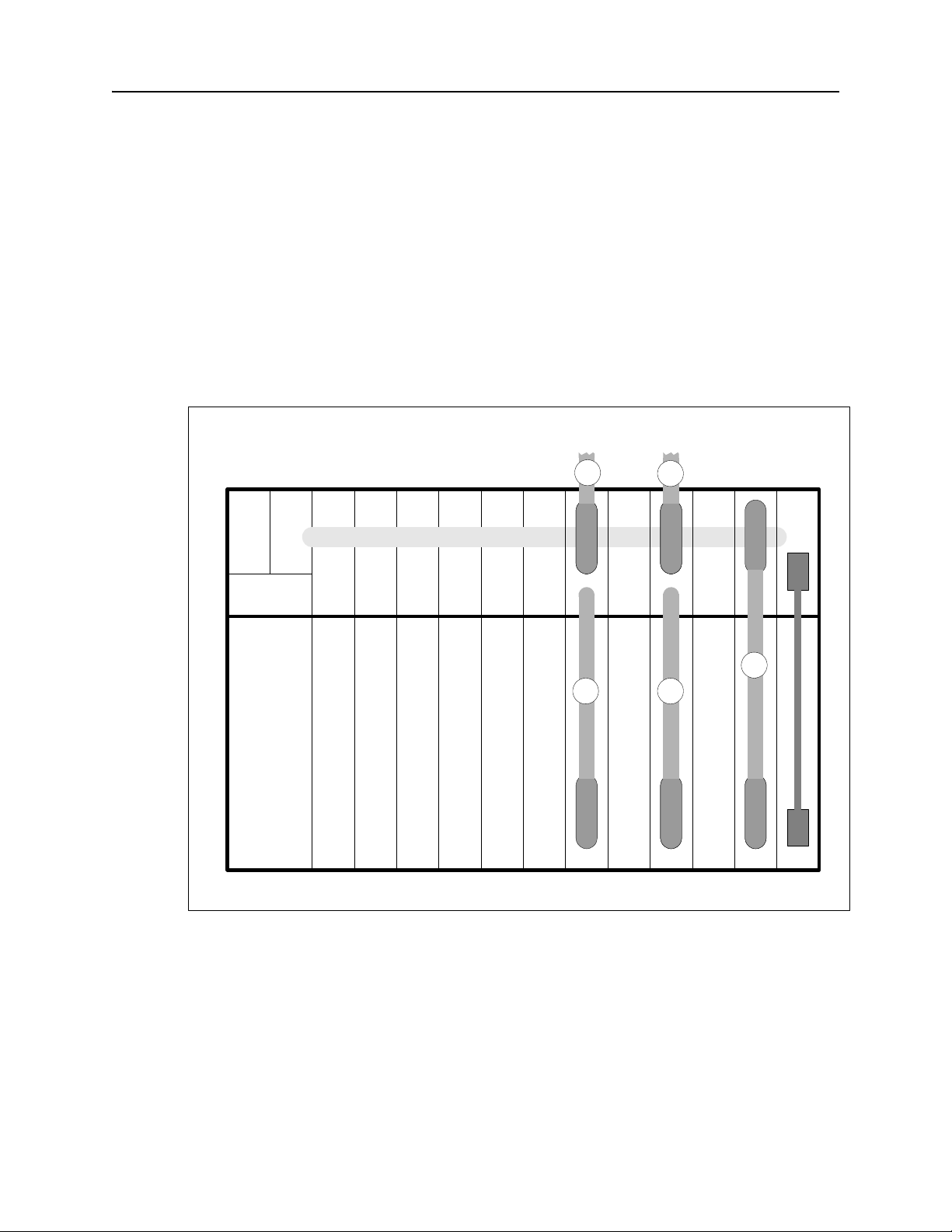
Figure 25 illustrates a PSX connection for Narrowband Redundancy.
Figure 25: PSX Narrowband Cable Installation.
Figure Notes: In Figure 25, slots 3 and 5 contain Narrowband primary interface modules, and
slot 1 contains the Narrowband Group b ackup module. The nu mbers on the cables corre spond
to the steps in the Narrowband Connection procedure above.
Note: To power up, refer to ““Connecting N+1 Protection Switch DC Power (-48VDC)”” on
page 35.
DOC-001-11001 (Rev. 006)
32 DNX Quick Install & Setup Guide
Page 41

PSX-5300 Installation PSX Module Installation and Cable Connection
Broadband Cable Connections
1. Connect the RX BNC cable from the network to the "IN" RX jack on the PSX Broadband
Primary module and the TX BNC cable to the network to the "IN" TX jack.
2. Connect one of the BNC attachment cables (part # CBE-002-75015) between the PSX
Primary "OUT" TX and the RX port of the corresponding broadba nd interface mo dule in the
DNX.
3. Connect another BNC attachment cable (part # CBE-002-75015) between the PSX Primary
"OUT" RX and the TX port of the corresponding broadband interface module in the DNX.
4. Connect another BNC cable (part # CBE-002-75015) between the RX port of the PSX
Broadband Redundant module and the TX port of the corresponding back-up broa dband
interface module in the DNX.
5. Connect another BNC cable (part # CBE-002-75015) between the TX port of the PSX
Broadband Redundant module and the RX port of the corresponding back-up broadband
interface module in the DNX.
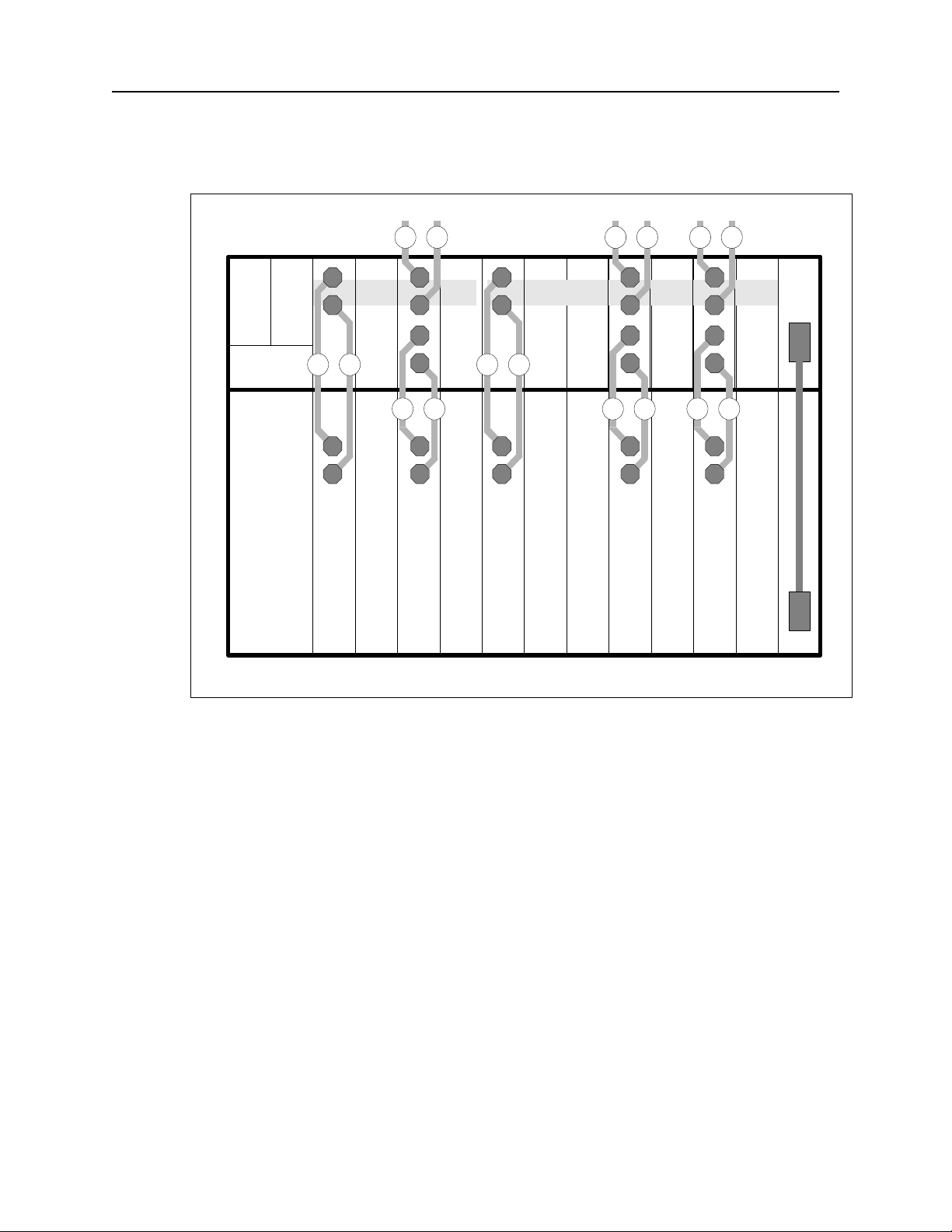
Figure 26 on the following page illustrates a PSX connection for Broadband Redundancy.
DOC-001-11001 (Rev. 006)
33 DNX Quick Install & Setup Guide
Page 42
PSX-5300 Installation PSX Module Installation and Cable Connection
SM1234567891011POWER
CTL
POWER
N+1 Protection Swit chDNX-11
BB1 BB2
R
T
OUT
T
R
IN
R
T
1 1
2 3
OUT
T
R
R
T
5 4
OUT
T
R
R
T
5 4
R
T
OUT
T
R
IN
R
T
1 1
2 3
R
T
OUT
T
R
IN
R
T
1 1
2 3
Figure 26: PSX Broadband Cable Installation.
Figure Notes: In Figure 26, slot 9 contains a Broadband Group 1 primary interface module,
and slot 1 contains the Broadband Group 1 backup module. Slots 2 and 4 contain Broadband
Group 2 primary interface modules, and slot 7 contain s the Broadband Group 2 backup module.
The numbers on the cables correspond to the steps in the Broadban d Connection procedure on
the previous page.
Note: T o power up, refer to ““Connecting N+1 Protection Switch DC Power (-48VDC)”” on the
following page.
DOC-001-11001 (Rev. 006)
34 DNX Quick Install & Setup Guide
Page 43
PSX-5300 Installation PSX Module Installation and Cable Connection
DC POWER
+
-
WARNING
Remove Power Cable
Before Removing Module
FUSE: F2A - 250VAC
Connecting N+1 Protection Switch DC Power (-48VDC)
Note: T o in su re DC power re dun dancy is ma intained, use two DC Power Supply Modules, in
conjunction with power sources from two separate fuse panels or from a fuse panel
with redundant (A and B) fuse positions.
1. Mount the unit above a DNX-11 unit in a rack as specified previously.
2. Shut off -48VDC power to the DC supply leads.
3. Strip the insulation back approximately 5/16 inch (8mm) from the end of each lead.
4. Note the positions of earth, negative and positive on the DC power plug (designations are
on the DC Power Supply Module faceplate).
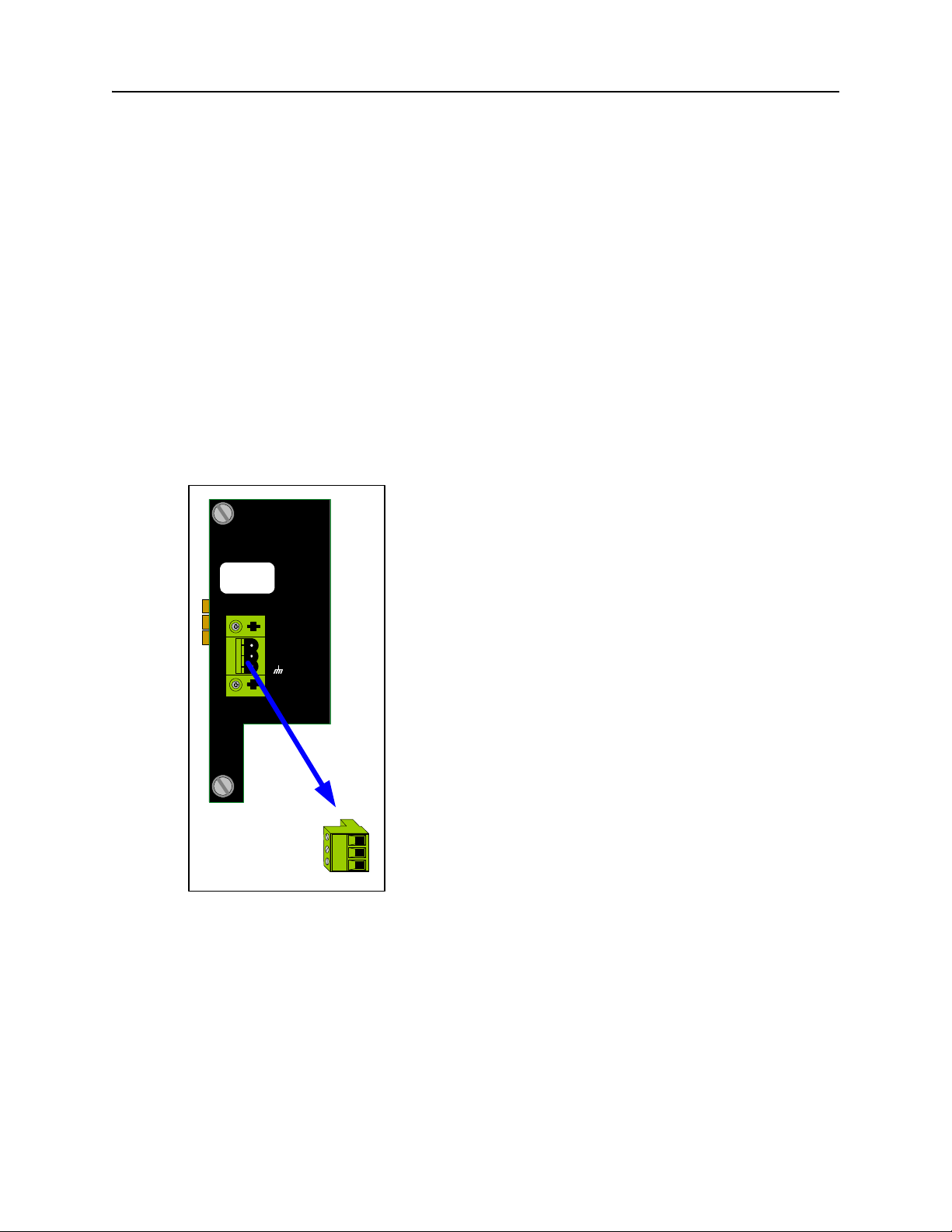
5. Remove the DC power terminal block from the mating receptacle on the DC Power Supply
Module faceplate (see Figure 27).
Figure 27: Remove Power Terminal Block.
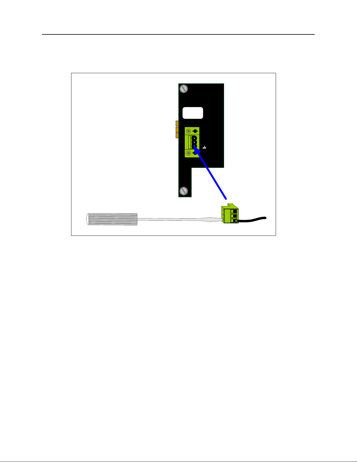
6. Insert the “earth” lead into the earth terminal clamp on the power terminal block and tighten
the clamp screw using a small flat screwdriver (see Figure 28).
DOC-001-11001 (Rev. 006)
35 DNX Quick Install & Setup Guide
Page 44
PSX-5300 Installation PSX Module Installation and Cable Connection
DC POWER
+
-
WARNING
Remove Power Cable
Before Removing Module
FUSE: F2A - 250V A C
Figure 28: Connecting DC Power Leads.
7. Insert the “-48 volt supply” wire into the negative terminal clamp and tighten the clamp
screw.
8. Insert the “return” wire into the positive terminal clamp and tighten the clamp screw.
9. Insert the power terminal block into the mating receptacle on the rear panel (see Figure 28).
10. Repeat steps 2-9 if the PSX-5300 has a second (redundant) DC Power Supply Module
installed.
11. To minimize disturbance to the wires through casual contact, secure the power cables to
the rack frame using multiple cable ties. The first tie should be located within 6 inches of
the terminal block.
12. Power up both the DNX-11 and N+1 Protection Switch. The LED on the PSX Controller
Module will flash as the unit powers up, loads software, and runs a self-test. This will take a
few minutes, depending upon how many modules have been configured.
13. Once the system is powered up, you should see a flashing
Protection Switch Controller module; a solid
a flashing
Green READY LED on the Standby SMC II.
Green READY LED on the Online SMC II; and
Green READY LED on the N+1
Note: Ignore any alarms at this point.
To verify the protection switch installation, refer to “Verifying Protection Switch Installation” on
page 44.
DOC-001-11001 (Rev. 006)
36 DNX Quick Install & Setup Guide
Page 45

System Visual Inspection PSX Module Installation and Cable Connection
System Visual Inspection
Once all of the modules have been installed, power up the system. The LED(s) shou ld be lit on
the power supply module(s), the “READY” LED should be lit on the on the SMC m odule(s), a nd
the READY LED should be lit on each application module.
DOC-001-11001 (Rev. 006)
37 DNX Quick Install & Setup Guide
Page 46
Console Management Access PSX Module Installation and Cable Connection
Console Management Access
Use the console to configure the interface protocol and parameters for each device port, monitor the network, and perform diagnostics. A console may be a PC, workstation or a dedicated
terminal. Access to the console is password-protected after you establish a login and password. Telnet is supported as well as direct connection to the asynchronous port.
Connecting the Console
The necessary cable that attaches to the connectors should be installed at your site. For pin
assignments and descriptions of these interfaces, refer to the DNX Accessories Guide.
A console may be connected to the DNX in any of the following three ways:
• Telnet access from a PC or workstation via an Ethernet LAN.
• Dial call to the DNX‘s modem port from any PC or workstation on the network.
• Dedicated terminal connected to the DNX’s console port.
To Connect a Console:
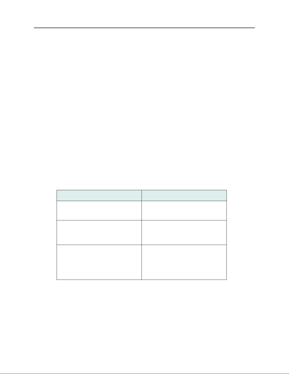
1. Locate the DNX System Manager Interface on the rear of the chassis, then refer to Table 3.
Table 3: Console Connections.
If Then
an asynchronous terminal (or pc with VT100 emulation) will be directly connected
to the DNX ...
a PC or workstation in the network will dial
in to the DNX ...
a PC or workstation in the network will use
an Ethernet cable to connect to the DNX
...
2. Configure your terminal communications parame ters as follows:
•
Data Rate: 1200, 2400, 4800, 9600 or 19200 bps (9600 recommended)
... locate the RJ-11 craft interface connector labeled TERM. Attach your termin al to
this connector.
... locate the RJ-11 telco connector
labeled PHONE LINE. Insert a phone line
in this connector. The DNX has a built-in
modem.
... connect the LAN using the Ethernet
connector marked
10/100BaseT (SMC IIA) on the DNX Sys-
tem Manager interface. The Administrator
establishes a Telnet session to connect to
the DNX.
10 Base T (SMC II) or
•
Data Bits: 8
•
Stop Bit: 1
•
Parity: None
•
Flow Control: None
DOC-001-11001 (Rev. 006)
38 DNX Quick Install & Setup Guide
Page 47

Console Management Access PSX Module Installation and Cable Connection
Note: Some terminal manufacturers might identify the data bit configuration as 7-N-1 (seven
data bits plus a “not used” p arity bit) while other manufacturers might identify the same
configurations 8-N-1 (eight bits including a “not used” parity bit). Check the terminal’s
user manual.
DOC-001-11001 (Rev. 006)
39 DNX Quick Install & Setup Guide
Page 48

Console Management Access PSX Module Installation and Cable Connection
Logging into the DNX
1. Press <Enter> on your terminal keyboard to activate automatic baud rate recognition
(ABR).
2. Enter your login name and password. To use the default login name and password, press
<Enter>
for each entry.
Note: Once a login name and password has been established, the default login (Enter) is no
longer valid. The Admin user level should establish the first login name and p a sswor d
entry on the User Menu. For more details on the various security levels, refer to
“System Security” on page 41.
3. If the DNX System Manager cannot automatically detect your terminal type, the Terminal
Selection Menu displays. Select your terminal type from the list. Refer to the screen below .
Figure 29: Terminal Selection Type.
login:
password:
WELCOME...
Thu, Oct 30, 2003 15:38:53pm
os: 3.0
Terminal types supported:
(1) ADDS Regent 25 (11) Hazeltine 1500
(2) ADDS Viewpoint (12) IBM 3101
(3) Attis 4410/4425 (13) ICL 6401
(4) Data General DASHER (14) LSI ADM 11/31
(5) Datamedia 1521 (15) Paradyne 7811
(6) Datamedia EXCEL 30 (16) Qume QVT-101/102/108
(7) Datamedia EXCEL 42 (17) Teletype 5410/5425
(8) DEC VT-52 (18) Televideo 900
(9) DEC VT-100/131/220 (19) Wyse WY-50
(10) Freedom 100 (20) Wyse WY-75
Enter your terminal type [1..20]...
4. Once the terminal type has been automatically detected or manually selected, the DNX
Main Menu displays.
DOC-001-11001 (Rev. 006)
40 DNX Quick Install & Setup Guide
Page 49

System Security PSX Module Installation and Cable Connection
System Security
The DNX provides system security by utilizing four different user-access levels. These are as
follows:
•
Admin - The highest level of access. Users at this level can access all DNX functions and
can add/remove users from the system. The Admin-level user is not able to view another
user’s password, but can delete an d ad d ne w passwords in the event a user has forgotten
his password.
•
Provision - Users at this level can make configuration changes, run diagnostic tests, and
do everything that an Admin-level user can do except add/delete users, change password s,
or download software.
•
Test - Users at this level have all of the privileges of a View Only user, plus the ability to
perform testing such as initiating/terminating BERT tests and loopbacks, clearing
performance registers, etc.
•
View O nly - Users at this level can view some system settings, options, and alarm
information but cannot change any settings.
Refer to the DNX-11/-4 Reference and User’s Guide or DNX-88 Reference and User’s Guide
for a full description of system security levels.
DOC-001-11001 (Rev. 006)
41 DNX Quick Install & Setup Guide
Page 50

Install IP Address PSX Module Installation and Cable Connection
Install IP Address
Port IP Address Configuration
The Port Configuration Menu is used to configure the TCP/IP stack in the DNX and contr ol its IP
address and how it behaves on your 10BaseT LAN segment. These options only affect the
10BaseT (SMC II) or 10/100BaseT (SMC IIA) port operation, they are not directly related to the
flow of user data through the DNX.
1. From the DNX Main Menu, place your cursor on the System Configuration field and press
<Enter>. The Node Configuration Menu appears.
2. From the Node Configuration Menu, place your cursor on the Port IP Addresses field and
press
<Enter>. The following screen appears.
Figure 30: Port Configuration Menu.
Eastern Research, Inc. DNX 11 - Node Manager Help = [?]
Port Configuration Menu
IP encapsulation.................: Ethernet II
LAN IP address...................: 0.0.0.0
LAN IP mask......................: 0.0.0.0
Enable RIP.......................: No
Default gateway (if RIP disabled): 0.0.0.0
Changes to IP encapsulation, LAN IP address or LAN IP mask
will cause open telnet sessions to be closed.
3. Move your cursor to applicable fields to specify information on the Port Configuration Menu;
for details refer to Table 4 on the following page.
4. When configuration is complete, press
prompted “Update Configuration?”, press
DOC-001-11001 (Rev. 006)
X to save and exit to the previous menu. When
Y to save and exit.
42 DNX Quick Install & Setup Guide
Page 51
Install IP Address PSX Module Installation and Cable Connection
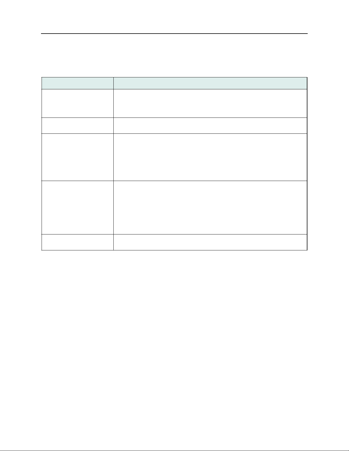
Table 4: Port IP Address Field Descriptions.
Field Description
IP Encapsulation:
field)
LAN IP Address: (text
field)
LAN IP Mask: (text field) The LAN IP mask is a 32-bit number represented in the sa me way as the IP
Enable RIP: (option field) This parameter enables/disables RIP (Routing Information Protocol) on the LAN
Default Gateway: (option
field)
(option
The choices are
should select Ethernet II for the encapsulation type. 802.3 encapsulation is used
most often on LANs running Novell Netware. Your selection should match that
used by other IP workstations and hosts on the LAN.
This parameter is used to specify the LAN IP address of the DNX. Consult your
network administrator to obtain a valid IP address for your DNX.
address. A default mask is automatically generated; however, it can be overwritten
to support subnetting. Subnetting allows you to allocate bits from the host portion
of the IP address as an extension to the address. Depending on the type of IP network you are using (Class A, B or C), the subnet mask may be 24, 16 or 8 bits in
length. Typically, the first three octets of the address defines the network address.
The last octet defines the specific device.
port. If the DNX will always use the same IP address (router interface) to reach
other segments you should leave Enable RIP set to
router (gateway) information. You should enable RIP only if you want the DNX to
discover the devices available on the local LAN segment. Since RIP uses System
Manager resources which might otherwise be used to manage the DNX nest, you
should consider leaving RIP off and manually configuring a gateway address,
especially in a high traffic LAN environment.
This is the IP address of the router or switch where DNX should send packets if
their destination is located on another LAN segment.
Ethernet II or 802.3. If your LAN is using standard TCP/IP you
No and manually configure the
DOC-001-11001 (Rev. 006)
43 DNX Quick Install & Setup Guide
Page 52

Verifying Protection Switch Installation PSX Module Installation and Cable Connection
Verifying Protection Switch Installation
To ensure the Protection Switch has been properly installed, verify the Card Status is Ok and
the Switch State’s condition is Normal.
V e rify the Protection Switch Installation
1. From the DNX Main Menu, move your cursor to the Nest Summary field and press <Enter>
The Slot Summary Menu appears:
Figure 31: Slot Summary Menu.
Eastern Research, Inc. DNX 11 - Node Manager Help = [?]
Standby SMC not present N+1 Redundancy State: Enabled
Alarm Contacts..: Enabled Alarm Contact Type..: Standard
Nest #1 Slot Summary Menu
N+1
Slot# Group Configured Type Device State Alarm
----- ----- --------------- ------------ ----01 Octal T1/E1 Online None Clock Src
02 Octal T1/E1 Online None
03 Octal T1/E1 Online None
04 Octal T1/E1 Online None
05 Octal T1/E1 Online None
06 Hybrid DS-3 Online None
07 Hybrid DS-3 Standby None
08 STS-1 Online None
09 STS-1 Online None
10 Hybrid DS-3 Online None
11 Hybrid DS-3 Online None
SMCA System Manager A Standby None
SMCB System Manager B Online None
PSX ProtectionSwitch Online None
[C]lear error counts [T]oggle Alarm Contacts
N+1 Device Redundancy: Switch[O]ver [R]estore [E]xpose
2. Verify that the Protection Switch is Online b y looking in the device state colu mn. Move your
cursor to the PSX field and press
DOC-001-11001 (Rev. 006)
<Enter>. The Protection Switch’s Main Menu appears:
44 DNX Quick Install & Setup Guide
Page 53

Verifying Protection Switch Installation PSX Module Installation and Cable Connection
Figure 32: Protection Switch Main Menu.
Eastern Research, Inc. DNX - Protection Switch Help = [ ?]
Main Menu
---------
Status
Utilities
About
3. Move your cursor to the Status field and press
<Enter>. The Protection Switch’s Status
Menu appears; it should look similar to the one shown in Figure 33.
Figure 33: Protection Switch Status Menu.
Eastern Research, Inc. DNX - Protection Switch Help = [?]
Status Menu
-----------
Slot# Card Type Card Status Switch State Switch Status
-------------------------------------------------------------------------------01 Narrowband Redundant Ok Normal Ok
02 Narrowband Primary Ok Normal Ok
03 Narrowband Primary Ok Normal Ok
04 Narrowband Primary Ok Normal Ok
05 Narrowband Primary Ok Normal Ok
06 Broadband '2' Primary Ok Normal Ok
07 Broadband '2' Redundant Ok Normal Ok
08 Broadband '1' Primary Cable Missing Normal Ok
09 Broadband '1' Primary Ok Normal Ok
10 Broadband '1' Primary Ok Normal Ok
11 Broadband '1' Redundant Ok Normal Ok
Power Supply A Status.: Ok Fan Maintenance: Auto Fan #01: Ok
Power Supply B Status.: Fault Fan Speed......: Low Fan #02: Ok
Chassis Temperature...: 85 F/29 C Fan #03: Ok
DOC-001-11001 (Rev. 006)
45 DNX Quick Install & Setup Guide
Page 54

Verifying Protection Switch Installation PSX Module Installation and Cable Connection
To expose additional information about the Protection Switch, go back to the Nest Summary
Menu, and at the PSX field, press the
E key . The resu lting screen should look simila r to the one
shown in Figure 34.
Figure 34: Protection Switch Slot Information Display.
Eastern Research, Inc. DNX 11 - Node Manager Help = [?]
Protection Slot Information
----------------------------------------------- ----Major Alarms---
Device........: Online Power Supply A: Ok
Psx Controller: Rev #0 Power Supply B: Ok
Chassis.......: Undetermined Fan 1.........: Ok
Fan 2.........: Ok
Fan 3.........: Ok
PSX Interface Card Alarms
01=None 02=None 03=None 04=None 05=None 06=None
07=None 08=None 09=None 10=None 11=None
The screen above shows the Protection Switch is online, and operating with the Rev 0 Controller Module. In this case, the chassis is ‘Undetermined’ because a Rev 0 Controller Module
cannot determine the chassis type. In order to enable a second broadband group, you must
physically look at your PSX chassis label to find out if you have a PSX-5200 or PSX-5300 chassis. Once that determination has been made, go to the Nest Profile Menu, which is displayed
on the following page. The information contained on the Protection Slot Information Display is
listed in Table 5.
DOC-001-11001 (Rev. 006)
46 DNX Quick Install & Setup Guide
Page 55
Verifying Protection Switch Installation PSX Module Installation and Cable Connection
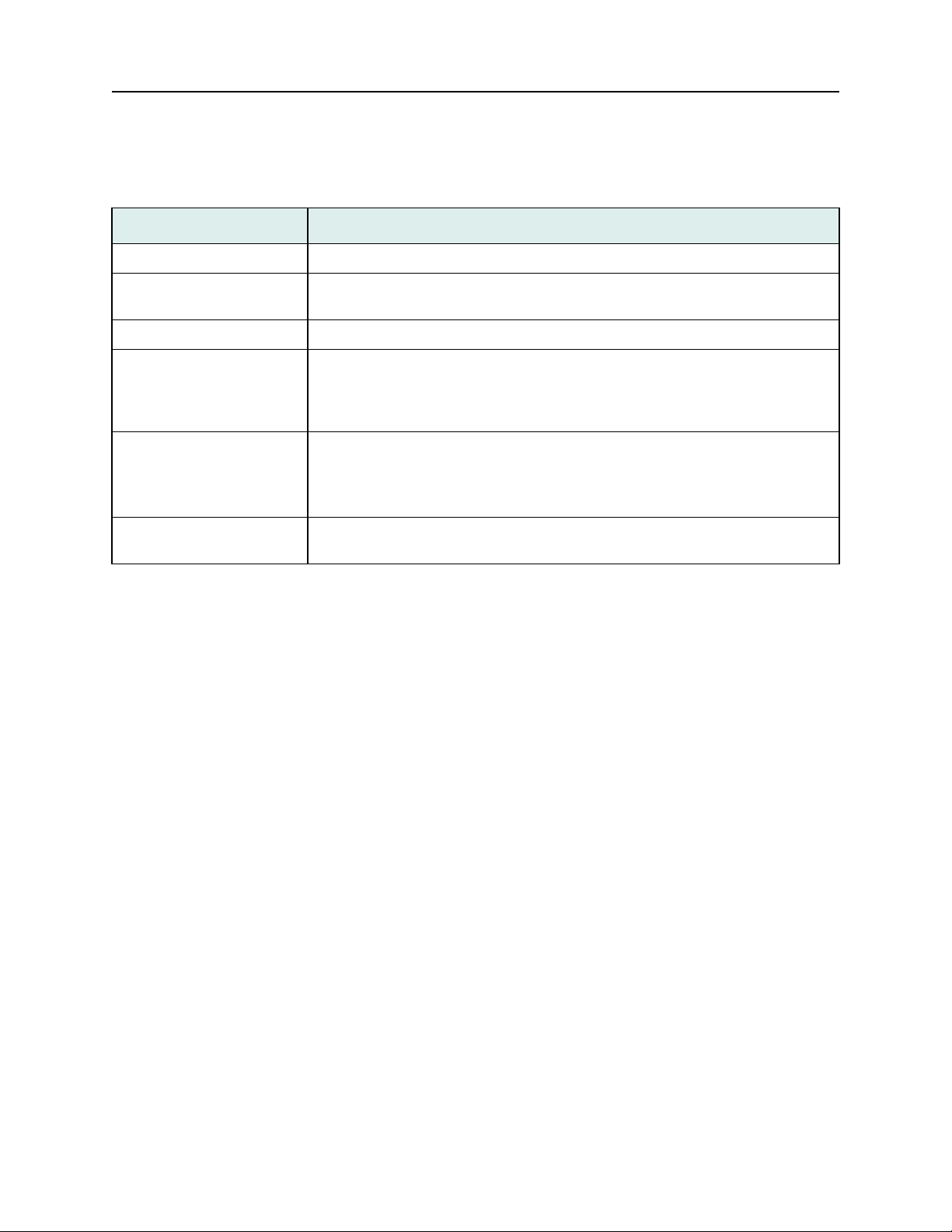
Table 5: Protection Slot Information Display Field Descriptions.
Field Description
Device:
Psx Controller: (display
field)
Chassis: (display field) Displays the type of chassis as PSX-5200 or PSX -5300.
Power Supply A or B:
(display field)
(display field) Displays the state of the PSX as Online or Offline.
Displays the revision level of the PSX Controller Module.
Displays the status of Power Supply A or B as one of the following:
• Ok
• Fault
Fan 1, 2, or 3: (display field) Displays the status of Fan 1, 2, or 3 as one of the following:
• Ok - Fan is operating properly.
• Fault - Fan has been shut off, or is otherwise inoperative.
PSX Interface Card
Alarms:
(display field)
Displays the status of each of the 11 slots in the PSX-5300.
DOC-001-11001 (Rev. 006)
47 DNX Quick Install & Setup Guide
Page 56

Verifying Protection Switch Installation PSX Module Installation and Cable Connection
Verify the Protection Switch Profile Settings
From the DNX Main Menu, select System Configuration, then Nest Profile. The resulting
screen should look similar to the one shown in Figure 35.
Figure 35: Nest Profile Menu.
Eastern Research, Inc. DNX 11 - Node Manager Help = [?]
Nest #1 : Profile
Nest name: Node Mgr. Unit I
Nest type:.............................: DNX11
Dual System Mgr........................: No
Alarm Contacts Type....................: Standard
Number of Rings for Modem Auto-Answer..: 2
Nest Dual Power Supplies...............: No
Block Cfg Change Which Affects Traffic.: No
N+1 Redundancy Nest....................: Yes
Protection Switch Dual Power...........: No
N+1 Redundancy Narrowband Group........: Octal T1/E1
N+1 Redundancy Broadband Group 1.......: HDS-3
Protection Switch Dual Broadband Groups: Yes
N+1 Redundancy Broadband Group 2.......: HDS-3
N+1 Chassis Type.......................: 5300
Carefully read each field on this menu, and set up your system based on your equipment and
software. If you have redundancy, select Yes on the N+1 Redundancy Node field. If you want
to enable a second broadband group, select Yes at the Protection Switch Dual Broadband
Groups field. A new field, N+1 Redundancy Broadband Group 2, will appear. Establish which
type of broadband devices you want to include for Broadband Gr oup 1 and Broadband Gr oup 2.
Note: If you have a Rev 0 Controller Module and PSX 2.3 (or greater) software, you will need
to specify PSX-5300 chassis at the N+1 Chassis Type field in order for your system to
support the second broadband bus. Save your configuration and return to the Nest
Summary Menu. At the Protection Switch field, press
Switch slot information. The Chassis field will show ‘Determined’ as long as you
selected 5300.
DOC-001-11001 (Rev. 006)
E to expose the Protection
48 DNX Quick Install & Setup Guide
Page 57

Maintenance & Repair Routine Maintenance
Maintenance & Repair
Routine Maintenance
Periodic maintenance consists of cleaning the unit as necessary with a moist, lint-free cloth. Do
not use solvents.
Equipment Repair and Return
Sycamore Networks offers Rep air and Replacem ent services to minimize your downtime due to
equipment malfunction. If advice or assistance is required, contact the Sycamore Networks
Technical Assistance Center (TAC) at 1-877-526-2321. Repair/Replacement will be performed
in accordance with the Limited Warranty statement on the Sycamore Networks website.
If the unit has been found defective or in need of repair, Sycamore Networks will issue an RMA
(Return Material Authorization) number. You can also complete the Re pair/Replac em e nt Card
included with your unit and ship the defective eq uip ment with the car d enclosed in the package
and the RMA number prominently displayed on the outside of the p ackage. For best equipment
protection, use the original cartons and packaging material. Send the unit to:
Sycamore Networks, Inc.
121 Whittendale Drive
Moorestown, NJ 08057
ATTN: RMA # ____________
When calling for repair or replacement, the following information is required:
• Equipment model number
• Equipment serial number
• Brief description of problem symptoms and application
• Return shipping address (including sender’s name)
• Invoice address
• Person to contact for further information (plea se include telephone numb er with area code).
DOC-001-11001 (Rev. 006)
49 DNX Quick Install & Setup Guide
Page 58

Maintenance & Repair Equipment Repair and Return
THIS PAGE INTENTIONALLY LEFT BLANK.
DOC-001-11001 (Rev. 006)
50 DNX Quick Install & Setup Guide
Page 59

Maintenance & Repair Equipment Repair and Return
DOC-001-11001 (Rev. 006)
51 DNX Quick Install & Setup Guide
Page 60

Appendix A
Regulatory Information
North America
This equipment complies with the requirements in Part 15 of FCC Rules for a Class A
computing device. Operation of this equipment in a residential area may cause unacceptable
interference to radio and television reception, requir ing the operator to take whatever steps are
necessary to correct the interference. Shielded cables should be used with this unit to ensure
compliance with the Class A limits.
In order for the DNX-11, DNX-88, and the N+1 Protection Switch to remain compliant with the
various emissions regulations, unpopulated slots in the nest should be covered with blank
panels.
For Regulatory Information on a specific DNX module, please refer to the separate Useer’s
Guide for that module.
This Class A digital apparatus meets all requirements of the Canadian Interference-Causing
Equipment Regulations.
Note: The modem connection is only approved for use in North America.
FCC Customer Information
This equipment complies with Part 68 of the FCC rules. On the back or side of this equipment is
a label that contains, among other information, the FCC certification number and ringer
equivalence number (REN) for this equipment. If requested, this information must be provided
to the telephone company.
For single and two-line connections to the telephone network, the plug and jack used with this
equipment must comply with FCC Part 68 rules. See Installation Instructions for details.
If this equipment causes harm to the telephone network, the telephone company will notify you
in advance that temporary discontinuance of se rvic e ma y be requir ed . But if adva nc e no tice
isn't practical, the telephone company will notify the customer as soon as possible. Also, you
will be advised of your right to file a complaint with the FCC if you believe it is necessary.
The telephone company may make changes to its facilities, equipment, operations or
procedures that could affect the operation of the equipment. If this happens the telephone
company will provide advance notice so you can make the necessary modifications to maintain
uninterrupted service.
If trouble is experienced with this equipment, for repair or warranty information, please contact
the Sycamore Networks Technical Assistance Center (TAC) at 1-877-526-2321. If the
equipment is causing harm to the telephone network, the te leph one company may request that
you disconnect the equipment until the problem is resolved.
DOC-001-11001 (Rev. 006) A–1 DNX Quick Install & Setup Guide
Page 61

Appendix A - Regulatory Information North America
Affidavit Requirements For Connection To Digital Services
• An affidavit (see next page for format) is required to be given the telephone company
whenever digital terminal equipment without encoded analog content and billing protection
is used to transmit digital signals containing encoded analog content which are intended for
eventual conversion into voiceband analog signals and retr ansmitted on the network.
• The affidavit shall affirm that either no encoded analog content or billing information is being
transmitted or that the output of the device meets Part 68 encoded analog content or billing
protection specifications.
• The end user/customer will be responsible to file an affidavit with the local exchange carrier
when connecting unprotected CPE to a 1.544 Mbps or sub-rate digital services.
• Until such time as subrate digital terminal equipment is registered for voice applications, the
affidavit requirement for subrate services is waived.
DOC-001-11001 (Rev. 006)
A–2 DNX Quick Install & Setup Guide
Page 62

Appendix A - Regulatory Information North America
AFFIDAVIT FOR CONNECTION OF CUSTOMER PREMISES EQUIPMENT TO
1.544 MBPS AND/OR SUBRATE DIGITAL SERVICES
For the work to be performed in the certified territory of ___________________________ (Telco name).
State of ______________________
County of ____________________
I, _________________________________ (name) _____________________________________________________ (business
address) _______________________ (telephone number) being duly sworn, state:
I have responsibility for the operation and maintenance of the terminal equipment to be connected to 1.544 Mbps and/or _______
subrate digital services. The terminal equipment to be connected complies with Part 68 of the FCC rules except for the encoded analog content and billing protection specifications. With respect to encoded analog content and billing protection:
( ) I attest that all operations associated with the establishment, maintenance and adjustment of the digital CPE with respect to analog content and encoded billing protection information continuously complies with Part 68 of the FCC Rules and Regulations.
( ) The digital CPE does not transmit digital signals containing encoded analog content or billing information which is intended to be
decoded within the telecommunications network.
( ) The encoded analog content and billing protection is factory set and is not under the control of the customer.
I attest that the operator(s)/maintainer(s) of the digital CPE responsible for the establishment, maintenance and adjustment of the
encoded analog content and billing information has (have) been trained to perform these functions by successfully having completed
one of the following:
(Check appropriate blocks):
( ) A. A training course provided by the manufacturer/grantee of the equipment used to encode analog signals; or
( ) B. A training course provided by the customer or authorized representative, using training materials and instructions provided by
the manufacturer/grantee of the equipment used to encode analog signals; or
( ) C. An independent training course (e.g. trade school or technical institution) recognized by the manufacturer/grantee of the equipment used to encode analog signals; or
( ) D. In lieu of the proceeding training requirements, the operator(s)/maintainer(s) is (are) under the control of a supervisor trained in
accordance with _______(circle one) above.
I agree to provide ______________________________(Telco name) with proper documentation to demonstrate compliance with the
information as provided in the preceding paragraph, if so requested.
Signature_________________________________________
Title_____________________________________________
Date_____________________________________________
Subscribed and sworn to before me
This _____________ day of _______________________, 20____
Notary Public
My commission expires:
DOC-001-11001 (Rev. 006)
A–3 DNX Quick Install & Setup Guide
Page 63

Appendix A - Regulatory Information North America
Industry Canada Statement
NOTICE: The Industry Canada label identifies certified equipment. This certification
means that the equipment meets certain telecommunications network protective, operational
and safety requirements as prescribed in the appropr i at e Terminal Equipment Technica l
Requirements document(s). The Department does not guarantee that the equipment will
operate to the user’s satisfaction.
Before installing this equipment, users should ensure that it is permissible to be connected to
the facilities of the local telecommunications company. The equipment must also be installed
using an acceptable method of connection. The customer should be aware that compliance
with the above conditions may not prevent degradation of service in some situations.
Repairs to certified equipment should be coordinated by a representative designated by the
supplier. Any repairs or alterations made by the user to this equipment, or equipment
malfunctions, may give the telecommunications company cause to request the user to
disconnect the equipment.
Users should ensure for their own protection that the electrical ground connections of the power
utility, telephone lines and internal metallic water pipe system, if present, are connected
together. This precaution may b e particularly important in rural areas.
CAUTION: Users should not attempt to make such connections themselves, but should
contact the appropriate electric inspection authority, or electrician, as appropriate.
NOTICE: The Ringer Equivalence Number (REN) assigned to each terminal device
provides an indication of the maximum number of terminals allowed to be connected to a
telephone interface. The termination on an interface may consist of any combination of devices
subject only to the requirement that the sum of the Ringer Equivalence Numbers of all the
devices does not exceed 5.
Product Safety
This equipment meets the safety requirements of the Underwriters’ Laboratories (UL) technical
publications UL 1950, Third Edition, CAN/CSA-C22.2 No. 950-95, Third Edition, and
EN60950:1992.
DOC-001-11001 (Rev. 006)
A–4 DNX Quick Install & Setup Guide
Page 64

Appendix A - Regulatory Information Europe
Europe
This equipment has been designed to be in conformity with the following standard(s) or other
normative document(s):
EN55022, Class A, 1994
EN55024:1998
EN50082-1:1991
EN 300 386-2:1997
EN60950:1992
CTR 12/A1
following the provisions of the EMC directive 89/336/EEC, the Low voltage directive 73/23/EEC,
and the R&TTE directive 1995/5/EC.
Product Recycling And Disposal
This product is not intended to be used in private households.
Do not discard this product in public waste facilities. European Union Directive 2002/96/EC
requires the recycling of this product at the end of its useful life.
This product contains materials such as circuit boards which may contain lead and other
materials that require special handling. It also may contain components such as batteries.
Before this unit is disposed of, these materials must be recycled or discarded according to
regional regulations.
Please contact your regional sales office if you need assistance.
DOC-001-11001 (Rev. 006)
A–5 DNX Quick Install & Setup Guide
Page 65
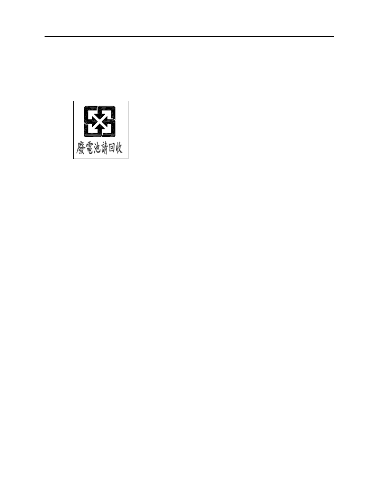
Appendix A - Regulatory Information Taiwan
Taiwan
Battery Recycling & Disposal
Australia (DNX-11 only)
ACA AS/NZ 3548:1995
AS/NZS 3260:1993
ACA TS 016:1997
ACA TS 001:1997
DOC-001-11001 (Rev. 006)
A–6 DNX Quick Install & Setup Guide
Page 66

THIS PAGE INTENTIONALLY LEFT BLANK.
Page 67

220 Mill Road Chelmsford MA 08125-4144
Telephone: 978-250-2900
Fax: 978-250-3350
Web site: www.sycamorenet.com
 Loading...