

Swisher ST65022DLX-CA, ST60022Q-CA8, ST60022-CA, ST60022Q, ST65022DXQ Owner's Manual
...
Visit us at : www.swisherinc.com
OWNER’S
MANUAL
MODEL NO.
STARTING SERIAL # L211-255001
ST60022
ST60022-CA
ST65022DLX
ST65022DLX-CA
ST60022Q
ST60022Q-CA8
ST65022DXQ
ST65022DXQ-CA
ST67522Q
ST67522Q-CA
IMPORTANT
Read and follow all
Safety Precautions
and Instructions
before operating this
equipment.
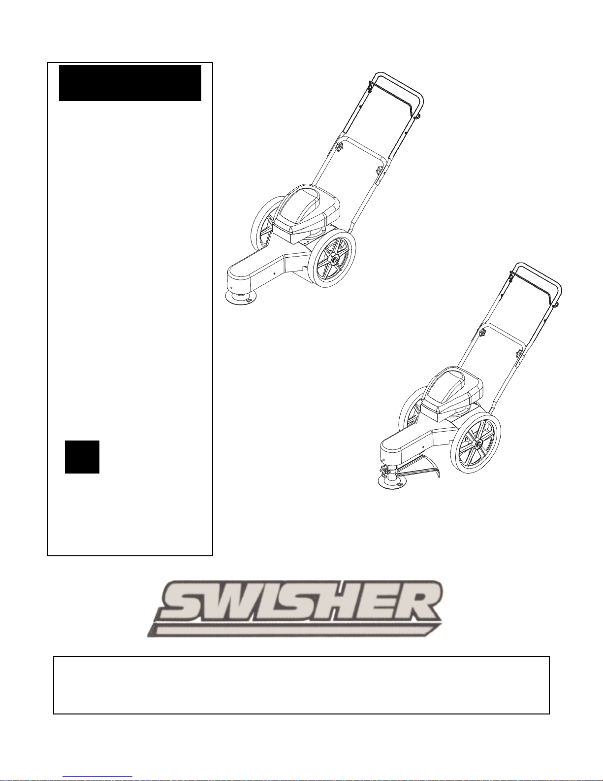
Trim-N-Mow
Trim-Max
Assembly
Operation
Service and Adjustment
1602 CORPORATE DRIVE, WARRENSBURG MISSOURI 64093
Manufacturing quality lawn care equipment since 1945
10698 REV 11-255
Repair Parts
PHONE 660-747-8183 FAX 660-747-8650
Made In The
USA

LIMITED WARRANTY
The manufacturer’s warranty to the original consumer purchaser is: This product is free from defects in
materials and workmanship for a period of two (2) years from the date of purchase by the original consumer
purchaser. We will repair or replace, at our discretion, parts found to be defective due to materials or
workmanship. This warranty is subject to the following limitations and exclusions:
1) Engine Warranty All engines utilized on our products have a separate warranty extended
to them by the individual engine manufacturer. Any engine service
difficulty is the responsibility of the engine manufacturer and in no way
is Swisher or its agents responsible for the engine warranty. The Briggs
& Stratton Engine Service Hot-Line is 1-800-233-3723. The Tecumseh
Engine Service Hot-Line is 1-800-558-5402.
2) Commercial Use This product is not intended for commercial use and carries no
commercial warranty.
3) Limitation This warranty applies only to products which have been properly
assembled, adjusted, and operated in accordance with the instructions
contained within this manual. This warranty does not apply to any
product of Swisher that has been subject to alteration, misuse, abuse,
improper assembly or installation, shipping damage, or to normal wear
of the product.
4) Exclusions Excluded from this warranty are normal wear, normal adjustments, and
normal maintenance.
In the event you have a claim under this warranty, you must return the product to an authorized service
dealer. All transportation charges, damage, or loss incurred during transportation of parts submitted for
replacement or repair under this warranty shall be borne by the purchaser. Should you have any questions
concerning this warranty, please contact us toll-free at 1-800-222-8183. The model number, serial number,
date of purchase, and the name of the authorized Swisher dealer from whom you purchased the mower will
be needed before any warranty claim can be processed.
THIS WARRANTY DOES NOT APPLY TO ANY INCIDENTAL OR CONSEQUENTIAL DAMAGES
AND ANY IMPLIED WARRANTIES ARE LIMITED TO THE SAME TIME PERIODS STATED
HEREIN FOR ALL EXPRESSED WARRANTIES. Some states do not allow the limitation of
consequential damages or limitations on how long an implied warranty may last, so the above limitations or
exclusions may not apply to you. This warranty gives you specific legal rights and you may have other
rights, which vary from state-to-state. This is a limited warranty as defined by the Magnuson-Moss Act of
1975.
2

Read, understand and follow all instructions in the manual and on the trimmer
Stop the trimmer when crossing gravel drives, etc.
Safety Instructions
This Safety Alert Symbol indicates important messages in this
manual. When you see this symbol, carefully read the message that
follows and be alert to the possibility of personal injury.
•
before starting
•
Read this manual carefully. Become familiar with the controls and how to
operate the unit properly.
•
Only allow responsible adults, who are familiar with the instructions, to
operate the unit.
•
Clear the area of objects such as rocks, toys, etc. that could be thrown by the
unit.
•
Be sure the area is clear of other people before trimming. Stop the unit if
anyone enters the area.
•
Be aware of the direction of the trimmer discharge and do not direct it at
anyone. Do not direct trimmer discharge at breakable objects, such as
windows, etc.
•
Do not operate trimmer without all guards and shields in place.
•
Never leave the machine running unattended.
•
Trim only in daylight or good artificial light.
•
Do not operate the trimmer while under the influence of alcohol or drugs.
•
Watch for traffic when operating near roadways.
•
Use the trimmer as the manufacturer intended and as described in the
manual.
•
Do not operate trimmer if it has been dropped or damaged in any manner.
Always have the damage repaired before operating.
•
Always wear safety glasses or eye shields when using the trimmer.
•
Dress properly. Do not operate the trimmer when barefoot or wearing open
sandals. Wear only solid shoes for good traction when trimming. Wear long
sleeved shirts or jackets, also long pants. Do not trim in shorts.
•
Keep your eyes and mind on your trimmer and the area being trimmed.
•
Do not let other interests distract you.
•
Do not put hands and feet near or under rotating parts.
•
Before cleaning, inspecting or repairing your trimmer, stop the engine and
disconnect the spark plug wire and keep it away from the spark plug to
prevent accidental starting.
•
Do not operate the trimmer if it vibrates abnormally. Excessive vibration is a
sign of damage. Stop the engine and safely check for damage and repair as
required.
•
Do not operate the trimmer in wet grass, where good footing may not be
possible. Walk; never run
•
3

Slope Operation
Use extra care when approaching blind corners, shrubs, trees or other objects
that may obstruct vision.
Slopes are a major factor related to loss of control and slip accidents,
which can result in severe injury. All slopes require extra caution. If you
feel uneasy on it do not trim it.
•
DO: Trim across the face of a slope and not up and down.
•
DO: Remove objects such as rocks, tree limbs, etc.
•
DO: Watch for holes, ruts or bumps. Tall grass can hide obstacles.
•
DO NOT: Mow near drop-offs, ditches or embankments. The operator could
loose footing or balance.
•
DO NOT: Trim excessively steep slopes
•
DO NOT: Trim on wet grass. Reduced footing could cause slipping.
Children
•
Keep children out of the area and under the watchful care of another
responsible adult.
•
Be alert and turn the machine off if children enter the area.
•
Before and when backing, look behind and down for small children.
•
Never allow children to operate this machine.
•
• Use extra care handling gasoline and other fuels. They are flammable and
vapors are explosive.
• Use only an approved container.
• Never remove gas cap or add fuel with the engine running.
• Allow engine to cool before refueling. Do not smoke while refueling
• Never refuel the machine indoors.
• Never store the machine or fuel container where there is an open flame, such
as a water heater.
• Never run a machine inside a closed area.
• Keep nuts and bolts tight and equipment in good condition.
• Never tamper with safety devices.
• Keep machine free of grass, leaves or other debris build up. Clean oil or fuel
spillage. Allow machine to cool before storing.
• Stop and inspect the equipment if you strike an object. Repair if necessary
before restarting.
• Never make repairs or adjustments with the engine running.
Service
4

The operation of any cutter can encounter foreign objects to be thrown into the eyes, resulting in
severe eye damage. Always wear certified safety glasses or wide-vision safety goggles for over
spectacles before staring any cutting machine and while operating such a machine.
The operation of any cutter produces sound waves that are damaging to the human ear. Ear
protection is recommended.
CAUTION!
Tragic accidents can occur if the operator is not alert to the presence of children. Children
are often attracted to the machine and the mowing activity. Never assume that children
will remain where you last saw them.
Do not operate the trimmer if it vibrates abnormally. Excessive vibration is a sign of
Damage. Stop the engine and safely check for damage and repair as required
Trimmer Head
Instruction Decal
OD68
Caution Notice Decal
OD67
Trim-Max Decal
OD64
Trim-N-Mow Decal
OD65
5
Assembly
Contents of Box:
• Trimmer
• Parts bag containing:
• Manual
• Engine manual
• Safety goggles
• Bottle of engine oil
• 2 sets of .155 trimmer line
• Cable Clip
Tools Required:
• ½” wrench
Installation of handles:
• Remove loose fasteners from lower handles.
• Pivot handles up and align lower hole in handles with hole on trimmer frame. Install
hardware removed in previous step. Snug, but do not tighten bolts.
• Pivot upper handles to fit the lower handles. Tighten knobs.
• Adjust handles for comfortable operation.
• Tighten all bolts.
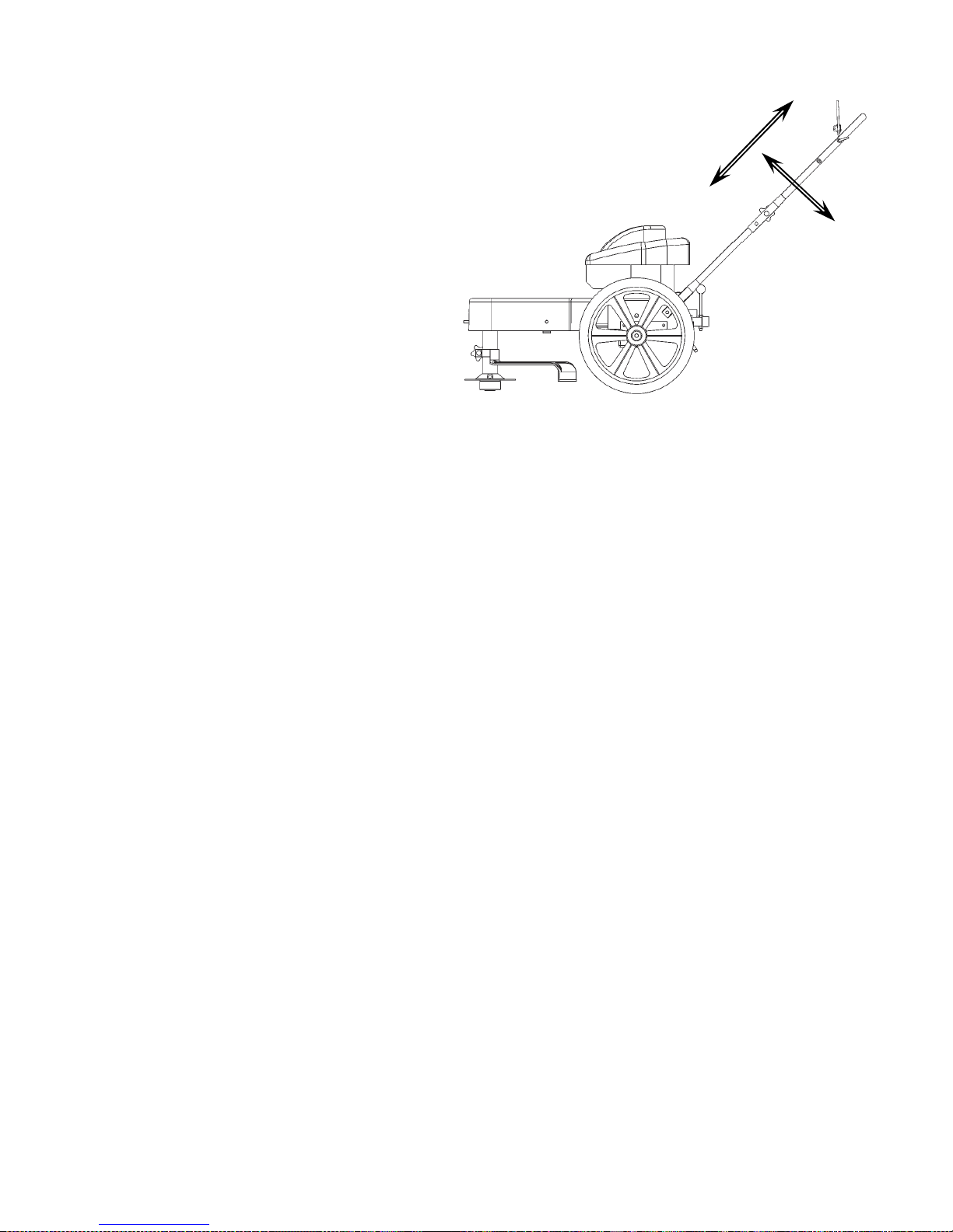
Handle Adjustment
Handles may be adjusted up and down and in and out for comfortable operation.
Installation Of Wheels
Refer to Page 12 for illustration.
• Slide axle through the mounting plates.
• Install Conical springs with the large diameter side against the Axle Plate.
• Install Spring Retainer against the conical spring.
• Slip wheel on one side and install Cotter Pin.
• Bend cotter pin over to prevent it from falling out.
• Push the Axle completely over to the other side.
• Install the second wheel and insert cotter pin and bend. Some compression of the
conical springs is necessary .
6

Preparing Unit For First Use
• Fill engine crankcase with oil. A bottle has been provided with this unit. DO
NOT OVERFILL.
• Fill the engine fuel tank with gasoline. GASOLINE SHOULD BE ADDED
OUTSIDE IN A WELL-VENTILATED AREA.
• Check to ensure string has been installed properly. A diagram is provided just
above the wheel for proper installation.
Operation
Important! To ensure proper operation, clean the engine and trimmer
regularly. Remove any build up of chaff from the top of the engine.
To stop the trimmer:
To stop the trimmer:
• Release the control bail. Engine will stop immediately
• Release the control bail. Engine will stop immediately
To start the trimmer:
To start the trimmer:
• Remove any built up debris from engine.
• Remove any built up debris from engine.
• Pull control bail against the handle and hold.
• Pull control bail against the handle and hold.
• Push primer button on engine as directed.
• Push primer button on engine as directed.
• Pull back sharply on recoil starter handle.
• Pull back sharply on recoil starter handle.
• Begin trimming.
• Begin trimming.
Important! For safest operation, make sure debris is directed away from you and others.
Important! For safest operation, make sure debris is directed away from you and others.
Important! On 12 Volt Start units. For optimum battery performance, you should run engine
Important! On 12 Volt Start units. For optimum battery performance, you should run engine
for at least 15 Minutes after start to keep battery charged.
for at least 15 Minutes after start to keep battery charged.
Trimming Hints
• Do not lift the trimmer head when trimming. Let the head rest lightly touching the ground.
• Keep an eye on the length of the trimmer line. As the line gets shorter they become less
effective at cutting and will take longer to trim properly. Replace the line as necessary. (See
installing cutter line).
• Do not trim wet grass.
• Use caution when trimming slopes.
• Use the proper length on line. Using a line too long for the unit will cause stalling and
unacceptable operation.
Troubleshooting
• If engine will not start, remove and check air filter to make sure filter and
carburetor are clean.
7
Installing Trimmer Line
Important! Use the proper length of line. Using a line too long for the unit will cause
stalling and unacceptable operation.
5+ HP use 18” String
Pre Cut Line Purchase P3618
• Loosely fold cutter line in half.
Step 1
Step 2 Step 3
• (1) Place loop of line against outside of loop on the trimmer head.
• (2) Bring ends around and through the loop and over the cutter line loop.
• (3) Pull ends to tighten loop.
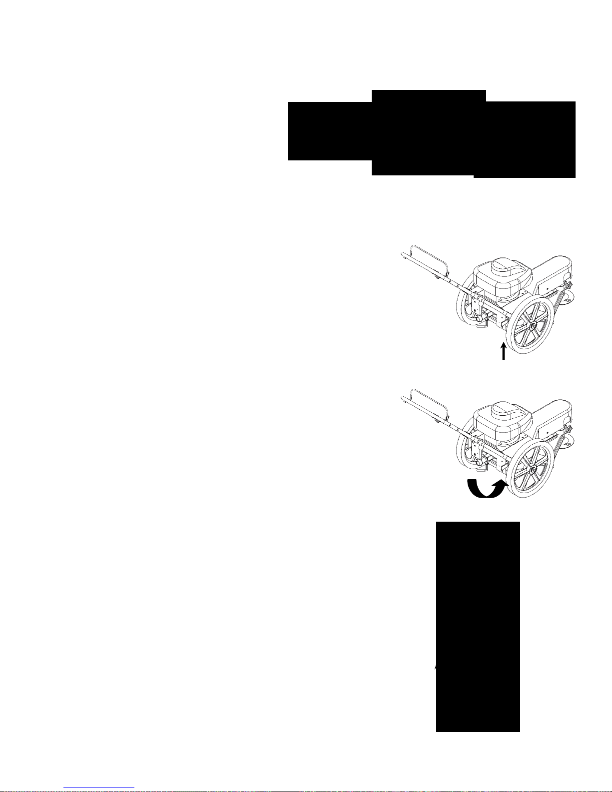
Trim-Max Operation
The Trim-Max trimmer is designed to also be used as an edge trimmer and to offset left
to right for easier close trimming.
Edge trimming/ Bevel Cutting
The trimmer disk may be tilted from horizontal to vertical so that it may be used as an
edge trimmer. The head may also be tilted slightly to trim closer. This may be handy for
trimming foundations without damaging the siding.
To Tilt:
• Stop unit.
•
Make sure head is in the straight forward position. (see offset operation)
• Loosen the trimmer tilt clamp lever. (Clockwise)
• Tilt head to desired position.
•
Tighten trimmer tilt clamp lever. (Counter Clockwise)
• Adjust Lower trimmer shield to keep debris from coming back at operator.
Offset trimming.
The trimmer head may be offset to the left or right to allow trimming under bushes, etc.
To Offset:
•
Stop unit.
• Raise offset lever.
•
Push or pull handles to achieve desired offset.
• Release offset lever. Make sure head has locked into position.
•
Adjust lower trimmer shield to keep debris from coming back at operator.
Important! Note direction of debris when offsetting head.
Offsetting trimmer to the left is recommended.
Trim-Max Pivot Adjustment
Trim-Max Tilt Adjustment
Direction Of Debris
8

Make sure your trimmer is in safe w orking condition by keeping the following guidelines in mind
Keep trimmer in good operating condition and keep all guards and shields in place. DO N OT
Check all fasteners for secure fit to keep equipment in safe working order. M ake adjustments
or m issing muffler. DO N OT tamper with exhaust
Trimmer Maintenance
every time you use your trim mer.
•
operate this trim mer if any of the shields and guards are missing.
•
as necessary.
•
To reduce fire hazards, keep engine free of grass leaves or excessive grease.
•
DO N OT operate trim mer with a damaged
system; this may cause a fire hazard.
• DO N OT operate engine if air cleaner or the cover over the carburetor air intake is missing.
Removal of these parts could create a fire hazard.
• Before cleaning, m aking adjustments or repairing the trimm er, STOP engine, disconnect
spark plug w ire and allow engine to cool.
•
Handle G asoline with care. DO NO T smoke or use open flame near gasoline. Use only
approved gasoline containers. Never fuel or run trim mer in poorly ventilated areas, such as a
garage or utility building.
•
Always replace fuel tank cap. Be sure to clean up any spilled gasoline.
• Do not change the engine governor settings or over-speed the engine; severe injury or
damage m ay result.
•
Never store mower, with gasoline in the tank, inside a building w here fumes m ay reach an
open flame or spark. Alw ays allow engine to cool before storing
NEVER ADD GASOLINE TO A HOT ENGINE – ALLOW ENGINE TO
CO O L BEFORE ADDING GASOLINE
WARNING – ALWAYS STOP ENGINE AND DISCONNECT SPARK PLUG
WIRE BEFORE PERFORMING ANY ADJUSTMENTS OR SERVICE
Engine
• Refer to the engine service manual provided with this unit.
Belt
• Occasionally check the belt for wear. A worn belt should be replaced.
Belt Adjustment
• The TRIM-N-MOW has an automatic belt tightener and needs no further adjustment
• The TRIM-MAX has an automatic belt tightener that automatically adjusts when the head is tilted. If
you do not regularly tilt the head on your trimmer, it is recommended that you loosen the head twice a
year. (See edge trimming)
Belt Replacement
• Remove front belt cover.
• Push trimmer head toward back of unit, compressing tensioner spring.
• Remove old belt.
• Install new belt by first routing belt under the engine and around the engine pulley.
• Push trimmer head toward back of unit, compressing tensioner spring.
• Install belt over front pulley.
• Release trimmer head. Ensure that belt is correctly installed in the groove of the engine and front
pulleys.
Re install front belt Cover.
9

Trim-N-Mow
(Standard)
Paint Reference Chart
Color Paint Code
Texture Black TK
Texture Red TC
Item # Description Part # Item # Description Part #
1 Briggs & Stratton Engine N/A 16 Operator Presence Bail 10397
2 Trimmer Pulley & Washer 2065 17 3/16 X 1 Key Stock 9030
3 5/16-18 X 3/4 Serr Flg Bolt NB596 18 Cotter Pin NB126
4 SP Washer Bellvile NB607 19 Conical Spring 10004
5 Rear Cover 2026 20 Washer NB275
6 Belt Guard 2019 21 5/16-18 x 3/4 Self Tapping Screw 26X249
7 Blade Belt 2113 22 Operator Presence Cable 2034B
8 Rubber Shield 2027 23 3/8-24 X 1 Engine Bolt Locktite NB238N
9 Lower Motor Base 2006 24 5/16-18 X 2 Carriage Bolt NB587
10 5/16-18 X 1 1/4 Flange Bolt NB253 25 5/16-18 X 2 1/4 Flange Bolt NB622
11 5/16-18 Serrated Flange Nut NB170 26 14" Wheel 2002
12 Upper Motor Base 2005 27 Axle 14416
13 Lower Handle 10399TK 28 Spring Retainer T2PB
14 Black Plastic Knob 2030 29 Washer NB177
15 Upper Handle 10578TK
10
 Loading...