

Page 1
Parts QTY PARTS QTY
MCWRES-1000 reservoir 1 MCP350 12 Volts Pump, with RPM sensor 1
5 ¼” Rack 1 Worm-drive clamps 2
M3x6mm Philips screws 4 Fill-cap and O-ring 1
Preamble
In the context of a first time liquid cooling circuit installation, the MCRES-1000 should be the last component to be
installed.
The radiator inlet and outlet spigots must be oriented upwards during the filling procedure.
Physically disconnect the computer from the A/C power source while filing up the circuit. Disconnect the
motherboard from the power supply, and remove all unnecessary components such as CD-Rom and hard drive(s).
Proceed deliberately and frequently check your work. Rushing this procedure is not recommended
Two methods can be used to fill-up the reservoir:
Preferred (Chapter I): whenever possible, the reservoir should be filled before placing it in the CD-Rom bay.
Alternate (Chapter II): If your chassis configuration necessitates that the reservoir be installed in the CD-Rom bay
prior to filling, please refer to chapter II “Alternate Filling Procedure
.
”.
I. FIRST TIME INSTALLATION AND PREFERRED FILLING PROCEDURE
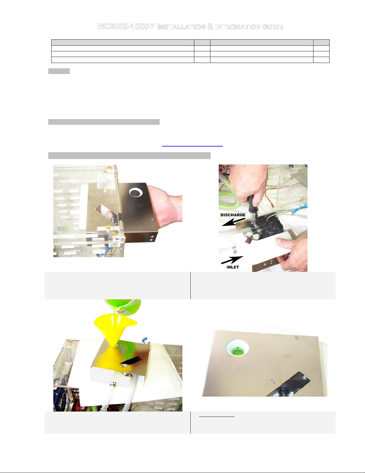
Step 1. Cutting the tubes to length: position the MCRES-1000 in
the desired CD-Rom drive bay, and cut sufficient length of tubing
in order to allow the assembly to slide back as shown above for
periodic maintenance purposes.
Step 3. Rest the MCRES-1000P assembly on a paper towel or
cloth on top of the computer. Using a household funnel, fill-up the
reservoir with cooling fluid - slowly to avoid overflowing, until
the fluid reaches the appropriate level --------------
Step 2. Connect the discharge tube to the pump (coming from
either CPU inlet, or radiator for example), and the return line to
the reservoir inlet barb. Secure the tubes with the provided
worm-drive clamps. Tighten quite firmly, but not excessively as it
may result in crushing the plastic barbs.
3. Appropriate level: up to the vent hole.
Copyright Swiftech 2005 – All rights reserved – Last revision date: 4-16-05 - Information subject to change without notice – URL: http://www.swiftnets.com
Rouchon Industries, Inc., dba Swiftech – 1703 E. 28th Street, Signal Hill, CA 90755 – Tel. 562-595-8009 – Fax 562-595-8769 - E Mail: Swiftech@swiftnets.com PAGE 1 of 4
Page 2

TIP! If you overfill the reservoir, you can use a bundled-up
paper towel to soak-up the excess fluid.
Step 4. Tilt the assembly upwards to allow the fluid to fill-up the
circuit by simple gravity. Allow the fluid to fill-up both tubes. The
pump discharge line will retain a 2” long bubble, which is
normal at this stage. See troubleshooting note (1) if the pump
discharge tube does not fill-up properly.
Step 5. Rest the assembly back on top of the computer, and
complete filling-up the reservoir until the fluid reaches the
appropriate level. Close the fill port with the provided fill-cap. Do
not over tighten the fill-cap. The fill-cap is equipped with an oring and does not require excessive pressure to seal properly.
Step 6. Rest the assembly on its side, down on your workbench
and connect the pump Molex connector to the power supply. You
must be able to start the PSU without it being connected to the
motherboard (See Note 2). Start-up the PSU. The pump has a 3
Seconds delay before it start running. Observe the flow circulating
throughout the circuit, until all the bubbles disappear. DO NOT
OPERATE THE PUMP IF THERE IS NO CIRCULATION, and
refer to troubleshooting note (1) before proceeding any further.
ALLOW THE SYSTEM TO RUN FOR (3) HOURS, AND FREQUENTLY INSPECT ALL YOUR CONNECTIONS FOR POSSIBLE LEAKS.
Step 7. Rest the assembly back on top of the computer, and
complete filling-up the reservoir as necessary. You may slightly
angle (approx. 15°) the reservoir to top-off the fluid level, by
placing a small object under the reservoir. Then close the fill port
with the provided fill-cap. Your reservoir is now ready to use.
Step 9. Connect the pump’s 4 pin Molex connector to the computer PSU, and the 3-pin connector (RPM sensor) to the CPU fan
header on the motherboard. INSTALLATION IS NOW COMPLETE!
Step 8. Install the assembly in the desired CR Rom bay, and
secure with the provided standard M3 screws. The MCRES1000P is designed to be recessed from the front panel, and allow
clearance for various cover plates or fan controllers.
Copyright Swiftech 2005 – All rights reserved – Last revision date: 4-16-05 - Information subject to change without notice – URL: http://www.swiftnets.com
Rouchon Industries, Inc., dba Swiftech – 1703 E. 28th Street, Signal Hill, CA 90755 – Tel. 562-595-8009 – Fax 562-595-8769 - E Mail: Swiftech@swiftnets.com PAGE 2 of 4
Page 3

II. ALTERNATE FILLING PROCEDURE
The following filling procedure applies to situations where the reservoir must be or is already installed inside of the CD-Rom
bay. Please refer to steps 1, and 2 in chapter I for physical connections and installation in the CD-Rom drive Bay.
Step 1. Radiator inlet and outlet should always be oriented
upwards during the filling procedure. In the above picture, the
MCB-120 Radbox conveniently allows you to let the radiator fan
assembly hang from your workbench.
Step 3. Fill-up the reservoir to the appropriate level (see step 3
chapter I, page 1). Proceed slowly and inspect level frequently
to avoid overflowing.
Step 5. Connect the pump 4-pin Molex connector to the powersupply, and then lay down the PC flat on the workbench. You
must be able to start the PSU without it being connected to the
motherboard (See Note 2, chapter III, page 4).
What to expect: when you start-up the power-supply, you will
hear a low and continuous hum indicating that the pump is
working, then a sudden gurgling as the mix of fluid and air start
rushing into the pump. Then the gurgling will gradually disappears
as all the air is being flushed out.
Action! Start-up the PSU. Wait 5 to 10 seconds until you see the
fluid circulate, or hear it gurgling. If nothing happens, shutdown
and restart the pump once or twice, letting the pump run a
maximum of 5 to 10 seconds in between each shutdown. Once
the pump has primed and the liquid circulates, let the pump run
for another 5 minutes to allow all the air to be flushed out from the
circuit.
IF THERE IS NO FLUID CIRCULATION, DO NOT OPERATE
THE PUMP, and refer to troubleshooting note (1) chapter III,
page 4 before you proceed any further.
Step 2. Stuff a cloth or towel behind the MCRES-1000 to prevent
liquid from dripping over components in case of an accidental
spill, and then set the front of the PC on an object so that the
chassis will be at a 15 to 20° angle from horizontal.
Step 4. Close the fill port with the provided fill-cap.
Copyright Swiftech 2005 – All rights reserved – Last revision date: 4-16-05 - Information subject to change without notice – URL: http://www.swiftnets.com
Rouchon Industries, Inc., dba Swiftech – 1703 E. 28th Street, Signal Hill, CA 90755 – Tel. 562-595-8009 – Fax 562-595-8769 - E Mail: Swiftech@swiftnets.com PAGE 3 of 4
Page 4

Step 6. Bring the PC back up as shown in step 3 above (keep it angled at 15 to 20°), and complete filling-up the reservoir as
necessary, and then close the fill port.
Your system is now ready to use! Complete the installation by securing the MCRES-1000 in the CD-Rom bay with the provided M3
screws, as shown in step 8, chapter I page 2.
ALLOW THE SYSTEM TO RUN FOR (3) HOURS, AND FREQUENTLY INSPECT ALL YOUR CONNECTIONS FOR POSSIBLE
LEAKS PRIOR TO RECONNECTING MOTHERBOARD AND OTHER ELECTRONIC COMPONENTS
III. NOTES AND TROUBLESHOOTING
Note (1) – Troubleshooting
While filling up the reservoir, the pump discharge tube does not fill-up with fluid: this will prevent the pump from priming
and circulate the liquid thru the circuit. It means that there is a significant pocket of air trapped in the circuit, preventing the fluid to
rise up to the pump discharge spigot. Make sure that your reservoir inlet and outlet barbs are oriented upwards. If your installation
required that the reservoir be mounted upside-down, temporarily dismount it from the chassis, this will allow the air to escape and
travel up to the reservoir. If you are using Swiftech’s “Radbox” simply remove the 4 screws from the half shell and rotate the
reservoir until the filling procedure is complete, then re-attach the radiator/fan/half shell assembly to the Radbox base.
Air keeps circulating into the circuit, long after the pump has primed:
Note (2) - Starting the Power Supply when the motherboard is not connected
While the Internet contains numerous references on how to use a paper-clip to short-out pin 13 and 14 of the 20 pin ATX connector as
shown below, we nonetheless recommend instead using a power-supply tester. A wide variety of these common devices are available
on the Internet (Google key word: “PSU tester”), and among Swiftech resellers (www.frozencpu.com, www.Directron.com,
www.newegg.com, etc.).
o There is a significant pocket of air trapped into the circuit, check the radiator as indicated above, and/or the water-block.
o The fluid level is too low: top-off the reservoir to the appropriate level.
o One of the components connections is loose, or improperly tightened: Inspect each connection for traces of moisture,
and tighten all worm-drive clamps, and various connections in the circuit.
13
14
IV. MCP350 Pump Specifications
General Use
The MCP350™ pump is a magnetically driven centrifugal pump featuring a 12 V DC brushless motor. It requires no maintenance when
used with de-mineralized water and the appropriate anti-fungal additives. We recommend using 5% Swiftech’s HydrX as an additive.
The pump is designed to be connected to your computer power supply using the standard Molex 4 pin connectors. The pump features a
second connector (3-pin type) with only 1 wire. It is designed to connect to the motherboard CPU fan header, and to report the impeller
rotational speed (RPM sensor). Set your BIOS to monitor the CPU fan, and this will shut down the PC in case of pump failure.
Pump operating precautions
The MCP350™ pump should never be run dry, even for a quick test. You should always prime the pump with fluid before you start
operating it (see warranty note *). With filled lines, turn the inlet/outlets upward to ensure there is no air bubble in the impeller.
Use of coloring die or fluorescent additives containing particulate fillers will cause excessive wear to the pump’s impeller bearing (see
warranty note **).
Nominal voltage: 12 V DC Operating voltage range: 9 to 13.2 VDC
Nominal power (@ 12 V): 8.3 W Nominal current (@ 12 V): .69 amps
Motor type Electronically commutated, brushless DC, spherical motor
Nominal head (@ 12 V): 13.05 ft (4 m) Nominal discharge (@ 12 V): ~ 92.4 GPH (350 LPH)
Connection size: 3/8" barbs (10mm) Maximum pressure: 22 PSI (1.5 BAR)
Temperature range: Up to 140°F (60°C) MTBF (Mean Time Between Failures): 50,000 Hours
Electrical connector: Molex 4 pin RPM sensor: 3-pin connector
Weight: 7.3 oz (207 gr.) 7.3 oz (207 gr.)
Our noise measurement (non lab environment) 24 ~ 26 dBA in a quiet room @ 2'
IMPORTANT DISCLOSURES While all efforts have been made to provide the most comprehensive tutorial possible, Swiftech assumes
no liability expressed or implied for any damage(s) occurring to your components as a result of using Swiftech cooling products, either due
to mistake or omission on our part in the above instructions, or due to failure or defect in the Swiftech cooling products. WARRANTY Our
products are guaranteed for 12 months from the date of delivery to the final user against defects in materials or workmanship. During this
period, they will be repaired or have parts replaced provided that: (I) the product is returned to the agent from which it was purchased; (II)
the product has been purchased by the end user and not used for hire purposes; (III) the product has not been misused, handled
carelessly, or other than in accordance with any instructions provided with respect to its use. This guarantee does not confer rights other
than those expressly set out above and does not cover any claims for consequential loss or damage. This guarantee is offered as an extra
benefit and does not affect your statutory rights as a consumer.
Copyright Swiftech 2005 – All rights reserved – Last revision date: 4-16-05 - Information subject to change without notice – URL: http://www.swiftnets.com
Rouchon Industries, Inc., dba Swiftech – 1703 E. 28th Street, Signal Hill, CA 90755 – Tel. 562-595-8009 – Fax 562-595-8769 - E Mail: Swiftech@swiftnets.com PAGE 4 of 4
 Loading...