


H20 220

These instructions are updated on a regular basis. Please visit our web site at www.swifte ch.com
Copyright Swiftech 2008 – All rights reserved – Last revision date: 10-29-08- Information subject to change without notice – URL: http://www.swiftech.com
Rouchon Industries, Inc., dba Swiftech – 3700 Industry Avenue, Suite 104, CA 90712 – Tel. 562-595-8009 – Fax 562-595-8769 - E Mail: help@swiftech.com
1 of 17
Packing List
QTY ITEM
APOGEE GTZ water-block, including socket 775 and socket
1
1366 hold-down plates for Intel Core® (Core 2, Duo, Quad,
Extreme, i7) series of micro-processors.
Important note: Free Upgrade available (see terms and
conditions) for AMD® socket 754, 939, and AM2, as well as
Intel® socket 771 (Xeon series) Server form factor
MCP655-B pump, including mounting hardware and (2) ½” hose
1
clamps
MCRES-Micro Rev. 2, including ½” hose-barb fittings, and hose
1
clamps, bracketry & hardware for various installation: 1 “L”
bracket, 2 “U” brackets
MCR220 Radiator assembly, including (2) pre-installed 120mm
1
fans with fan guards, mounting hardware, ½” black nylon hose
barb fittings, (2) 12v to 7v adapters, (2) 12v to 5v 3-pin to 4-pin
Molex adapters, and (2) hose clamps
And Pre-installed MCB-120 Radbox, with mounting hardware
Feet 7/16” industrial grade PVC tubing
8
Length (40”) Smartcoils 625 blue
1
2 Oz. Bottle of HydrX concentrated coolant
1
Syringe of Arctic Céramique thermal compound
1
Warning!
The Apogee GTZ water-block included with your kit is compatible with all the most popular
processors available on the market. In an effort to cut on waste however, some of the less popular
mounting mechanisms
demand. They are:
• Hold-down plate for Intel® legacy server platforms (socket 771, Xeon)
• Hold-down plate for AMD® socket 754, 939, F and AM2
If you own one of the above platforms, all you have to do is contact customer support and the part
will be shipped to you at no charge by express mail or equivalent. The following terms and
conditions apply:
Worldwide except Europe:
Please email within 90 days of your date of purchase (proof of purchase required), call, write or Fax
to Swiftech customer service at:
Europe: Please email
required)
have not been physically included in the kit and are available for free on
TOLL FREE (Continental US only)
1-888-85SWIFT (1-888-857-9438)
Mailing
Address
Swiftech
3700 Industry Ave., suite
104
Lakewood, CA 90712
USA
Telephone (562) 595-8009
Fax (562) 595-8769
rma@bacata.net within 90 days of your date of purchase (proof of purchase
Copyright Swiftech 2008 – All rights reserved – Last revision date: 10-29-08- Information subject to change without notice – URL: http://www.swiftech.com
Rouchon Industries, Inc., dba Swiftech – 3700 Industry Avenue, Suite 104, CA 90712 – Tel. 562-595-8009 – Fax 562-595-8769 - E Mail: help@swiftech.com
2 of 17

TTAABBLLEE OOFF CCOONNTTEENNTTSS
I. PLANNING............................................................................................................................................. 4
1. General Guidelines................................................................................................................................. 4
2. Tube Routing .......................................................................................................................................... 4
II. INSTALLATION OF THE COOLING COMPONENTS.......................................................................... 5
1. MCR220 Radiator installation................................................................................................................ 6
General concept schematic............................................................................................................. 6
Installation........................................................................................................................................ 7
2. APOGEE GTZ Water-block installation................................................................................................ 8
Installation with Intel® socket 775, Core™ 2, Core Duo, Extreme (default water-block configuration)
8
Installation with Intel® socket 1366, Core™ i7 Desktop Solutions - Removal of the default hold-
down plate required................................................................................................................................ 9
Installation with Intel® socket 1366 (Core™ i7) Server Solutions................................................. 10
Installation with Intel® legacy server platforms (socket 771, Xeon).............................................. 10
Installation with AMD® socket 754, 939, F and AM2.................................................................... 10
3. Re-installing the motherboard ............................................................................................................ 10
4. Pump installation.................................................................................................................................. 11
General Use................................................................................................................................... 11
Physical installation........................................................................................................................ 11
Pump operating precautions:......................................................................................................... 11
5. MCRES-Micro reservoir Installation................................................................................................... 12
Installation...................................................................................................................................... 13
Preparing the coolant..................................................................................................................... 14
6. Installing the tubing ............................................................................................................................. 15
7. Completing the installation ................................................................................................................. 15
Re-installing your power-supply..................................................................................................... 15
Filling-up the circuit........................................................................................................................ 16
8. Troubleshooting................................................................................................................................... 17
9. Draining the system............................................................................................................................. 17
10. Periodic Maintenance........................................................................................................................... 17
11. Optional Components.......................................................................................................................... 17
Copyright Swiftech 2008 – All rights reserved – Last revision date: 10-29-08- Information subject to change without notice – URL: http://www.swiftech.com
Rouchon Industries, Inc., dba Swiftech – 3700 Industry Avenue, Suite 104, CA 90712 – Tel. 562-595-8009 – Fax 562-595-8769 - E Mail: help@swiftech.com
3 of 17

INTRODUCTION
Congratulations on your purchase of a Swiftech™ H20-APEX liquid cooling system!
This kit has been designed to facilitate the installation of the components with a minimum of case modifications.
While all attempts have been made to make the installation of this system user friendly, please note that this system
is intended for users that are well versed in installing computer components.
While all efforts have been made to provide the most comprehensive tutorial possible, Swiftech assumes no liability expressed or implied for
any damage(s) occurring to your components as a result of using Swiftech cooling products, either due to mistake or omission on our part in
the above instructions, or due to failure or defect in the Swiftech™ cooling products.
In addition, Swiftech assumes no liability, expressed or implied, for the use of this product, and more specifically for any, and all damages
caused by the use of this product to any other device in a personal computer, whether due to product failure, leak, electrical short, and or
electro-magnetic emissions.
Our products are guaranteed for 12 months from the date of delivery to the final user against defects in materials or workmanship. During this
period, they will be repaired or have parts replaced provided that: (I) the product is returned to the agent from which it was purchased; (II) the
product has been purchased by the end user and not used for hire purposes; (III) the product has not been misused, handled carel essly, or
other than in accordance with any instructions provided with respect to its use. This guarantee does not confer rights other than those expressly
set out above and does not cover any claims for consequential loss or damage. This guarantee is offered as an extra benefit and does not
affect your statutory rights as a consumer.
DISCLAIMER
WARRANTY
I. Planning
1. GENERAL GUIDELINES
Please read this guide carefully and entirely before you start this installation. Plan your installation ahead. Observe the
relative position of the components for possible interference with other components.
Never work with electricity connected to the computer while work is in progress.
Because some work is necessary that will require cutting holes in the case, it is strongly recommended to remove all the
components from the case prior to begin with this installation.
After the metal work has been completed, carefully clean the case to remove all metal debris.
Once the time has come to re-install the motherboard and complete the liquid-cooling circ uit, the motherboard should be
disconnected from the power-supply at all times during the entire mock-up phase of the installation. In case of a spill or leak
on the motherboard, do not panic! As long as the motherboard is not electrically connected, no harm is done. You must
however thoroughly dry the exposed area, using a hair dryer for e xample, and wait a minimum of 6 to 8 hours prior to reconnecting the motherboard to its power source.
The reservoir should preferably be installed at the highest point of the cooling circuit (top 5 ¼” tray), although this is not
absolutely necessary if all the other components are self-purging.
Think about the airflow inside your chassis. In liquid-cooling environments, it is always better to draw fresh air from the
outside through the radiator, as opposed to using the warm air from inside the computer.
Make sure to dry-fit all components before making final connections and filling the water-cooling system.
2. TUBE ROUTING
The tubing for the water-cooling system must be routed to form a complete loop that includes all elements of the system.
When daisy-chaining components, the simplest and most natural route is usually the best. Always avoid sharp bends that
would kink the tubing!
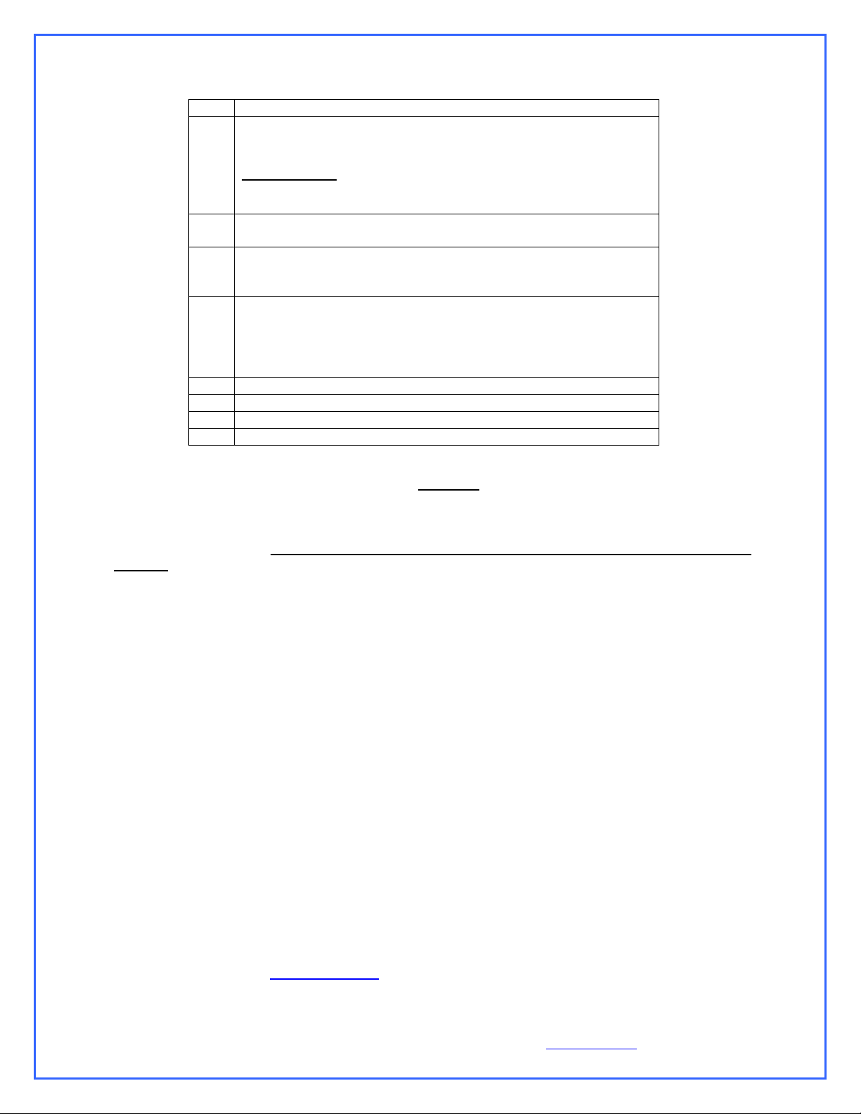
The following table contains examples on how to establish connections between the different elements of a cooling circuit
based on multiple possible configurations. These are guidelines only, and may change depending on the relative position of
the components inside your chassis.
Copyright Swiftech 2008 – All rights reserved – Last revision date: 10-29-08- Information subject to change without notice – URL: http://www.swiftech.com
Rouchon Industries, Inc., dba Swiftech – 3700 Industry Avenue, Suite 104, CA 90712 – Tel. 562-595-8009 – Fax 562-595-8769 - E Mail: help@swiftech.com
4 of 17

From a performance standpoint there is very little performance to be gained from strictly controlling the component
sequence: the maximum delta T (difference in temperature) between any two points of the liquid cooling circuit does not
exceed 1ºC. Whenever possible, performance oriented users will typically want to route the radiator discharge(s) tube(s) to
the inlet of the CPU cooler, since the fluid exiting the radiators is always the coolest.
Devices: (1) CPU cooler + (1) Radiator + Pump-reservoir assembly
Connect: Pump discharge to radiator inlet
Alternatively,
Connect Pump discharge to CPU cooler inlet
Devices (1) CPU cooler + (1) VGA cooler + (1) Radiator + Pump-reservoir assembly
Connect: Pump discharge to VGA Cooler inlet
Alternatively,
Connect: Pump discharge to CPU cooler inlet
Devices: (1) CPU cooler + (1) VGA Cooler + (1) chipset Cooler + (1) Radiator + Pump-reservoir assembly
Connect: Pump discharge to chipset cooler inlet
Alternatively,
Connect: Pump discharge to CPU cooler inlet
Devices: Dual CPU cooler and VGA cooler (SLI) configurations
Connect: CPU coolers in series: CPU cooler (1) discharge to CPU cooler (2) inlet
Devices: Dual Radiators: A second radiator can be added anywhere in the loop in series with the other components,
Connect Pump discharge to radiator (1) inlet
Radiator discharge to CPU cooler inlet
CPU cooler discharge to reservoir inlet
Reservoir discharge to pump inlet – MANDATORY!
CPU cooler discharge to radiator inlet
Radiator discharge to reservoir inlet
Reservoir discharge to pump inlet – MANDATORY!
VGA cooler discharge to radiator inlet
Radiator discharge to CPU cooler inlet
CPU cooler discharge to reservoir inlet
Reservoir discharge to pump inlet – MANDATORY!
CPU cooler discharge to VGA cooler inlet
VGA cooler discharge to radiator inlet
Radiator discharge to reservoir inlet
Reservoir discharge to pump inlet – MANDATORY!
Chipset cooler discharge to VGA cooler inlet
VGA cooler discharge to radiator inlet
Radiator discharge to CPU cooler inlet
CPU cooler discharge to reservoir inlet
Reservoir discharge to pump inlet – MANDATORY!
CPU cooler discharge to chipset cooler inlet
Chipset cooler discharge to VGA cooler inlet
VGA cooler discharge to radiator inlet
Radiator discharge to reservoir inlet
Reservoir discharge to pump inlet – MANDATORY!
VGA coolers in series: VGA cooler (1) discharge to VGA cooler (2) inlet
for example
Radiator (1) discharge to VGA cooler inlet
VGA Cooler discharge to chipset cooler inlet
Chipset cooler discharge to radiator (2) inlet
Radiator (2) discharge to CPU cooler inlet
CPU cooler discharge to reservoir inlet
Reservoir discharge to pump inlet – MANDATORY!
II. Installation of the cooling components
Warning! Placement of the cooling components may vary depending on your chassis and motherboard configurations. A mock-up
installation is thus necessary to estimate the length of the different sections of tubing that will be required between each component.
The following is the recommended sequence of components installation.
1. Radiator and fan
2. Water-block(s)
3. Pump
4. Reservoir
Copyright Swiftech 2008 – All rights reserved – Last revision date: 10-29-08- Information subject to change without notice – URL: http://www.swiftech.com
Rouchon Industries, Inc., dba Swiftech – 3700 Industry Avenue, Suite 104, CA 90712 – Tel. 562-595-8009 – Fax 562-595-8769 - E Mail: help@swiftech.com
5 of 17

1. MCR220 RADIATOR INSTALLATION
Preamble:
The MCR220™ dual 120mm radiator ships with the fans and the Radbox chassis already pre-assembled to the radiat or. It is assumed in effect
that users will take advantage of our Radbox concept (external radiator installation) due to the ben efits it provides and ease of installation. In
such context, the following installation guide describes this type of installation. We also recognize that due to various considerations (cosmetics,
space, or simply user preference) a number of users will wish to install the MR220 radiator internally. Because of the large size of the radiator, it
is most likely that an internal installation will require extensive modifications in most computer cases. Because these modifications depend on the
structure and dimensions of each individual chassis, we simply cannot provide precise installation instructions to this effect. Here are some
general guidelines that advanced “case-modders” should take into consideration:
Radiator installation, general considerations:
For optimum performance radiators require an unobstructed source of cool air. This dictates either an external mounting or one on/in the case
where the radiator will draw cool air from the exterior. The second consideration is the placement of the inlet and outlet connections; at least one
connection should be at the ‘top’ of the radiator to make it self-purging.
An external mounting can be effectuated by means of the RadBox affixed to the backside of the case and the tubing routed through holes drilled
in the case underneath the power-supply. This places the connections at the top of the radiator and it will preclude the accumulation of air in the
radiator.
Single 120mm fan radiators can be mounted over appropriately sized openings in a variety of cases; conversely, mounting a dual 120mm
radiator is considerably more difficult and generally results in placing the radiator ‘inverted’ at the top, or ‘right side up’ at the bottom. Note that
the ‘inverted’ mounting places the inlet and outlet facing down; this mounting will accumulate air over time. Placing the radiator ‘right side up’ in
the case bottom will make the radiator self-purging, but it will gather dust VERY quickly if adjacent to the floor. In many situations, mounting a
dual 120mm radiator inside a case will require extensive modifications for the air inlet and mounting of the radiator; it should be noted m that
case manufacturer growing awareness for water-cooling fosters the release of “liquid-cooling ready“ solutions that will greatly facilitate the
installation of this kit. There is no standard in this respect, and therefore no “formula” for installation; as a result users will simply need to exercise
common sense and good judgment.
General concept schematic
Copyright Swiftech 2008 – All rights reserved – Last revision date: 10-29-08- Information subject to change without notice – URL: http://www.swiftech.com
Rouchon Industries, Inc., dba Swiftech – 3700 Industry Avenue, Suite 104, CA 90712 – Tel. 562-595-8009 – Fax 562-595-8769 - E Mail: help@swiftech.com
6 of 17
 Loading...