

Page 1

These instructions are updated on a regular basis. Please visit our web site at
http://www.swiftnets.com
Copyright Swiftech 2005 – All rights reserved – Last revision date: 12-27-05 - Information subject to change without notice – URL: http://www.swiftnets.com
Rouchon Industries, Inc., dba Swiftech – 1703 E. 28
th
Street, Signal Hill, CA 90755 – Tel. 562-595-8009 – Fax 562-595-8769 - E Mail: Swiftech@swiftnets.com PAGE 1 of 32
Page 2

Included components check-marked per applicable model:
H20-220-PT □ H20-220-775T □ H20-220-64T □ H20-220-AT □
Description Product
Intel Pentium 4 (socket 478)
Intel Pentium 4 (LGA775)
Product
Qty Item Product
Code
PT 1 MCW5002-PT thermoelectric water-
block, with (2) # 6 worm drive hose
clamps & gaskets
775T 1 MCW5002-775T thermoelectric water-
block with (2) # 6 worm drive hose
clamps & gaskets
64T 1 MCW5002-64T thermoelectric water-
block with (2) # 6 worm drive hose
clamps & gaskets
AT 1 MCW5002-AT thermoelectric water-
block with (2) # 6 worm drive hose
clamps & gaskets
ALL 1 MCR220-QPK Radiator with
120x25mm fan and Radbox
Packing List
Code
PT
775T
Code
ALL 1
ALL 1 MCRES-MICRO Reservoir with retention
ALL 1
ALL 1 10 Feet 7/16” ID High quality vinyl tubing
ALL 1
Description Product
AMDAthlon 64 (SOCKET 754, 939, 940)
AMDAthlon MP, XP (socket 462)
Qty Item
MCP655 12 Volts DC industrial pump with
retention screws and hose clamps
screws , Velcro strips and hose clamps
40” length smatcoils clear coils
2 oz bottle HydrX specially formulated
coolant
Code
64T
AT
ALL 1 Luberex Dielectric grease
ALL 1 S320-12 Kit, 25 Amps auxiliary power
supply with relay switch harness
ALL 1
ALL 1 MG chemicals conformal coating spray
Céramique thermal grease
Copyright Swiftech 2005 – All rights reserved – Last revision date: 12-27-05 - Information subject to change without notice – URL: http://www.swiftnets.com
Rouchon Industries, Inc., dba Swiftech – 1703 E. 28
th
Street, Signal Hill, CA 90755 – Tel. 562-595-8009 – Fax 562-595-8769 - E Mail: Swiftech@swiftnets.com PAGE 2 of 32
Page 3

TABLE OF CONTENTS
I. Motherboard preparation & water-block mechanical installation ............................................................................................6
1. MCW5002-775T™ Thermoelectric Water-block Installation Guide for Intel Pentium 4 (LGA775)....................................7
A. Preparing the motherboard......................................................................................................................................................7
B. Condensation control measures .............................................................................................................................................. 7
C. Motherboard preparation ........................................................................................................................................................ 8
D. CPU preparation and water-block installation ........................................................................................................................8
E. Hydraulic Installation .............................................................................................................................................................9
2. MCW5002-PT™ Thermoelectric Water-block Installation Guide for Intel Pentium 4 (socket 478).................................10
A. Preparing the Motherboard ...................................................................................................................................................10
B. Condensation control measures ............................................................................................................................................ 11
C. Motherboard preparation ...................................................................................................................................................... 11
D. CPU and water-block installation .........................................................................................................................................12
E. Hydraulic Installation ...........................................................................................................................................................12
3. MCW5002-AT™ Thermoelectric Waterblock Installation Guide for AMD Athlon MP, XP, Sempron (socket 462
motherboards with mounting holes exclusively).................................................................................................................................13
A. Condensation control measures: Motherboard preparation .................................................................................................. 13
B. CPU and water-block installation ........................................................................................................................................14
C. Hydraulic Installation ...........................................................................................................................................................15
4. MCW5002-64T™ Thermoelectric Water-block Installation Guide for AMD Athlon 64, Opteron (socket 754, 939, 940).....16
A. Condensation prevention measures: Motherboard preparation ............................................................................................. 16
B. CPU and cooler installation ..................................................................................................................................................17
C. Hydraulic Installation ...........................................................................................................................................................18
II. Components (other than water-block) installation....................................................................................................................19
1. S320-12 power supply kit installation guide..............................................................................................................................19
A. S320-12 Power supply installation .......................................................................................................................................19
B. Relay Switch Installation ......................................................................................................................................................20
C. Power Supply ventilation...................................................................................................................................................... 21
2. MCR220 Radiator installation ..................................................................................................................................................23
A. Radiator installation, general considerations ........................................................................................................................23
B. Installation with the Radbox .................................................................................................................................................23
C. Securing the base plate at the desired location...................................................................................................................... 24
D. Fastening the radiator/Radbox assembly to the computer back-panel.................................................................................. 24
3. Re-installing the motherboard/water-block assembly into the chassis......................................................................................26
4. MCP655 Pump Installation.......................................................................................................................................................27
A. General Use ..........................................................................................................................................................................27
B. Installation ............................................................................................................................................................................27
C. Precautions............................................................................................................................................................................27
5. MCRES-Micro reservoir Installation........................................................................................................................................29
A. Installation ............................................................................................................................................................................29
B. Fastening the device to the case ............................................................................................................................................ 29
6. Tubing installation.....................................................................................................................................................................30
A. Preamble: difficult installation of the tubing with the MCP655 pump .................................................................................30
B. Preparing the coolant ............................................................................................................................................................30
C. Precautions of use with the MCRES-Micro reservoir........................................................................................................... 30
D. Pre-cutting the tubing to length and tube routing..................................................................................................................30
E. Re-installing your computer power-supply...........................................................................................................................31
F. Filling-up the circuit .............................................................................................................................................................31
G. Post-installation note: Draining the system...........................................................................................................................31
7. Electrical connection: TEC to S320-12 power-supply ..............................................................................................................31
Copyright Swiftech 2005 – All rights reserved – Last revision date: 12-27-05 - Information subject to change without notice – URL: http://www.swiftnets.com
Rouchon Industries, Inc., dba Swiftech – 1703 E. 28
th
Street, Signal Hill, CA 90755 – Tel. 562-595-8009 – Fax 562-595-8769 - E Mail: Swiftech@swiftnets.com PAGE 3 of 32
Page 4

III. Periodic maintenance...................................................................................................................................................................32
A. Keeping your system clean ...................................................................................................................................................32
B. Fluid Level............................................................................................................................................................................ 32
C. Draining the system ..............................................................................................................................................................32
Copyright Swiftech 2005 – All rights reserved – Last revision date: 12-27-05 - Information subject to change without notice – URL: http://www.swiftnets.com
Rouchon Industries, Inc., dba Swiftech – 1703 E. 28
th
Street, Signal Hill, CA 90755 – Tel. 562-595-8009 – Fax 562-595-8769 - E Mail: Swiftech@swiftnets.com PAGE 4 of 32
Page 5

Preamble
Congratulations on your purchase of a Swiftech liquid cooling system!
This kit has been designed to facilitate the installation of the components with as few and simple modifications to the chassis as
possible. It is nonetheless intended for technically advanced users, well versed in installing computer components.
General guidelines
Never work with electricity connected to the computer while work is in progress.
The reservoir should preferably be at the highest point of the cooling circuit. This will allow air to accumulate there over time.
It is strongly recommended that you install this kit in a bare chassis, removing first all typical PC components such as motherboard,
power supply, hard drives, as well as side panels, front bezel, and top panel.
Plan your installation ahead. Observe the relative position of the components for possible interference with other components.
Examples: will the pump interfere with a hard drive? Will the radiator interfere with the installation of the CPU cooler?
Think about the airflow inside your chassis. In liquid-cooling environments, it is always better to draw fresh air from the outside
through the radiator, as opposed to using the warm air from inside the computer.
IMPORTANT DISCLOSURES
While all efforts have been made to provide the most comprehensive tutorial possible, Swiftech assumes no liability expressed or
implied for any damage(s) occurring to your components as a result of using Swiftech cooling products, either due to mistake or
omission on our part in the above instructions, or due to failure or defect in the Swiftech™ cooling products.
WARRANTY
Our products are guaranteed for 12 months from the date of delivery to the final user against defects in materials or workmanship.
During this period, they will be repaired or have parts replaced provided that: (I) the product is returned to the agent from which it
was purchased; (II) the product has been purchased by the end user and not used for hire purposes; (III) the product has not been
misused, handled carelessly, or other than in accordance with any instructions provided with respect to its use. This guarantee does
not confer rights other than those expressly set out above and does not cover any claims for consequential loss or damage. This
guarantee is offered as an extra benefit and does not affect your statutory rights as a consumer.
Copyright Swiftech 2005 – All rights reserved – Last revision date: 12-27-05 - Information subject to change without notice – URL: http://www.swiftnets.com
Rouchon Industries, Inc., dba Swiftech – 1703 E. 28
th
Street, Signal Hill, CA 90755 – Tel. 562-595-8009 – Fax 562-595-8769 - E Mail: Swiftech@swiftnets.com PAGE 5 of 32
Page 6

Installation Overview
The following is a typical sequence of components installation. Step 1 is always first. Steps 2 to 6 may be performed out of sequence
depending on the chassis configuration. Placement of the cooling components may also vary depending on your chassis and
motherboard configurations. A mock-up installation is thus necessary to estimate the length of the different sections of tubing that will
be required between each component.
STEP 1 Motherboard preparation, and Water-block(s)
Installation: Chapter 1
This part of the installation is by and large the most crucial and
should be done first. Please refer to your specific water-block
model in the water-block installation chapters below. It is
suggested that you complete steps 2 and 3 prior to re-installing
the motherboard/water-block assembly in the chassis.
STEP 2 Power Supply Installation: Chapter 2.1
The S320-12 auxiliary power supply supplied with your kit fits
in a 5 ¼” bay with the provided rails. Because it generates a
significant amount of heat, we recommend that it be installed in
the uppermost drive bay. To prevent it from overheating, a
blowhole in the upper panel located in the general vicinity of
the power supply exhaust vent is highly desirable. Guidelines
are also provided on how to make a blow hole.
Because this step may require case modifications, such as
drilling holes into the computer panels, please carefully cleanup the case for metal shavings.
STEP 3 Radiator installation: Chapter 2.2
The H20-220T kit is supplied with a dual 120mm radiator. The radiator is equipped with our MCB120 “Radbox” and should be
installed externally at the back of chassis. Because this step may require case modifications, such as drilling holes into the computer
panels, please carefully clean-up the case for metal shavings
STEP 4 Reinstall the motherboard/water-block assembly into the case: Chapter 2.3
STEP 5 MCP655 Pump installation: Chapter 2.4
Preferable position of the pump is at the bottom of the chassis.
However, the pump can operate in any position. For optimum
safety, the pump can be bolted to the chassis. TIP! Do not peeloff the protective sticker until you are satisfied with the position
of the pump, as subsequent removal is destructive to the foam
gasket.
STEP 6 MCRES-MICRO reservoir installation: Chapter 2.5
This reservoir being the simplest to install, it is suggested that
you install it last.
TIP! Positioning the reservoir at the highest point of the liquid
cooling circuit is preferred but not mandatory. If one of the
components, the radiator for example, is higher than the
reservoir, you may want to fill-up the reservoir outside of the
chassis, holding it above the radiator, and once done close the
fill-cap, and secure the reservoir in the desired bay.
STEP 7 and forward refer to hydraulic and electrical connections and finishing of the installation: Chapter 2.6 to end
I. MOTHERBOARD PREPARATION & WATER-BLOCK MECHANICAL INSTALLATION
Please refer to the following chapters relevant to your model:
MCW5502-775T for Intel Pentium 4 socket LGA775
MCW5002-PT for Intel Pentium 4 socket 478
MCW5002-AT for AMD socket 462
MCW5002-64T for AMD socket 754, 939, 940
It is assumed below that you have removed the motherboard from the case.
Copyright Swiftech 2005 – All rights reserved – Last revision date: 12-27-05 - Information subject to change without notice – URL: http://www.swiftnets.com
Rouchon Industries, Inc., dba Swiftech – 1703 E. 28
th
Street, Signal Hill, CA 90755 – Tel. 562-595-8009 – Fax 562-595-8769 - E Mail: Swiftech@swiftnets.com PAGE 6 of 32
Page 7
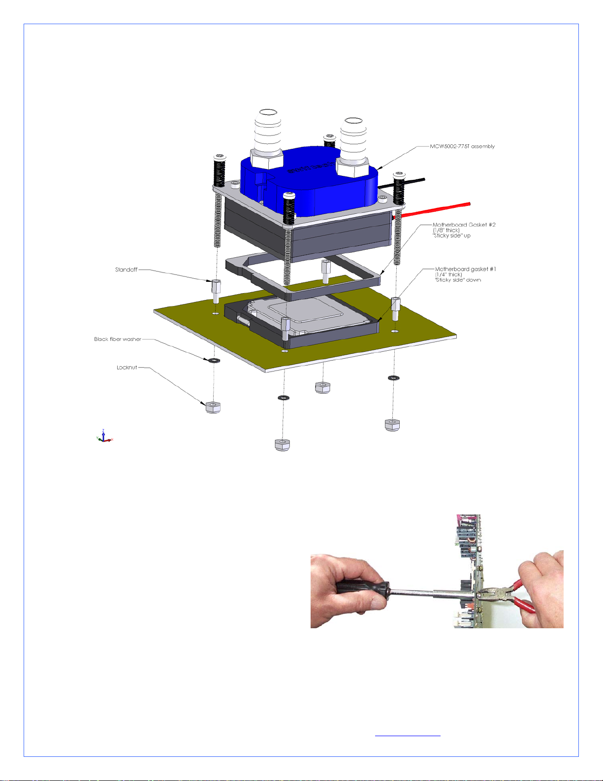
1. MCW5002-775T™ THERMOELECTRIC WATER-BLOCK INSTALLATION GUIDE FOR INTEL PENTIUM
4 (LGA775)
Figure 1
A. Preparing the motherboard
Remove the stock heatsink retention mechanism to reveal the
four-motherboard mounting holes.
Install a standoff in each one of the holes. As the diameter of
the mounting holes is usually larger than the diameter of the
standoff stem, be careful to keep the standoff approximately
centered in the MB holes. Secure the standoffs with the
provided hex locknuts, and a fiber washer on the backside of
the MB as shown on fig. 1, using the tools described fig. 2
Figure 2
Use a ¼” socket tool to drive the standoff, and a small pair of
pliers to prevent the locknut from spinning. Torque value should
not to exceed 16 in. lbs. In other words JUST FIRM AND
TIGHT, BUT WITHOUT EXCESSIVE TORQUE.
B. Condensation control measures
Copyright Swiftech 2005 – All rights reserved – Last revision date: 12-27-05 - Information subject to change without notice – URL: http://www.swiftnets.com
Rouchon Industries, Inc., dba Swiftech – 1703 E. 28
th
Street, Signal Hill, CA 90755 – Tel. 562-595-8009 – Fax 562-595-8769 - E Mail: Swiftech@swiftnets.com PAGE 7 of 32
Page 8

The following instructions are crucial to long lasting & reliable operations. Do not skip these steps, and do not take shortcuts.
Permanent damage to your components is likely to occur otherwise.
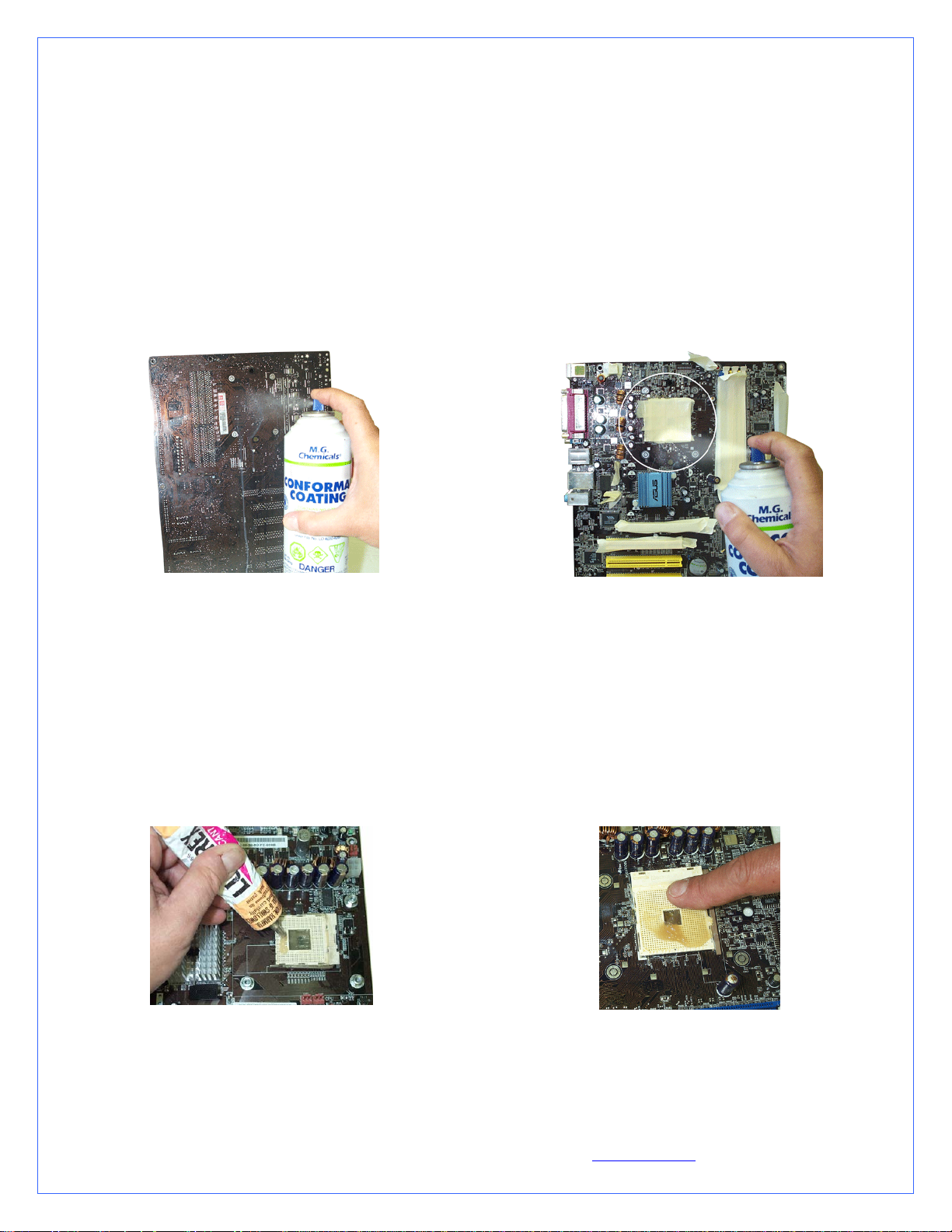
C. Motherboard preparation
Conformal coating application: This step will positively ensure that any micro condensation occurring on small surface mount
components will not corrode or short-circuit the motherboard. Please use the enclosed conformal coating spray.
Figure 3 - Back of the motherboard:
Figure 4 - Front of the motherboard
Spray the back of the motherboard, concentrating on the area
immediately behind the CPU. Also spray all the way down,
in a vertical path directly under the CPU area. Allow time to
dry, per manufacturer specs.
Use masking tape to protect the CPU socket, and any connector
sockets in the immediate vicinity of the processor. A double
layer of tape is recommended for all sockets, as the spray may
soak a single layer of tape and contaminate the contacts.
Spray the area immediately surrounding the socket. It is not
recommended to spray further than the area circled in the above
picture. Allow the coating to be “dry to the touch” (20 minutes
approximately), and remove the masking tape. Then let the
board dry completely per manufacturer specs.
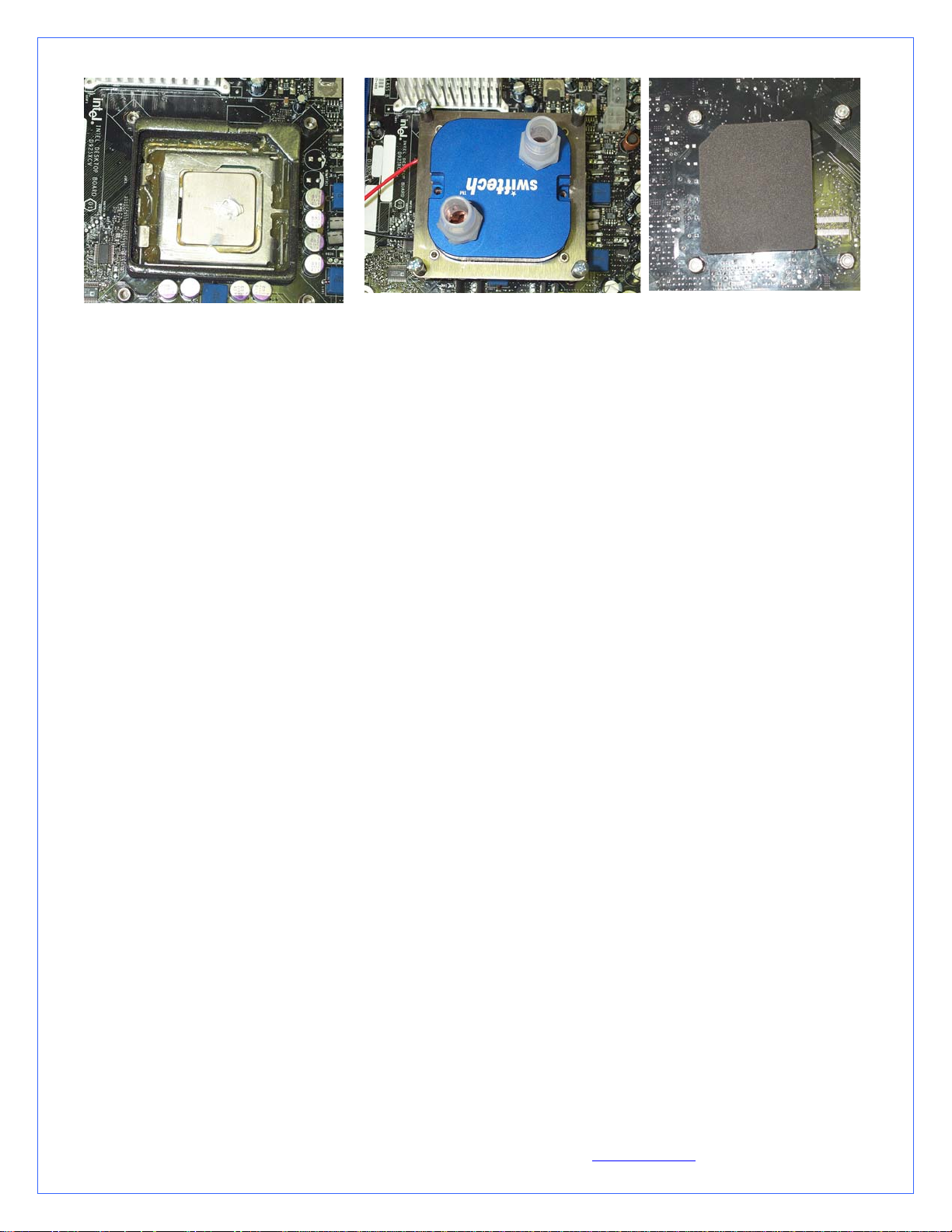
D. CPU preparation and water-block installation
Dielectric grease application: The following steps will ensure that condensation does not form inside of the CPU socket.
Please use the Luberex dielectric grease provided with your kit.
Step 1
1/ Install the motherboard gasket #1 (1/4”
thick)
2/ Squirt a generous amount of dielectric
grease inside the socket center section.
Step 2
3/ Place your CPU in the socket, and
gently push it down to pack the grease
inside the socket center section.
4/ squeeze more dielectric grease all
around, between the gasket and the CPU
socket
5/ Close the socket lever
6/ Clean off all the excess
grease, particularly on the CPU
itself. The surface of the CPU
needs to be clean for the next
step which is application of the
thermal grease.
Copyright Swiftech 2005 – All rights reserved – Last revision date: 12-27-05 - Information subject to change without notice – URL: http://www.swiftnets.com
Rouchon Industries, Inc., dba Swiftech – 1703 E. 28
th
Street, Signal Hill, CA 90755 – Tel. 562-595-8009 – Fax 562-595-8769 - E Mail: Swiftech@swiftnets.com PAGE 8 of 32
Step 3
Page 9
Step 4
7/ Squeeze a small amount of Céramique
thermal compound on the CPU.
8/ Peel-off the protective paper from
motherboard gasket #2 (1/8” thick) and
carefully align the gasket over
motherboard gasket #1, with the sticky
side up
Step 5
9/ Align the water-block mounting posts
with the motherboard standoffs, and
tighten the screws in a cross pattern. Do
not over-tighten the screws or they could
jam into the standoffs, making further
removal difficult.
The water-block is now installed
10/ There will be grease
squeezing off from the holes
behind the motherboard. Wipe it
out clean.
11/ Stick the neoprene gasket
directly behind the CPU (use
the center section of
motherboard gasket #1). This
Step 6
will prevent condensation to
form here over time.
IMPORTANT WARNING: Solder joints of the wires to the thermoelectric module are extremely fragile. Bending the wires at their
root will break the solder joint, with no possible repair. Swiftech will not honor the warranty for broken wires.
E. Hydraulic Installation
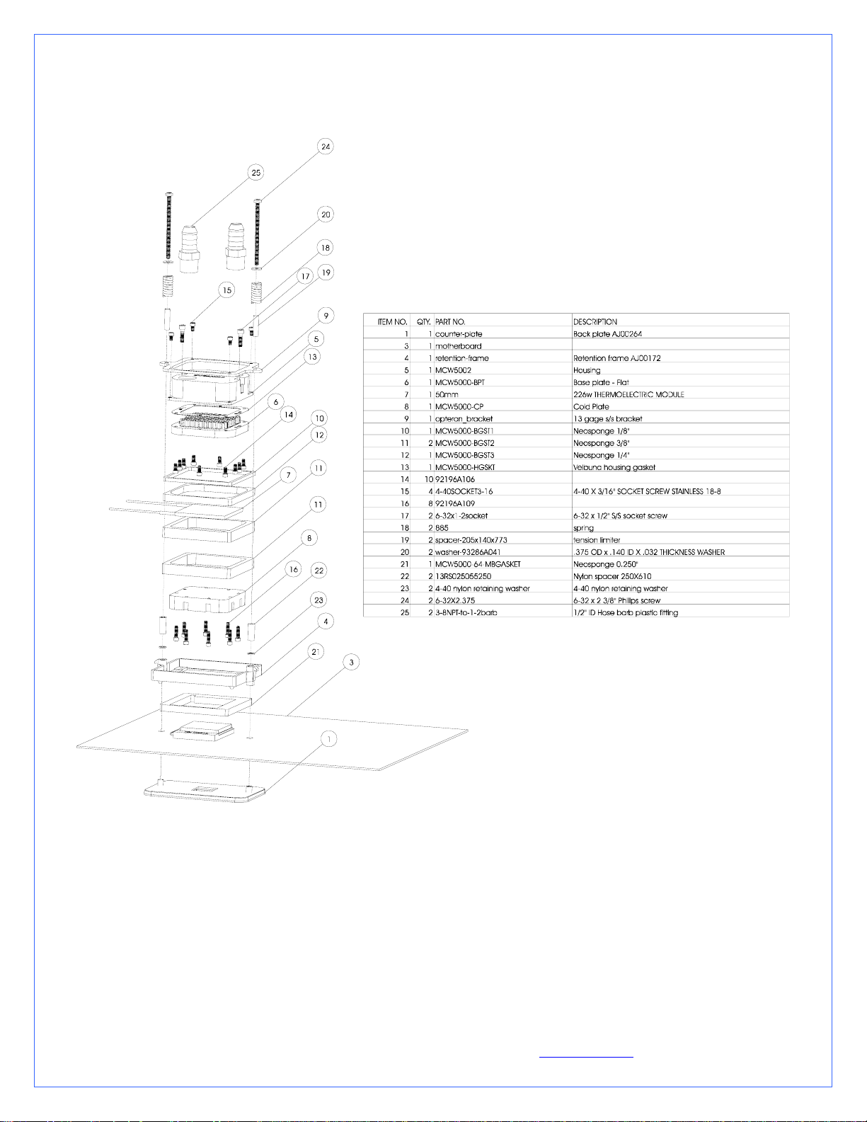
The MCW5002-T is shipped with ½” barb to 3/8” NPT nylon fittings. These fittings should be installed using
Teflon tape or plumbers “goop”. If fittings need to be replaced for a difference tubing size, do not use brass fittings,
because of the galvanic corrosion that will take place between copper or brass and the MCW5002-T aluminum
housing. Always use nylon fittings.
Inlet and outlet are interchangeable.
Type of Coolant:
For best performance, use 5 to 10% of Swiftech brand “HydrX” corrosion inhibitor mixed with distilled
water only .
Regular automotive anti-freeze is also acceptable. Automotive manufacturers recommend that not less than
25% is used.
NEVER use tap water, even for a short-term test.
Not following the above instructions constitutes misuse (*) of the product, and will void your warranty.
Now that the water-block installation is complete, please proceed with the rest of the components installation as described in Chapter
II.
Copyright Swiftech 2005 – All rights reserved – Last revision date: 12-27-05 - Information subject to change without notice – URL: http://www.swiftnets.com
Rouchon Industries, Inc., dba Swiftech – 1703 E. 28
th
Street, Signal Hill, CA 90755 – Tel. 562-595-8009 – Fax 562-595-8769 - E Mail: Swiftech@swiftnets.com PAGE 9 of 32
Page 10

2. MCW5002-PT™ THERMOELECTRIC WATER-BLOCK INSTALLATION GUIDE FOR INTEL PENTIUM 4
(SOCKET 478)
Figure 1
A. Preparing the Motherboard
Remove the stock heatsink retention frame (the black plastic
frame that clips down to your motherboard). This will reveal
the four mounting holes used to install the MCW5000-PT
retention standoffs.
Install a standoff in each one of the holes. As the diameter of
the mounting holes is much larger than the diameter of the
standoff stem, be careful to keep the standoff approximately
centered in the MB holes. Secure standoffs with hex locknuts,
and a fiber washer on backside of the MB as shown on fig. 1,
Figure 2
using the tools described fig. 2
Copyright Swiftech 2005 – All rights reserved – Last revision date: 12-27-05 - Information subject to change without notice – URL: http://www.swiftnets.com
Rouchon Industries, Inc., dba Swiftech – 1703 E. 28
th
Street, Signal Hill, CA 90755 – Tel. 562-595-8009 – Fax 562-595-8769 - E Mail: Swiftech@swiftnets.com PAGE 10 of 32
Page 11
Use a ¼” socket tool to drive the standoff, and a small pair of
pliers to prevent the locknut from spinning. Torque value should
not to exceed 16 in. lbs. In other words JUST TIGHT,
WITHOUT EXCESSIVE TORQUE.
B. Condensation control measures
The following instructions are crucial to long lasting & reliable operations. Do not skip these steps, and do not take shortcuts.
Permanent damage to your components is likely to occur otherwise.
C. Motherboard preparation
Conformal coating application: This step will positively ensure that any micro condensation occurring on small surface mount
components will not corrode or short-circuit the motherboard. Please use the conformal coating spray included with the kit.
Figure 3
Spray the back of the motherboard, concentrating on the area
immediately behind the CPU. Also spray all the way down, in a
vertical path directly under the CPU area. Allow time to dry, per
manufacturer specs.
Figure 4
Use masking tape to protect the CPU socket, and any connector
sockets in the immediate vicinity of the processor. A double layer
of tape is recommended for all sockets, as the spray may soak a
single layer of tape and contaminate the contacts.
Spray the area immediately surrounding the socket. It is not
recommended to spray further than the area circled in the above
picture. Allow the coating to be “dry to the touch” (20 minutes
approximately), and remove the masking tape. Then let the board
dry completely per manufacturer specs.
Dielectric grease application: This step will ensure that condensation does not form inside of the CPU socket. Please use the
included Luberex dielectric grease as follows.
Figure 5
Figure 6
Squirt a generous amount of grease onto the socket. Force the grease inside of the pin-holes with your finger. Make
sure that the central area of the socket is completely filled with
grease.
Copyright Swiftech 2005 – All rights reserved – Last revision date: 12-27-05 - Information subject to change without notice – URL: http://www.swiftnets.com
Rouchon Industries, Inc., dba Swiftech – 1703 E. 28
th
Street, Signal Hill, CA 90755 – Tel. 562-595-8009 – Fax 562-595-8769 - E Mail: Swiftech@swiftnets.com PAGE 11 of 32
Page 12

To complete the condensation prevention measures, simply apply the neoprene sticker provided with your MCW5002-PT
accessories to the back of the motherboard, directly behind the processor.
D. CPU and water-block installation
Securing the MCW5002-PT cooler to the motherboard:
Install the MCW5002-PT assembly onto your processor, as shown in
figure 8.
Gradually tighten the screws in a cross pattern until you feel that they
reach the bottom of the standoff. A “finger-tight” lock is sufficient.
Figure 7
Remove the peel-off paper back from the motherboard
gasket, and install it as shown above. The sticky side should
be towards the motherboard.
Insert the processor into the socket. Since you have grease
inside the socket, some hydraulic pressure lift may occur:
for this reason, make sure that the processor sits perfectly
flat, and is inserted all the way into the socket.
Then, drop a small amount of high quality thermal
compound onto the center of the processor core.
Installation of the cooler to the motherboard is now
Figure 8 - (showing an MCW5000-PT)
complete!
IMPORTANT WARNING: Solder joints of the wires to the thermoelectric module are extremely fragile. Bending the wires at their
root will break the solder joint, with no possible repair. Swiftech will not honor the warranty for broken wires.
E. Hydraulic Installation
The MCW5002-T is shipped with ½” barb to 3/8” NPT nylon fittings. These fittings should be installed using
Teflon tape or plumbers “goop”. If fittings need to be replaced for a difference tubing size, do not use brass fittings,
because of the galvanic corrosion that will take place between copper or brass and the MCW5002-T aluminum
housing. Always use nylon fittings.
Inlet and outlet are interchangeable.
Type of Coolant:
For best performance, use 5 to 10% of Swiftech brand “HydrX” corrosion inhibitor mixed with distilled
water only .
Regular automotive anti-freeze is also acceptable. Automotive manufacturers recommend that not less than
25% is used.
NEVER use tap water, even for a short-term test.
Not following the above instructions constitutes misuse (*) of the product, and will void your warranty.
Now that the water-block installation is complete, please proceed with the rest of the components installation as described in Chapter
II.
.
Copyright Swiftech 2005 – All rights reserved – Last revision date: 12-27-05 - Information subject to change without notice – URL: http://www.swiftnets.com
Rouchon Industries, Inc., dba Swiftech – 1703 E. 28
th
Street, Signal Hill, CA 90755 – Tel. 562-595-8009 – Fax 562-595-8769 - E Mail: Swiftech@swiftnets.com PAGE 12 of 32
Page 13

3. MCW5002-AT™ THERMOELECTRIC WATERBLOCK INSTALLATION GUIDE FOR AMD ATHLON MP,
XP, SEMPRON (SOCKET 462 MOTHERBOARDS WITH MOUNTING HOLES EXCLUSIVELY)
Figure 1
Preamble
The following instructions are crucial to long lasting & reliable operations. Do not skip these steps, and do not take shortcuts.
Permanent damage to your components is likely to occur otherwise.
A. Condensation control measures: Motherboard preparation
Conformal coating application: This step will positively ensure that any micro condensation occurring on small surface mount
components will not corrode or short-circuit the motherboard. Please use the conformal coating spray included with the kit.
Copyright Swiftech 2005 – All rights reserved – Last revision date: 12-27-05 - Information subject to change without notice – URL: http://www.swiftnets.com
Rouchon Industries, Inc., dba Swiftech – 1703 E. 28
th
Street, Signal Hill, CA 90755 – Tel. 562-595-8009 – Fax 562-595-8769 - E Mail: Swiftech@swiftnets.com PAGE 13 of 32
Page 14

Figure 2
Spray the back of the motherboard, concentrating on the area
immediately behind the CPU. Also spray all the way down, in a
vertical path directly under the CPU area. Allow time to dry, per
manufacturer specs.
Use masking tape to protect the CPU socket, and any connector
sockets in the immediate vicinity of the processor. A double layer
of tape is recommended for all sockets, as the spray may soak a
single layer of tape and contaminate the contacts.
Figure 3
Spray the area immediately surrounding the socket. It is not
recommended to spray further than the area circled in the above
picture. Allow the coating to be “dry to the touch” (20 minutes
approximately), and remove the masking tape. Then let the board
dry completely per manufacturer specs.
Dielectric grease application: This step will ensure that condensation does not form inside of the CPU socket.
Figure 4
Figure 5
Squirt a generous amount of grease onto the socket. Force the grease inside of the pin-holes with your finger. Make
sure that the central area of the socket is completely filled with
grease.
B. CPU and water-block installation
Securing the MCW5002-AT cooler to the motherboard:
Initial check: make sure that the retention clips are at their lowest
position by tightening the 2 spring loaded Philips screws until the
springs are fully compressed (do not over-tighten)
Engage one side of the clip under the CPU socket retention lugs
Gently pull the water-block in the opposite direction and push it down
to catch the opposite set of socket lugs. The clip will snap underneath
the socket lugs.
Firmly press the base of the clips (through the gaskets) between middle
finger and thumb as shown in Figure 7 to compress them against the
Copyright Swiftech 2005 – All rights reserved – Last revision date: 12-27-05 - Information subject to change without notice – URL: http://www.swiftnets.com
Rouchon Industries, Inc., dba Swiftech – 1703 E. 28
th
Street, Signal Hill, CA 90755 – Tel. 562-595-8009 – Fax 562-595-8769 - E Mail: Swiftech@swiftnets.com PAGE 14 of 32
socket (this will prevent the clips for disengaging themselves from
Page 15

Figure 6
Remove the peel-off paper back from the motherboard
gasket, and install it as shown above. The sticky side should
be towards the motherboard.
Insert the processor into the socket. Since you have grease
inside the socket, some hydraulic pressure lift may occur:
for this reason, make sure that the processor sits perfectly
flat, and is inserted all the way into the socket.
Then, drop a small amount of high quality thermal
compound into the center of the processor core.
underneath the tabs at start-up) then gradually and alternatively loosen
the two spring loaded Philips screws to secure the water-block.
Continue backing off the screws until the head of each screw
completely clears the top of the bracket by about the thickness of a
credit card.
Figure 7
IMPORTANT WARNING: Solder joints of the wires to the thermoelectric module are extremely fragile. Bending the wires at their
root will break the solder joint, with no possible repair. Swiftech will not honor the warranty for broken wires.
C. Hydraulic Installation
The MCW5002-T is shipped with ½” barb to 3/8” NPT nylon fittings. These fittings should be installed using
Teflon tape or plumbers “goop”. If fittings need to be replaced for a difference tubing size, do not use brass fittings,
because of the galvanic corrosion that will take place between copper or brass and the MCW5002-T aluminum
housing. Always use nylon fittings.
Inlet and outlet are interchangeable.
Type of Coolant:
For best performance, use 5 to 10% of Swiftech brand “HydrX” corrosion inhibitor mixed with distilled
water only .
Regular automotive anti-freeze is also acceptable. Automotive manufacturers recommend that not less than
25% is used.
NEVER use tap water, even for a short-term test.
Not following the above instructions constitutes misuse (*) of the product, and will void your warranty.
Now that the water-block installation is complete, please proceed with the rest of the components installation as described in Chapter
II.
Copyright Swiftech 2005 – All rights reserved – Last revision date: 12-27-05 - Information subject to change without notice – URL: http://www.swiftnets.com
Rouchon Industries, Inc., dba Swiftech – 1703 E. 28
th
Street, Signal Hill, CA 90755 – Tel. 562-595-8009 – Fax 562-595-8769 - E Mail: Swiftech@swiftnets.com PAGE 15 of 32
Page 16
4. MCW5002-64T™ THERMOELECTRIC WATER-BLOCK INSTALLATION GUIDE FOR AMD ATHLON 64,
OPTERON (SOCKET 754, 939, 940)
Figure 1
Preamble
The following instructions are crucial to long lasting & reliable operations. Do not skip these steps, and do not take shortcuts.
Permanent damage to your components is likely to occur otherwise.
A. Condensation prevention measures: Motherboard preparation
Conformal coating application: This step will positively ensure that any micro condensation occurring on small surface mount
components will not corrode or short-circuit the motherboard. Please use the included conformal coating spray.
Copyright Swiftech 2005 – All rights reserved – Last revision date: 12-27-05 - Information subject to change without notice – URL: http://www.swiftnets.com
Rouchon Industries, Inc., dba Swiftech – 1703 E. 28
th
Street, Signal Hill, CA 90755 – Tel. 562-595-8009 – Fax 562-595-8769 - E Mail: Swiftech@swiftnets.com PAGE 16 of 32
Page 17
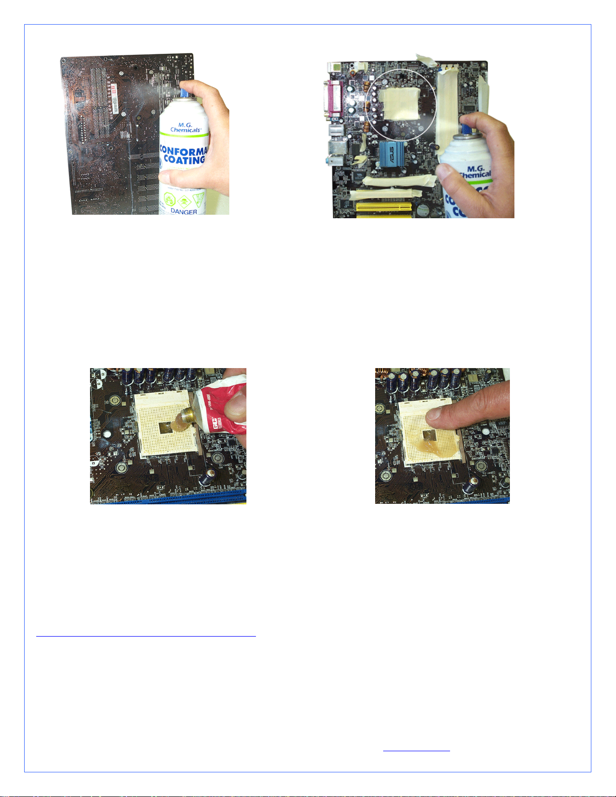
Figure 2
Spray the back of the motherboard, concentrating on
the area immediately behind the CPU. Also spray all
the way down, in a vertical path directly under the
CPU area. Allow time to dry, per manufacturer
specs.
Figure 3
Use masking tape to protect the CPU socket, and any connector sockets in
the immediate vicinity of the processor. A double layer of tape is
recommended for all sockets, as the spray may soak a single layer of tape and
contaminate the contacts.
Spray the area immediately surrounding the socket. It is not recommended to
spray further than the area circled in the above picture. Allow the coating to
be “dry to the touch” (20 minutes approximately), and remove the masking
tape. Then let the board dry completely per manufacturer specs.
Dielectric grease application: This step will ensure that condensation does not form inside of the CPU socket. Please use the
provided Luberex grease.
Figure 4
Figure 5
Squirt a generous amount of grease onto the socket. Force the grease inside of the pin holes with your finger. Make
sure that the central area of the socket is completely filled with
grease.
B. CPU and cooler installation
Preamble: The MCW5002-64T requires the AMD recommended motherboard backing plates (made out of metal) for its installation.
Some motherboard manufacturers use plastic back plates and snap-rivets to attach the CPU holding frame to the back-plate, which
cannot be used with the MCW5002-64T. AMD recommended backing plates and retention frames are available online on our site at:
http://www.swiftnets.com/store/category.asp?CatID=1
Copyright Swiftech 2005 – All rights reserved – Last revision date: 12-27-05 - Information subject to change without notice – URL: http://www.swiftnets.com
Rouchon Industries, Inc., dba Swiftech – 1703 E. 28
th
Street, Signal Hill, CA 90755 – Tel. 562-595-8009 – Fax 562-595-8769 - E Mail: Swiftech@swiftnets.com PAGE 17 of 32
Page 18
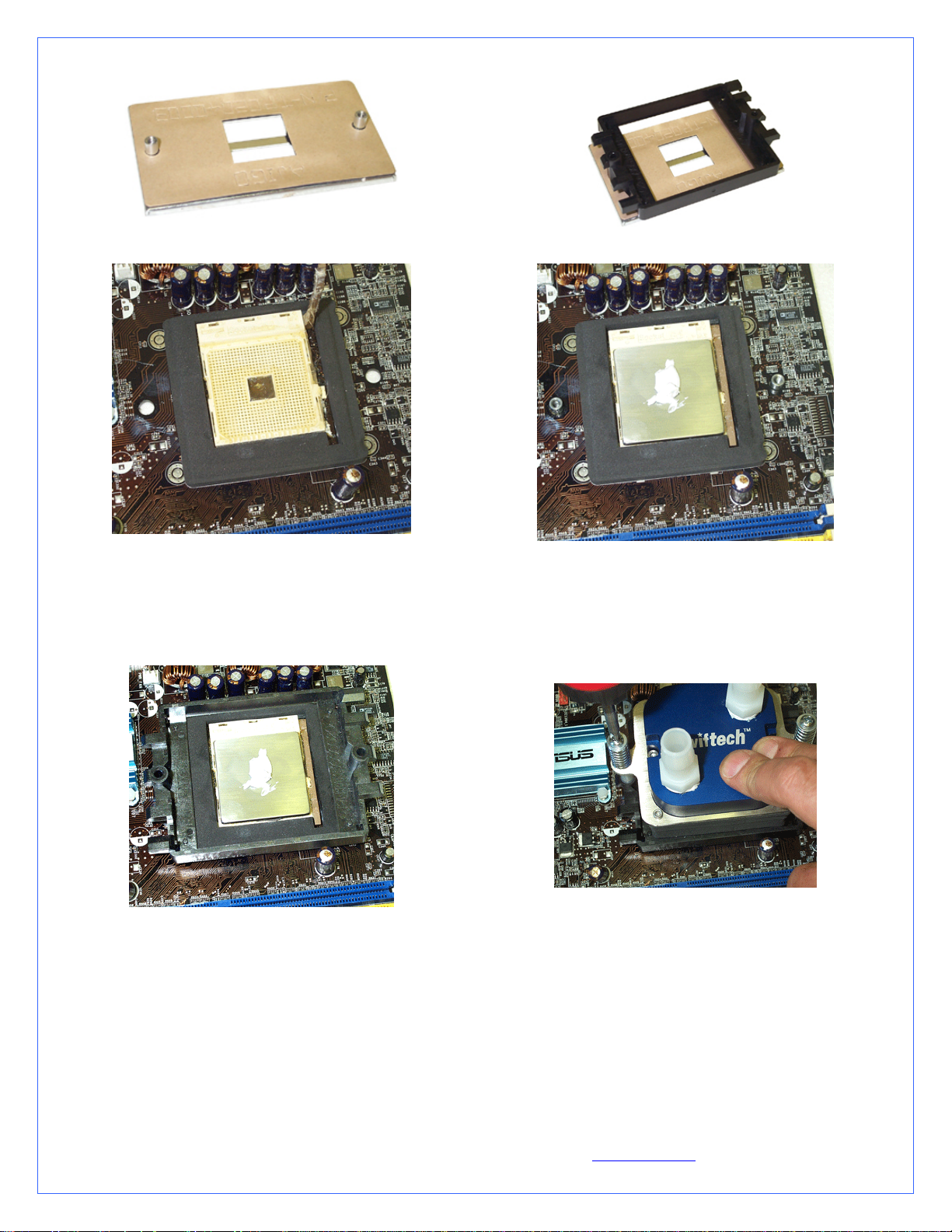
Part # AJ00264 backing plate alone
Part # AJ00172 complete retention frame & backing plate
Figure 6
Remove the peel-off paper back from the motherboard gasket,
and install it as shown above. The sticky side should be towards
the motherboard.
Insert the processor into the socket.
Since you have grease inside the socket, some hydraulic
pressure lift may occur: for this reason, make sure that the
Figure 7
processor sits perfectly flat, and is inserted all the way into the
socket. Then, drop a small amount of high quality thermal
compound into the center of the processor core.
Figure 9
Figure 8
Place the stock plastic retention over the gasket as shown above Secure the MCW5002-64T cooler to the motherboard by
alternatively and gradually tightening the 2 retention screws.
IMPORTANT WARNING: Solder joints of the wires to the thermoelectric module are extremely fragile. Bending the wires
at their root will break the solder joint, with no possible repair. Swiftech will not honor the warranty for broken
C. Hydraulic Installation
The MCW5002-T is shipped with ½” barb to 3/8” NPT nylon fittings. These fittings should be installed using
Teflon tape or plumbers “goop”. If fittings need to be replaced for a difference tubing size, do not use brass fittings,
because of the galvanic corrosion that will take place between copper or brass and the MCW5002-T aluminum
housing. Always use nylon fittings.
Copyright Swiftech 2005 – All rights reserved – Last revision date: 12-27-05 - Information subject to change without notice – URL: http://www.swiftnets.com
Rouchon Industries, Inc., dba Swiftech – 1703 E. 28
Inlet and outlet are interchangeable.
th
Street, Signal Hill, CA 90755 – Tel. 562-595-8009 – Fax 562-595-8769 - E Mail: Swiftech@swiftnets.com PAGE 18 of 32
Page 19
Type of Coolant:
For best performance, use 5 to 10% of Swiftech brand “HydrX” corrosion inhibitor mixed with distilled
water only .
Regular automotive anti-freeze is also acceptable. Automotive manufacturers recommend that not less than
25% is used.
NEVER use tap water, even for a short-term test.
Not following the above instructions constitutes misuse (*) of the product, and will void your warranty.
wires.
Now that the water-block installation is complete, please proceed with the rest of the components installation as described in Chapter
2.
II. COMPONENTS (OTHER THAN WATER-BLOCK) INSTALLATION
Set aside your motherboard/water-block assembly in a safe place, and start working on your chassis. There is no critical order in the
suggestions below, other than good common sense. Choices will depend on the layout of your own chassis.
1. S320-12 POWER SUPPLY KIT INSTALLATION GUIDE
Qty Item
1 S320-12 power supply installed in 5 ¼” adapter tray, screws
1 Electrical harness
1 Relay Switch
1 A/C socket adapter, stainless steel cover plate, screws
1 A/C cord
1 80mm fan guard with (4) snap rivets
Preamble
This kit has been designed to facilitate installation with as little modifications to the case as possible. It is however meant for advanced
users, well versed in installing computer components.
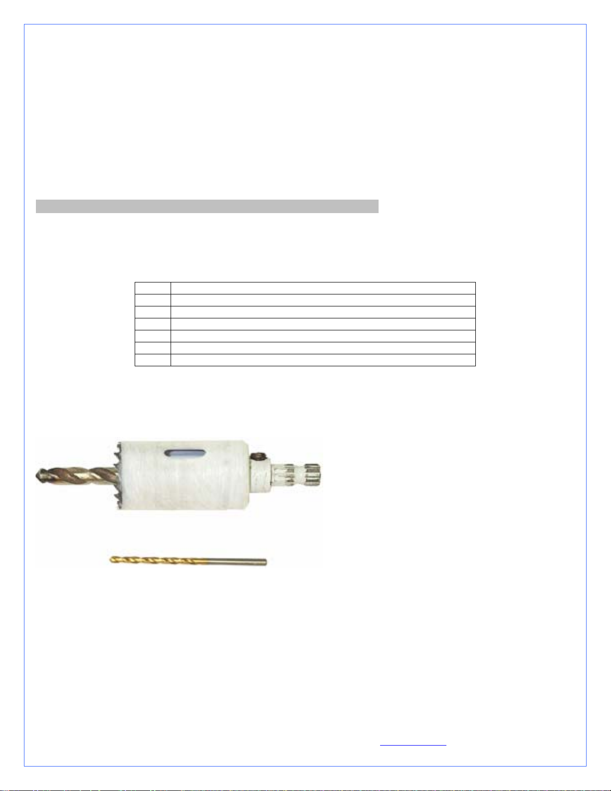
Specific tools needed to complete the
installation:
Power drill
1 ¼” (32mm) Bi-Metal hole saw to drill hole
for A/C socket
1/8” (3.17mm) Drill bit for A/C socket cover
mounting holes
Optionally: 3 ¼” Bi-Metal hole saw to drill an
80mm blow hole above the power supply fan
exhaust
General Rules:
Always work on a “naked” case, removing side panels, front bezel, and top panel, with no power supply installed.
Never work with electricity connected to the computer while work is in progress.
Strip the case “naked”: Since you will be making holes in the case, metal debris could be flying off into your components, and a
“naked” chassis will be easier to clean-up.
A. S320-12 Power supply installation
Install the power supply in a 5 ¼” bay, preferably in the uppermost slot as shown in figure 1. Use the provided screws to secure tray to
the chassis.
Copyright Swiftech 2005 – All rights reserved – Last revision date: 12-27-05 - Information subject to change without notice – URL: http://www.swiftnets.com
Rouchon Industries, Inc., dba Swiftech – 1703 E. 28
th
Street, Signal Hill, CA 90755 – Tel. 562-595-8009 – Fax 562-595-8769 - E Mail: Swiftech@swiftnets.com PAGE 19 of 32
Page 20
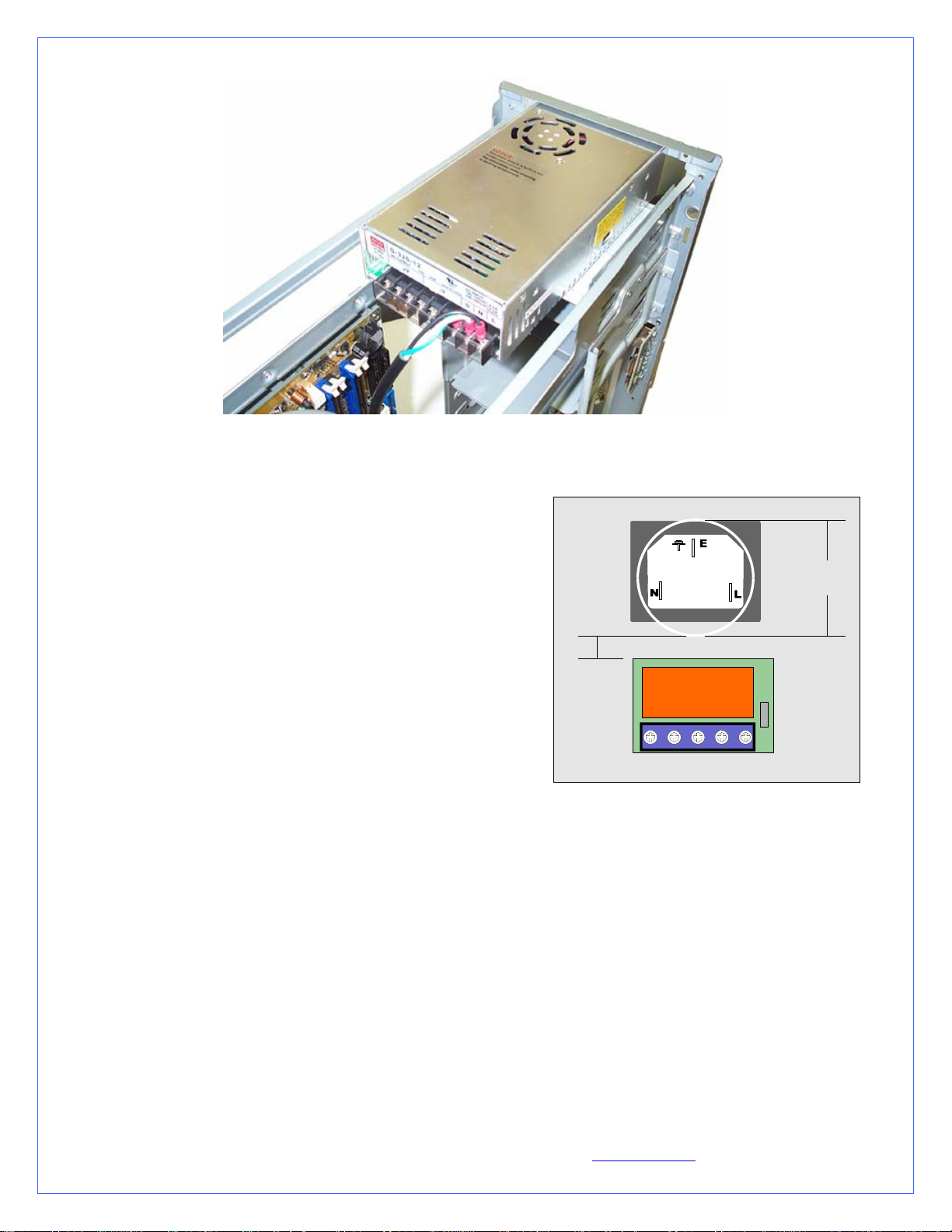
Figure 1
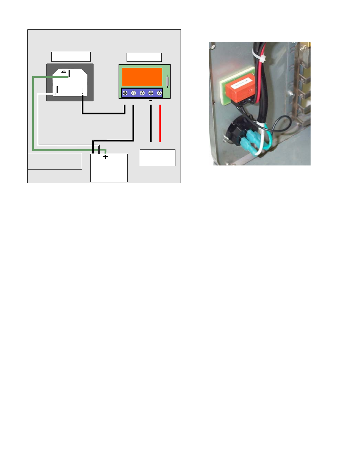
B. Relay Switch Installation
Find a suitable placement to drill a hole for the A/C socket adapter.
Leave sufficient room under or above the hole to install the relay
switch circuit board. A ¼” minimum clearance will be required
between the circuit board and the edge of the hole.
Make a 1.25” (32mm) diameter hole in the case, using a 1 ¼” BiMetal hole saw. De-burr the edges of the hole with sand paper.
Position and center the mounting plate over the hole as a template to
mark the locations of the plate’s mounting screws. Drill 2 holes of
.125” diameter for the mounting screws.
Install the mounting plate using the screws provided with your kit.
Insert the A/C socket inside the mounting plate.
Proceed with electrical connections as described in fig.3:
Black L wire from A/C socket to N\O (normally opened)
position on switch
Black L wire from S320-12 power supply to N\O position
on switch
White N wire from S320-12 power supply to N position on
A/C socket
Green Ground wire from S320-12 power supply to Ground
on A/C socket
The 4 pins Molex connector will then connect to the
computer power supply.
Note that connection of the TEC wires to the S320-12 power supply
will take place at the very end of the installation, once your
hydraulic circuit has been leak proofed (chapter 2.7)
A/C Socket
Hole
1.25"
Sp a c in g
0.25"
N\O
N\O
Pump’s relay switch circuit board
_
+
Figure 2
Copyright Swiftech 2005 – All rights reserved – Last revision date: 12-27-05 - Information subject to change without notice – URL: http://www.swiftnets.com
Rouchon Industries, Inc., dba Swiftech – 1703 E. 28
th
Street, Signal Hill, CA 90755 – Tel. 562-595-8009 – Fax 562-595-8769 - E Mail: Swiftech@swiftnets.com PAGE 20 of 32
Page 21
Relay switch connectio n diagram
The relay switch and A/C socket adapter installed
A/ C Socket
E
N
WARNING ! Alw ays disconne ct
from A /C power so urc e while
working with electrical devices.
L
N
L
S3 2 0-1 2
Re la y switc h
N\O
N\O
+
Ground + 12v
Com puter
Po w e r Sup p ly
Figure 4
Po w e r su p p ly
Figure 3
C. Power Supply ventilation
The following information is optional, and subject to existing ventilation in your particular chassis. Please disregard if your computer
chassis already features a blowhole, with or without fan.
The S320-12 power supply features a built-in temperature controlled fan, which activates as needed. Since the power supply is being
installed in a confined area, and in order to reduce a heat build-up inside the chassis, it is essential to optimize exhaust of the hot air
generated by the power supply. A blowhole will accomplish just this, and should be located as close to, or preferably directly above
the power supply exhaust vent. Ideally, a low CFM 80mm fan should be added, if space permits. Such solution will greatly reduce the
activity of the power supply built-in cooling fan, resulting in quieter operations, and lower temperatures both inside the computer and
in the power supply. If such fan is installed, it should be extracting air from the case (blowing towards the outside).
The template below provides holes dimensions for installation of such 80mm fan blowhole. A fan guard and snap rivets are provided
with the kit to complete such installation.
Copyright Swiftech 2005 – All rights reserved – Last revision date: 12-27-05 - Information subject to change without notice – URL: http://www.swiftnets.com
Rouchon Industries, Inc., dba Swiftech – 1703 E. 28
th
Street, Signal Hill, CA 90755 – Tel. 562-595-8009 – Fax 562-595-8769 - E Mail: Swiftech@swiftnets.com PAGE 21 of 32
Page 22
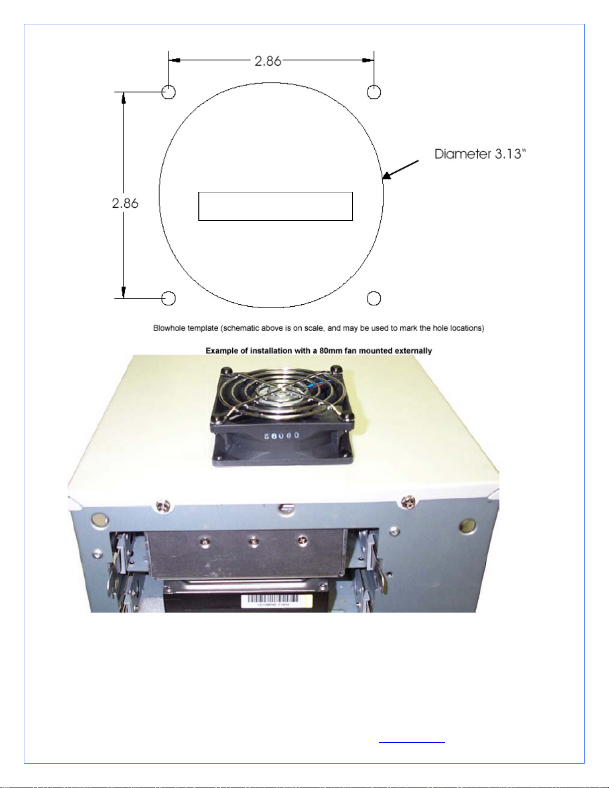
DOUBLE-CHECK DIMENSIONS
PRIOR TO USING AS TEMPLATE
Copyright Swiftech 2005 – All rights reserved – Last revision date: 12-27-05 - Information subject to change without notice – URL: http://www.swiftnets.com
Rouchon Industries, Inc., dba Swiftech – 1703 E. 28
th
Street, Signal Hill, CA 90755 – Tel. 562-595-8009 – Fax 562-595-8769 - E Mail: Swiftech@swiftnets.com PAGE 22 of 32
Page 23
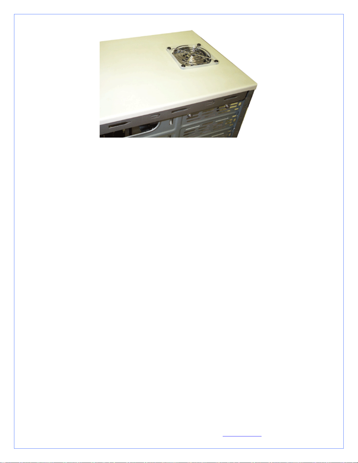
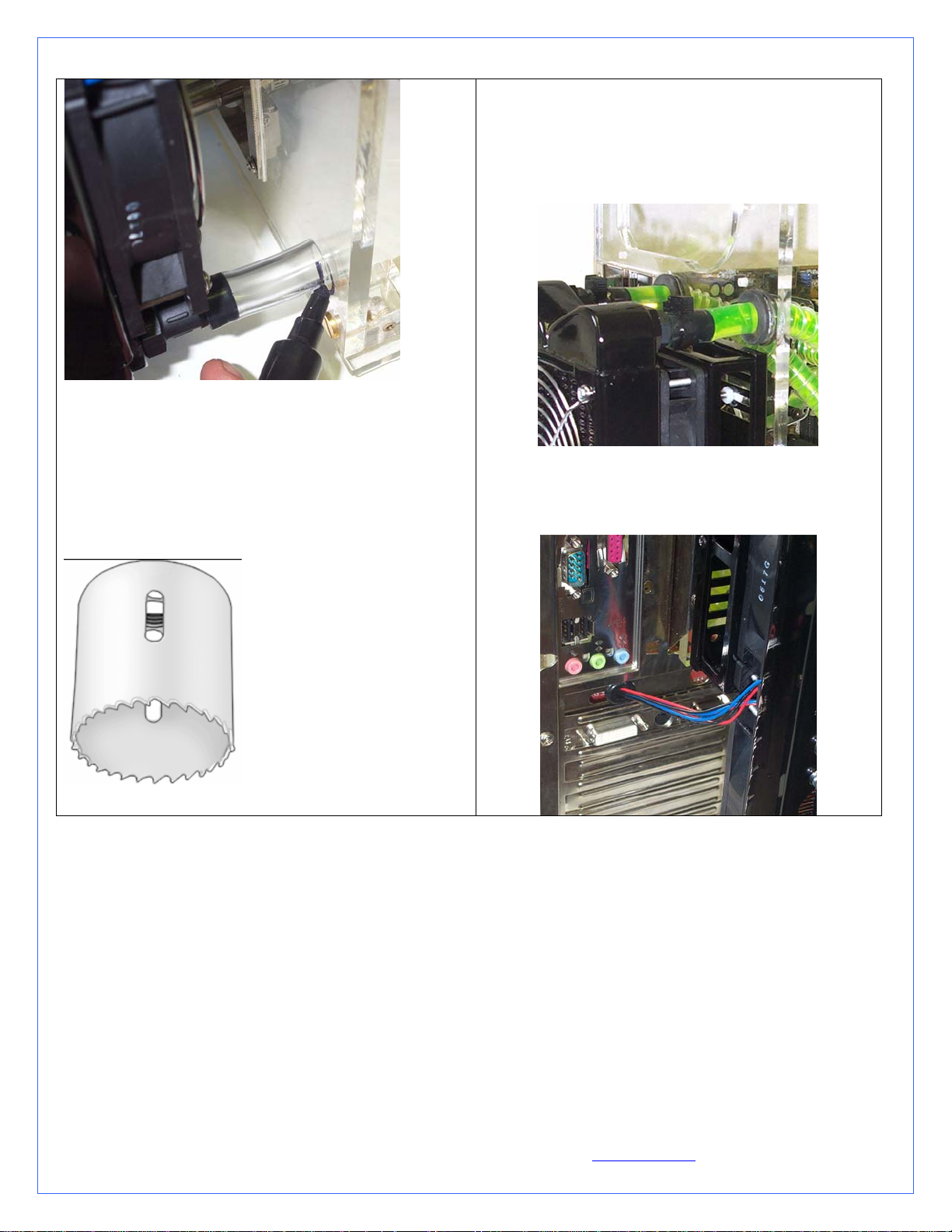
Another example of “blow-hole” installation
Now that your power supply is physically in place, let’s move on to the installation of the next component.
Note that connection of the TEC wires to the power supply will take place at the very end of the installation, once your hydraulic
circuit has been leak proofed (chapter 2.7)
2. MCR220 RADIATOR INSTALLATION
Preamble
The MCR220 dual 120mm radiator ships with the fans and the Radbox chassis already pre-assembled to the radiator. It is assumed
in effect that users will take advantage of our Radbox concept (external radiator installation) due to the benefits it provides and ease of
installation. In such context, the following installation guide describes this type of installation. We also recognize that due to various
considerations (cosmetics, space, or simply user preference) a number of users will wish to install the MR220 radiator internally.
Because of the large size of the radiator, it is most likely that an internal installation will require extensive modifications in most
computer cases. Because these modifications depend on the structure and dimensions of each individual chassis, we simply cannot
provide precise installation instructions to this effect. Here are some general guidelines that advanced “case-modders” should take into
consideration:
A. Radiator installation, general considerations
For optimum performance radiators require an unobstructed source of cool air. This dictates either an external mounting or one on/in
the case where the radiator will draw cool air from the exterior. The second consideration is the placement of the inlet and outlet
connections; at least one connection should be at the ‘top’ of the radiator to make it self-purging.
An external mounting can be effectuated by means of the RadBox affixed to the backside of the case and the tubing routed through
holes drilled in the case underneath the power-supply. This places the connections at the top of the radiator and it will preclude the
accumulation of air in the radiator.
Single 120mm fan radiators can be mounted over appropriately sized openings in a variety of cases; conversely, mounting a dual
120mm radiator is considerably more difficult and generally results in placing the radiator ‘inverted’ at the top, or ‘right side up’ at the
bottom. Note that the ‘inverted’ mounting places the inlet and outlet facing down; this mounting will accumulate air over time. Placing
the radiator ‘right side up’ in the case bottom will make the radiator self-purging, but it will gather dust VERY quickly if adjacent to
the floor. In any case, mounting a dual 120mm radiator inside a case will require some extensive case modifications for the air inlet.
B. Installation with the Radbox
Place the radiator assembly on the back of the computer to roughly estimate where it will fit best.
You need to consider the following clearance issues:
Copyright Swiftech 2005 – All rights reserved – Last revision date: 12-27-05 - Information subject to change without notice – URL: http://www.swiftnets.com
Rouchon Industries, Inc., dba Swiftech – 1703 E. 28
th
Street, Signal Hill, CA 90755 – Tel. 562-595-8009 – Fax 562-595-8769 - E Mail: Swiftech@swiftnets.com PAGE 23 of 32
Page 24
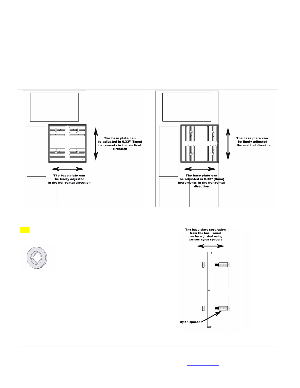
o Exit cables and connectors from various PCI devices: the Radbox base plate can be moved in both vertical and
horizontal directions to allow clearance for the cables.
o Opening the side panel once the Radbox is installed: the Radbox is supplied with various nylon spacers to separate
the base plate from the surface of the back-panel and to provide clearance for opening of the side-panel.
o Note that a chassis with 80mm fan opening(s) is likely to provide a very good range of adjustments. Conversely, a
chassis featuring a single 120mm fan opening the base-plate is a direct bolt on, but offers no adjustments, which
may or may not suit our installation for the purpose of positioning the radiator. In that case, it will be become
necessary to drill (4) mounting holes of 0.150” (~3.5mm) in diameter to install the base plate at the desired location.
C. Securing the base plate at the desired location
D. Fastening the radiator/Radbox assembly to the computer back-panel
TIP: In the package of assorted hardware coming with your
Radbox, locate the 4 little nylon retaining washers looking like
this:
Use these to secure the screws and nylon
spacers to the computer back-panel. This will hold the screws in
place while you adjust the Radbox back-plate.
Once satisfied with the position, bolt down the Radbox backplate with the provided nylon nuts.
Next, you will need to mark the location of the holes that must
be drilled to allow routing of the tubes through the computer
back-panel. You can cut two small pieces of the provided PVC
tubing and install these to the radiator hose barbs, then
temporarily mount the radiator assembly onto the back-plate.
The tubing will provide a convenient way to mark the position
of the holes as shown below:
Copyright Swiftech 2005 – All rights reserved – Last revision date: 12-27-05 - Information subject to change without notice – URL: http://www.swiftnets.com
Rouchon Industries, Inc., dba Swiftech – 1703 E. 28
th
Street, Signal Hill, CA 90755 – Tel. 562-595-8009 – Fax 562-595-8769 - E Mail: Swiftech@swiftnets.com PAGE 24 of 32
Page 25
Once the two holes are cut, de-burr the edges, and install the
grommets.
Install your radiator assembly onto the back plate.
Once the tubes are connected to the radiator,
the final results will look like so:
Remove the radiator assembly from the back-plate and mark the
center of the circle.
Two rubber grommets are provided with your kit so that you can
route the tube though the case without damaging the tubing with
the sharp edges of the hole. The required hole diameter for the
grommet is 7/8” (23mm).
To cut the holes, use a heavy-duty Bimetal hole saw of 7/8” in
diameter:
Finally, you need to route the fan wires through the backpanel. This can be done easily with the provided PCI adapter
plate featuring a hole and grommet for protection of the wire.
Copyright Swiftech 2005 – All rights reserved – Last revision date: 12-27-05 - Information subject to change without notice – URL: http://www.swiftnets.com
Rouchon Industries, Inc., dba Swiftech – 1703 E. 28
th
Street, Signal Hill, CA 90755 – Tel. 562-595-8009 – Fax 562-595-8769 - E Mail: Swiftech@swiftnets.com PAGE 25 of 32
Page 26

Example of Installation of the MCR220-QP radiator with Radbox
3. RE-INSTALLING THE MOTHERBOARD/WATER-BLOCK ASSEMBLY INTO THE CHASSIS
Once your radiator and S320-12 power supply are in place, make sure to clean-off any metal shavings left inside the case,
then go ahead and reinstall the motherboard/water-block assembly into the computer.
- Intentionally left blank -
Copyright Swiftech 2005 – All rights reserved – Last revision date: 12-27-05 - Information subject to change without notice – URL: http://www.swiftnets.com
Rouchon Industries, Inc., dba Swiftech – 1703 E. 28
th
Street, Signal Hill, CA 90755 – Tel. 562-595-8009 – Fax 562-595-8769 - E Mail: Swiftech@swiftnets.com PAGE 26 of 32
Page 27

4. MCP655 PUMP INSTALLATION
A. General Use
The MCP655 pump is a magnetically driven centrifugal pump
featuring a 12 V DC motor. It requires no maintenance when used
with de-mineralized water and the appropriate anti-fungal
additives. We recommend using 5 to 10% of Swiftech’s HydrX
as an additive. The pump is designed to be connected to your
computer power supply using the standard Molex 4 pin
connectors.
The MCP655 pump is neither submersible, nor self- priming. The
inlet needs to be continuously supplied with fluid for the pump to
operate properly.
B. Installation
Determine the best location for your pump by observing how
the tubing will be routed to the rest of the circuit. Sharp bends
in the tubing should always be avoided to prevent kinks,
which will reduce or completely prevent flow of the cooling
fluid.
In general, we recommend installation of the pump at the
bottom of the chassis.
The base of the pump features a soft neoprene pad coated with
strong adhesive material. Only once the final location for the
pump has been determined, go ahead and peel-off the pad’s
protective paper, and press the pump against the chassis
surface. The surface should be clean, and non greasy. Thrubolts are also provided for permanent installation, and require
drilling holes in the chassis.
The back of the pump features a potentiometer to allow users
to vary the pump speed from 1800 to 4800 rpm. Full speed is
suggested for maximum performance. When reducing the
pump speed, the operating noise will also decrease
proportionally, but so will the performance. A flow rate chart
is provided below
C. Precautions
The MCP655 pump should never be run dry, even for a quick
test. You should always prime the pump with fluid before you
start operating it (see warranty note *).
Use of coloring die or fluorescent additives containing
particulate fillers will cause excessive wear to the pump’s impeller
bearing (see warranty note **).
Error!
Notes:
Always make sure to directly connect the RESERVOIR
DISCHARGE to the PUMP INLET.
Please refer to paragraph 2.6 for an important note
concerning connection of the tubing to the pump.
Copyright Swiftech 2005 – All rights reserved – Last revision date: 12-27-05 - Information subject to change without notice – URL: http://www.swiftnets.com
Rouchon Industries, Inc., dba Swiftech – 1703 E. 28
th
Street, Signal Hill, CA 90755 – Tel. 562-595-8009 – Fax 562-595-8769 - E Mail: Swiftech@swiftnets.com PAGE 27 of 32
Page 28

Copyright Swiftech 2005 – All rights reserved – Last revision date: 12-27-05 - Information subject to change without notice – URL: http://www.swiftnets.com
Rouchon Industries, Inc., dba Swiftech – 1703 E. 28
th
Street, Signal Hill, CA 90755 – Tel. 562-595-8009 – Fax 562-595-8769 - E Mail: Swiftech@swiftnets.com PAGE 28 of 32
Page 29

5. MCRES-MICRO RESERVOIR INSTALLATION
ITEM
NO.
1 MCRES-MICRO Reservoir 1
2
3 O-RING-9557K473 Barb fitting O-Ring 2
4 pg7-o-ring
5 pg7-plug Pg7 Fill-cap 1
6 MOUNTING HARDWARE 3
1-4“ NPSM x 3-8“ and 1-2“barb
PART NUMBER DESCRIPTION QTY.
Barb fitting
Fill-cap o-ring
2 pairs
each
1
6a
6b
6c
6d
7 panel 1
90272A152-6-32x0500ph ilips 6-32 x 7/8" (22mm) Philips screw 1
90760A007
washer-91007A614
WASHER-RUBBER-437X150X092 Rubber Washer 1
6-32 Nut 1
Lock Washer
1
Figure 1
A. Installation
The MCRES-MICRO can be installed in any suitable location meeting its form factor requirements. For filling and bleeding purposes,
it is preferable to hold or to install the MCRES-MICRO at the highest point of the liquid cooling loop. However, once filled and
hermetically closed, the reservoir can be installed practically anywhere as long as it is kept upright as shown in figure 1. Also, to
facilitate the filling and bleeding operations, you might want to wait until the circuit has been filled-up before you fasten the reservoir
permanently to the chassis.
B. Fastening the device to the case
Copyright Swiftech 2005 – All rights reserved – Last revision date: 12-27-05 - Information subject to change without notice – URL: http://www.swiftnets.com
Rouchon Industries, Inc., dba Swiftech – 1703 E. 28
th
Street, Signal Hill, CA 90755 – Tel. 562-595-8009 – Fax 562-595-8769 - E Mail: Swiftech@swiftnets.com PAGE 29 of 32
Page 30

Two mounting methods can be used
o Permanent mount with the provided mounting hardware as shown in figure 1. Three holes will need to be drilled for
a permanent mount. Simply use the reservoir as a template to mark the hole locations, and use a 0.150” (4mm) drill
bit to drill the holes. Make sure to clean up any metal shavings from the case once you are done.
o Easy mount, with the provided Velcro strips. This is a fairly secure mount, as we use extra strong Velcro. However,
if your computer is to travel often (LAN parties for example), a permanent mount remains more suited for a more
reliable fastening of the device.
The only critical precaution to take when installing the reservoir is to make sure that the discharge line (“Out to pump inlet”
in figure 1) is directly connected to the inlet of the pump. In other words, the pump (inlet) should be the first device
connected to the reservoir discharge. Using a different routing will make the filling and bleeding of the circuit difficult, and
may prevent the pump to prime properly.
6. TUBING INSTALLATION
A. Preamble: difficult installation of the tubing with the MCP655 pump
Once your radiator, pump and reservoir are in place, it is now time to connect all the elements of the circuit together.
Your kit comes with 7/16” ID (5/8” OD) tubing. This type of tubing was specifically selected following suggestions made by our
enthusiast users because it offers very low flow restriction, similar to that of true ½” ID tubing, without the bulk of true ½” (which is
¾” OD and therefore hard to work with). This tubing will fit easily onto standard ½” barbs EXCEPT for the MCP655 pump. In effect,
the design of the hose barbs on this pump makes it quite difficult to install this slightly smaller tubing. Two things can be done to ease
this process:
Rub the pump barbs with liquid soap to make them slippery
Soften-up the extremity of the tubes by dipping them in a glass of boiling water for about 20 to 30 seconds (boil some water
in a microwave oven, then dip the extremity of the tube).
Then work the tube around the pump hose barbs by pushing it firmly. Be patient, it is not easy but it does work.
B. Preparing the coolant
Your kit comes with a 2 Oz (60ml) bottle of Swiftech’s specially formulated HydrX concentrated coolant. The product should be
mixed with distilled water only. Simply empty the concentrated coolant into a 33 fl oz (1 liter) plastic bottle, and complete filling with
distilled water. Your coolant is now ready. Note: a 5% mix might still allow some algae formation over prolonged usage if your
system is continuously exposed to daylight (such as a clear acrylic case for example). Under such circumstances, we would suggest
using a 10% mix, and mixing the content of the bottle to ½ l of distilled water only. ½” a liter is normally sufficient to fill-up a typical
cooling loop.
C. Precautions of use with the MCRES-Micro reservoir
Use of alcohols (Alcohol Allyl, Amyl, Benzyl, Ethyl (Ethanol), Isopropyl, Methyl (Methanol), n-Butyl) or antifreeze products
containing the listed alcohols is prohibited as it will result in deterioration of the reservoir over-time, and will void your warranty.
Resistance to Ethylene and Methylene glycol used in antifreeze products is excellent.
Minimum Operating Level is situated at the Swiftech Logo (approximately ½” of the reservoir). The reservoir should not be operated
below this level, which could result in degradation of the system cooling.
D. Pre-cutting the tubing to length and tube routing
With all the components in place, it will be easy to estimate the length of tubing segments necessary between each component.
The following table shows a typical tube routing. This setup may change depending on the relative position of the components inside
your chassis. The only strict requirement is that the reservoir discharge be always connected directly to the pump inlet (“directly”
should be understood as “with no other components in between the reservoir and the pump”)
Copyright Swiftech 2005 – All rights reserved – Last revision date: 12-27-05 - Information subject to change without notice – URL: http://www.swiftnets.com
Rouchon Industries, Inc., dba Swiftech – 1703 E. 28
th
Street, Signal Hill, CA 90755 – Tel. 562-595-8009 – Fax 562-595-8769 - E Mail: Swiftech@swiftnets.com PAGE 30 of 32
Page 31

Reservoir discharge to pump
inlet
Pump discharge to
Radiator inlet
Radiator discharge to
CPU Water-block
inlet
CPU Water-block
discharge to reservoir
inlet
Loop completed
Connect the tube segments to the components, and secure them with the provided hose-clamps.
E. Re-installing your computer power-supply
Prior to fill-up the circuit, you will need to re-install your power-supply in order to start-up the pump during the fill procedure. You
must be able to start the PSU without it being connected to the motherboard. While the Internet contains numerous references on how
to use a paper-clip to short-out pin 13 and 14 of the 20 pin ATX connector as shown below, we nonetheless recommend instead using
a power-supply tester. A wide variety of these common devices are available on the Internet (Google key word: “PSU tester”), and
among Swiftech resellers (www.frozencpu.com, www.Directron.com, www.newegg.com, etc.).
13
14
F. Filling-up the circuit
Simply pour the coolant that you prepared into the reservoir – carefully to avoid spills, allowing
the circuit to fill-up by simple gravity. Note: for the gravity to take effect the reservoir should be
placed or held at the highest point of the cooling circuit.
Allow the fluid to fill-up the tubes by gravity AT LEAST past the pump. In effect, the pump
inlet and outlet must be full of fluid in order for the pump to operate properly.
Once the reservoir is full, seal the fill port back with its cap in order to avoid any spills, and start-
up the pump: the reservoir will quickly (within 1 second) empty itself. Immediately turn off the
pump as you do not want the pump to run dry (without fluid) which will damage it rapidly;
Top-off the fluid in the reservoir to the maximum level, and restart the pump. You need to repeat
this operation 3 to 4 times, until the circuit is finally full of coolant.
Then, allow the system to run 20 to 30 minutes uninterrupted to clear all the micro-bubbles and
foam, and finally top-off the level one last time.
Your liquid cooling circuit is now ready, and you may permanently install the reservoir.
Allow the system to run for 3 to 6 hours and frequently inspect all your connections for
possible leaks before you electrically reconnect your PC components (motherboard, hard
drives, etc.)
G. Post-installation no te: Draining the system
You will need to disconnect a line from one of the lowermost components. Procure a bucket large enough to receive approximately 1
liter of fluid, and place the bucket underneath the connection that you intend to “break”. Disconnect the line, and place both ends into
the bucket.
Do not forget to open up the fill-cap from the MCRES-MICRO to allow the fluid to completely escape.
7. ELECTRICAL CONNECTION: TEC TO S320-12 POWER-SUPPLY
Now that your liquid cooling circuit has been leak proofed, you can safely proceed with the connection of the TEC device to the S32012 meanwell power supply.
Your TEC module has been measured to draw 18 amps at 12 volts, whereas the S320-12 is rated for 25 amps. If you need to, you
can thus connect other devices to this power supply, drawing up to 6 amps (~70 Watts at 12 volts). Note that the more current you
draw on this unit, the more heat it will develop. Proper ventilation is therefore of the utmost importance to guarantee a long life to
your component.
Copyright Swiftech 2005 – All rights reserved – Last revision date: 12-27-05 - Information subject to change without notice – URL: http://www.swiftnets.com
Rouchon Industries, Inc., dba Swiftech – 1703 E. 28
th
Street, Signal Hill, CA 90755 – Tel. 562-595-8009 – Fax 562-595-8769 - E Mail: Swiftech@swiftnets.com PAGE 31 of 32
Page 32
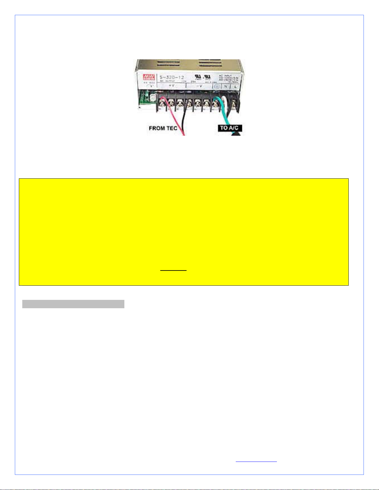
The TEC module is provided with “bare wires” to facilitate installation with screw type terminals such as featured in the S320-12
power supply
Connect red wire from TEC module to the +V terminal, and black wire to the –V terminal as shown in figure 10 below
Figure 10
A euro-style connector is provided with your kit in case you needed to extend the wires of the TEC to the power supply. Please only
use 16 gage stranded wire. Note another method to connect the extensions to the existing wires is to use terminal splices, or solder the
butts, and insulate them with shrink tubing.
CCRRIITTIICCAALL RREECCOOMMMMEENNDDAATTIIOONNSS MMUUSSTT RREEAADD!!!!!!
Never run a thermoelectric module without coolant flowing in the circuit. This will result in catastrophic failure of the
cooling element, and may cause any/all of the following:
Tubing to burst open due to coolant overheating
Permanent failure of the Peltier module
Permanent damage to the CPU and/or motherboard due to excess heat
If you run your computer unattended for extended periods of time, it is also a good practice to setup an alarm temperature,
which will shut down the computer in case the CPU overheats. Such alarm/shut down process must be tested and fully
functional.
WARNING! Wires from the thermoelectric module do get hot (this is normal). Make sure that the wires do not touch
devices that are heat sensitive, such as vinyl tubes for example. Heat from the wires may cause the vinyl to deform, and/or
to burst.
III. PERIODIC MAINTENANCE
A. Keeping your system clean
Every 6 months: dust off the radiator fins and fan. You can use a can of compressed air for example, available in most electronic
supply stores. If you live in a very dusty area, you should perform this task at closer intervals. It is essential to maintain the optimum
performance of your cooling system.
B. Fluid Level
Inspect the level of liquid inside the circuit, and refill if necessary. Evaporation in this closed circuit is extremely limited, but still
present due to permeability in the vinyl lines.
Every 12 to 18 months or as necessary: top-off the fluid with a mix of distilled water and 5 to 10% Hydrx fluid.
C. Draining the system
You will need to disconnect a line from one of the lowermost components. Procure a bucket large enough to receive approximately 1
liter of fluid, and place the bucket underneath the connection that you intend to “break”. Disconnect the line, and place both ends into
the bucket. Do not forget to open up the fill-cap from the MCRES-MICRO to allow the fluid to completely escape.
Copyright Swiftech 2005 – All rights reserved – Last revision date: 12-27-05 - Information subject to change without notice – URL: http://www.swiftnets.com
Rouchon Industries, Inc., dba Swiftech – 1703 E. 28
th
Street, Signal Hill, CA 90755 – Tel. 562-595-8009 – Fax 562-595-8769 - E Mail: Swiftech@swiftnets.com PAGE 32 of 32
 Loading...