

Page 1

H20-220 COMPACT
INSTALLATION GUIDE
GUIDE D’INSTALLATION
MONTAGEANLEITUNG
GUÍA DE INSTALACIÓN
Page 2

TABLE OF CONTENTS
TABLE DES MATIERES
INHALTSVERZEICHNIS
CONTENIDO
1/ SYSTEM OVERVIEW………………………………………………………….
2/ PREPARING FOR INSTALATION……………….…………………………..
3/ RADBOX & RADIATOR INSTALLATION……………………………….…...
4/ SYSTEM INSTALLATION……………………………………………………..
5/ FILLING UP AND TESTING THE SYSTEM…………………………………
6/ FINALISING INSTALLATION………………………….………………………
7/ ELECTICAL CONNECTIONS & PRODUCT USAGE……………………….
8/ ADDING VGA COOLING & OTHER DEVICES TO THE LOOP…………...
9/ OTHER SWIFTECH LIQUID COOLING PRODUCTS………………………
10/ SUPPLEMENTAL AMD® INSTALLATION GUIDE ……………….……....
1/ INTRODUCTION ………………………………………………………….……
2/ OPERATIONS PREALABLES ……………………………………………......
3/ INSTALLATION DE L’ADAPTATEUR RADBOX ET DU RADIATEUR …..
4/ INSTALLATION DU SYSTEM DE REFROIDISSEMENT ………………….
5/ REMPLISSAGE ET TEST DU SYSTEM DE REFROIDISSMENT………...
6/ INSTALLATION FINALE .……………………………………………………...
7/ CONNEXIONS ELECTRIQUES ET UTILISATION DU PRODUIT ………..
8/ INTEGRER UN REFROISSEMENT GRAPHIQUE………………………….
9/ AUTRES PRODUITS DE REFROIDISSEMENT LIQUIDE SWIFTECH…..
10/ GUIDE D’INSTALLATION SUPPLEMENTAIRE POUR AMD®…………..
1/EINLEITUNG…………………………..…………………………..……………..
2/VORHERIGEVORBEREITUNGEN…………………………..………………..
3/ RADBOX UND RADIATOR INSTALLATION…………………………..…....
4/ INSTALLATION VON DEM FLÜßIGKÜHLSYSTEM………………………..
5/ FÜLLEN UND TESTEN DAS FLÜßIGKÜHLSYSTEM ……………………..
6/ LETZTE INSTALLATION……………………………………………………….
7/ ANSCHLUSSE UND DAS SYSTEM BENUTZEN…………………………..
8/ EIN GPU-GRAFIKKARTENKÜHLER (UND/ODER CHIPSATZ KÜHLER)
IN DEM FLÛßIGKÛHLSYSTEM INTEGRIEREN ……………………………..
9/ SWIFTECH OPTIONEN……………………………..…………………………
10/ MONTAGEANLEITUNG FÜR AMD® SOCKEL……………………………
1/ INTRODUCCIÓN ……………………………………………………………….
2/ OPERACIONES PREVIAS …………………………………………………....
3/ INSTALACIÓN DEL ADAPTADOR RADBOX Y DEL RADIATEUR ………
4/ INSTALACIÓN DEL SISTEMA DE ENFRIAMIENTO ………………………
5/ LLENADO Y TEST DEL SISTEMA DE ENFRIAMIENTO………………….
6/ INSTALACIÓN FINAL………………………………………………………….
7/ CONNEXIONES ELÉCTRICAS Y UTILIZACIÓN DEL PRODUCTO……..
8/ INTEGRAR EL ENFRIAMIENTO GRÁFICO (Y/O CHIPSET) ……………
9/ OTROS PRODUCTOS DE ENFRIAMIENTO LÍQUIDO SWIFTECH…..…
10/ GUÍA DE INSTALACIÓN SUPLEMENTARIA PARA AMD®. ……………
3700 Industry Ave., Suite 104
Lakewood, CA 90712
US TOLL FREE (888) 857-9438
T. (562) 595-8009
F. (562) 595-8769
www.swiftech.com
Help@swiftech.com
Swiftech
1
1
2
3
5
6
6
7
7
8
9
9
10
13
13
14
14
15
15
16
17
18
18
19
21
22
22
23
23
24
25
26
26
27
29
30
30
31
31
32
Page 3
Installation Guide
Introduction
Congratulations on your purchase of a Swiftech® H20-220 COMPACT Liquid Cooling System!
While all attempts have been made to make the installation of this system user friendly, please
note that this system is intended for users that are well versed in installing computer components.
General guidelines
Please read this guide carefully and entirely before you start the installation.
Never work with electricity connected to the computer while work is in progress.
During installation the motherboard must remain disconnected from the power-supply at all
times.
In case of a spill or leak on the motherboard, do not panic! As long as the motherboard is not
electrically connected, no harm is done. You must however thoroughly dry the exposed area,
using a hair dryer for example, and wait a minimum of 6 to 8 hours prior to re-connecting the
motherboard to its power source.
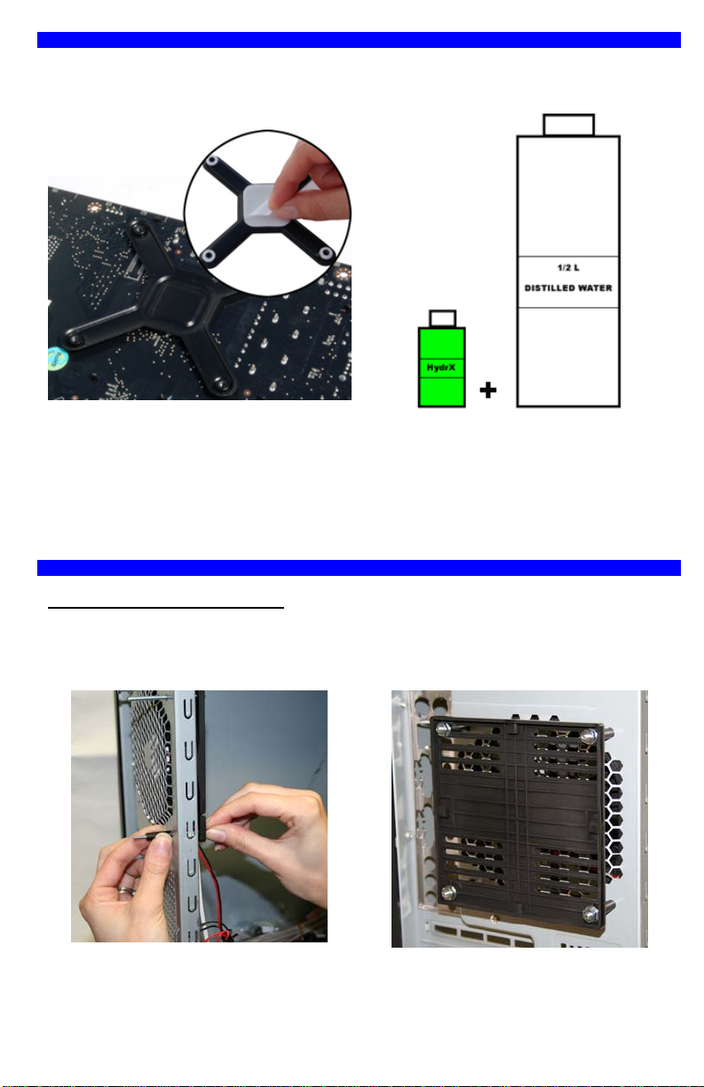
What is needed for the installation that is
• ½ Liter (½ qt) of distilled water (use of
distilled water is mandatory) to mix the
coolant.
• A power supply tester (or a simple paper
clip) to start-up the power supply without
connecting it to the motherboard.
• Rubbing Alcohol or electronic degreaser
for cleaning purposes.
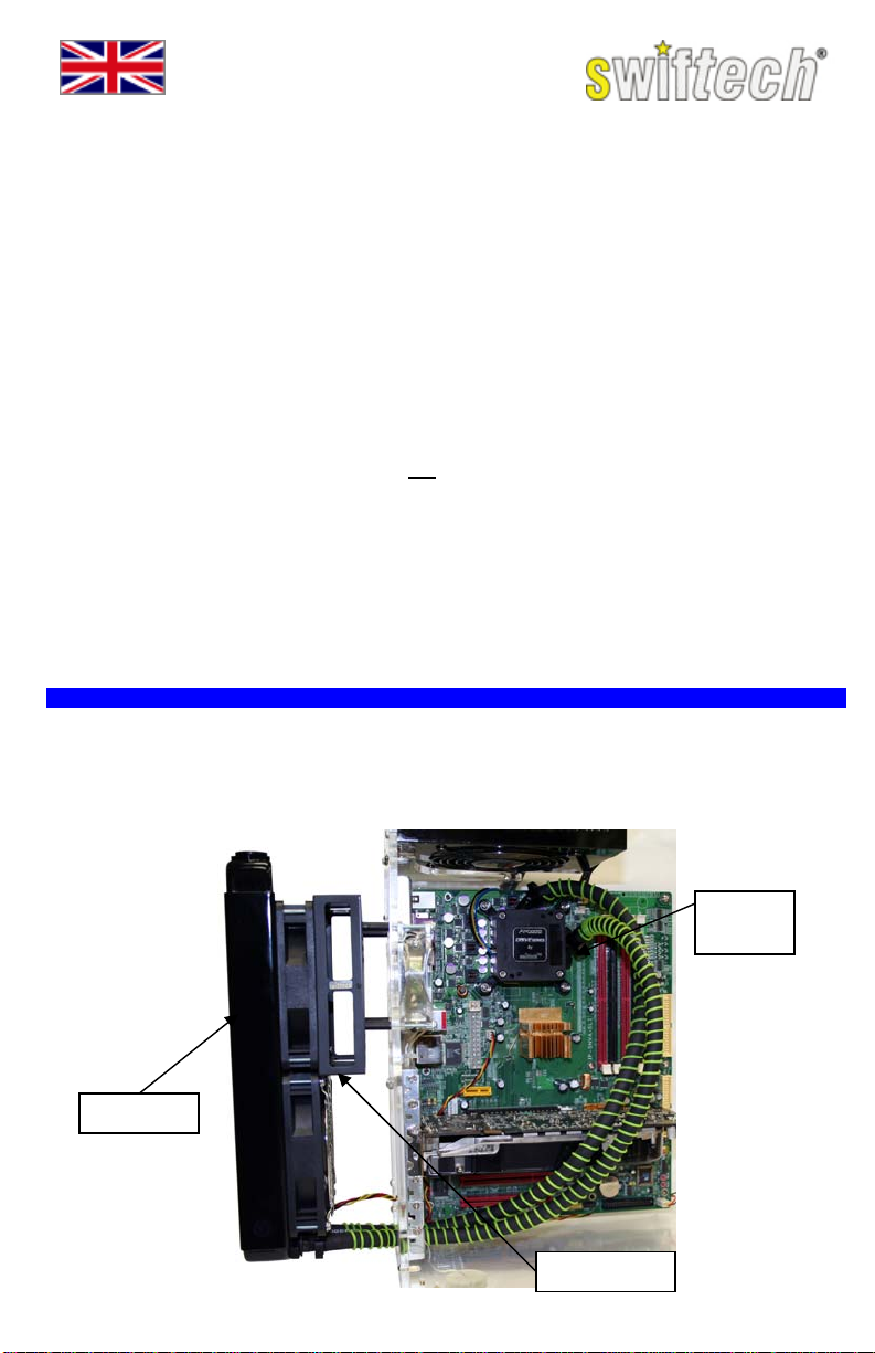
11// SSYYSSTTEEMM OOVVEERRVVIIEEWW
A typical CPU cooling installation is presented below. The included “Radbox” allows an easy
installation with a majority of mid and full tower cases by locating the oversized radiator at the back
of the chassis, thus optimizing cooling performance while leaving plenty of clearance for all the I/O
cables.
H20-220 Compact
not included in the kit?
• A pair of scissors to cut the tubing.
• A flat and a Philips screw drivers to fasten
the components.
• A pair of long nose pliers to fasten the hose
clamps.
• A 9/16 “deep” socket (14mm) to fasten the
fittings (preferred but not mandatory).
Radiator
Page 1
“Radbox”
Apogee
Drive
Page 4
22// PPRREEPPAARRIINNGG FFOORR IINNSSTTAALLLLAATTIIOONN
AMD® systems: the Apogee™ Drive is pre-assembled for installation with Intel® socket 775
compatible motherboards. Please refer to the Apogee™ Drive AMD® supplemental installation
guide (page 8) prior to proceeding hereafter.
SETTING UP THE APOGEE DRIVE WITH
INTEL® SYSTEMS
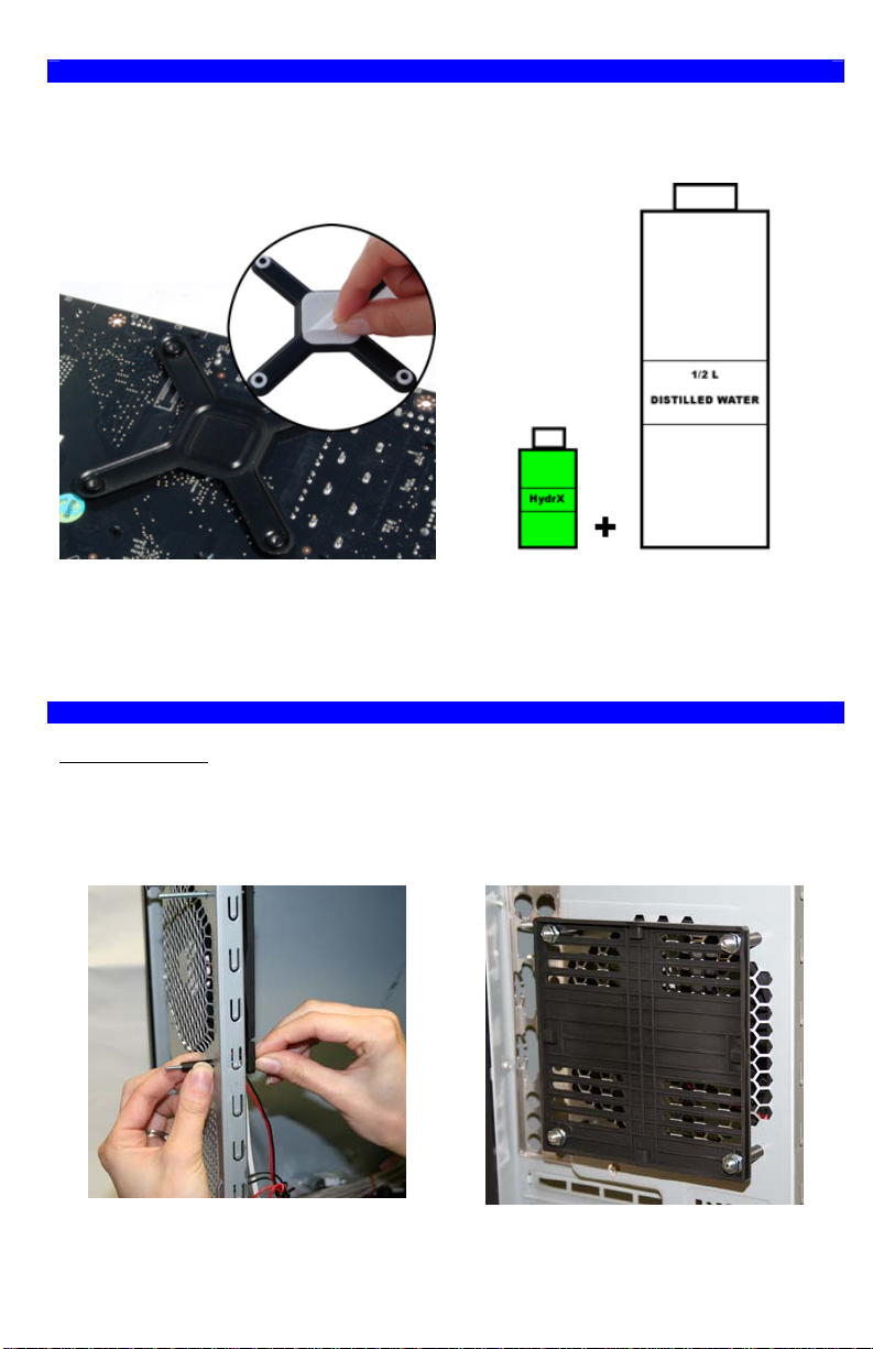
Peel-off the protective paper from the backplate stickers, and press the back-plate in place
behind the motherboard socket, then install the
motherboard inside of the case following
manufacturer instructions.
33// RRAADDBBOOXX && RRAADDIIAATTOORR IINNSSTTAALLLLAATTIIOONN
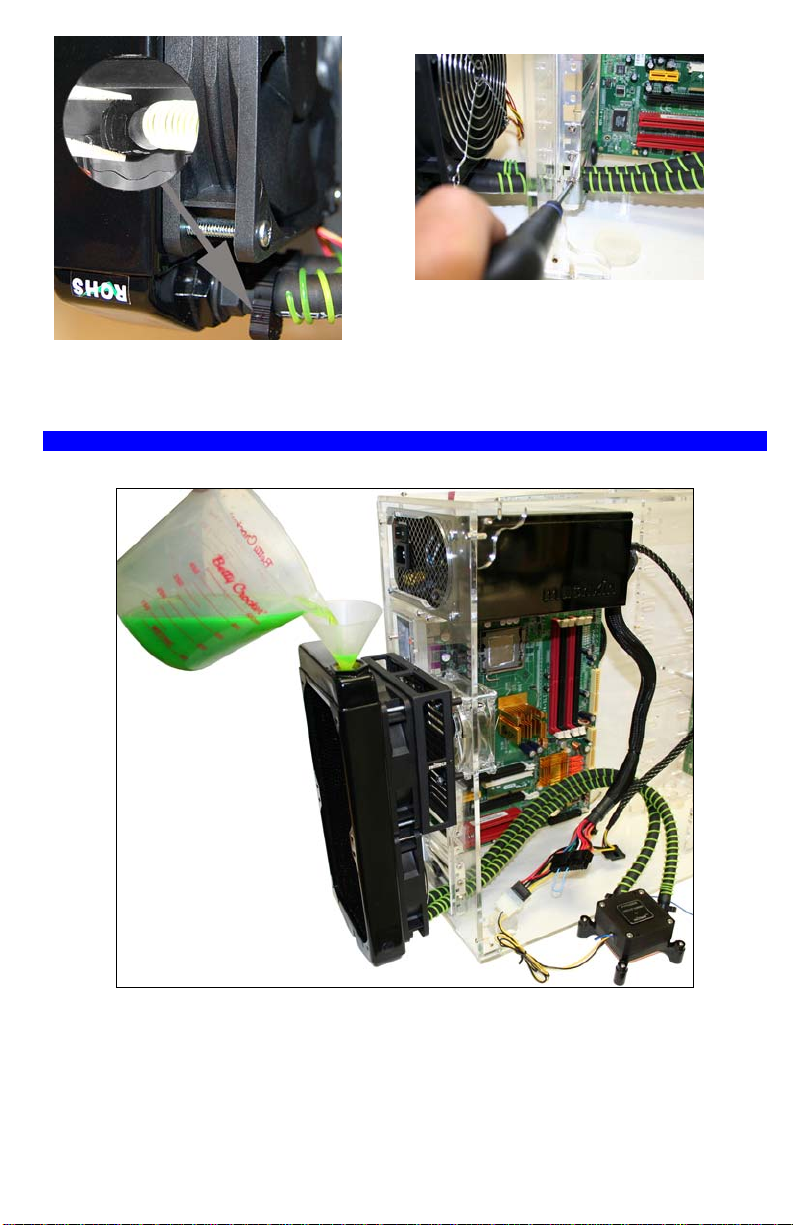
Radbox installation
In order to attach the Radbox to the back of the case and whenever possible you should utilize the
existing holes used for fastening the computer exhaust fan to the case. The existing exhaust fan
can stay in place; simply replace its fasteners by the longer screws provided with your kit in the
Radbox hardware pack. We show an example using a 120mm fan below. The Radbox can also be
used with 92, 80, and even 60mm hole patterns and adjusted as shown on page 3.
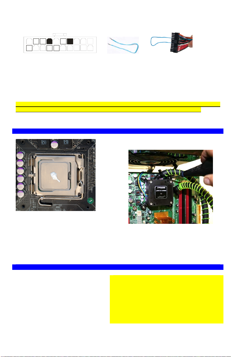
Mix the supplied bottle of Hydrx concentrated
coolant to ½ Liter (½ qt) of distilled water.
Page 1
1. Insert the provided screws thru the fan and
case, and fasten with the provided threaded
spacers.
2. Bolt the Radbox base plate to the posts with
the provided washers and nuts. Do NOT forget
the washers!
Page 2
Page 5
When the exhaust fan is smaller than 120mm, such as 92mm, 80mm or even 60mm, the base
plate can be adjusted as shown above.
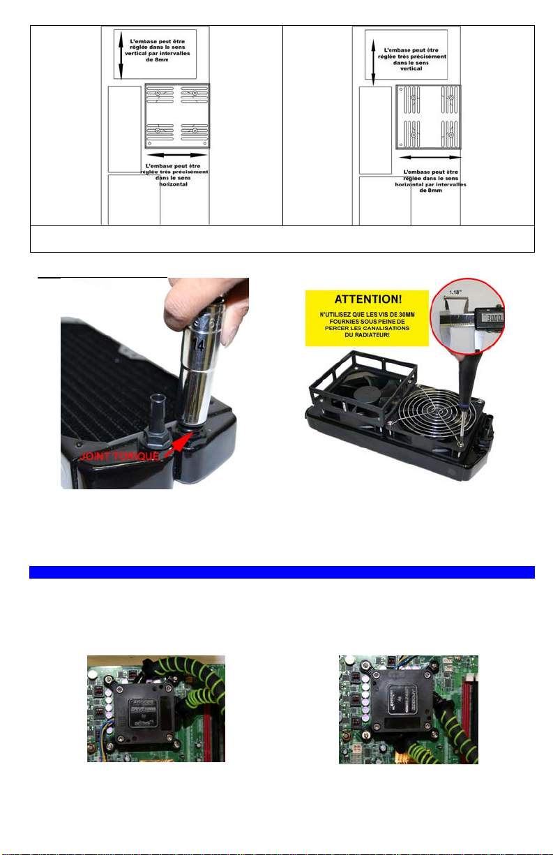
Radiator Preparation
1. Fasten the provided fittings to the radiator
using a 9/16 (14mm) deep socket, without
forgetting the o-rings! Lock the fittings firmly.
44.. SSYYSSTTEEMM IINNSSTTAALLLLAATTIIOONN
In order to evaluate the appropriate length of tubing that will be needed between the components
the Apogee™ Drive will need to be temporarily mounted to the motherboard at first, then
dismounted to fill-up the system, and finally remounted permanently.
Note: In a vertical system, the Apogee™ Drive can only be oriented in two different positions as
shown below.
Position A Position B
2. Install the provided fans, fan guard, and
Radbox housing as shown above, only using
the provided 30mm (1.17”) long screws. Please
read the critical warning above to prevent
permanent damage to the radiator.
Page 3
Page 6
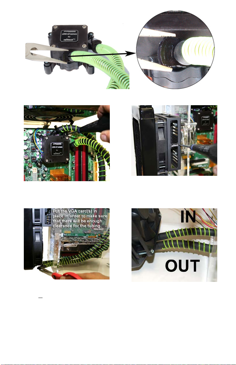
1. Attach the tubes to the Apogee™ Drive fittings and clamp them as shown. The clamps should
always be completely closed to provide a proper seal.
2. Place the Apogee Drive on the CPU, and
then fasten the screws just enough to hold it in
place. Fully tightening of the screws is not
necessary at this time.
4. Route the tubing thru the PCI slot the most
directly in front of the radiator fittings, and cut
the tubing
slack to the tube, so that it will not kink.
if necessary. Always leave sufficient
3. Fasten the Radiator/Radbox assembly to the
Radbox base plate using the provided (4)
screws.
5. Attach the tube coming from the Apogee
Drive OUTLET (see label on the Apogee™
Drive), to the Radiator INLET as shown above.
Page 4
Page 7
6. Fasten both hose clamps to the radiator inlet
and outlet fittings, using a pair of long nose
pliers.
55// FFIILLLLIINNGG--UUPP AANNDD TTEESSTTIINNGG TTHHEE SSYYSSTTEEMM
System Setup Overview
7. Insert and fasten the provided PCI pass-thru
bracket, and finally route the fan electrical
connectors through the rubber grommet.
a/ Remove the Apogee™ Drive from the motherboard, and place it flat on your bench as shown
above; then connect the Apogee™ Drive power plug to the Power supply.
b/ In order to fill-up the liquid cooling system with coolant and test it, you will need to be able to run
the Apogee™ Drive pump. This necessitates that you start-up the power supply while it is not being
connected to the motherboard.
It is possible to turn the PSU on and off with its power switch by using a simple paper clip to
connect pin 14 (PS-ON – GREEN) to any BLACK wire (ground) on the 20 pin ATX connector as
shown hereafter. However, because of the possibility of use r error, which could result in short
Page 5
Page 8
circuits, damage to the equipment and/or personal injury, we recommend using a power-supply
tester instead. A wide variety of these common and inexpensive devices is available on the Internet
(Google key word: “PSU tester”), and among Swiftech resellers.
Green
Black
14
c/ Fill-up the radiator as high as possible without overflowing, and then power-on the PSU to start
the Apogee™ Drive Pump (note that the pump has a 3 second dela y). As the device is energized,
you should immediately hear the noise of liquid and air rapidly rushing through the pump, this
indicates that the pump is priming itself and circulating fluid; soon after the pump noise level will
noticeably decrease and turn to a gentle hum indicating that the fluid is circulating normally. To
further ascertain that the fluid is circulating through the system you can observe a slight surface
agitation of the coolant in the radiator fill-port. Do not be alarmed by the formation of foam. This is
normal; the foam will completely disappear within 15 to 20 minutes.
Finally, top-off the radiator with coolant an d then allow the s ystem to run for a minimum o f
one hour (more if you wish) on your bench while periodically inspecting it for leaks.
Check the coolant level one last time, and top-off as necessary. Then close the fill-cap firmly to
assure a good seal.
66// FFIINNAALL IINNSSTTAALLLLAATTIIOONN
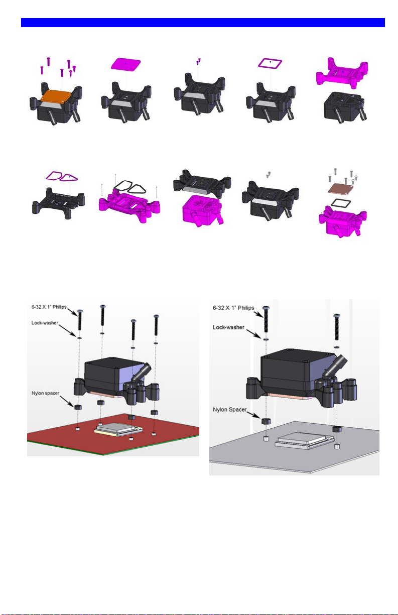
1. Apply the provided Arctic Céramique™
thermal grease at the center of the CPU as
shown above.
2. Peel-off the protective plastic film from the
Apogee™ Drive copper base plate, and wipeoff the copper with alcohol or with electronics
degreaser.
3. Fasten the Apogee™ Drive to the processor
by tightening all four screws progressively and
in a cross pattern until you reach a firm positive
lock. Cycle thru the four screws twice to make
sure that you have equal tension on all four.
77// EELLEECCTTRRIICCAALL CCOONNNNEECCTTIIOONNSS AANNDD PPRROODDUUCCTT UUSSAAGGEE
Apogee™ Drive connections
• Power: connect the 4-pin Molex
connector to your power supply.
• RPM sensor: connect the 3-pin single
wire connector to the motherboard
CPU fan header.
Critical recommendation:
Connecting the pump RPM sensor to the CPU fan
header is critical in order to monitor the pump.
Many modern motherboards have CPU fan safety
features that you can enable in the BIOS that will
shut down the power in the event of a CPU fan
failure or in this case in the event of a pump
malfunction.
Fan connections
• For 12V fan operations simply connect the 3-pin fan connectors to available motherboard fan
headers.
Page 6
Page 9

• For 7V fan operations connect the provided 12 to 7 volt adapter to the fans, and then connect
the adapters to available motherboard fan headers.
• For 5V fan operations connect the provided 12 to 5 volt adapter to the fans, and then connect
the adapters to the power supply. There is no fan speed monitoring in this configuration.
Note: many modern motherboards now have the ability to adjust the fan speed via the
motherboard BIOS, or under windows (nVidia® nTune for example). If you own such motherboard,
there is no need to use the 12 to 7 or 12 to 5V volt adapters.
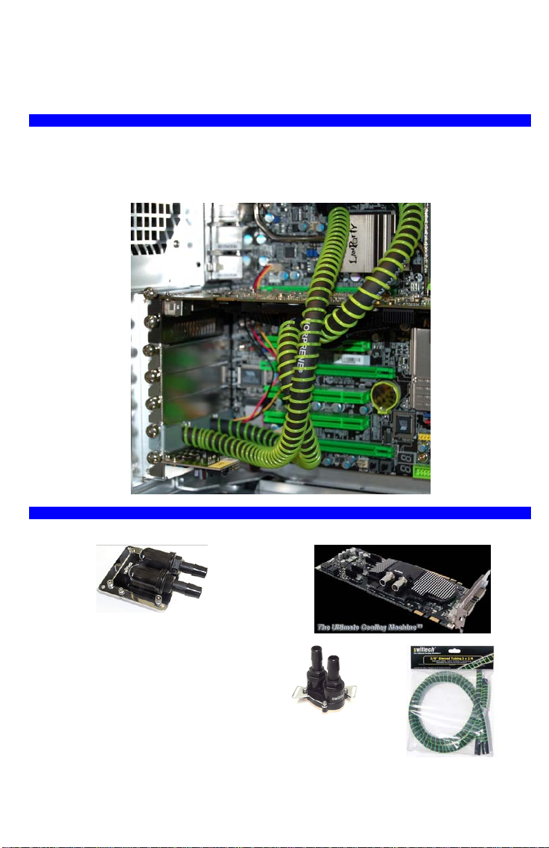
88// AADDDDIINNGG VVGGAA CCOOOOLLIINNGG && OOTTHHEERR DDEEVVIICCEESS TTOO TTHHEE CCOOOOLLIIN
The H20-220 Compact kit is an extreme cooling system capable of accommodating multiple waterblocks in the same loop such as VGA cards in SLI, and chipset coolers. Here is an example of tube
routing with a liquid cooled VGA card (using Swiftech Stealth)
NGG
LLOOOOPP
99// OOTTHHEERR SSWWIIFFTTEECCHH LLIIQQUUIIDD CCOOOOLLIINNGG PPRROODDUUCCTTSS ((PPLLEEAASSEE V
Do you need to cool your Graphics Card(s) too?
MCW60 universal VGA waterblock
Do you need to cool the chipset?
The MCW30 chipset Waterblock is the most
versatile of its kind on the market.
Do you need high performance tubing?
Swiftech uses Norprene®, the best lab-grade
tubing for water-cooling due to its low porosity.
Stealth for nVidia high-end 8800 series
Page 7
VIISSIITT
WWWWWW..SSWWIIFFTTEECCHH..CCOOMM))
Page 10
1100// SSUUPPPPLLEEMMEENNTTAALL AAMMDD®® IINNSSTTAALLLLAATTIIOONN GGUUIIDDEE
a/ Apogee Drive conversion from Intel Socket 775 to AMD Universal housing
1. Remove and
set aside all 6
screws as
shown above.
2. Remove and
set aside the
copper baseplate.
6. Remove the
o-rings from the
socket 775
…and install
them to the AMD
housing.
housing …
b/ Installation on the motherboard
3. Remove and
set aside the 2
internal screws
6. Place the
AMD housing
onto the Apogee
Drive body.
4. Remove and
set aside the
base-plate oring.
7. Fasten the 2
internal screws
5. Remove the
socket 775
housing.
8. Install o-ring,
base plate, and
fasten all 6
screws.
Socket AM2
Socket 754/939/940, and F
Page 8
Page 11
Guide D’installation
Introduction
Félicitations pour votre achat du kit Swiftech™ H20-220 COMPACT ! Bien que ce guide ait été
conçu pour faciliter au mieux l’installation du produit, il s’adresse à l’utilisateur avisé en matière
d’installation de composants électroniques.
Généralités
Il est conseillé de lire ce document dans sa totalité avant de commencer l’installation.
Débrancher le PC du secteur afin d’éviter tout risque de court-circuit lors du montage des
La prise ATX de la carte mère doit être débranchée lors de l’installation du système de
Assurez-vous toujours de tester le circuit pour toutes fuites éventuelles avant de remettre les
De quoi aurai-je besoin et qui n’est pas inclus avec ce kit?
• ½ Litre d’eau distillée pour faire le
mélange (usage obligatoire)
• Un testeur d’alimentation (ou tout
simplement un trombone) pour démarrer
l’alimentation.
• De l’alcool ou un dégraissant pour
composants électroniques.
11// IINNTTRROODDUUCCTTIIOONN
Voici une installation typique de refroidissement liquide du CPU. L’adaptateur ‘’Radbox’’ facilite
l’intégration du radiateur dans la plupart des circonstances grâce à l’installation au dos du boîtier,
ce qui optimise la performance thermique tout en laissant le passage pour tous les câbles I/O.
composants.
refroidissement.
composants électroniques en service !
H20-220 Compact
• Une paire de ciseaux pour couper les tuyaux
• Un tournevis cruciforme
• Une pince à becs
• Une douille de 14mm pour serrer les
embouts (de préférence, mais pas
obligatoire)
Apogee
Drive
Radiateur
“Radbox”
Page 9
Page 12
22// OOPPEERRAATTIIOONNSS PPRREEAALLAABBLLEESS
Pour les systèmes AMD®, l’Apogee™ Drive est pré configuré pour cartes mères Intel® socket 775.
Veuillez vous référer au guide supplémentaire pour AMD® (page 16) avant de continuer ci-après.
SYSTEMES INTEL®
Retirez le papier protecteur de l’autocollant au
dos de la plaque de renforts et installez celle-ci
au dos de la carte mère. Réinstallez ensuite la
carte mère dans le boîtier selon les instructions
du constructeur.
33// IINNSSTTAALLLLAATTIIOONN DDEE LL’’AADDAAPPTTAATTEEUURR RRAADDBBOOXX EETT DDUU RRAADDIIAAT
Installation de l’adaptateur Radbox
Utilisez les trous de montage du ventilateur existant afin d’accrocher la Radbox au dos du boîtier.
Le ventilateur existant peut rester en place. Il suffit simplement de remplacer les vis par celles
fournies dans votre kit. Nous présentons ci-dessous une installation sur un ventilateur de 120mm.
Le Radbox est aussi prévu pour 92, 80 ou même 60mm comme indiqué plus loin.
Mélangez la bouteille de HydrX fournie à ½ litre
d’eau distillée.
TEEUURR
1. Insérez les vis fournies au travers du
ventilateur et du boîtier, et vissez les
entretoises en nylon
2. Placez le support de boîtier sur les vis, et
serrez les écrous sans oublier les rondelles !
Page 10
Page 13
Dans les boîtiers utilisant des ventilateurs de 92, 80 ou même de 60mm, le support peut être ajusté
Préparation du radiateur
comme indiqué ci-dessus.
1. vissez les embouts au radiateur en utilisant
une douille de 14mm. N’oubliez pas les joints
toriques ! Serrez les embouts fermement.
44// IINNSSTTAALLLLAATTIIOONN DDUU SSYYSSTTEEMM DDEE RREEFFRROOIIDDIISSSSEEMMEENNTT
Afin de mesurer la longueur des tuyaux, l’ Apogee™ Drive sera tout d’abord montée
temporairement, ensuite démontée afin de remplir le system et enfin remontée de façon
permanente.
Note: il n’y a que deux orientations possibles pour l’ Apogee™ Drive, comme indiqué ci-après.
Position A Position B
2. Installez les ventilateurs, grille de protection
et boîtier Radbox comme indiqué ci-dessus en
utilisant seulement les vis de 30mm de long qui
vous sont fournies sous peine d’endommager
les canalisations du radiateur.
Page 11
Page 14

1. Enfoncez les tuyaux sur les embouts de l’ Apogee™ Drive et fixez-les avec les serre-joints
fournis. Serrez soigneusement à fond comme indiqué dans l’encart afin d’éviter les fuites.
2. Installez l’ Apogee™ Drive sur le CPU, sans
serrer les vis à fond.
4. Faites passer le tuyau par le slot PCI le plus
directement en face des embouts du radiateur.
Recoupez le tuyau seulement si nécessaire. Il
est préférable d’avoir du mou dans les tuyaux
afin qu’ils ne se pincent pas.
3. Accrochez l’assemblage Radiateur/Radbox
sur le support et serrez les 4 vis fournies.
5. Enfoncez les tuyaux sur les embouts
radiateur : tuyau de sortie Apogee™ Drive
(OUT) vers tuyau d’entrée (IN) du radiateur
comme indiqué ci-dessus, et vice versa.
Page 12
Page 15

6. Serrez les colliers de serrage bien à fond
comme indiqué dans l’encart afin d’éviter les
fuites.
55// RREEMMPPLLIISSSSAAGGEE EETT TTEESSTT DDUU SSYYSSTTEEMM DDEE RREEFFRROOIIDDIISSSSMMEENNTT
Mise en place
7. Insérez le braquet PCI dans le slot, fixez le,
et finalement faites passez les prises des
ventilateurs par l’œillet caoutchouc.
a/ Démontez l’Apogee Drive de la carte mère, et posez le à plat sur votre table de travail;
connectez la prise de la pompe Apogee à votre alimentation comme indiqué ci-dessus.
b/ Il est nécessaire de faire tourner la pompe afin de procéder au remplissage et au test du
système de refroidissement. Ceci requiert de pouvoir allumer l’alimentation sans qu’elle ne soit
branchée à la carte mère, ce qui n’est pas possible sans la manipulation décrite ci-après.
On peut utiliser l’interrupteur de l’alimentation en connectant la broche 14 de la prise ATX (fil vert)
à un fil de terre (noir) à l’aide d’un simple trombone. En raison des risques d’erreurs par les
utilisateurs qui pourraient résulter en dommages matériels ou corporels, nous recommandons à la
Page 13
Page 16

place de la méthode ci-dessus l’utilisation d’un testeur d’alimentation (mot clef google: ‘’ testeur
d’alimentation’’).
Green
14
Black
c/ Remplissez le radiateur à ras bord (sans déborder) et allumez l’alimentation (à noter que la
pompe de l’Apogée Drive à un délai de 3 secondes). Dès que la pompe démarre, vous entendrez
clairement la pompe gargouiller bruyamment en raison du mélange d’air et d’eau qui circule
rapidement à l’intérieur. En quelques secondes, le bruit se régularisera à un bourdonnement léger,
indiquant que le liquide circule normalement. Vous pouvez vérifier que le liquide circule en
regardant la légère agitation de surface par le trou de remplissage du radiateur. Ne vous inquiétez
pas si il y a de la mousse au départ, c’est normal. Elle disparaîtra au bout de 15 à 20 minutes.
Remettez le liquide de refroidissement à niveau, et laissez tou rner le système au moins une
heure (ou plus si vous le désirez) en prenant soin d’inspecter les fuites éventuelles.
Contrôlez et ajustez le niveau de liquide une dernière fois, et fermez le bouchon de remplissage
fermement afin d’éviter les fuites.
66// IINNSSTTAALLLLAATTIIOONN FFIINNAALLEE
1. Déposez une petite quantité de graisse
thermique Arctic Céramique™ sur le
microprocesseur.
2. Retirez le film protecteur de la base en cuivre
de l’Apogée Drive et nettoyez celle-ci avec de
l’alcool avant de l’installer.
3. Installez l’Apogée Drive sur le
microprocesseur. Serrez les vis graduellement
et en croix. Serrez fermement mais sans
excès, et faites deux passes en final afin de
bien sentir que la tension est identique aux 4
vis.
T
77// CCOONNNNEEXXIIOONNSS EELLEECCTTRRIIQQUUEESS EETT UUTTIILLIISSAATTIIOONN DDUU PPRROODDUUIIT
Connexions de l’Apogee™ Drive
• Puissance : connectez la prise Molex 4
broches à l’alimentation.
• Compte-tours : connectez la prise 3
broches (1 seul fil) à l’emplacement de
la carte mère réservé au ventirad.
Conseil Important :
Connecter la prise de compte-tours à la prise
ventirad de la carte mère est d’une importance
critique! Toutes les cartes mères modernes sont
équipées d’utilitaires de surveillance qui éteignent
le PC en cas de panne du système de
refroidissement. Bien contrôler le fonctionnement
de cet arrêt d’urgence !
Connexions du ventilateur
• Pour utiliser les ventilateur à 12 v (pleine puissance) simplement connecter la prise 3 broches
de chaque ventilateur à une prise 3 broches de la carte mère.
• Pour utiliser les ventilateurs à puissance réduite (faible niveau sonore), branchez l’adaptateur
12v à 7v fournis avec le kit sur chaque ventilateur, et branchez ceux-ci sur des prises
disponibles de la carte mère.
• Pour utiliser les ventilateurs en fonctionnement complètement silencieux, branchez
Page 14
Page 17
l’adaptateur 12v à 5v sur chaque ventilateur, et branchez ceux-ci sur des prises de puissance
de l’alimentation. On perdra le compte-tours du ventilateur dans cette configuration.
Conseil pratique : de plus en plus de carte mères modernes sont dotées d’utilitaires qui permettent
de régler la puissance du ventilateur dans le BIOS et même sous Windows (nTune par exemple).
Dans ce cas, les adaptateurs de puissance des ventilateurs ne seront pas nécessaires.
88// IINNTTEEGGRREERR LLEE RREEFFRROOIISSSSEEMMEENNTT GGRRAAPPHHIIQQUUEE ((EETT//OOUU CCHHIIPPS
Le kit H20-220 compact est un system de refroidissement extrême, parfaitement capable
d’absorber la charge thermique supplémentaire générée par des cartes graphiques en SLI et du
chipset. Nous présentons ci-après un exemple installation comprenant une carte graphique
refroidie par le water-block Swiftech Stealth.
SEETT))
AAUU SSYYSSTTEEMMEE
99// AAUUTTRREESS PPRROODDUUIITTSS DDEE RREEFFRROOIIDDIISSSSEEMMEENNTT LLIIQQUUIIDDEE SSWWIIFFT
Voulez-vous aussi refroidir la carte graphique ?
MCW60 waterblock VGA Universel
Voulez-vous aussi refroidir le chipset?
Le block de refroidissement liquide MCW30
est parmi les plus versatiles sur le marché.
Il vous faut du tuyau de haute
performance ?
Swiftech utilise Norprene® de St Gobain pour
son faible taux de porosité.
Stealth pour nVidia 8800 haut de gamme (GTX)
MCW30
Page 15
TEECCHH
((wwwwww..sswwiifftteecchh..ccoomm))
Page 18

1100// GGUUIIDDEE DD’’IINNSSTTAALLLLAATTIIOONN SSUUPPPPLLEEMMEENNTTAAIIRREE PPOOUURR AAMMDD®®
a/ Conversion de l’Apogée Drive du format socket 775 au format multiple pour AMD
1. Devissez les 6 vis
du socle comme cidessus.
6. Retirez les joints
toriques de la demi
coque 775, et…
b/ Installation sur la carte mère
2. Retirez la
plaque en
cuivre
réinstallez-les
sur la demi
coque AMD
3. Dévissez les 2
vis internes
7. Mettez la demi
coque AMD en
place
4. Retirez le
joint torique
8. Vissez les 2
vis internes
5. Retirez la
demi coque
plastique 775.
9. Réinstallez
joint torique et
plaque en cuivre
Socket AM2
Page 16
Socket 754/939/940, and F
Page 19

Montageanleitung
Einleitung
Glückwunsch und vielen Dank für den Kauf des H20-220 COMPACT Komplettsets von
Swiftech® . Die Installation des Systems ist bestimmt für die erfahrenen Benutzer, die gut die
Computer Komponente installieren können.
Empfehlungen
Bevor Sie die Installation beginnen, lesen Sie bitte sorgfältig die ganze Montageanleitung.
Als Sie das Komplettset installieren, schalten Sie dem Computer aus, um einen Kurzschluss
zu vermeiden.
Als Sie das Flüßigkühlsystem installieren, müssen Sie das Atx Stecker auschalten.
Bevor sie den Computer starten, kontrollieren Sie immer, dass Sie keine Leck haben!
Was brauche ich und was wird in dem Komplettset nicht geliefert?
• ½ Liter distilliertes Wasser (Sie müssen es
mit HydrX mischen).
• Netzteil Testgerät (oder einfacher eine
Büroklammer), um das Netzteil zu starten.
• Ein bisschen Alkohol um die Komponente
zu putzen.
1/ EINLEITUNG
Das Foto zeigt eine Installation von dem neuen CPU Komplettset.
Mit dem « Radbox », können Sie meisten Radiatoren auf die hintere Seite von dem Gehäuse
installieren.
Außerdem optmiziert das Radbox die thermischen Leistungen und haben Sie mehr Platz für die
ganzen Kabeln I/O
H20-220 Compact
• Eine Schere um die Schläuche zu schneiden
• Ein Kreuzschlitzschraubendreher
• Eine Flachzange
• Ein Stecknusssatz (14 mm).
Radiator
Page 17
Apogee
Drive
“Radbox”
Page 20

2/ VORHERIGE VORBEREITUNGEN
AMD® Systems: l’Apogee® Drive wird für Intel® Motherboards (Sockel 775) vormontiert. Mit
AMD® müssen Sie die Befestigung Platte ändern (Die Installation wird Seite 12 erklärt). Wenn es
fertig ist, folgen Sie den nächsten Etappen.
SYSTEMES INTEL®
Sie schälen das Schutzpaper auf die
Befestigungplatte und Sie installieren sie an der
Rückseite des Motherboards. Dann installieren
Sie wieder das Motherboard im Chassis (Sie
folgen den Anleitungen von dem Hersteller).
3/ RADBOX UND RADIATOR INSTALLATION
Radbox Installation
Sie benutzen die Löcher von dem Gehäuse (Löcher für das Lüfter), um das Radbox abzuhangen.
Es ist nicht nötig, das Lüfter zu entfernen.
Sie tauschen die Schrauben von dem Lüfer mit diesen von dem Koplettset aus.Das Foto zeigt eine
Installation mit einem Lüfter 120 mm.
Aber die Installation ist möglich mit anderen Lüfter (92, 80 oder 60 mm).
Sie vermischen die HydrX Flasche und ½ L
destilliertes Wasser.
1. Sie installieren die gelieferten Schrauben
durch den Lüfter und das Gehäuse und
schrauben die Distanzscheiben.
2. Sie installieren die Platte von dem Radbox
auf den Schrauben und sie ziehen die Mutter
an, ohne die Scheiben zu vergessen!
Page 18
Page 21

Mit den Lüfters 92mm, 80mm oder 60, können Sie die Platte einrichten.
Radiator
1. Sie installieren die Fittinge in den Löcher
des Radiators.
Vergessen Sie nicht die Dichtungsringe !
Drehen Sie mit dem Stecknasssatz die Fittinge
fest.
4/ INSTALLATION VON DEM FLÜßIGKÜHLSYSTEM
Um die Länge den Schläuche zu scheren, ist es nötig, die Komponente im Chassis zeitweise zu
installieren. Achtung! es ist temporarisch, bitte schrauben Sie nicht zu viel!
Anmerkung: das Apogee Drive kann in 2 verschiedenen Positionen orientiert werden. (wie aus den
beiden Fotos nachfolgend)
2. Sie installieren die Lüftergitter, die Lüfter,
das Gehäuse radbox (wie aus dem Foto
ersichtlich).
Passen Sie auf!
benuzten sie unbedingt die gelieferten
Schrauben (30 mm), sonst würden Sie die
Rohre des Radiators bohren.
Position A Position B
Page 19
Page 22

• 1. Sie schließen die Schläuche an die Fittings von Apogee® Drive an und Sie befestigen sie
mit den gelieferten Schlauchschellen. Sie drehen sorgfältig die Schlauchschellen mit der
Flachzange fest.
2. Sie installieren das Apogee™ Drive auf der
CPU und sie befestigen 2 Schrauben (nicht zu
viel). (es ist besser, dass es nicht bewegt!).
3. Sie hängen Radiator/radbox an die Platte an
und sie schrauben die 4 geliferten Schrauben.
4. Sie installieren die Schläuche durch den PCI
–Slot (wenn es möglich ist, radiators Fittinge
vor den Schläuche).
Um die Schläuche nicht zu knicken, brauchen
Sie genug Schlauch.
Page 20
5. Sie schließen den Schlauch an die Fittinge
von dem Radiator an :
Ausgabe von dem Apogee Drive (OUT) an
->die Eingabe von dem Radiator (IN)
Eingabe von dem Apogee Drive an -> die
AUSGABE von dem radiator.
Page 23

6. Sie befestigen die Schläuche mit den
gelieferten Schlauchschellen. Sie drehen
sorgfältig die Schlauchschellen mit der
Flachzange fest.
5/ FÜLLEN UND TESTEN DAS FLÜßIGKÜHLSYSTEM
Einbau
7. Sie fügen die Halterung PCI in den Slot ein ,
befestigen Sie sie und schließlich führen Sie die
Lüfterstecker durch die Gummitülle.
a/ Das Apogee Drive wird ausgebaut und gestellt auf den Tisch. Der Stecker von Apogee Drive
wird an das Netzeil angeschlossen. (wie aus dem Foto ersichtlich).
b/ Um das System zu füllen und zu kontrollieren, muss die Pumpe funktionieren. Sie müssen das
Netzteil starten. Aber, das Netzteil soll nicht an das Motherboard angeschlossen sein deshalb,
schlagen wir 2 Lösungen vor:
Page 21
Page 24

Wenn Sie anfänger sind, ist es besser diese Lösung zu wählen: Sie kaufen einen Netzteil
Testgerät (suchen mit Google: „Netzteil Testgerät“).
Für die Anderen: Sie können Pin 14 von dem ATX Stecker (im Allgemeinen ist es grün) an einem
Massekabel (schwarz) mit einer Büroklammer anschließen (aber es gibt Risikos).
Green
14
Black
c/ Sie füllen das Radiator, bis es voll ist (Überlaufen Sie den Radiator nicht). Sie starten das
Netzteil (der Apogee™ Drive wird 3 Sekunden später starten). Als Die Pumpe startet, hören Sie
den Lärm von der Kühlerflüssigkeit und der Luft, die sehr schnell in der Pumpe zirkulieren. Einige
Sekunden später, ist das Lärm leiser. Das bedeutet, dass alles in Ordnung ist! (keine Sorgern
wenn es Schäum gibt, es wird nach 15 Minuten verschwinden).
Sie füllen das System (wenn es nicht genug Kühlerflüssigkeit gibt) und lassen das System
während 30 Minuten bis 1 Stunde funktionnieren. Achtung ! Sie kon trollieren sorgfä ltig, dass
es keine Leck gibt.
Sie kontrollieren noch einmal das Stand von der Kühlerflüssigkeit (füllen notfalls) und sie Schließen
fest den Deckel. (um kein Leck zu haben).
6/ LETZTE INSTALLATION
1. 1. Sie tragen hauchdünn Warmleitpaste
auf CPU-Kern auf.
2. Sie schälen das Plastikschutz von der
3 Sie installieren das Apogee™Drive auf der
CPU. Befestigen Sie in Diagonal und
alternierend. (selbe Spannung für jede
Schraube).
Kupferplatte) (gezeigt rechte Foto). Bevor Sie
sie installieren, putzen Sie sie mit Alkohol.
7/ ANSCHLÜSSE UND DAS SYSTEM BENUTZEN.
Wie schließen Sie den l’Apogee® Drive
an?
• Leistung: Sie schließen den 4 Pins
Molex an das Netzteil an
• Drehzahler: Sie schließen das 3 Pins
Stecker an das Motherboards CPU
Lüfter Port an.
Es ist wichtig, das Sie das 3 Pins Stecker an das
Motherboards CPU Lüfter Port anschließen.
Die neuen Motherboards haben Hilfeprogrammen,
die den Computer aushalten, wenn das
Wasserkühlungsystem eine Panne hat.
Aber Sie müssen kontrollieren, dass dieses
Hilfeprogramm läuft.
Lüfter
• Um das Lüfter auf 12V (volle Leistung) zu benutzen, schließen Sie die 3 Pin Molex Anschluss
Page 22
Page 25

an die 3 Pin Motherboard Anschluss an.
• Um das Lüfter auf 7V (« quiet Power ») zu benutzen, schließen Sie das Adapter 12V auf 7V
(mit dem Komplettset geliefert) an den Lüfter und danach an den Motherboard Stecker.
• Um das Lüfter auf 5V (leise) zu benutzen, schließen Sie das Adapter 12V auf 5V an die Lüfter
an und dann schließsen Sie das Adapter an das Netzteil an. (aber sie lösen das
Drehzahlmesser von dem Lüfter).
Anmerkung: Die meisten Motherboards haben Programmen, die die Leistung des Lüfters in dem
BIOS regulieren (oder mit Windows auch, zum Beispiel: nVidia® nTune). Auf diesem Fall, ist das
Adapter unnötig.
8/ EIN GPU-GRAPHIKKARTENKÜHLER (UND/ODER CHIPSATZ KÜHLER) IN DEM
FLÛßIGKÛHLSYSTEM INTEGRIEREN
Das Komplettset H20-220 Compact ist ein extremes Flüßigkühlsystem und kann GPUgrafikkartekühler (eben für SLI Graffikkarte) oder/und Chipsatz Kühler integrieren.
Foto im Folgenden : H2O-220 Compact mit einer Graphikkarte wassergekühlt (Swiftech® Stealth:
unseres GPU-Grafikkartenkühler).
9/ SWIFTECH OPTIONEN (www.swiftech.com)
Die Grafikkarte kühlen ?
MCW60 grafikkartenkühler
Chipsatz kühlen?
Der Chipsatz-Kühler MCW30 ist sehr
vielseitig.
Page 23
Stealth für nVidia 8800 (GTX)
MCW30
Page 26

10/ MONTAGEANLEITUNG FÜR AMD® Sockel:
a/von Sockel 775 Befestigungplatte zu AMD® Befestigungplatte.
1. Sie bauen die 6
Schrauben aus.
2. Sie bauen
die
Kupferplatte
aus.
6. Sie bauen die
beide O rings von
der 775
Befestigungplatte
aus...
Und Sie
installieren sie
in der AMD®
Befestigungpl
atte.
b/ Installation auf dem Motherboard
3. Sie bauen die
2 Schrauben
7. Dann
installieren Sie
die AMD®
Befestigungplatt
e in dem Apogee
Drive® Körper.
4. Sie bauen
das O Ring
aus.
8. Sie
befestigen die
2 Schrauben.
5. Sie bauen die
Befestigungplatt
e (sockel 775)
aus.
9. Dann
installieren Sie O
Ring +
Kupferplatte und
befestigen die 6
Schrauben.
Socket AM2
Page 24
Socket 754/939/940, and F
Page 27

Guía de Instalación
H20-220 Compact
Introducción
¡Le agradecemos por haber comprado el kit Swiftech™ H20-220 COMPACT! Aunque esta guía
haya sido concebida para facilitar la instalación del producto, se dirige a usuarios enterados en lo
que se refiere a instalación de componentes informáticos.
Generalidades
Le aconsejamos leer atentamente este documento antes de empezar la instalación.
Desconectar el PC del sector para evitar cualquier riesgo de cortocircuito al instalar los
componentes.
El conector ATX de la placa base debe ser desconectado al instalar el sistema de
enfriamiento.
Asegúrese siempre de testar el circuito para detectar eventuales fugas antes de encender los
componentes electrónicos.
¿Qué voy a necesitar que no está incluido en este kit?
• ½ Litro de agua destilada para la mezcla
(uso obligatorio).
• Un testigo de fuente de alimentación (o
simplemente un clip) para encender la
fuente de alimentación.
• Alcohol o desengrasante para
• Un par de tijeras para cortar los tubos.
• Un destornillador cruciforme.
• Una pinza con puntas.
• Une boquilla de 14mm para apretar las
conteras (mejor, pero no obligatorio).
componentes electrónicos.
1/ INTRODUCCIÓN
Aquí está una instalación típica de enfriamiento líquido del CPU. El adaptador ‘’Radbox’’ facilita la
integración del radiador en la mayoría de las configuraciones gracias a una instalación en la parte
trasera de la caja, lo que optimiza la eficacidad térmica, mientras deja suficiente espacio para
todos los cables I/O.
Radiador
Page 25
Apogee
Drive
“Radbox”
Page 28

2/ OPERACIONES PREVIAS
El Apogee™ Drive está pre-configurado para las placas base Intel® socket 775. Si posee una
placa base AMD®, puede referirse a la guía suplementaria para AMD® (página 16) antes de
seguir con la instalación.
SISTEMAS INTEL®
Quitar el papel protector de la pegatina detrás
de la placa de refuerzos, e instalarla detrás de
la placa base.
Luego, vuelva a instalar la placa base en la caja
siguiendo las instrucciones del constructor.
3/ INSTALACIÓN DEL ADAPTADOR RADBOX Y DEL RADIATEUR
Instalación del adaptador Radbox
Utilice los huecos de montaje del ventilador para enganchar la Radbox detrás de la caja. El
ventilador puede quedarse en su sitio. Basta con sustituir los tornillos por los que están incluidos
en el kit.
Abajo le presentamos una instalación en un ventilador de 120mm. La Radbox también es
compatible con los de 92, 80 o incluso 60mm como indicado abajo.
Mezcle la botella de HydrX incluida en el kit
con ½ litro de agua destilada.
1. Insertar los tornillos incluidos a través del
ventilador y de la caja, y atornillar los tirantes
de nylon.
2. Coloque el soporte de la caja en los tornillos,
y apriete las tuercas, ¡sin olvidarse de las
arandelas!
Page 26
Page 29

Para las cajas que utilizan ventiladores de 92, 80 o incluso 60mm, el soporte puede ser ajustado
Preparación del radiador
1. Atornille las conteras al radiador utilizando
una boquilla de 14mm. ¡No se olvide de las
juntas! Apriete fuerte las conteras.
4/ INSTALACIÓN DEL SISTEMA DE ENFRIAMIENTO
Para medir la longitud de los tubos, el Apogee™ Drive será primero instalado de manera
temporaria, luego desinstalado y por fin re-instalado de manera permanente.
Nota: sólo existen dos orientaciones posibles para el Apogee™ Drive, como indicado abajo.
como indicado abajo.
2. Instalar los ventiladores, la rejilla de
protección y la caja Radbox como indicado
arriba, utilizando sólo los tornillos de 30mm
que están incluidos, o podría dañar las
canalizaciones del radiador.
Posición A Posición B
Page 27
Page 30

1. Clave los tubos en las conteras del Apogee™ Drive y fíjelos con los las abrazaderas incluidas
en el kit. Apriete fuerte como indicado en el esquema para evitar cualquier riesgo de fugas.
2. Instale el Apogee™ Drive en el CPU, sin
apretar mucho los tornillos.
4. Haga pasar el tubo a través del slot PCI lo
más alineado posible con las conteras del
radiador. Vuelva a cortar el tubo sólo si resulta
necesario. Es mejor dejarse un poco de
margen en los tubos para que no sean
demasiado apretados.
3. Enganche lo conjunto Radiador/Radbox en el
soporte y apriete los 4 tornillos incluidos.
5. Clave los tubos en las conteras del radiador:
tubo de salida Apogee™ Drive (OUT) hacia
tubo de entrada (IN) del radiador como indicado
arriba, y viceversa.
Page 28
Page 31

6. Apriete a fondo los collares de presión como
indicado en el encarte para evitar cualquier
riesgo de fuga.
5/ LLENADO Y TEST DEL SISTEMA DE ENFRIAMIENTO
Instalación
7. Inserte el bracket PCI en el slot, fíjelo y haga
pasar los conectores del ventilador por el
dispositivo de caucho.
a/ Desmonte el ’Apogee Drive de la placa base y póngalo en su mesa de trabajo, conecte el
conector de la bomba Apogee con su fuente de alimentación como indicado arriba.
b/ Es necesario que la bomba esté funcionando para empezar el llenado y los tests del sistema de
enfriamiento. Ello necesita poder encender la fuente de alimentación sin que esté conectada con
la placa base, lo que no resulta posible sin la manipulación descrita más abajo.
Se puede utilizar el interruptor de la fuente de alimentación conectando el pine 14 del conector
ATX (hilo verde) con un hilo de tierra (negro) utilizando un simple clip.
Page 29
Page 32

Para evitar los riesgos (daños materiales o corporales) que podrían surgir en caso de error por
parte del usuario, le recomendamos, en vez del método descrito arriba, utilizar un testigo de
alimentación.
Green
14
Black
c/ Llene al radiador para que se quede colmado (sin desbordarse) y encienda la fuente de
alimentación (la bomba del necesita un plazo de 3 segundos). En cuanto la bomba haya
arrancado, la oirá claramente gorgotear ruidosamente a causa de la mezcla de aire y de agua que
circula en el interior. Después de unos segundos, el ruido se hará mas leve, indicando que el
líquido está circulando normalmente.
Puede comprobar que el líquido circule mirando a la leve agitación en la superficie del agua por el
hueco de llenado del radiador. No se preocupe si ve espuma al principio, es normal. Desaparecerá
después de 15 o 20 minutos.
Vuelva a poner el líquido de enfriamiento a un nivel normal, y deje funcionar el siste ma por
lo menos dentro de 1 h (o más si quiere), comprobando que no hayan eventuales fugas.
Controle y ajuste el nivel de líquido por última vez, y cierre la tapa de llenado para evitar
eventuales fugas.
6/ INSTALACIÓN FINAL
1. Ponga una pequeña cantidad de grasa
térmica Arctic Cerámica™ en el
microprocesador.
2. Quite el film protector de la base de cobre
del Apogee Drive límpiela con alcohol antes de
instalarla.
3. Instale el Apogee Drive en el
microprocesador. Apriete los tornillos
gradualmente y en forma de cruz. Apriete fuerte
pero sin exceso, y haga dos pasajes más al
final para comprobar que la tensión esté
idéntica para los 4 tornillos.
7/ CONNEXIONES ELÉCTRICAS Y UTILIZACIÓN DEL PRODUCTO
Conexiones del Apogee™ Drive
• Potencia: conecte el conector Molex 4
pines con la fuente de alimentación.
• Cuenta giros: conecte el conector 3
pines (1 sólo hilo) en el sitio de la
placa base reservado para el ventirad.
Consejo Importante:
Conectar el conector del cuenta giros al conector
ventirad de la placa base es muy importante.
Todas las placas base modernas están equipadas
con utilitarios de vigilancia que apagan el PC en
caso de avería del sistema de enfriamiento. Tiene
que controlar el funcionamiento de esta parada de
urgencia.
Conexiones del ventilador
• Para utilizar los ventiladores en 12 v (potencia máx.) conecte simplemente el conector 3
pines de cada ventilador con un conector 3 pines de la placa base.
• Para utilizar los ventiladores con potencia reducida (nivel sonoro débil) conecte el adaptado r
12v a 7v incluidos en el kit de cada ventilador con conectores disponibles de la placa base.
• Para utilizar los ventiladores en funcionamiento completamente silenciosos, conecte el
adaptador 12v A 5v con cada ventilador, y conecte los ventiladores con conectores de
Page 30
Page 33

potencia de la fuente de alimentación. Perderemos el cuenta giros del ventilador con esta
configuración.
Consejo práctico: la mayoría de las placas base modernas están equipadas con utilitarios que
permiten ajustar la potencia del ventilador en el BIOS e incluso bajo Windows (nTune por
ejemplo). En este caso, los adaptadores de potencia de los ventiladores no serán necesarios.
8/ INTEGRAR EL ENFRIAMIENTO GRÁFICO (Y/O CHIPSET) AL SISTEMA
El kit H20-220 compact es un sistema de enfriamiento extremo, perfectamente capaz de absorber
la carga térmica suplementaria generada por tarjetas gráficas en SLI y por el chipset.
Abajo presentamos un ejemplo de instalación incluyendo una tarjeta gráfica enfriada por el waterblock Swiftech Stealth.
9/ OTROS PRODUCTOS DE ENFRIAMIENTO LÍQUIDO SWIFTECH (www.swiftech.com)
¿También quiere enfriar la tarjeta gráfica?
MCW60 waterblock VGA Universal
¿También quiere enfriar el chipset?
El bloque de enfriamiento líquido MCW30
forma parte de los más versátiles del
mercado.
¿Necesita un tubo de alta calidad?
Swiftech utiliza Norprene® de St Gobain por
su débil tasa de porosidad.
Stealth para nVidia 8800 de alta gama (GTX)
MCW30
Page 31
Page 34

10/ GUÍA DE INSTALACIÓN SUPLEMENTARIA PARA AMD®
a/ Conversión del Apogee Drive del formato socket 775 al formato múltiple para AMD
1. Destornille los 6
tornillos del zócalo
como indicado
2. Quite la
placa de
cobre.
arriba.
6. Quite las juntas de
la media cáscara
775, y…
Vuelva a
instalarlos en
la media
cáscara AMD
b/ Instalación en la placa base
3. Destornille los
2 tornillos
internos.
7. Instale la
media cáscara
AMD.
4. Quite ka
junta.
8. Atornille los
2 tornillos
internos.
5. Quite la media
cáscara de
plástico 775.
9. Vuelva a
instalar la junta y
la placa de
cobre.
Socket AM2
Page 32
Socket 754/939/940, y F
Page 35

possible, Swiftech™ assumes no liability expressed or implied for any damage(s) occurring to your components
as a result of using Swiftech™ cooling products, either due to mistake or omission on our part in the above
instructions, or due to failure or defect in the Swiftech™ cooling products. In addition, Swiftech™ assumes no
liability, expressed or implied, for the use of this product, and more specifically for any, and all damages caused
by the use of this product to any other device in a personal computer, whether due to product failure, leak, and
electrical short, and or electro-magnetic emissions. WARRANTY: Our products are guaranteed for 12 months
from the date of delivery to the final user against defects in materials or workmanship. During this period, they will
be repaired or have parts replaced provided that: (I) the product is returned to the agent from which it was
purchased; (II) the product has been purchased by the end user and not used for hire purposes; (III) the product
has not been misused, handled carelessly, or other than in accordance with any instructions provided with
respect to its use. This guarantee does not confer rights other than those expressly set out above and does not
cover any claims for consequential loss or damage. This guarantee is offered as an extra benefit and does not
affect your statutory
rights as a consumer.
IMPORTANT ! Malgré tous nos efforts pour vous offrir un guide technique le plus explicite possible,
DISCLAIMER: While all efforts have been made to provide the most comprehensive tutorial
des erreurs ou omissions sont possibles. La Société Swiftech® ne pourra pas être tenue pour responsable pour
tous dommages survenus aux composants suite à l’utilisation des produits de refroidissement Swiftech®,
dommages dus à des erreurs ou oublis de notre part dans les instructions ci-dessus mais également dus à un
mauvais fonctionnement ou un défaut des produits Swiftech®. Les images utilisées ci-après ne sont pas
nécessairement contractuelles. GARANTIE : Nos produits bénéficient d’une garantie de 12 mois à partir de la
date d’achat, garantie couvrant les défauts de matériaux ou de fabrication. Pendant cette période, les produits
seront réparés ou remplacés si les conditions suivantes sont respectées : (I) le produit doit être retourné au
revendeur où il a été acheté; (II) le produit a été acheté et utilisé par l’utilisateur final, il n’a pas été loué ; (III) le
produit n’a pas été mal utilisé, manipulé sans attention ou sans respect des règles d’utilisation mentionnées.
Cette garantie ne confère pas d’autres droits que ceux clairement cités plus haut et ne couvre aucune demande
de dommages et intérêts. Cette garantie est offerte comme un extra et n’affecte pas vos droits statutaires de
consommateur.
WICHTIG: Trotz unseren Anstrengungen, um eine klare und verständliche Montaganleitung
vorzuschlagen, können sie trotzdem Fehler machen.Auf diesem Fall, übernimmt swiftech keinerlei Haftung für
Schäden, die durch den Einbau oder die Anwendung entstanden sind oder, die auf ein Vergessen in der
Montageanleitung, ein schlechtes Funktionieren, oder auf Defekten der swiftech Produkts anzurechnen
sind.Außerdem übernimmt Swiftech keinerlei Haftung für die Verwendung von diesem Produkt oder anderen und
für die Schäden, die von dieser Verwendung für eine andere Funktion verursacht werden, selbst wenn es Lecks,
Defekt, Kurschluss oder elektromagnetischen Emissionen ist. GARANTIE: Unsere Produkte sind mit Garantie
während 12 Monaten, die Garantie beginnt den Tag des Verkaufs, schält die Materialdefekten oder die Fertigung
aus. Durch dieser Periode, werden die Produkten repariert oder geändert, wenn Sie diese Bedingungen
einhalten : 1) : Geben Sie den Produkt zurück, wohin Sie ihn gekauft haben ; 2) der Produkt wird von dem
Verbraucher gekauft und angewendet, der hat ihn nicht vermietet ; 3) Der Produkt muss gut angewendet sein
(einhaltend die Montaganleitung)Die Garantie gibt Ihnen kein anderes Recht und schält keinerlei Haftung für
Schadenersatz aus. Sie ist geschenkt und ändert ihre Rechte als Verbraucher nicht.
posible, errores u omisiones peden surgir. La sociedad Swiftech® no será responsable para cualquier daño de
los componentes resultando de la utilización de los productos de enfriamiento Swiftech®, provocados por errores
u omisiones en las instrucciones arriba, io debidos a un funcionamiento incorrecto o a un defecto de los
productos Swiftech®. Las imágenes utilizadas no son contractuales. GARANTÍA: Nuestros productos se
benefician de una garantía de 12 meses a partir de la fecha de compra, garantía que cobra los defectos de
material o de fabricación. Durante este periodo, los productos serán reparados o sustituidos si osn conformes a
las condiciones siguientes: (I) el producto debe ser enviado al distribuidor donde ha sido comprado; (II) el
producto ha sido comprado y utilizado por el usuario final, no ha sido alquilado; (III) el producto ha sido utilizado
correctamente, manipulado con cuidado, respetando las reglas de utilización indicadas arriba. Esta garantía no
otorga más derechos que los mencionados arriba, y no cobra ninguna petición de daños y perjuicios. Esta
garantía está oferta como un extra y no afecta los derechos estatutarios del consumidor.
¡IMPORTANTE! A pesar de todos los esfuerzos para ofrecerle una guía técnica lo más explicita
Page 36

Swiftech
3700 Industry Ave., Suite 104
Lakewood, CA 90712
US TOLL FREE (888) 857-9438
T. (562) 595-8009
F. (562) 595-8769
www.swiftech.com
Help@swiftech.com
 Loading...