

Page 1

H
2
H
T
T
h
h
0--
2
err
e
0
m
m
1
1
o
o
2
0
2
ell
e
T
0
eccttrriicc
e
T
Q
UII
D
C
O
LLIIQ
These instructions are updated on a regular basis. Please visit our web site at
U
D
C
TUTORIAL & INSTALLATION GUIDE
http://www.swiftnets.com
O
OLLII
O
N
G KKIITTSS
N
G
Rouchon Industries, Inc., dbA Swiftech™ – 1703 E. 28th St, signal Hill, CA 90755, USA – T (562) 595-12009 – F (562) 595-8769 – All content
Copyright Swiftech 2004 – Last edited 9-11-04 – Subject to revision without notice - 1 of 37 -
Page 2

Packing List
Included components per applicable model:
H20-120-PT
Description Product
Intel Pentium 4 (socket 478)
Intel Pentium 4 (LGA775)
Product
Code
PT 1 MCW5002-PT thermoelectric water-
775T 1 MCW5002-775T thermoelectric
64T 1 MCW5002-64T thermoelectric
AT 1 MCW5002-AT thermoelectric water-
ALL 1
Qty Item Product
block, with (2) # 6 worm drive hose
clamps & gaskets
water-block with (2) # 6 worm drive
hose clamps & gaskets
water-block with (2) # 6 worm drive
hose clamps & gaskets
block with (2) # 6 worm drive hose
clamps & gaskets
MCR120-F radiator assy. incl. (1)
Radiator, (1) 120x120x25mm fan,
(4) 6-32 x 3/8 philips screws, (4)
snap-rivets, (2) ½” barbs, (2) # 6
worm drive hose clamps
□ H20-120-775T □ H20-120-64T □ H20-120-AT □
Code
PT
775T
Description Product
Code
AMDAthlon 64 (SOCKET 754, 939, 940)
AMDAthlon MP, XP (socket 462)
Qty Item
Code
ALL 1
ALL 1
ALL 1
ALL 1 6 Feet 1/2” ID Clearflex high quality vinyl
ALL 1
MCP650 12 Volts DC industrial pump
with retention screws, 2 ft each preinstalled inlet & outlet tubing (3/8” ID), (2)
# 6 worm drive hose clamps
MCRES-525 incl. (1) reservoir, (2) 3/8”
barbs, (1) port plug, (1) fill-cap, (4)
screws, (2) # 6 worm drive hose clamps
40” length Coolsleeves clear coils
tubing
2 oz bottle HydrX specially formulated
coolant
64T
AT
ALL 1 MCR120-FR complete radiator, fan
and "Radbox" assembly, with (1)
120x25mm fans rated at 72.4CFM
and 34dBA, (2) 1/2" barbs, 3 pin to
4 pin Molex adapter, (2) ½” copper
tubes for PCI pass thru, (6) # 6
worm drive hose clamps
ALL 1 S320-12 Kit, 25 Amps auxiliary
power supply with relay switch
harness
ALL 1
ALL 1 Luberex Dielectric grease
ALL 1 MG chemicals conformal coating spray
Céramique thermal grease
Rouchon Industries, Inc., dbA Swiftech™ – 1703 E. 28th St, signal Hill, CA 90755, USA – T (562) 595-12009 – F (562) 595-8769 – All content
Copyright Swiftech 2004 – Last edited 9-11-04 – Subject to revision without notice - 2 of 37 -
Page 3

TTaabbllee ooff ccoonntteennttss
I. TUBE ROUTING ......................................................................................................................................................................................................5
II. INSTALLATION OVERVIEW OF THE COOLING COMPONENTS ..................................................................................................................5
R
ADIATORS INSTALLATION................................................................................................................................................................................................5
MCP650 PUMP INSTALLATION .........................................................................................................................................................................................5
OTHERBOARD PREPARATION, AND WATER-BLOCK(S) INSTALLATION ................................................................................................................................5
M
MCRES-525
RESERVOIR INSTALLATION........................................................................................................................................................................... 5
POWER SUPPLY INSTALLATION .........................................................................................................................................................................................5
UTTING THE TUBING, & CONNECTING COMPONENTS ........................................................................................................................................................6
C
REPARING THE COOLANT ............................................................................................................................................................................................... 6
P
FILLING UP THE CIRCUIT ...................................................................................................................................................................................................6
INAL INSTALLATION ........................................................................................................................................................................................................ 6
F
III. DRAINING THE SYSTEM ..................................................................................................................................................................................8
IV. PERIODIC MAINTENANCE............................................................................................................................................................................... 8
V. APPENDIX: INDIVIDUAL COMPONENT INSTALLATION GUIDES ....................................................................................................................9
MCR120-F
1. I
2. B
MCB-120™ “R
OUSING / FAN & RADIATOR INSTALLATION .....................................................................................................................................................................11
H
MCP650
1. G
2. P
RADIATOR INSTALLATION GUIDE ......................................................................................................................................................10
NSTALLATION .....................................................................................................................................................................................................10
LEEDING........................................................................................................................................................................................................... 10
ADBOX” KIT INSTALLATION GUIDE ...........................................................................................................................................................11
PUMP INSTALLATION GUIDE.......................................................................................................................................................................... 12
ENERAL USE ....................................................................................................................................................................................................12
HYSICAL INSTALLATION .....................................................................................................................................................................................12
3. PUMP OPERATING PRECAUTIONS: ........................................................................................................................................................................12
ERFORMANCE & SPECIFICATIONS...................................................................................................................................................................... 13
4. P
ERMANENT INSTALLATION TO THE CHASSIS AND EXPLODED VIEW ........................................................................................................................ 13
5. P
MCRES-525™ RESERVOIR INSTALLATION GUIDE ..........................................................................................................................................................14
NSTALLATION GUIDELINES .............................................................................................................................................................................................15
I
S320-12
S320-12
POWER SUPPLY KIT INSTALLATION GUIDE ..........................................................................................................................................................16
1. S320-12 POWER SUPPLY INSTALLATION .............................................................................................................................................................. 16
ELAY SWITCH INSTALLATION .............................................................................................................................................................................17
2. R
OWER SUPPLY VENTILATION ..............................................................................................................................................................................17
3. P
MCW5002-775T™ T
REPARING THE MOTHERBOARD..........................................................................................................................................................................20
1. P
ONDENSATION CONTROL MEASURES..................................................................................................................................................................20
2. C
HERMOELECTRIC WATER-BLOCK INSTALLATION GUIDE FOR INTEL PENTIUM 4 (LGA775)........................................................... 19
3. ELECTRICAL INSTALLATION.................................................................................................................................................................................. 21
YDRAULIC INSTALLATION...................................................................................................................................................................................22
4. H
MCW5002-PT™ T
HERMOELECTRIC WATER-BLOCK INSTALLATION GUIDE FOR INTEL PENTIUM 4 (SOCKET 478) ........................................................23
1. PREPARING THE MOTHERBOARD..........................................................................................................................................................................24
ONDENSATION CONTROL MEASURES..................................................................................................................................................................24
2. C
LECTRICAL INSTALLATION.................................................................................................................................................................................. 25
3. E
4. HYDRAULIC INSTALLATION ...................................................................................................................................................................................26
MCW5002-AT™ T
ONDENSATION CONTROL MEASURES..................................................................................................................................................................29
1. C
LECTRICAL INSTALLATION.................................................................................................................................................................................. 31
2. E
YDRAULIC INSTALLATION...................................................................................................................................................................................32
3. H
MCW5002-64T™ T
ONDENSATION CONTROL MEASURES..................................................................................................................................................................34
1. C
LECTRICAL INSTALLATION.................................................................................................................................................................................. 36
2. E
YDRAULIC INSTALLATION...................................................................................................................................................................................37
3. H
HERMOELECTRIC WATERBLOCK INSTALLATION GUIDE FOR AMD ATHLON MP, XP, SEMPRON (SOCKET 462) .....................................28
HERMOELECTRIC WATER-BLOCK INSTALLATION GUIDE FOR AMD ATHLON 64, OPTERON (SOPCKET 754, 939, 940).........................33
Rouchon Industries, Inc., dbA Swiftech™ – 1703 E. 28th St, signal Hill, CA 90755, USA – T (562) 595-12009 – F (562) 595-8769 – All content
Copyright Swiftech 2004 – Last edited 9-11-04 – Subject to revision without notice - 3 of 37 -
Page 4

Preamble
Congratulations on your purchase of a Swiftech liquid cooling system!
This kit has been designed to facilitate the installation of the components with as few and simple modifications to the
chassis as possible. It is nonetheless intended for advanced users, well versed in installing computer components.
General guidelines
Never work with electricity connected to the computer while work is in progress.
The reservoir should always be at the highest point of the cooling circuit .
While it is possible to install the kit in a chassis already populated with all typical components, such as hard drive,
CD Rom, power supply, etc, it is always preferable and easier to work on a “naked” case, removing both side
panels, front bezel, and top panel.
Plan your installation ahead. Observe the relative position of the components for possible interference with other
components. Examples: will the pump interfere with a hard drive? Will the radiator interfere with the installation of
the CPU cooler?
Think about the airflow inside your chassis. In liquid-cooling environments, it is always better to draw fresh air from
the outside through the radiator, as opposed to using the warm air from inside the computer.
IMPORTANT DISCLOSURES
While all efforts have been made to provide the most comprehensive tutorial possible, Swiftech assumes no liability
expressed or implied for any damage(s) occurring to your components as a result of using Swiftech cooling products,
either due to mistake or omission on our part in the above instructions, or due to failure or defect in the Swiftech™
cooling products.
WARRANTY
Our products are guaranteed for 12 months from the date of delivery to the final user against defects in materials or
workmanship. During this period, they will be repaired or have parts replaced provided that: (I) the product is returned
to the agent from which it was purchased; (II) the product has been purchased by the end user and not used for hire
purposes; (III) the product has not been misused, handled carelessly, or other than in accordance with any
instructions provided with respect to its use. This guarantee does not confer rights other than those expressly set out
above and does not cover any claims for consequential loss or damage. This guarantee is offered as an extra benefit
and does not affect your statutory rights as a consumer.
Rouchon Industries, Inc., dbA Swiftech™ – 1703 E. 28th St, signal Hill, CA 90755, USA – T (562) 595-12009 – F (562) 595-8769 – All content
Copyright Swiftech 2004 – Last edited 9-11-04 – Subject to revision without notice - 4 of 37 -
Page 5

I. TUBE ROUTING
The following table contains examples on how to establish connections between the different elements of a cooling circuit This table assumes that the
reservoir is positioned at the uppermost position in the computer, and that the pump is located at the lowermost location.
These are guidelines only, and may change depending on the relative position of the components inside your chassis.
Devices: (1) CPU Cooler (2) Radiators + Pump + MCRES-525
Reservoir
discharge
to pump
inlet
Devices: (1) CPU Cooler (2) Radiators + Pump + MCRES-525 + VGA Cooler
Reservoir
discharge
to pump
inlet
Pump
discharge to
Radiator #1
inlet
Pump
discharge to
Radiator #1
inlet
Radiator #1
discharge
to radiator
#2 inlet
Radiator #1
discharge
to radiator
#2 inlet
Radiator #2
discharge to
CPU
Waterblock
inlet
Radiator #2
discharge to
VGA Inlet
CPU Waterblock
discharge to reservoir
inlet
VGA discharge to CPU
Waterblock inlet
Loop completed
CPU Waterblock
discharge to
reservoir inlet
Loop completed
II. Installation overview of the cooling components
The following is a typical sequence of components installation. Placement of the cooling components may vary depending on your chassis and
motherboard configurations. A mock-up installation is thus necessary to estimate the length of the different sections of tubing that will be required
between each component.
Motherboard preparation, and Water-block(s) Installation
MCRES-525 reservoir installation
This part of the installation is by and large the most crucial. Please
refer to your specific model of CPU cooler installation guide in the
appendix section to prepare your motherboard and install the
Waterblock.
Radiators installation
The H20-120T kit is supplied with two 120mm radiators. One radiator is
equipped with our MCB120 “Radbox” and should be installed externally
at the back of chassis. The second radiator/fan combo is meant to be
installed inside of the chassis, preferably in the front intake fan location.
Please refer to the MCB120 “Radbox”
schematics in the appendix pages for further installation details.
MCP650 Pump installation
Preferable position of the pump is at the bottom of the chassis. However,
the pump can operate in any position. For optimum safety, the pump can
be bolted to the chassis. TIP! Do not peel-off the protective sticker until
you are satisfied with the position of the pump, as subsequent removal is
destructive to the foam gasket.
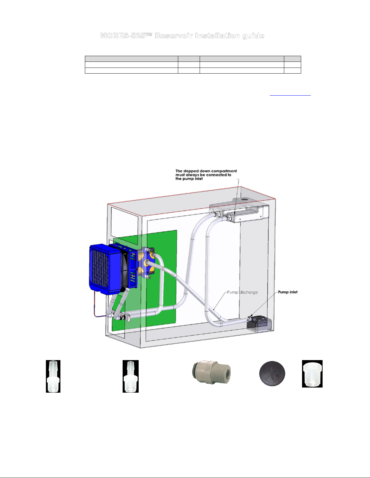
TIP! Identify the pump inlet and make sure to connect this tube to the
reservoir discharge barb (the single barb located on the stepped down
compartment of the reservoir). This is essential for proper operations.
Please refer to the complete installation guide
pages for further instructions.
and MCR120-F installation
located in the appendix
Install the MCRES-525 reservoir in the desired 5 ¼” bay, following
the installation guide
TIP! Positioning the reservoir at the highest point of the liquid
cooling circuit is preferred but not mandatory. If one of the
components, the radiator for example, is higher than the reservoir,
you may want to fill-up the reservoir outside of the chassis, holding
it above the radiator, and once done close the fill-cap, and secure
the reservoir in the desired bay.
TIP! Position the reservoir so that it protrudes approximately 1 ½”
outside of the case. Measuring the length of tube needed in this
position will give sufficient slack in the line so that you can pull the
reservoir enough to fill-it-up during maintenance operations.
Power Supply Installation
The S320-12 auxiliary power supply supplied with your kit fits in a
5 ¼” bay with the provided rails. Because it generates a significant
amount of heat, we recommend that it be installed in the
uppermost drive bay. To prevent it from overheating, a blowhole in
the top case panel located in the general vicinity of the power
supply exhaust vent is highly desirable.
Please refer to the complete installation guide
appendix pages for further instructions.
located in appendix.
located in the
Rouchon Industries, Inc., dbA Swiftech™ – 1703 E. 28th St, signal Hill, CA 90755, USA – T (562) 595-12009 – F (562) 595-8769 – All content
Copyright Swiftech 2004 – Last edited 9-11-04 – Subject to revision without notice - 5 of 37 -
Page 6

Cutting the tubing, & connecting components
Now that your mock-up installation is in place, it is time to cut segments of tubing and connect the devices together.
Preparing the coolant
Your kit comes with a 2 Oz (60ml) bottle of Swiftech’s specially formulated HydrX concentrated coolant. The product should be mixed with
distilled or demineralized water only. Simply empty the concentrated coolant into a 33 fl oz (1 liter) plastic bottle, and complete filling with your
distilled water. Your coolant is ready.
Filling up the circuit
Please refer to the MCRES-525 installation guide
measures.
It is good practice to pre-test that your system is liquid-tight away from sensitive electronic components. Two strategies can be employed:
Dismount all the components that you installed in the mock-up, and fill-up your system outside of the case, or
Remove Hard-drive(s), floppy, CD-ROM, VGA adapter, Memory, and any other add-on cards (Raid, sound, network, etc.), and
In either case, you will need to start-up your pump in order to completely fill-up the system. Since your MCP350 is a 12Volts pump feeding off
the computer power-supply, you must be able to start the PSU without it being connected to the motherboard. While the Internet is full of
references on how to short-out pin 14 and 15 of the ATX connector to start up the PSU independently, we really do not recommend this method.
The safe and proper method to start-up the PSU independently is to use a power-supply tester. A wide variety of these common devices is
available on the Internet (Google key word: “PSU tester”), and among Swiftech resellers (www.frozencpu.com
www.newegg,.com
Final installation
Once your system has been tested for leaks, it is now time to proceed with the final installation. Assuming that you followed our preferred
method, re-install all the components inside the chassis, being careful to keep the water-blocks out of the way (some wire-ties or rubber
bands strategically placed are a good help). Then perform the final water-block installation using thermal grease, in accordance with your
specific water-block model installation guide (see appendix).
in appendix for specifics on how to fill-up the system. In this paragraph, we will discuss safety
test with the motherboard installed in the chassis only. Make sure that the motherboard is not electrically connected (our
preferred method). If an accident happened, and fluid was sprayed onto the motherboard, clean off the moist area, use a can of
compressed air if available to blow the area dry (or a hair dryer), and wait 24 hours to let any moisture dry off.
, www.Directron.com,
etc..)
Rouchon Industries, Inc., dbA Swiftech™ – 1703 E. 28th St, signal Hill, CA 90755, USA – T (562) 595-12009 – F (562) 595-8769 – All content
Copyright Swiftech 2004 – Last edited 9-11-04 – Subject to revision without notice - 6 of 37 -
Page 7

Figure 1
Figure 1 above illustrates a typical CPU cooling installation. Notice the use of Coolsleeves in very tight bends to prevent the tubes from kinking.
Also note the position of the auxiliary power supply in the uppermost drive bay. Since this unit generates a significant amount of heat, a case
with a blowhole on the top panel is desirable to reduce the overall internal case temperature. Candidate case-modders may take this one step
further by adding a blowhole with a very slow (quiet) 80mm fan directly above the power supply vent. This will provide constant cooling to the
power supply, and prevent its’ 60mm fan overheating protection to quick in. The benefit is reduced noise, and prolonged life for the PSU.
We installed a blowhole in this chassis to provide adequate ventilation to the auxiliary power-supply.
Rouchon Industries, Inc., dbA Swiftech™ – 1703 E. 28th St, signal Hill, CA 90755, USA – T (562) 595-12009 – F (562) 595-8769 – All content
Copyright Swiftech 2004 – Last edited 9-11-04 – Subject to revision without notice - 7 of 37 -
Page 8

III. Draining the system
You will need to disconnect a line from one of the lowermost components. Procure a bucket large enough to receive approximately 1
liter of fluid, and place the bucket underneath the connection that you intend to “break”. Disconnect the line, and place both ends into
the bucket.
Open up the fill-cap from the MCRES-525. This will allow most of the fluid to escape.
A cleaner and much more convenient method consists in incorporating a drain assembly into the circuit during initial installation. See
drain assembly below.
TV500
IV. Periodic maintenance
Every 6 months: dust off the radiator fins and fan. You can use a can of compressed air for example, available in most
electronic supply stores. If you live in a very dusty area, you should perform this task at closer intervals. It is essential to
maintain the optimum performance of your cooling system.
Inspect the level of liquid inside the circuit, and refill if necessary. Evaporation in this closed circuit is extremely limited, but
still present due to permeability in the vinyl lines.
Rouchon Industries, Inc., dbA Swiftech™ – 1703 E. 28th St, signal Hill, CA 90755, USA – T (562) 595-12009 – F (562) 595-8769 – All content
Copyright Swiftech 2004 – Last edited 9-11-04 – Subject to revision without notice - 8 of 37 -
Page 9

V. Appendix: Individual Component Installation guides
- INTENTIONNALY LEFT BLANK -
Rouchon Industries, Inc., dbA Swiftech™ – 1703 E. 28th St, signal Hill, CA 90755, USA – T (562) 595-12009 – F (562) 595-8769 – All content
Copyright Swiftech 2004 – Last edited 9-11-04 – Subject to revision without notice - 9 of 37 -
Page 10

Packing list
MCR120 radiator 1 ½” barbs 2
Snap-rivet 4 120x25mm fan 1
6-32” x 3/8” Philips screw 4 #6 worm drive clamps 2
Front
of
Chassis
Snap-rivet
6-32 x 3/8" philips
120mm fan
MCR120 radiator
Figure 2 – Front of chassis installation
Preamble
The MCR120-F ships with the fan pre-assembled to the radiator. It has been configured so that the fan will draw fresh air from outside of the
chassis. This configuration is preferred to optimize cooling of the CPU. In effect, if the fan flow direction were reversed, it would use heated air inside
of the chassis, which is usually 3°C (at best) and up to 10°C hotter than that of the ambient air outside of the chassis.
1. Installation
In this kit, the preferred installation location of the MCR120-F is at the front of the chassis. Due to the wide variety of chassis configurations,
Swiftech cannot guarantee that this assembly will bolt into any chassis without some modifications.
2. Bleeding
For bleeding purposes, the preferred radiator orientation is with inlet and outlet pointing up as shown above. Nonetheless, the radiator can also be
installed at 90° or 180°. In such cases, simply rotate the radiator back upwards to allow the air trapped inside to escape during the filling and bleeding
process. For this reason, it might be more convenient to fasten the radiator to the chassis after the circuit has been fully filled and bled.
Specifications
Rouchon Industries, Inc., dbA Swiftech™ – 1703 E. 28th St, signal Hill, CA 90755, USA – T (562) 595-12009 – F (562) 595-8769 – All content
Radiator Assembly Dimensions - Part # MCR120-FB
Thickness Height Core width Inlet Outlet tube size
0.98"
(25mm)
Voltage
(V)
7.0-13.8 .20 2100 72.4 .134 34
Copyright Swiftech 2004 – Last edited 9-11-04 – Subject to revision without notice - 10 of 37 -
5.9"
(157mm)
Current
(mA)
5.00"
(133mm)
Speed
(RPM)
1/2" (tube OD) quick connect adapters included
Fan Specifications - Part # WFB1212M
Volume
(CFM)
Static pressure
(InH20)
Sound Noise
(dbA)
Page 11

Parts QTY PARTS QTY
MCB-120™ Housing assembly 1 ½” barbs 2
Retention hardware (screws, etc.) 1 # 6 worm drive clamps 6 (*)
½” copper tubes for PCI pass-thru 2
Housing / fan & radiator installation
reservoir
discharge
Pump inlet
Pump discharge
Chassis
MCB-120
holding plate
1/2" Nylon spacer (use as needed to provide clearance
with side panel) or alternatively use (1) or (2) provided nylon washers
6-32 x 1" machine screw (fine thread)
Use alternate 6-32 x 1 1/2" for thick acrylic panels
or provided 4-40 x 1 1/4" with nuts and washers for 60mm fan openings
#4 x 1/4"
sheet metal screw
nut
(course thread)
6-32 nylon
metal screw
(coarse thread)
#6 x 1 1/4" sheet
housing
MCB-120
fan
120x25mm
Radiator
Route tubes
thru a PCI slot
Rouchon Industries, Inc., dbA Swiftech™ – 1703 E. 28th St, signal Hill, CA 90755, USA – T (562) 595-12009 – F (562) 595-8769 – All content
Copyright Swiftech 2004 – Last edited 9-11-04 – Subject to revision without notice - 11 of 37 -
Page 12

1. General Use
The MCP650 pump is a magnetically driven
centrifugal pump featuring a 12 V DC motor. It
requires no maintenance when used with demineralized water and the appropriate anti-fungal
additives. We recommend using 5% Swiftech’s
HydrX as an additive. The pump is designed to be
connected to your computer power supply using the
standard Molex 4 pin connectors.
The MCP650 pump is not submersible.
2. Physical installation
Determine the best location for your pump by
observing how the tubing will be routed to the
rest of the circuit. Sharp bends in the tubing
should always be avoided to prevent kinks,
which will reduce or completely prevent flow of
the cooling fluid.
In general, we recommend installation of the
pump at the bottom of the chassis.
The base of the pump features a soft neoprene
pad coated with strong adhesive material. Once
an appropriate location for the pump has been
determined, simply peel-off the pad’s protective
paper, and press the pump against the chassis
surface. The surface should be clean, and non
greasy. Thru-bolts are also provided for
permanent installation, and require drilling holes
in the chassis (see permanent installation page
2).
3. Pump operating precautions:
The MCP650 pump should never be run dry, even
for a quick test. You should always prime the pump
with fluid before you start operating it (see warranty
note *).
Use of coloring die or fluorescent additives
containing particulate fillers will cause excessive wear
to the pump’s impeller bearing (see warranty note **).
Rouchon Industries, Inc., dbA Swiftech™ – 1703 E. 28th St, signal Hill, CA 90755, USA – T (562) 595-12009 – F (562) 595-8769 – All content
Copyright Swiftech 2004 – Last edited 9-11-04 – Subject to revision without notice - 12 of 37 -
Page 13

4. Performance & Specifications
WARRANTY: This product is guaranteed for a period of 24 months from date of purchase for defects in material, and workmanship.
Guarantee consists of replacing defective parts with new or reconditioned parts. Guarantee is considered void in case of improper use
(*)(**)(***), handling or negligence on the part of user. Original invoice showing date and place of purchase is required for exercise of the
warranty.
EXCESSIVE WEAR DUE TO INNAPROPRIATE FLUIDS. (***) EXCESSIVE RESTRICTION TO THE PUMP’S INLET
(*) WARNING: DO NOT ATTEMPT TO RUN THIS PUMP DRY. THIS WILL CAUSE IMMEDIATE AND PERMANENT DAMAGE TO THE PUMP. (**)
Nominal voltage 12 V DC
Operating voltage range 6 to 14 VDC
Nominal power (@ 12 V) 24 W
Nominal current (@ 12 V) 2 amps
Motor type
Maximum head 10 ft (3.1 m)
Maximum discharge ~ 317 GPH (1200 LPH)
Connection size ½" barbs
Maximum pressure 50 PSI (3.5 BAR)
Temperature range 32 °F to 140°F (0 °C to 60 °C)
Electrical connector Molex 4 pin
Weight 1.4 LB (650 gr.)
Impeller Housing material Noryl®
Our noise measurement (non
lab environment)
Brushless, microprocessor
controlled
33 ~ 34 dBA in a quiet room @ 2'
DISCLAIMER: Swiftech assumes no liability whatsoever, expressed or implied, for the use of this product, and more specifically for
any, and all damages caused by the use of this product to any other devices in a personal computer, whether due to product failure,
leak, electrical shorts, and or electro-magnetic emissions.
5. Permanent installation to the chassis and exploded view
Rouchon Industries, Inc., dbA Swiftech™ – 1703 E. 28th St, signal Hill, CA 90755, USA – T (562) 595-8009 – F (562) 595-8769 – All
content Copyright Swiftech 2004 – Last edited 9-27-04 – Subject to revision without notice - 13 of 37 -
Page 14
PARTS LIST – BARBED ADAPTERS ARE SOLD SEPARATELY
Parts QTY PARTS QTY
MCRES-525™ Reservoir 1 Retention screws 4
This product is intended for expert users. Please consult with a qualified technician for installation. Improper installation may result in
damage to your components. Swiftech assumes no liability whatsoever, expressed or implied, for the use of these products, nor their
installation. The following instructions are subject to change without notice. Please visit our web site at www.swiftnets.com
updates.
The MCRES-525™ reservoir is designed to be installed in a 5 ¼” drive bay. It features three 3/8” threaded ports (standard NPT thread)
to accommodate a number of configurations (see * Swiftech fittings). The port usage is defined as follows:
The following guide assumes that all liquid cooling components in your system, such as radiator, pump, and water-block(s) have been
already installed, and the graphic below shows an overview of a typical installation.
Fill-cap & o-ring 1 Port plug 1
for
(1) Discharge port located at the “stepped-down” compartment. This port must ALWAYS be connected to the
pump inlet for the MCRES-525™ to operate properly.
(2) Inlet ports can be used interchangeably: in “single inlet” configuration (the most common), or “dual inlet”
configuration when devices are returning to the reservoir in parallel. One port plug is provided to seal one of the
inlets in order to accommodate the most common “single inlet” configuration.
Important! All fittings (except DP-11) require sealant: plumbers tape, or plumbers goop (preferred)
A6-8
1/2" barb to 3/8" NPT, for 1/2"
Inner diameter tubing (3/4" or
5/8" outer diameter) – Order
Separately
Rouchon Industries, Inc., dbA Swiftech™ – 1703 E. 28th St, signal Hill, CA 90755, USA – T (562) 595-8009 – F (562) 595-8769 – All
content Copyright Swiftech 2004 – Last edited 9-27-04 – Subject to revision without notice - 14 of 37 -
A6-6
3/8" barb to 3/8" NPT, for
3/8" Inner diameter tubing
(1/2"outer diameter) – Order
separately
Swiftech Fittings & Spare parts
PI011623S
3/8” NPT to ½” tube (outer
diameter) quick-connect
fitting – Order separately
DP-11
Fill-cap & o-ring
Included
P6N
3/8” NPT Port
plug
Included
Page 15

Installation guidelines
Figure 1: Always leave sufficient slack in the lines to pull enough
of the reservoir out of the drive bay and uncover the fill port.
Figure 2: You can start filling up the reservoir while it is in the drive
bay, using a household funnel. Then, start-up the pump and top-off
the reservoir as needed. With this method, you will be able to fill-up
the reservoir to its minimum operating level, as shown figure 3.
Figure 3: The minimum operating fluid level is at the mould
parting line.
Figure 5: Desired (Maximum) operating fluid level Figure 6: Once full, secure the reservoir to the drive-bay with the
Figure 4: If possible or desired, you can also fill the reservoir outside
of the chassis. Tipping it steeply at an angle will allow you to fill-it up at
the maximum operating level as shown figure 5. Do not forget to close
the fill-cap before you re-install the unit into the drive bay!
provided screws. Installation is complete!
Rouchon Industries, Inc., dbA Swiftech™ – 1703 E. 28th St, signal Hill, CA 90755, USA – T (562) 595-8009 – F (562) 595-8769 – All content
Copyright Swiftech 2004 – Last edited 12-9-04 – Subject to revision without notice - 15 of 37 -
Page 16

S320-12
Qty Item
1 S320-12 power supply installed in 5 ¼” adapter tray, screws
1 Electrical harness
1 Relay Switch
1 A/C socket adapter, stainless steel cover plate, screws
1 A/C cord
1 80mm fan guard with (4) snap rivets
Preamble
This kit has been designed to facilitate installation with as little modifications to the case as possible. It is however meant for advanced users, well
versed in installing computer components.
This kit includes (Check-marked for applicable model and content):
Specific tools needed to complete the
installation:
• Power drill
• 1 ¼” (32mm) Bi-Metal hole saw to drill hole
for A/C socket
• 1/8” (3.17mm) Drill bit for A/C socket cover
mounting holes
• Optionally: 3 ¼” Bi-Metal hole saw to drill
an 80mm blow hole above the power
supply fan exhaust
General Rules:
1. Always work on a “naked” case, removing side panels, front bezel, and top panel, with no power supply installed.
2. Never work with electricity connected to the computer while work is in progress.
3. Strip the case “naked”: Since you will be making holes in the case, metal debris could be flying off into your components, and a “naked”
chassis will be easier to clean-up.
1. S320-12 Power supply installation
Install the power supply in a 5 ¼” bay, preferably in the uppermost slot as shown in figure 1. Use the provided screws to secure tray to the chassis.
Figure 3
Rouchon Industries, Inc., dbA Swiftech™ – 1703 E. 28th St, signal Hill, CA 90755, USA – T (562) 595-8009 – F (562) 595-8769 – All content
Copyright Swiftech 2004 – Last edited 12-9-04 – Subject to revision without notice - 16 of 37 -
Page 17
2. Relay Switch Installation
Find a suitable placement to drill a hole for the A/C socket adapter.
Leave sufficient room under or above the hole to install the relay
switch circuit board. A ¼” minimum clearance will be required
between the circuit board and the edge of the hole.
Make a 1.25” (32mm) diameter hole in the case, using a 1 ¼” Bi-
Metal hole saw. Deburr the edges of the hole with sand paper.
Position and center the mounting plate over the hole as a template to
mark the locations of the plate’s mounting screws. Drill 2 holes of
.125” diameter for the mounting screws.
Install the mounting plate using the screws provided with your kit.
Insert the A/C socket inside the mounting plate.
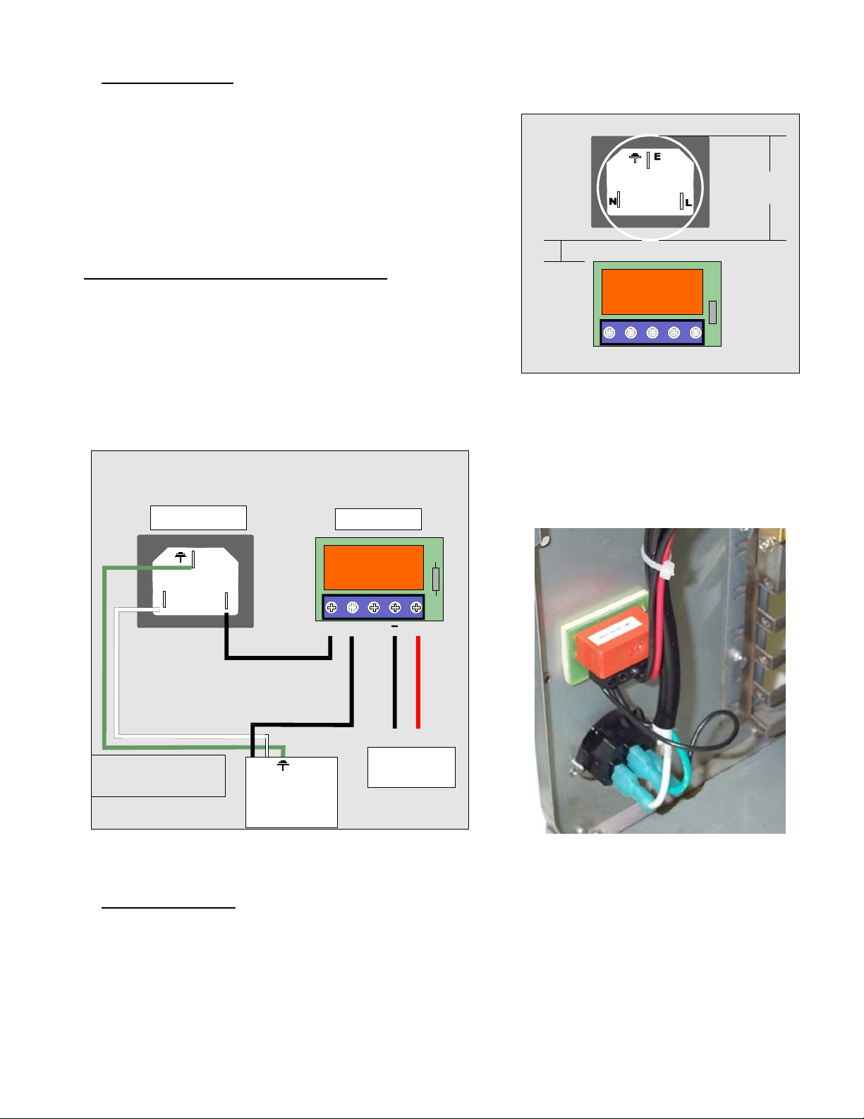
Proceed with electrical connections as described in fig.3
Black L wire from A/C socket to N\O (normally opened)
position on switch
Black L wire from S320-12 power supply to N\O position on
switch
White N wire from S320-12 power supply to N position on A/C
socket
Green Ground wire from S320-12 power supply to Ground on
A/C socket
The 4 pins Molex connector will then connect to the
computer power supply.
Relay switch connection diagram
A/C Socket
Relay switch
A/C Socket
Spacing
0.25"
N\O
Pump’s relay switch circuit board
N\O
_
Figure 4
+
The relay switch and A/C socket adapter installed
Hole
1.25"
E
N
WARNING! Al ways di sconnect
from A/C power source while
working with electrical devices.
L
N\O
N\O
N
L
+
Ground +12v
Computer
Power Supply
S320-12
Power s upply
Figure 5
3. Power Supply ventilation
The following information is optional, and subject to existing ventilation in your particular chassis. Please disregard if your computer chassis already
features a blowhole, with or without fan.
The S320-12 power supply features a built-in temperature controlled fan, which activates as needed. Since the power supply is being installed in a
confined area, and in order to reduce a heat build-up inside the chassis, it is essential to optimize exhaust of the hot air generated by the power
supply. A blowhole will accomplish just this, and should be located as close to, or preferably directly above the power supply exhaust vent. Ideally,
a low CFM 80mm fan should be added, if space permits. Such solution will greatly the activity of the power supply built-in cooling fan, resulting in
quieter operations, and lower temperatures both inside the computer and in the power supply. If such fan is installed, it should be extracting air from
the case (blowing towards the outside).
Figure 6
Rouchon Industries, Inc., dbA Swiftech™ – 1703 E. 28th St, signal Hill, CA 90755, USA – T (562) 595-8009 – F (562) 595-8769 – All content
Copyright Swiftech 2004 – Last edited 12-9-04 – Subject to revision without notice - 17 of 37 -
Page 18

The template below provides holes dimensions for installation of such 80mm fan blowhole. A fan guard and snap rivets are provided with the kit to
complete the installation.
DOUBLE-CHECK DIMENSIONS
PRIOR TO USING AS TEMPLATE
Rouchon Industries, Inc., dbA Swiftech™ – 1703 E. 28th St, signal Hill, CA 90755, USA – T (562) 595-8009 – F (562) 595-8769 – All content
Copyright Swiftech 2004 – Last edited 12-9-04 – Subject to revision without notice - 18 of 37 -
Page 19

MCW5002-775T assy. with TEC and gaskets 1 Céramique thermal compound 1
3/8” NPT to ½” barb fittings 2 Euro-style connector 1
Motherboard installation hardware pack 1
This product is intended for expert users only. Please consult with a qualified technician for installation. Improper installation may result in damage
to your components. Swiftech assumes no liability whatsoever, expressed or implied, for the use of these products, nor their installation.
The following instructions are subject to change without notice. Please visit our web site at www.swiftnets.com
Part Qty Part Qty
for updates.
Assembly exploded view
Figure 1
Rouchon Industries, Inc., dbA Swiftech™ – 1703 E. 28th St, signal Hill, CA 90755, USA – T (562) 595-8009 – F (562) 595-8769 – All content
Copyright Swiftech 2004 – Last edited 12-9-04 – Subject to revision without notice - 19 of 37 -
Page 20
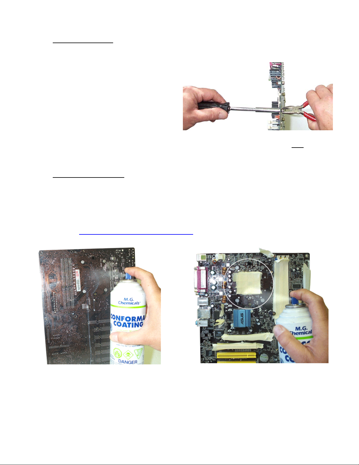
1. Preparing the motherboard
Remove the stock heatsink retention mechanism to reveal the fourmotherboard mounting holes.
Install a standoff in each one of the holes. As the diameter of the
mounting holes is usually larger than the diameter of the standoff
stem, be careful to keep the standoff approximately centered in the
MB holes. Secure the standoffs with the provided hex locknuts, and a
fiber washer on the backside of the MB as shown on fig. 1, using the
tools described fig. 2
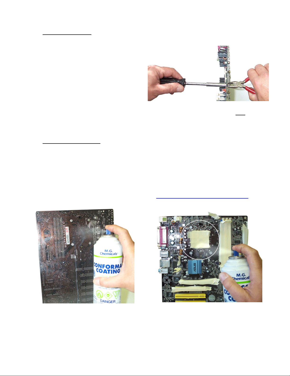
Figure 2
Use a ¼” socket tool to drive the standoff, and a small
to prevent the locknut from spinning. Torque value should not to
exceed 16 in. lbs. In other words JUST FIRM AND TIGHT, BUT
WITHOUT EXCESSIVE TORQUE.
pair of pliers
2. Condensation control measures
The following instructions are crucial to long lasting & reliable operations. Do not skip these steps, and do not take shortcuts. Permanent damage to
your components is likely to occur otherwise.
a. Motherboard preparation
• Conformal coating application: This step will positively ensure that any micro condensation occurring on small surface
mount components will not corrode or short-circuit the motherboard.
Procure a spray can of silicone conformal coating. We use M.G. chemicals Acrylic Conformal Coating, part # 419B-340g.
The product can be purchased at our online store here http://www.swiftnets.com/store/category.asp?CatID=11
products can also be used, but sprays are recommended for their ease of use.
- Equivalent
Figure 3 - Back of the motherboard:
Spray the back of the motherboard, concentrating on the area
immediately behind the CPU. Also spray all the way down, in a
vertical path directly under the CPU area. Allow time to dry, per
manufacturer specs.
Rouchon Industries, Inc., dbA Swiftech™ – 1703 E. 28th St, signal Hill, CA 90755, USA – T (562) 595-8009 – F (562) 595-8769 – All content Copyright
Swiftech 2004 – Last edited 12-9-04 – Subject to revision without notice - 20 of 37 -
Use masking tape to protect the CPU socket, and any connector sockets
in the immediate vicinity of the processor. A double layer of tape is
recommended for all sockets, as the spray may soak a single layer of
tape and contaminate the contacts.
Spray the area immediately surrounding the socket. It is not
recommended to spray further than the area circled in the above picture.
Allow the coating to be “dry to the touch” (20 minutes approximately),
Figure 4 - Front of the motherboard
Page 21
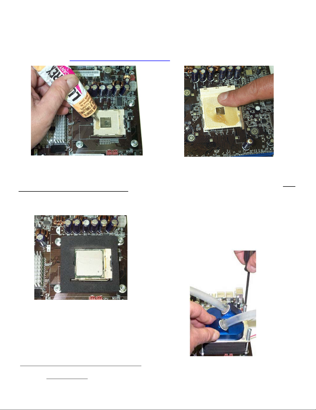
b. CPU preparation & water-block installation
Dielectric grease application: The following steps will ensure that condensation does not form inside of the CPU socket.
Procure a tube of dielectric grease. We use Luberex grease, available on our web site here:
http://www.swiftnets.com/store/category.asp?CatID=11
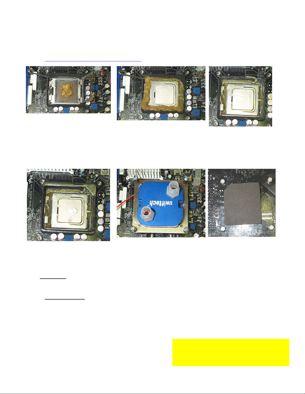
Step 1
1/ Install the motherboard gasket #1 (1/4” thick)
2/ Squirt a generous amount of dielectric grease
inside the socket center section.
and remove the masking tape. Then let the board dry completely per
manufacturer specs.
Step 2
3/ Place your CPU in the socket, and gently
push it down to pack the grease inside the
socket center section.
4/ squeeze more dielectric grease all around,
between the gasket and the CPU socket
Step 3
5/ Close the socket lever
6/ Clean off all the excess grease,
particularly on the CPU itself. The
surface of the CPU needs to be
clean for the next application of
thermal grease.
Step 4
7/ Squeeze a small amount of Céramique
thermal compound on the CPU.
8/ Peel-off the protective paper from
motherboard gasket #2 (1/8” thick) and carefully
align the gasket over motherboard gasket #1,
with the sticky side up
9/ Align the water-block mounting posts with the
motherboard standoffs, and tighten the screws
in a cross pattern. Do not over-tighten the
screws or they could jam into the standoffs,
making further removal difficult.
The water-block is now installed
3. Electrical Installation
IMPORTANT WARNING: Solder joints of the wires to the thermoelectric module are extremely fragile. Bending the wires at their root will break the
solder joint, with no possible repair. Swiftech will not honor the warranty for broken wires.
a. Recommended installation: Connecting to a dedicated auxiliary power supply
Minimum requirements for a dedicated power supply are 25A @ +12V.
Your TEC module has been measured to draw 18 amps at 12 volts. For this
reason, we recommend using the “Meanwell S320-12” auxiliary power supply,
available on our website in the Thermoelectric accessories section.
Rouchon Industries, Inc., dbA Swiftech™ – 1703 E. 28th St, signal Hill, CA 90755, USA – T (562) 595-8009 – F (562) 595-8769 – All content Copyright
Swiftech 2004 – Last edited 12-9-04 – Subject to revision without notice - 21 of 37 -
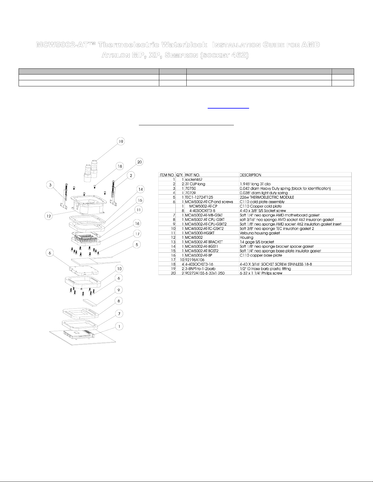
Step 5
10/ There will be grease squeezing
off from the holes behind the
motherboard. Wipe it out clean.
11/ Stick the neoprene gasket
directly behind the CPU (use the
center section of motherboard
gasket #1). This will prevent
condensation to form here over time.
CCRRIITTIICCAALL RREECCOOMMMMEENNDDAATTIIOONNSS MMUUSSTT RREEAADD!!!!!!
Never run a thermoelectric module without coolant flowing
in the circuit. This will result in catastrophic failure of the
cooling element, and may cause any/all of the following:
Tubing to burst open due to coolant overheating
Step 6
Page 22
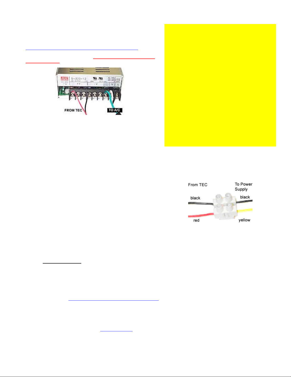
The TEC module is provided with “bare wires” to facilitate installation with screw
type terminals such as featured in the S320-12 power supply
Connect red wire from TEC module to the +V terminal, and black wire to the –V
terminal as shown in figure 5.
A complete installation guide for the S320-12 power supply kit is available here:
http://www.swiftnets.com/products/installationguide_S320-12kit.pdf
includes a wiring harness and a relay switch to synchronize the power to the
S320-12 with your computer, which is a highly recommended (read critical
recommendations)
Figure 5
b. Connecting to your computer power supply:
Important Warning: to connect the MCW5002-PTcooler to an ATX
computer power supply, you must carefully consider the existing
requirements of other devices connected on the +12V line. Connecting to
an underpowered unit will definitely damage the power supply.
Minimum requirements for an ATX computer power supply: 36A at +12V in
a typical computer setup.
When you connect the MCW5002-PT to an ATX power supply, you need
to cut the wiring to one of the power supply Molex connectors, and use a
different connector between power supply, and thermoelectric. This is
because Molex connectors are not rated for 18Amps current, and may
overheat.
- This kit
Permanent failure of the Peltier module
Permanent damage to the CPU and/or motherboard
It is highly recommended to dedicate the auxiliary power
supply for the thermoelectric module to the computer
power-supply, so that the Peltier module will never run by
itself without cooling fluid.
For this purpose, we recommend using the following
accessory, available in our online shopping cart: PRS Kit II.
Includes: Relay Switch Circuit board AC socket, S/S socket
cover, power cord. This relay switch is rated for 110 to
220~240 volts and up to 50A inrush current. It is suitable for
use with the S-320-12 Meanwell power supply recommended
above.
If you run your computer unattended for extended periods
of time, it is also a good practice to setup an alarm
temperature, which will shut down the computer in case the
CPU overheats. Such alarm/shut down process should be
tested as functional.
WARNING! Wires from the thermoelectric module do get hot
(this is normal). Make sure that the wires do not touch devices
that are heat sensitive, such as vinyl tubes for example. Heat
from the wires may cause the vinyl to deform, and/or burst.
c. Connecting TEC wires to the power supply:
Use the provided euro-style wire connector as shown in fig 6
below, or a similar device with a current rating of at least 25
amps. Connect red wire from TEC module to +12V of P/S
(Yellow wire), and black wire to black wire:
due to excess heat
Figure 6
If you need wiring extensions: use 16 gage stranded wire.
Connect the extension to the existing wires with terminal
splices, or solder the butts, and insulate with shrink tubing.
4. Hydraulic Installation
The MCW5002-775T is shipped with ½” barb to 3/8” NPT nylon fittings. These fittings should be installed using Teflon tape or
plumbers “goop”. If fittings need to be replaced for a difference tubing size, do not use brass fittings, because of the galvanic
corrosion that will take place between copper or brass and the MCW5002-PT aluminum housing. Always use nylon fittings.
Inlet and outlet are interchangeable.
Type of Coolant:
For best performance, use 95% distilled water, and 5% Swiftech brand “HydrX” corrosion inhibitor (available here:
In all cases, you must use Distilled water and a corrosion inhibitor with the MCW5002 water-block. Regular automotive
NEVER use tap water, even for a short-term test.
Not following the above instructions constitutes misuse (*) of the product, and will void your warranty.
Final inspection: Once the installation is completed, it is always a good idea to test the circuit for leaks, prior to powering up the computer.
Troubleshooting help is available on our web site at www.swiftnets.com
Rouchon Industries, Inc., dbA Swiftech™ – 1703 E. 28th St, signal Hill, CA 90755, USA – T (562) 595-8009 – F (562) 595-8769 – All content Copyright
Swiftech 2004 – Last edited 12-9-04 – Subject to revision without notice - 22 of 37 -
http://www.swiftnets.com/store/category.asp?CatID=2
anti-freeze is acceptable. Automotive manufacturers recommend that not less than 25% is used.
, or by calling customer support at 562-595-8009.
, under the “accessories” section).
Page 23

MCW5002-PT assy with TEC and gaskets 1 Arctic Alumina thermal compound 1
3/8” NPT to ½” barb fittings 2 Euro-style connector 1
Motherboard installation hardware pack 1
This product is intended for expert users only. Please consult with a qualified technician for installation. Improper installation may result in damage to
your components. Swiftech assumes no liability whatsoever, expressed or implied, for the use of these products, nor their installation. The
following instructions are subject to change without notice. Please visit our web site at www.swiftnets.com
Part Qty Part Qty
for updates.
Assembly exploded view & part numbers
Figure 1
Rouchon Industries, Inc., dbA Swiftech™ – 1703 E. 28th St, signal Hill, CA 90755, USA – T (562) 595-8009 – F (562) 595-8769 – All content Copyright
Swiftech 2004 – Last edited 12-9-04 – Subject to revision without notice - 23 of 37 -
Page 24
1. Preparing the motherboard
Remove the stock heatsink retention frame (the black plastic frame
that clips down to your motherboard). This will reveal the four
mounting holes used to install the MCW5000-PT retention
standoffs.
Install a standoff in each one of the holes. As the diameter of the
mounting holes is much larger than the diameter of the standoff stem,
be careful to keep the standoff approximately centered in the MB
holes. Secure standoffs with hex locknuts, and a fiber washer on
backside of the MB as shown on fig. 1, using the tools described fig. 2
Figure 2
Use a ¼” socket tool to drive the standoff, and a small
to prevent the locknut from spinning. Torque value should not to
exceed 16 in. lbs. In other words JUST TIGHT, WITHOUT EXCESSIVE
TORQUE.
pair of pliers
2. Condensation control measures
The following instructions are crucial to long lasting & reliable operations. Do not skip these steps, and do not take shortcuts. Permanent damage to
your components is likely to occur otherwise.
a. Motherboard preparation
• Conformal coating application: This step will positively ensure that any micro condensation occurring on small surface
mount components will not corrode or short-circuit the motherboard. Procure a spray can of silicone conformal coating. We
use M.G. chemicals Acrylic Conformal Coating, part # 419B-340g. The product can be purchased at our online store here
http://www.swiftnets.com/store/category.asp?CatID=11
recommended for their ease of use.
- Equivalent products can also be used, but sprays are
Figure 3
Spray the back of the motherboard, concentrating on the area immediately
behind the CPU. Also spray all the way down, in a vertical path directly
under the CPU area. Allow time to dry, per manufacturer specs.
Rouchon Industries, Inc., dbA Swiftech™ – 1703 E. 28th St, signal Hill, CA 90755, USA – T (562) 595-8009 – F (562) 595-8769 – All content Copyright
Swiftech 2004 – Last edited 12-9-04 – Subject to revision without notice - 24 of 37 -
Use masking tape to protect the CPU socket, and any connector sockets
in the immediate vicinity of the processor. A double layer of tape is
recommended for all sockets, as the spray may soak a single layer of tape
and contaminate the contacts.
Spray the area immediately surrounding the socket. It is not recommended
to spray further than the area circled in the above picture. Allow the
coating to be “dry to the touch” (20 minutes approximately), and remove
the masking tape. Then let the board dry completely per manufacturer
specs.
Figure 4
Page 25
Squirt a generous amount of grease onto the socket. Force the grease inside of the pin-holes with your finger. Make sure that
To complete the condensation prevention measures, simply apply the neoprene sticker provided with your MCW5002-PT accessories to the
back of the motherboard, directly behind the processor.
b. CPU and cooler installation:
• Dielectric grease application: This step will ensure that condensation does not form inside of the CPU socket.
Procure a tube of dielectric grease. We use Luberex grease, available on our web site here:
http://www.swiftnets.com/store/category.asp?CatID=11
Figure 5
Securing the MCW5002-PT cooler to the motherboard:
Install the MCW5002-PT assembly onto your processor, as shown in figure 8.
Gradually tighten the screws in a cross pattern until you feel that they reach
the central area of the socket is completely filled with grease.
the bottom of the standoff. A “finger-tight” lock is sufficient.
Figure 6
Remove the peel-off paper back from the
motherboard gasket, and install it as shown above.
The sticky side should be towards the motherboard.
Insert the processor into the socket. Since you
have grease inside the socket, some hydraulic
pressure lift may occur: for this reason, make sure
that the processor sits perfectly flat, and is inserted
all the way into the socket.
Then, drop a small amount of high quality thermal
compound onto the center of the processor core.
Installation of the cooler to the motherboard is now complete!
3. Electrical Installation
Rouchon Industries, Inc., dbA Swiftech™ – 1703 E. 28th St, signal Hill, CA 90755, USA – T (562) 595-8009 – F (562) 595-8769 – All content Copyright
Swiftech 2004 – Last edited 12-9-04 – Subject to revision without notice - 25 of 37 -
Figure 7
Figure 8 - (showing an MCW5000-PT)
Page 26

IMPORTANT WARNING: Solder joints of the wires to the thermoelectric module are extremely fragile. Bending the wires at their root will break the
solder joint, with no possible repair. Swiftech will not honor the warranty for broken wires.
a. Recommended installation: Connecting to a dedicated auxiliary power supply
Minimum requirements for a dedicated power supply are 25A @ +12V.
Your TEC module has been measured to draw 18 amps at 12 volts. For this
reason, we recommend using the “Meanwell S320-12” auxiliary power supply,
available on our website in the Thermoelectric accessories section.
The TEC module is provided with “bare wires” to facilitate installation with screw
type terminals such as featured in the S320-12 power supply
Connect red wire from TEC module to the +V terminal, and black wire to the –V
terminal as shown in figure 10.
A complete installation guide for the S320-12 power supply kit is available here:
http://www.swiftnets.com/products/installationguide_S320-12kit.pdf
includes a wiring harness and a relay switch to synchronize the power to the
S320-12 with your computer, which is a highly recommended (read critical
recommendations)
Figure 10
b. Connecting to your computer power supply:
Important Warning: to connect the MCW5002-PTcooler to an ATX
computer power supply, you must carefully consider the existing
requirements of other devices connected on the +12V line. Connecting to
an underpowered unit will definitely damage the power supply.
Minimum requirements for an ATX computer power supply: 36A at +12V in
a typical computer setup.
When you connect the MCW5002-PT to an ATX power supply, you need
to cut the wiring to one of the power supply Molex connectors, and use a
different connector between power supply, and thermoelectric. This is
because Molex connectors are not rated for 18Amps current, and may
overheat.
- This kit
CCRRIITTIICCAALL RREECCOOMMMMEENNDDAATTIIOONNSS MMUUSSTT RREEAADD!!!!!!
Never run a thermoelectric module without coolant flowing
in the circuit. This will result in catastrophic failure of the
cooling element, and may cause any/all of the following:
Tubing to burst open due to coolant overheating
Permanent failure of the Peltier module
Permanent damage to the CPU and/or motherboard
due to excess heat
It is highly recommended to dedicate the auxiliary power
supply for the thermoelectric module to the computer
power-supply, so that the Peltier module will never run by
itself without cooling fluid.
For this purpose, we recommend using the following
accessory, available in our online shopping cart: PRS Kit II.
Includes: Relay Switch Circuit board AC socket, S/S socket
cover, power cord. This relay switch is rated for 110 to
220~240 volts and up to 50A inrush current. It is suitable for
use with the S-320-12 Meanwell power supply recommended
above.
If you run your computer unattended for extended periods
of time, it is also a good practice to setup an alarm
temperature, which will shut down the computer in case the
CPU overheats. Such alarm/shut down process should be
tested as functional.
WARNING! Wires from the thermoelectric module do get hot
(this is normal). Make sure that the wires do not touch devices
that are heat sensitive, such as vinyl tubes for example. Heat
from the wires may cause the vinyl to deform, and/or burst.
c. Connecting TEC wires to the power supply:
Use the provided euro-style wire connector as shown in fig
11 below, or a similar device with a current rating of at least 25
amps. Connect red wire from TEC module to +12V of P/S
(Yellow wire), and black wire to black wire:
Figure 11
If you need wiring extensions: use 16 gage stranded wire.
Connect the extension to the existing wires with terminal
splices, or solder the butts, and insulate with shrink tubing.
4. Hydraulic Installation
The MCW5002-PT is shipped with ½” barb to 3/8” NPT nylon fittings. These fittings should be installed using Teflon tape or
plumbers “goop”. If fittings need to be replaced for a difference tubing size, do not use brass fittings, because of the galvanic
corrosion that will take place between copper or brass and the MCW5002-PT aluminum housing. Always use nylon fittings.
Inlet and outlet are interchangeable.
Rouchon Industries, Inc., dbA Swiftech™ – 1703 E. 28th St, signal Hill, CA 90755, USA – T (562) 595-8009 – F (562) 595-8769 – All content Copyright
Swiftech 2004 – Last edited 12-9-04 – Subject to revision without notice - 26 of 37 -
Page 27

Type of Coolant:
Final inspection
Once the installation is completed, it is always a good idea to test the circuit for leaks, prior to powering up the computer. Troubleshooting
help is available on our web site at www.swiftnets.com
For best performance, use 95% distilled water, and 5% Swiftech brand “HydrX” corrosion inhibitor (available here:
http://www.swiftnets.com/store/category.asp?CatID=2
In all cases, you must use Distilled water and a corrosion inhibitor with the MCW5002 water-block. Regular automotive
anti-freeze is acceptable. Automotive manufacturers recommend that not less than 25% is used.
NEVER use tap water, even for a short-term test.
Not following the above instructions constitutes misuse (*) of the product, and will void your warranty.
, or by calling customer support at 562-595-8009.
, under the “accessories” section).
Rouchon Industries, Inc., dbA Swiftech™ – 1703 E. 28th St, signal Hill, CA 90755, USA – T (562) 595-8009 – F (562) 595-8769 – All content Copyright
Swiftech 2004 – Last edited 12-9-04 – Subject to revision without notice - 27 of 37 -
Page 28
MCW5002-AT assy with TEC and gaskets 1 Arctic Alumina thermal compound 1
3/8” NPT to ½” barb fittings 2 Euro-style connector 1
This product is intended for expert users only. Please consult with a qualified technician for installation. Improper installation may result in damage to
your components. Swiftech assumes no liability whatsoever, expressed or implied, for the use of these products, nor their installation. The
following instructions are subject to change without notice. Please visit our web site at www.swiftnets.com
Part Qty Part Qty
for updates.
Assembly exploded view & part numbers
Figure 1
Rouchon Industries, Inc., dbA Swiftech™ – 1703 E. 28th St, signal Hill, CA 90755, USA – T (562) 595-8009 – F (562) 595-8769 – All content Copyright
Swiftech 2004 – Last edited 12-9-04 – Subject to revision without notice - 28 of 37 -
Page 29

1. Condensation control measures
The following instructions are crucial to long lasting & reliable operations. Do not skip these steps, and do not take shortcuts. Permanent damage to
your components is likely to occur otherwise.
a. Motherboard preparation
• Conformal coating application: This step will positively ensure that any micro condensation occurring on small surface
mount components will not corrode or short-circuit the motherboard. Procure a spray can of silicone conformal coating. We
use M.G. chemicals Acrylic Conformal Coating, part # 419B-340g. The product can be purchased at our online store here
http://www.swiftnets.com/store/category.asp?CatID=11
recommended for their ease of use.
- Equivalent products can also be used, but sprays are
Figure 2
Spray the back of the motherboard, concentrating on the area immediately
behind the CPU. Also spray all the way down, in a vertical path directly
under the CPU area. Allow time to dry, per manufacturer specs.
• Dielectric grease application: This step will ensure that condensation does not form inside of the CPU socket.
Procure a tube of dielectric grease. We use Luberex grease, available on our web site here:
http://www.swiftnets.com/store/category.asp?CatID=11
Figure 3
Use masking tape to protect the CPU socket, and any connector sockets
in the immediate vicinity of the processor. A double layer of tape is
recommended for all sockets, as the spray may soak a single layer of tape
and contaminate the contacts.
Spray the area immediately surrounding the socket. It is not recommended
to spray further than the area circled in the above picture. Allow the
coating to be “dry to the touch” (20 minutes approximately), and remove
the masking tape. Then let the board dry completely per manufacturer
specs.
Rouchon Industries, Inc., dbA Swiftech™ – 1703 E. 28th St, signal Hill, CA 90755, USA – T (562) 595-8009 – F (562) 595-8769 – All content Copyright
Swiftech 2004 – Last edited 12-9-04 – Subject to revision without notice - 29 of 37 -
Page 30

Figure 4
Squirt a generous amount of grease onto the socket. Force the grease inside of the pin-holes with your finger. Make sure that
b. CPU and cooler installation:
Figure 6
Remove the peel-off paper back from the
motherboard gasket, and install it as shown above.
The sticky side should be towards the motherboard.
Insert the processor into the socket. Since you
have grease inside the socket, some hydraulic
pressure lift may occur: for this reason, make sure
that the processor sits perfectly flat, and is inserted
all the way into the socket.
Then, drop a small amount of high quality thermal
compound into the center of the processor core.
Securing the MCW5002-AT cooler to the motherboard:
Initial check: make sure that the retention clips are at their lowest position by
tightening the 2 spring loaded Philips screws until the springs are fully
compressed (do not over-tighten)
Engage one side of the clip under the CPU socket retention lugs
Gently pull the water-block in the opposite direction and push it down to
catch the opposite set of socket lugs. The clip will snap underneath the
socket lugs.
Firmly press the base of the clips (through the gaskets) between middle
finger and thumb as shown in Figure 7 to compress them against the socket
(this will prevent the clips for disengaging themselves from underneath the
tabs at start-up) then gradually and alternatively loosen the two spring
loaded Philips screws to secure the water-block.
Continue backing off the screws until the head of each screw completely
clears the top of the bracket, as shown figure 8.
the central area of the socket is completely filled with grease.
Figure 5
Figure 7
Rouchon Industries, Inc., dbA Swiftech™ – 1703 E. 28th St, signal Hill, CA 90755, USA – T (562) 595-8009 – F (562) 595-8769 – All content Copyright
Swiftech 2004 – Last edited 12-9-04 – Subject to revision without notice - 30 of 37 -
Page 31

Figure 8
Installation of the cooler to the motherboard is now complete!
2. Electrical Installation
IMPORTANT WARNING: Solder joints of the wires to the thermoelectric module are extremely fragile. Bending the wires at their root will break the
solder joint, with no possible repair. Swiftech will not honor the warranty for broken wires.
a. Recommended installation: Connecting to a dedicated auxiliary
power supply
Minimum requirements for a dedicated power supply are 25A @
+12V.
Your TEC module has been measured to draw 18 amps at 12 volts.
For this reason, we recommend using the “Meanwell S320-12”
auxiliary power supply, available on our website in the Thermoelectric
accessories section.
The TEC module is provided with “bare wires” to facilitate installation
with screw type terminals such as featured in the S320-12 power
supply
Connect red wire from TEC module to the +V terminal, and black wire
to the –V terminal as shown in figure 9.
A complete installation guide for the S320-12 power supply kit is
available here:
http://www.swiftnets.com/products/installationguide_S320-12kit.pdf
This kit includes a wiring harness and a relay switch to synchronize
the power to the S320-12 with your computer, which is a highly
recommended (read below)
Never run a thermoelectric module without coolant flowing in the
circuit. This will result in catastrophic failure of the cooling element, and
may cause any/all of the following:
It is highly recommended to dedicate the auxiliary power supply for
the thermoelectric module to the computer power-supply, so that the
Peltier module will never run by itself without cooling fluid.
For this purpose, we recommend using the following accessory, available
-
in our online shopping cart: PRS Kit II. Includes: Relay Switch Circuit
board AC socket, S/S socket cover, power cord. This relay switch is rated
for 110 to 220~240 volts and up to 50A inrush current. It is suitable for use
with the S-320-12 Meanwell power supply recommended above.
If you run your computer unattended for extended periods of time, it
is also a good practice to setup an alarm temperature, which will shut
down the computer in case the CPU overheats. Such alarm/shut down
process should be tested as functional.
WARNING! Wires from the thermoelectric module do get hot (this is
normal). Make sure that the wires do not touch devices that are heat
sensitive, such as vinyl tubes for example. Heat from the wires may cause
the vinyl to deform, and/or burst.
CCRRIITTIICCAALL RREECCOOMMMMEENNDDAATTIIOONNSS MMUUSSTT RREEAADD!!!!!!
Tubing to burst open due to coolant overheating
Permanent failure of the Peltier module
Permanent damage to the CPU and/or motherboard due to
excess heat
Figure 10
Rouchon Industries, Inc., dbA Swiftech™ – 1703 E. 28th St, signal Hill, CA 90755, USA – T (562) 595-8009 – F (562) 595-8769 – All content Copyright
Swiftech 2004 – Last edited 12-9-04 – Subject to revision without notice - 31 of 37 -
Page 32

b. Connecting to your computer power supply:
Important Warning: to connect the MCW5002-ATcooler to an
ATX computer power supply, you must carefully consider the
existing requirements of other devices connected on the +12V line.
Connecting to an underpowered unit will definitely damage the
power supply.
Minimum requirements for an ATX computer power supply: 36A at
+12V in a typical computer setup.
When you connect the MCW5002-AT to an ATX power supply,
you need to cut the wiring to one of the power supply Molex
connectors, and use a different connector between power supply,
and thermoelectric. This is because Molex connectors are not rated
for 18Amps current, and may overheat.
3. Hydraulic Installation
Use the provided euro-style wire connector as shown in fig 11 below,
or a similar device with a current rating of at least 25 amps. Connect
red wire from TEC module to +12V of P/S (Yellow wire), and black wire
to black wire:
If you need wiring extensions: use 16 gage stranded wire. Connect
the extension to the existing wires with terminal splices, or solder the
butts, and insulate with shrink tubing.
c. Connecting TEC wires to the power supply:
Figure 11
Final inspection: Once the installation is completed, it is always a good idea to test the circuit for leaks, prior to powering up the computer.
Troubleshooting help is available on our web site at www.swiftnets.com
The MCW5002-AT is shipped with ½” barb to 3/8” NPT nylon fittings. These fittings should be installed using Teflon tape or
plumbers “goop”. If fittings need to be replaced for a difference tubing size, do not use brass fittings, because of the galvanic
corrosion that will take place between copper or brass and the MCW5002-AT aluminum housing. Always use nylon fittings.
Inlet and outlet are interchangeable.
Type of Coolant:
For best performance, use 95% distilled water, and 5% Swiftech brand “HydrX” corrosion inhibitor (available here:
http://www.swiftnets.com/store/category.asp?CatID=2
In all cases, you must use Distilled water and a corrosion inhibitor with the MCW5002 water-block. Regular automotive
anti-freeze is acceptable. Automotive manufacturers recommend that not less than 25% is used.
NEVER use tap water, even for a short-term test.
Not following the above instructions constitutes misuse (*) of the product, and will void your warranty.
, or by calling customer support at 562-595-8009.
, under the “accessories” section).
Rouchon Industries, Inc., dbA Swiftech™ – 1703 E. 28th St, signal Hill, CA 90755, USA – T (562) 595-8009 – F (562) 595-8769 – All content Copyright
Swiftech 2004 – Last edited 12-9-04 – Subject to revision without notice - 32 of 37 -
Page 33
MCW5002-64T assy with TEC and gaskets 1 Arctic Alumina thermal compound 1
3/8” NPT to ½” barb fittings 2 Euro-style connector 1
This product is intended for expert users only. Please consult with a qualified technician for installation. Improper installation may result in damage to
your components. Swiftech assumes no liability whatsoever, expressed or implied, for the use of these products, nor their installation. The
following instructions are subject to change without notice. Please visit our web site at www.swiftnets.com
Part Qty Part Qty
for updates.
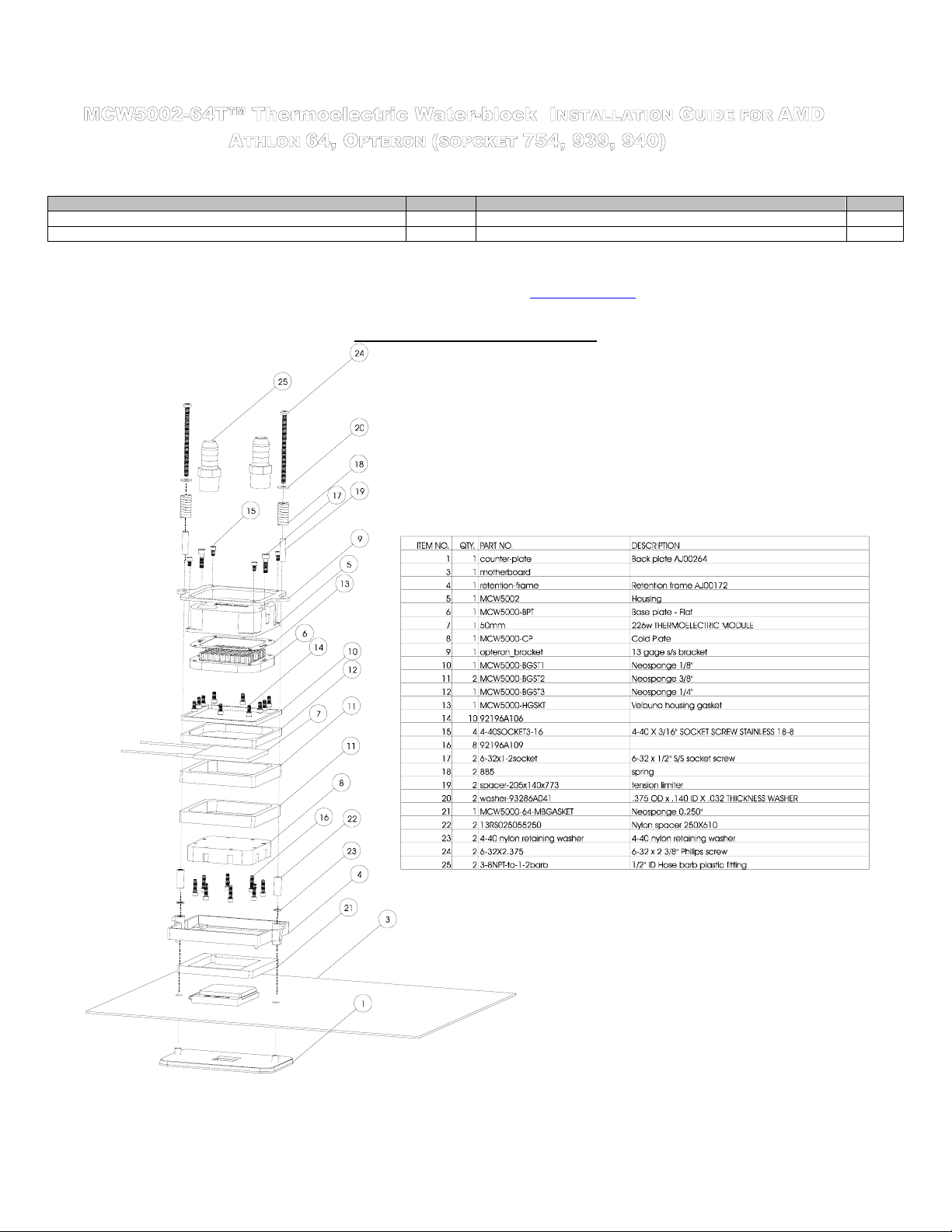
Assembly exploded view & part numbers
Figure 1
Rouchon Industries, Inc., dbA Swiftech™ – 1703 E. 28th St, signal Hill, CA 90755, USA – T (562) 595-8009 – F (562) 595-8769 – All content Copyright
Swiftech 2004 – Last edited 12-9-04 – Subject to revision without notice - 33 of 37 -
Page 34
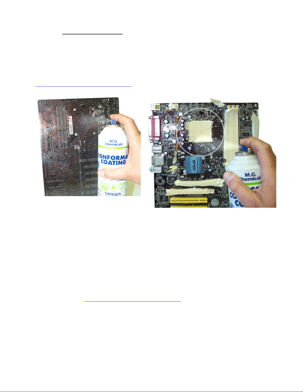
1. Condensation control measures
The following instructions are crucial to long lasting & reliable operations. Do not skip these steps, and do not take shortcuts. Permanent
damage to your components is likely to occur otherwise.
a. Motherboard preparation
Conformal coating application: This step will positively ensure that any micro condensation occurring on small surface mount
components will not corrode or short-circuit the motherboard. Procure a spray can of silicone conformal coating. We use M.G. chemicals
Acrylic Conformal Coating, part # 419B-340g. The product can be purchased at our online store here
http://www.swiftnets.com/store/category.asp?CatID=11
ease of use.
- Equivalent products can also be used, but sprays are recommended for their
Figure 2
Spray the back of the motherboard, concentrating on the
area immediately behind the CPU. Also spray all the way
down, in a vertical path directly under the CPU area. Allow
time to dry, per manufacturer specs.
• Dielectric grease application: This step will ensure that condensation does not form inside of the CPU
socket.
Procure a tube of dielectric grease. We use Luberex grease, available on our web site here:
http://www.swiftnets.com/store/category.asp?CatID=11
Figure 3
Use masking tape to protect the CPU socket, and any connector sockets
in the immediate vicinity of the processor. A double layer of tape is
recommended for all sockets, as the spray may soak a single layer of
tape and contaminate the contacts.
Spray the area immediately surrounding the socket. It is not
recommended to spray further than the area circled in the above picture.
Allow the coating to be “dry to the touch” (20 minutes approximately), and
remove the masking tape. Then let the board dry completely per
manufacturer specs.
Rouchon Industries, Inc., dbA Swiftech™ – 1703 E. 28th St, signal Hill, CA 90755, USA – T (562) 595-8009 – F (562) 595-8769 – All
content Copyright Swiftech 2004 – Last edited 12-9-04 – Subject to revision without notice - 34 of 37 -
Page 35
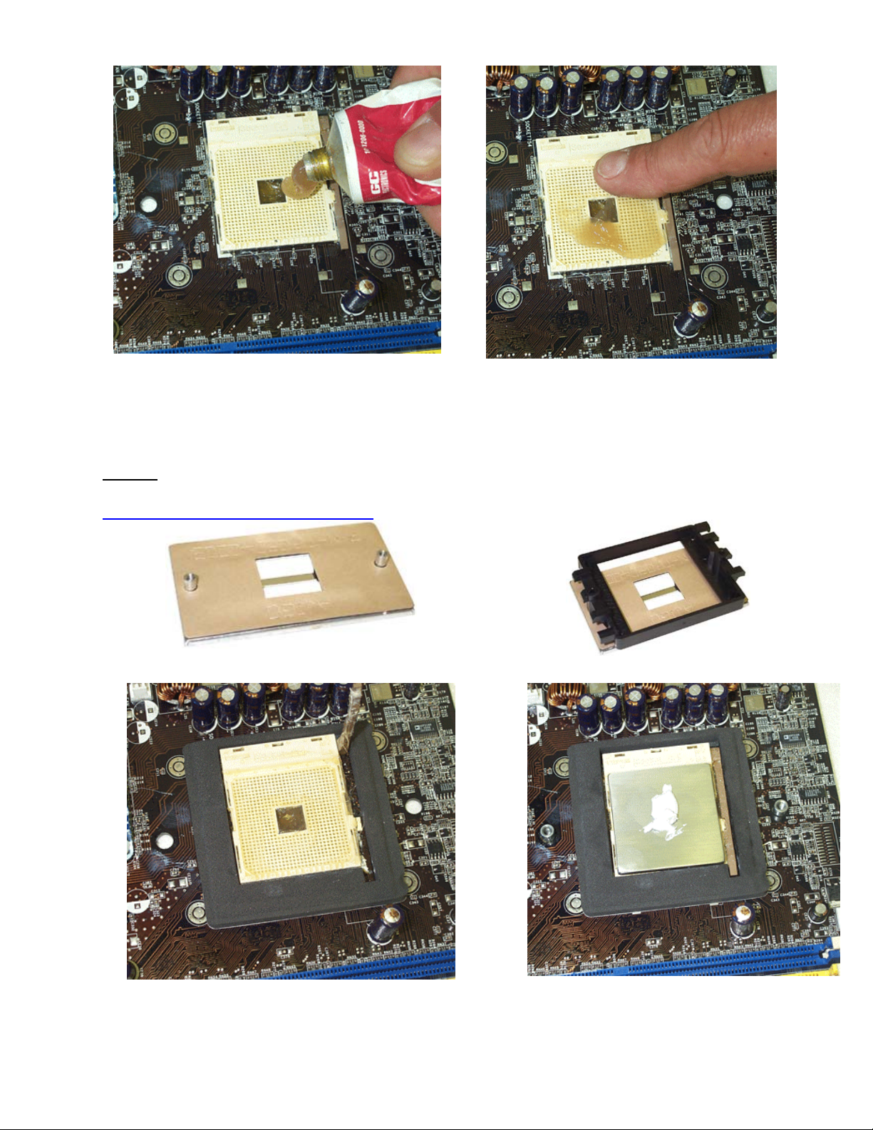
Figure 4
Squirt a generous amount of grease onto the socket. Force the grease inside of the pin holes with your finger. Make
Preamble:
Some motherboard manufacturers use plastic back plates and snap-rivets to attach the CPU holding frame to the back-plate, which
cannot be used with the MCW5002-64T. AMD recommended backing plates and retention frames are available online on our site at:
http://www.swiftnets.com/store/category.asp?CatID=1
c. CPU and cooler installation:
The MCW5002-64T requires the AMD recommended motherboard backing plates (made out of metal) for its installation.
Part # AJ00264 backing plate alone
sure that the central area of the socket is completely filled with
Part # AJ00172 complete retention frame & backing plate
Figure 5
grease.
Figure 6
Remove the peel-off paper back from the motherboard gasket, and install Insert the processor into the socket.
Rouchon Industries, Inc., dbA Swiftech™ – 1703 E. 28th St, signal Hill, CA 90755, USA – T (562) 595-8009 – F (562) 595-8769 – All
content Copyright Swiftech 2004 – Last edited 12-9-04 – Subject to revision without notice - 35 of 37 -
Figure 7
Page 36

it as shown above. The sticky side should be towards the motherboard. Since you have grease inside the socket, some hydraulic pressure
Figure 8
Place the stock plastic retention over the gasket as shown above Secure the MCW5002-64T cooler to the motherboard by
Installation of the cooler to the motherboard is now complete. You can re-install the motherboard inside your chassis at this time.
lift may occur: for this reason, make sure that the processor sits
perfectly flat, and is inserted all the way into the socket. Then,
drop a small amount of high quality thermal compound into the
center of the processor core.
Figure 9
alternatively and gradually tightening the 2 retention screws.
2. Electrical Installation
IMPORTANT WARNING: Solder joints of the wires to the thermoelectric module are extremely fragile. Bending the wires at their root
will break the solder joint, with no possible repair. Swiftech will not honor the warranty for broken wires.
a. Recommended installation: Connecting to a dedicated auxiliary
power supply
Minimum requirements for a dedicated power supply are 25A @
+12V.
Your TEC module has been measured to draw 18 amps at 12
volts. For this reason, we recommend using the “Meanwell S32012” auxiliary power supply, available on our website in the
Thermoelectric accessories section.
The TEC module is provided with “bare wires” to facilitate
installation with screw type terminals such as featured in the S32012 power supply
Connect red wire from TEC module to the +V terminal, and black
wire to the –V terminal as shown in figure 10.
A complete installation guide for the S320-12 power supply kit is
available here:
http://www.swiftnets.com/products/installationguide_S320-12kit.pdf
- This kit includes a wiring harness and a relay switch to
synchronize the power to the S320-12 with your computer, which is
a highly recommended (read critical recommendations)
CCRRIITTIICCAALL RREECCOOMMMMEENNDDAATTIIOONNSS MMUUSSTT RREEAADD!!!!!!
Never run a thermoelectric module without coolant flowing in
the circuit. This will result in catastrophic failure of the cooling
element, and may cause any/all of the following:
Tubing to burst open due to coolant overheating
Permanent failure of the Peltier module
Permanent damage to the CPU and/or
It is highly recommended to dedicate the auxiliary power
supply for the thermoelectric module to the computer powersupply, so that the Peltier module will never run by itself
without cooling fluid.
For this purpose, we recommend using the following
accessory, available in our online shopping cart: PRS Kit II.
Includes: Relay Switch Circuit board AC socket, S/S socket
cover, power cord. This relay switch is rated for 110 to
220~240 volts and up to 50A inrush current. It is suitable for
use with the S-320-12 Meanwell power supply recommended
above.
Ifyou run your computer unattended for extended periods of
motherboard due to excess heat
Rouchon Industries, Inc., dbA Swiftech™ – 1703 E. 28th St, signal Hill, CA 90755, USA – T (562) 595-8009 – F (562) 595-8769 – All
content Copyright Swiftech 2004 – Last edited 12-9-04 – Subject to revision without notice - 36 of 37 -
Page 37
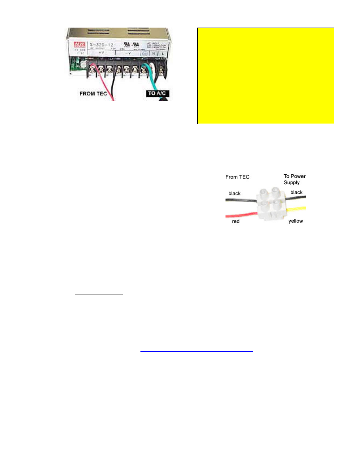
time, it is also a good practice to setup an alarm temperature,
which will shut down the computer in case the CPU
overheats. Such alarm/shut down process should be tested
as functional.
WARNING! Wires from the thermoelectric module do get
hot (this is normal). Make sure that the wires do not
touch devices that are heat sensitive, such as vinyl tubes
for example. Heat from the wires may cause the vinyl to
deform, and/or burst.
Figure 10
b. Connecting to your computer power supply:
Important Warning: to connect the MCW5002-64Tcooler
to an ATX computer power supply, you must carefully
consider the existing requirements of other devices
connected on the +12V line. Connecting to an underpowered
unit will definitely damage the power supply.
Minimum requirements for an ATX computer power supply:
36A at +12V in a typical computer setup.
When you connect the MCW5002-64T to an ATX power
supply, you need to cut the wiring to one of the power supply
Molex connectors, and use a different connector between
power supply, and thermoelectric. This is because Molex
connectors are not rated for 18Amps current, and may
overheat.
3. Hydraulic Installation
c. Connecting TEC wires to the power supply:
Use the provided euro-style wire connector
as shown in fig 11 below, or a similar device
with a current rating of at least 25 amps.
Connect red wire from TEC module to +12V of
P/S (Yellow wire), and black wire to black
wire:
If you need wiring extensions: use 16 gage stranded wire.
Connect the extension to the existing wires with terminal
splices, or solder the butts, and insulate with shrink tubing.
Figure 11
Final inspection: Once the installation is completed, it is always a good idea to test the circuit for leaks, prior to powering up
the computer. Troubleshooting help is available on our web site at www.swiftnets.com
8009.
Rouchon Industries, Inc., dbA Swiftech™ – 1703 E. 28th St, signal Hill, CA 90755, USA – T (562) 595-8009 – F (562) 595-8769 – All
content Copyright Swiftech 2004 – Last edited 12-9-04 – Subject to revision without notice - 37 of 37 -
The MCW5002-64T is shipped with ½” barb to 3/8” NPT nylon fittings. These fittings should be installed using Teflon
tape or plumbers “goop”. If fittings need to be replaced for a difference tubing size, do not use brass fittings, because
of the galvanic corrosion that will take place between copper or brass and the MCW5002-64T aluminum housing.
Always use nylon fittings.
Inlet and outlet are interchangeable.
Type of Coolant:
For best performance, use 95% distilled water, and 5% Swiftech brand “HydrX” corrosion inhibitor
(available here: http://www.swiftnets.com/store/category.asp?CatID=2
In all cases, you must use Distilled water and a corrosion inhibitor with the MCW5002 water-block. Regular
automotive anti-freeze is acceptable. Automotive manufacturers recommend that not less than 25% is
used.
NEVER use tap water, even for a short-term test.
Not following the above instructions constitutes misuse (*) of the product, and will void your warranty.
, or by calling customer support at 562-595-
, under the “accessories” section).
 Loading...