

Page 1

H
2
H
2
0--
0
1
1
2
2
0
0
evv..
((rre
Q
UII
D
C
O
LLIIQ
These instructions are updated on a regular basis. Please visit our web site at
U
D
C
TUTORIAL & INSTALLATION GUIDE
http://www.swiftnets.com/Products/installation_guide_h20-120.pdf
O
OLLII
O
2))
2
N
G KKIITTSS
N
G
Rouchon Industries, Inc., dbA Swiftech™ – 1703 E. 28th St, signal Hill, CA 90755, USA – T (562) 595-8009 – F (562) 595-8769 – All content
Copyright Swiftech 2004 – Last edited 9-27-04 – Subject to revision without notice - 1 of 40 -
Page 2
Packing List
Check-marked for applicable model and content
Intel Pentium 4 socket 478
Intel Pentium 4 socket LGA775
Intel Xeon Processor, socket 603/604
Intel Xeon “Nocona” Processor, 800Mhx FSB, socket
604
Qty Item Incl Qty Item Incl
1
MCW6000-A CPU water-block for
AMD K7 processors (Duron,
Athlon MP and XP), 2’each preinstalled inlet/outlet tubing
1
MCW6000-64 CPU water-block
for AMD K8 processors (Athlon
64 and Opteron), 2’each preinstalled inlet/outlet tubing
1
MCW6000-P CPU water-block for
Intel Pentium 4 processors,
2’each pre-installed inlet/outlet
tubing
1
MCW6000-775 CPU water-block
for Intel Pentium 4 LGA775
processors, 2’each pre-installed
inlet/outlet tubing
1
MCW6000-PX CPU water-block
for Intel Xeon processors,
2’each pre-installed inlet/outlet
tubing
2
MCW6000-NX CPU water-block
for Intel Xeon “Nocona”
processors, 2’each pre-installed
inlet/outlet tubing
1 MCW50 VGA cooler 1
1 MCW20-R chipset cooler
1
1 MCR120-FBRB complete blue radiator, fan and
1
1
1
4 Feet ½” OD high quality vinyl tubing
AMD Duron, Athlon, MP, XP socket 462
AMD Athlon 64 & Opteron
Bare kit without water-block
MCR120-FB Blue radiator assy. incl. (1)
Radiator, (1) 120x120x25mm fan, (4) 6-32 x 3/8
philips screws, (4) snap-rivets, (2) ½” OD quickconnect fittings, (2) tube inserts
blue "Radbox" assembly, with (1) 120x25mm
fans rated at 72.4CFM and 34dBA, and (2) 1/2"
(tube OD) quick-connect adapters, PCI passthru kit, 3 pin to 4 pin Molex adapter
MCP650 12 Volts DC industrial pump with
retention screws, 1 ½ ft pre-installed inlet tubing
(½” ID), pre-installed 3/8” discharge barb
adapter
MCRES-525 incl. (1) reservoir, (1) 1/2” barb,
(1) 3/8” barb, (1) port plug, (1) fill-cap, (4)
screws
40” length Coolsleeves clear coils
2 oz bottle HydrX specially formulated coolant
D
D
D
D
D
Rouchon Industries, Inc., dbA Swiftech™ – 1703 E. 28th St, signal Hill, CA 90755, USA – T (562) 595-8009 – F (562) 595-8769 – All content
Copyright Swiftech 2004 – Last edited 9-27-04 – Subject to revision without notice - 2 of 40 -
Page 3

TTaabbllee ooff ccoonntteennttss
I. TUBE ROUTING......................................................................................................................................................6
II. INSTALLATION OF THE COOLING COMPONENTS ....................................................................................... 7
1. MCR120-F R
ADIATOR INSTALLATION ..................................................................................................................... 7
2. MCP650 PUMP INSTALLATION................................................................................................................................7
3. W
ATER-BLOCK(S) INSTALLATION............................................................................................................................. 7
4. MCRES-525 RESERVOIR INSTALLATION .................................................................................................................7
5. CUTTING THE TUBING, & CONNECTING COMPONENTS...............................................................................................8
6. P
REPARING THE COOLANT ...................................................................................................................................... 8
7. FILLING UP THE CIRCUIT.......................................................................................................................................... 8
8. FINAL INSTALLATION ...............................................................................................................................................9
III. DRAINING THE SYSTEM.................................................................................................................................11
IV. PERIODIC MAINTENANCE.............................................................................................................................. 11
V. AVAILABLE ACCESSORIES ...............................................................................................................................12
VI. APPENDIX: INDIVIDUAL COMPONENT INSTALLATION GUIDES ............................................................. 13
MCR120-F
1. I
NSTALLATION ...................................................................................................................................................... 14
RADIATOR INSTALLATION GUIDE ....................................................................................................14
2. BLEEDING............................................................................................................................................................14
3. U
SING QUICK-CONNECT FITTINGS..........................................................................................................................14
4. SPECIFICATIONS ..................................................................................................................................................15
MCB-120™ “RADBOX” KIT INSTALLATION GUIDE .......................................................................................................... 16
1. PCI PASS-THRU KIT INSTALLATION ........................................................................................................................16
2. HOUSING / FAN & RADIATOR INSTALLATION: PLEASE REFER TO DIAGRAM PAGE 2. .................................................... 16
MCP650
1. G
PUMP INSTALLATION GUIDE ......................................................................................................................... 18
ENERAL USE .....................................................................................................................................................18
2. PHYSICAL INSTALLATION....................................................................................................................................... 18
3. P
UMP OPERATING PRECAUTIONS: ......................................................................................................................... 18
4. PERFORMANCE & SPECIFICATIONS ....................................................................................................................... 19
5. PERMANENT INSTALLATION TO THE CHASSIS ..........................................................................................................19
6. MCP650 – E
XPLODED VIEW ................................................................................................................................20
MCRES-525™ I
NSTALLATION GUIDE ............................................................................................................................ 21
INSTALLATION GUIDELINES ............................................................................................................................................ 22
MCW6000-P™ W
1. P
REPARING YOUR MOTHERBOARD ........................................................................................................................ 23
ATER-BLOCK .................................................................................................................................... 23
2. WATER-BLOCK ORIENTATION ................................................................................................................................ 23
3. W
ATER-BLOCK INSTALLATION: ..............................................................................................................................24
4. CONNECTING THE WATER-BLOCK(S) TO THE COOLING CIRCUIT: ..............................................................................24
5. ATTACHING THE TUBES:........................................................................................................................................ 24
6. A
7. T
LTERNATE CONNECTIONS: ..................................................................................................................................24
YPE OF COOLANT:.............................................................................................................................................. 24
8. FINAL INSPECTION:............................................................................................................................................... 24
MCW6000-PX™ WATER-BLOCK.................................................................................................................................. 25
1. PREPARING YOUR MOTHERBOARD: ....................................................................................................................... 26
2. W
3. W
4. I
5. C
6. A
7. A
8. T
ATER-BLOCK ORIENTATION: ............................................................................................................................... 26
ATER-BLOCK INSTALLATION: ..............................................................................................................................26
NSTALLATION WITH SPRING LOADED SCREWS:....................................................................................................... 27
ONNECTING THE WATER-BLOCK(S) TO THE COOLING CIRCUIT: ..............................................................................27
TTACHING THE TUBES:........................................................................................................................................ 27
LTERNATE CONNECTIONS: ..................................................................................................................................27
YPE OF COOLANT:.............................................................................................................................................. 27
Rouchon Industries, Inc., dbA Swiftech™ – 1703 E. 28th St, signal Hill, CA 90755, USA – T (562) 595-8009 – F (562) 595-8769 – All content
Copyright Swiftech 2004 – Last edited 9-27-04 – Subject to revision without notice - 3 of 40 -
Page 4

9. FINAL INSPECTION................................................................................................................................................ 27
MCW6000-NX™ WATER-BLOCK ................................................................................................................................. 28
9. PREPARING YOUR MOTHERBOARD ........................................................................................................................ 29
10. WATER-BLOCK ORIENTATION............................................................................................................................29
3. W
ATER-BLOCK INSTALLATION ...............................................................................................................................29
4. CONNECTING THE WATER-BLOCK(S) TO THE COOLING CIRCUIT ............................................................................... 29
5. ATTACHING THE TUBES......................................................................................................................................... 29
6. A
LTERNATE CONNECTIONS ...................................................................................................................................29
7. TYPE OF COOLANT............................................................................................................................................... 29
8. FINAL INSPECTION................................................................................................................................................ 29
MCW6000-A™ WATER-BLOCK .................................................................................................................................... 30
1. P
REPARING YOUR MOTHERBOARD ........................................................................................................................ 31
9. WATER-BLOCK ORIENTATION ................................................................................................................................ 31
10. WATER-BLOCK INSTALLATION ........................................................................................................................... 31
11. C
ONNECTING THE WATER-BLOCK(S) TO THE COOLING CIRCUIT: .......................................................................... 32
12. TYPE OF COOLANT: .........................................................................................................................................32
13. FINAL INSPECTION: ..........................................................................................................................................32
MCW6000-64™ WATER-BLOCK .................................................................................................................................. 33
1. PREPARING YOUR MOTHERBOARD ........................................................................................................................ 33
2. W
ATER-BLOCK ORIENTATION ................................................................................................................................ 34
3. WATER-BLOCK INSTALLATION: ..............................................................................................................................34
4. RETENTION FRAME ISSUES: ..................................................................................................................................34
5. C
ONNECTING THE WATER-BLOCK(S) TO THE COOLING CIRCUIT: ..............................................................................34
6. ATTACHING THE TUBES:........................................................................................................................................ 34
7. ALTERNATE CONNECTIONS: ..................................................................................................................................34
8. T
YPE OF COOLANT:.............................................................................................................................................. 34
9. FINAL INSPECTION:............................................................................................................................................... 34
MCW50™ VGA WATER-BLOCK INSTALLATION GUIDE ................................................................................................... 35
1. PREPARING YOUR GRAPHICS CARD .......................................................................................................................35
2. I
NSTALLING THE MCW50™ GPU COOLER ...........................................................................................................35
3. TYPE OF COOLANT:.............................................................................................................................................. 36
4. FINAL INSPECTION................................................................................................................................................ 36
MCW20-R™ CHIPSET WATER-BLOCK .......................................................................................................................... 37
1. P
2. I
3. I
REPARATION STEPS COMMON TO BOTH PLATFORMS .............................................................................................37
NSTALLATION FOR INTEL PLATFORMS................................................................................................................. 38
NSTALLATION FOR AMD PLATFORMS ................................................................................................................. 39
Rouchon Industries, Inc., dbA Swiftech™ – 1703 E. 28th St, signal Hill, CA 90755, USA – T (562) 595-8009 – F (562) 595-8769 – All content
Copyright Swiftech 2004 – Last edited 9-27-04 – Subject to revision without notice - 4 of 40 -
Page 5

Preamble
Congratulations on your purchase of a Swiftech liquid cooling system!
This kit has been designed to facilitate the installation of the components with no modifications required to the
chassis. It is however intended for advanced users, well versed in installing computer components.
General guidelines
Never work with electricity connected to the computer while work is in progress.
The fill and bleed kit should always be at the highest point of the cooling circuit (top 5 ¼” tray).
While it is possible to install the kit in a chassis already populated with all typical components, such as hard drive,
CD Rom, power supply, etc, it is always preferable and easier to work on a “naked” case, removing both side
panels, front bezel, and top panel.
Plan your installation ahead. Observe the relative position of the components for possible interference with other
components. Examples: will the pump interfere with a hard drive? Will the radiator interfere with the installation of
the CPU cooler?
Think about the airflow inside your chassis. In liquid-cooling environments, it is always better to draw fresh air
from the outside through the radiator, as opposed to using the warm air from inside the computer.
IMPORTANT DISCLOSURES
While all efforts have been made to provide the most comprehensive tutorial possible, Swiftech assumes no liability
expressed or implied for any damage(s) occurring to your components as a result of using Swiftech cooling products,
either due to mistake or omission on our part in the above instructions, or due to failure or defect in the Swiftech™
cooling products.
WARRANTY
Our products are guaranteed for 12 months from the date of delivery to the final user against defects in materials or
workmanship. During this period, they will be repaired or have parts replaced provided that: (I) the product is
returned to the agent from which it was purchased; (II) the product has been purchased by the end user and not
used for hire purposes; (III) the product has not been misused, handled carelessly, or other than in accordance with
any instructions provided with respect to its use. This guarantee does not confer rights other than those expressly
set out above and does not cover any claims for consequential loss or damage. This guarantee is offered as an extra
benefit and does not affect your statutory rights as a consumer.
Rouchon Industries, Inc., dbA Swiftech™ – 1703 E. 28th St, signal Hill, CA 90755, USA – T (562) 595-8009 – F (562) 595-8769 – All content
Copyright Swiftech 2004 – Last edited 9-27-04 – Subject to revision without notice - 5 of 40 -
Page 6

I. TUBE ROUTING
The following table contains examples on how to establish connections between the different elements of a cooling circuit based on multiple
possible configurations. This table assumes that the reservoir is positioned at the uppermost position in the computer, and that the pump is located
at the lowermost location.
These are guidelines only, and may change depending on the relative position of the components inside your chassis.
Devices: (1) CPU Cooler + (1) Radiator + Pump + MCRES-525 – Most common
Reservoir
discharge
to pump
inlet
Devices: (1) CPU Cooler + VGA cooler + (1) Radiator + Pump + MCRES-525 – Very frequent
Reservoir
discharge
to pump
inlet
Devices: (1) CPU Cooler + VGA cooler + Chipset cooler + (1) Radiator + Pump + MCRES-525 - Frequent
Reservoir
discharge
to pump
inlet
Devices: (1) CPU Cooler + VGA Cooler + Chipset Cooler + (2) Radiators + Pump + MCRES-525 – Less Frequent
Reservoir
discharge
to pump
inlet
Devices: (2) CPU Coolers + VGA cooler + Chipset cooler + (2) Radiators + Pump + MCRES-525 – Less frequent
Reservoir
discharge
to pump
inlet
Pump
discharge
to CPU
cooler inlet
Pump
discharge
to VGA
cooler inlet
Pump
discharge
to VGA
cooler inlet
Pump
discharge
to VGA
cooler inlet
Pump
discharge
to VGA
cooler inlet
CPU cooler
discharge
to radiator
inlet
VGA cooler
discharge
to CPU
cooler inlet
VGA cooler
discharge
to Chipset
cooler inlet
VGA cooler
discharge
to Chipset
cooler inlet
VGA cooler
discharge
to Chipset
cooler inlet
Radiator
discharge
to reservoir
inlet –
Loop
completed
CPU cooler
discharge
to radiator
inlet
Chipset
cooler
discharge
to CPU
cooler inlet
Chipset
cooler
discharge
to CPU
cooler inlet
Chipset
cooler
discharge
to CPU #2
cooler inlet
Radiator
discharge
to reservoir
inlet –
Loop
completed
CPU cooler
discharge
to radiator
inlet
CPU cooler
discharge
to Y
connector
for
PARALLEL
connection
to both
radiator
inlets
CPU #2
cooler
discharge
to CPU #1
cooler inlet
Radiator
discharge
to reservoir
inlet –
Loop
completed
Dual
Radiator
discharges
to Y
connector
to reservoir
inlet –
Loop
completed
CPU #1
cooler
discharge
to Y
connector
for
PARALLEL
connection
to both
radiator
inlets
Both radiator discharges to
Y connector to reservoir
inlet – Loop completed
Rouchon Industries, Inc., dbA Swiftech™ – 1703 E. 28th St, signal Hill, CA 90755, USA – T (562) 595-8009 – F (562) 595-8769 – All content
Copyright Swiftech 2004 – Last edited 9-27-04 – Subject to revision without notice - 6 of 40 -
Page 7
p
II. Installation of the cooling components
The following is a typical sequence of components installation. Placement of the cooling components may vary depending on your chassis and
motherboard configurations. A mock-up installation is thus necessary to estimate the length of the different sections of tubing that will be required
between each component.
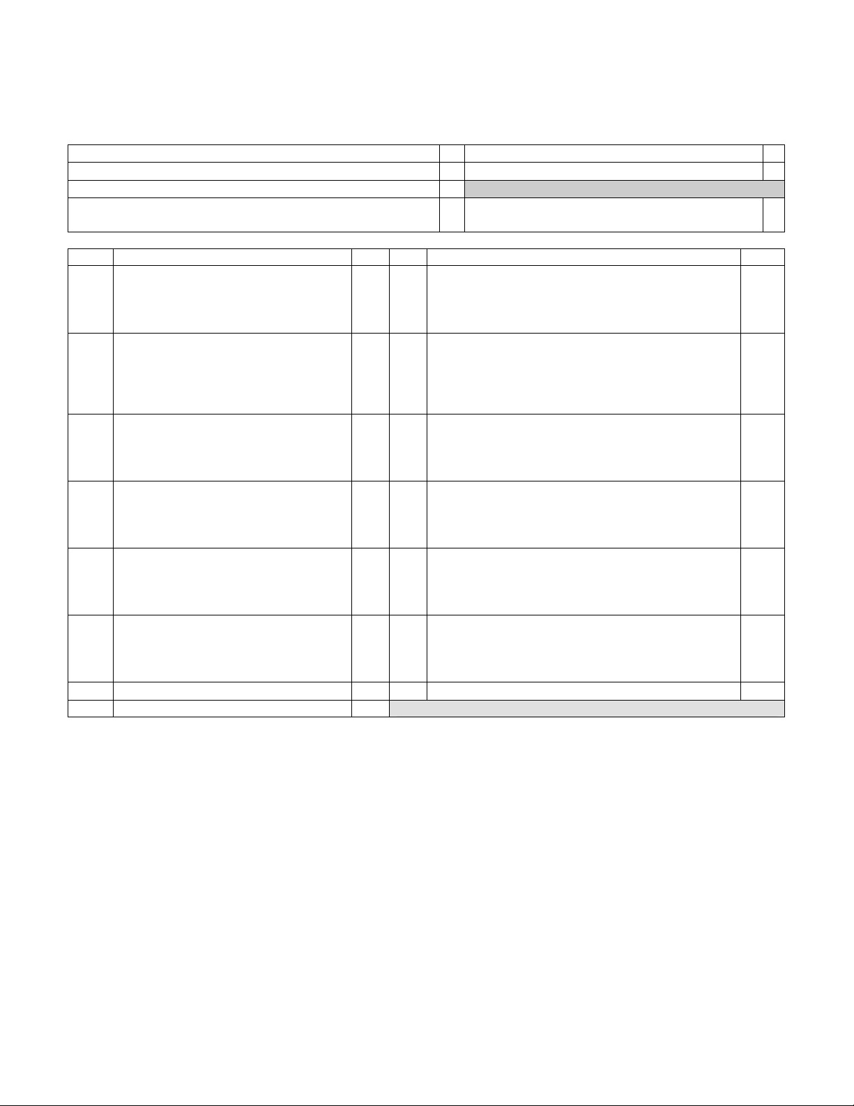
1. MCR120-F Radiator installation
2. MCP650 Pump installation
The radiator/fan assembly fits into any exhaust opening designed to
receive a 120mm case fan. Depending on the case design, the radiator
can be installed in the back of the case (most common) as shown fig 1,
or the front of the case. Please refer to the separate installation guide
provided in appendix to fasten the radiator to the chassis.
Back
of
Chassis
Snap-rivet
120mm fan
6-32 x 3/8" philips
MCR120 Radiator
Figure 1
Front
of
Chassis
Preferable position is at the bottom of the chassis. However, the
pump can operate in any position. For optimum safety, the pump
can be bolted to the chassis. TIP! Do not peel-off the protective
sticker until you are satisfied with the position of the pump, as
subsequent removal is destructive to the foam gasket.
The pump’s inlet and outlet are ½” in outside diameter. A
length of ½” ID tubing is pre-installed on the pump inlet and will be
connected directly to the reservoir ½” barb discharge. The pump
discharge is pre-installed with a 3/8” barb adapter and connects to
the rest of the circuit.
1½ ft.
Snap-rivet
6-32 x 3/8" philips
120mm fan
MCR120 radiator
Figure 2
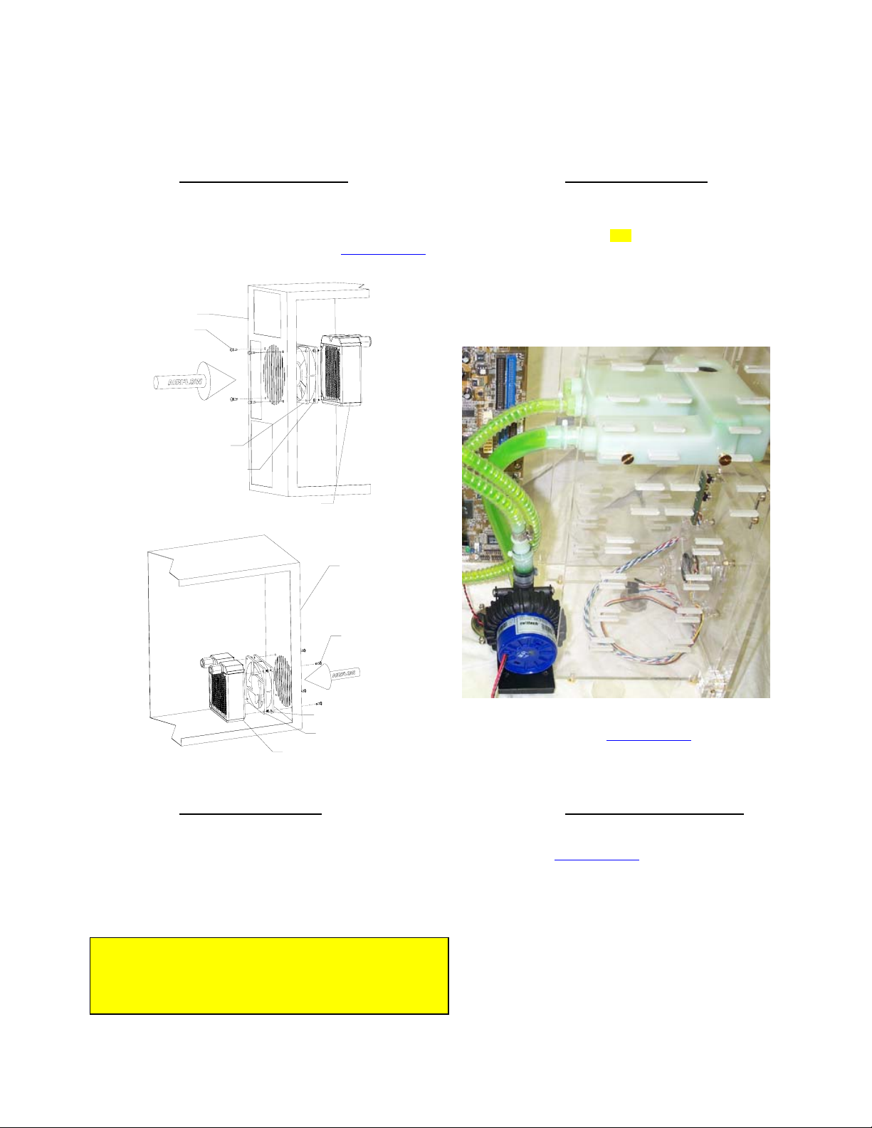
3. Water-block(s) Installation
When provided in kit form, the MCW6000 series water-blocks
receive 2 ft. of pre-installed tubing at the inlet and outlet. In dual
processor kits, one of the water-blocks inlets is free of tubing so that
water-blocks may be installed in series.
Please refer to your specific model installation guide provided in
appendix to install your water-block to the motherboard.
TIP! For the mock-up installation, interposing a piece of
aper between the water-block and the processor will protect
both the cooler and the processor surfaces.
Figure 3
Please refer to the separate installation guide
for specific information regarding the installation of the pump.
provided in appendix
4. MCRES-525 reservoir installation
Install the MCRES-525 reservoir in the desired 5 ¼” bay,
following the installation guide
Uppermost drive bay is preferred, but not mandatory.
Remember when you fill-up the system that your circuit will
respond to the laws of communicating vases. If the radiator
for example is higher than the reservoir, you will want to hold
the reservoir higher than the radiator while filling it up so that
it doesn’t overflow, then close the fill-cap, then secure the
radiator in the desired bay.
Position the reservoir so that it protrudes approximately 1 ½”
outside of the case. Measuring the length of tube needed in
this position will give sufficient slack in the line so that you
can pull the reservoir enough to fill-it-up during maintenance
operations.
located in appendix.
Rouchon Industries, Inc., dbA Swiftech™ – 1703 E. 28th St, signal Hill, CA 90755, USA – T (562) 595-8009 – F (562) 595-8769 – All content
Copyright Swiftech 2004 – Last edited 9-27-04 – Subject to revision without notice - 7 of 40 -
Page 8
5. Cutting the tubing, & connecting components
Now that your mock-up installation is in place, it is time to cut segments of
tubing and connect the devices together.
In addition to the water-block pre-installed tubing, your kit comes with an
additional 4 feet of ½” OD tubing which is normally sufficient to
accommodate most configurations, including dual processors.
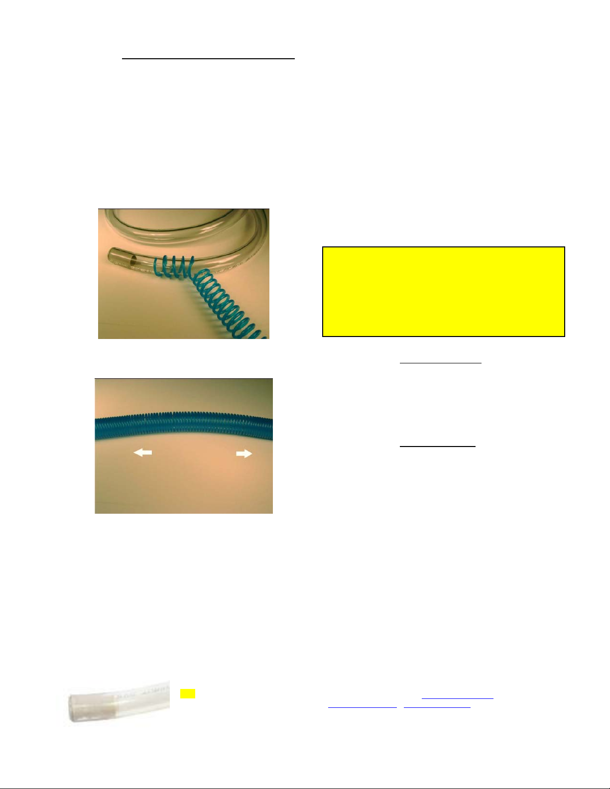
Your kit also comes with a 40” length of Coolsleeves
extended is sufficient to cover 6 feet of tubing. Use of these coils is mandatory in
order to prevent kinking and flattening of the tube over time.
Start by wrapping the included Coolsleeves™ coil around the 4-foot
piece of tube. Leave yourself enough Coolsleeves to wrap the waterblock(s) pre-installed tubing.
™ coils which, when
Wrap Coolsleeves™ around tubing
Figure 4
When attaching the tube to a quick-connect fitting,
rollback the coil by a couple of inches, as this will
give you a better grip onto the naked tube to insert
the tube into the fitting. The tube will go in freely for
the first ¼” and you will then feel a resistance: this is
the O-ring inside the fitting. Push
by twisting the tube back-and-forth for another ½”
until the tube reaches the tube-stop at the bottom of
the fitting. The tube is properly installed once the
visible extremity of the tube insert is flush with the
face of the quick-connect fitting. Then bring the coil
back to the face of the fitting.
Once everything is connected, you should then
adjust the Coolsleeves coil spacing: adjust to a wide
space between each coil (up to ¼” or more if
needed) when the tube is straight, and very close to
each other in tight bends (approximately 1/8
inch or less).
With everything in place, carefully double-check
each connection. If it all looks tight and secure
proceed to the next step.
TIP! Verify that each cooler will ‘hang’ naturally in very
close to its mounted position. If the stiffness of the tubing, or
the tight radius of the necessary bend, will not permit such,
then it may be necessary to externally support the tubing:
typically some strategically placed cable ties will facilitate this
restraint. This precaution is particularly important with AMD®
K7 class processors, but less so with Intel® Pentium® 4,
Xeon, or AMD® K8 class processors.
through the O-ring
th
of an
6. Preparing the coolant
Your kit comes with a 2 Oz (60ml) bottle of Swiftech’s specially
formulated HydrX
mixed with distilled or demineralized water only. Simply empty
the concentrated coolant into a 33 fl oz (1 liter) plastic bottle, and
complete filling with your distilled water. Your coolant is ready.
concentrated coolant. The product should be
Figure 5
Gather Coolsleeves
the tubing. This will allow Coolsleeves™ to expand to its natural pitch.
Tight radii sections require that coils be close to each other (1/8” spacing coil to
coil). In straight sections, coils can be spaced up to ¼” or more, coil to coil
Then, with one end of a tube connected to a startup component such
as the water-block for example, roughly estimate the length that you
will need to the next component, and cut the tube and coil squarely
with a pair of scissors. Work your way through the entire circuit in the
same fashion, until you are satisfied with the tube routing.
Quick-connect fittings: If you are going to a component featuring a
quick-connect fitting, make sure to allocate approximately ¾” of tube
to go into the fitting, and install a tube insert (shown below) at the
extremity of each tube.
™ towards the center of the tubing, then pull on the ends of
TIP! Rubbing the extremity of the
tube with a little bit of liquid soap will
greatly facilitate insertion of the tube
into a quick-connect fitting.
7. Filling up the circuit
Please refer to the MCRES-525 installation guide in appendix for
specifics on how to fill-up the system. In this paragraph, we will
discuss safety measures.
It is good practice to pre-test that your system is liquid-tight away
from sensitive electronic components. Two strategies can be
employed:
Dismount all the components that you installed in
the mock-up, and fill-up your system outside of
the case, or
Remove motherboard, VGA adapter, hard drives
and CD Rom (if any), from the chassis, which is
our preferred solution.
In either case, you will need to start-up your pump in order to
completely fill-up the system. Since your MCP650 is a 12Volts
pump feeding off the computer power-supply, you must be able
to start the PSU without it being connected to the motherboard.
While the Internet is full of references on how to short-out pin 14
and 15 of the ATX connector to start up the PSU independently,
we really do not recommend this method. The safe and proper
method to start-up the PSU independently is to use a powersupply tester. A wide variety of these common devices is
available on the Internet (google key word: “PSU tester”), and
among Swiftech resellers (www.frozencpu.com
www.Directron.com
,
, www.newegg,.com etc..)
Rouchon Industries, Inc., dbA Swiftech™ – 1703 E. 28th St, signal Hill, CA 90755, USA – T (562) 595-8009 – F (562) 595-8769 – All content
Copyright Swiftech 2004 – Last edited 9-27-04 – Subject to revision without notice - 8 of 40 -
Page 9
8. Final installation
Once your system has been tested for leaks, it is now time to proceed with the final installation. Assuming that you followed our preferred
method, re-install the motherboard inside of the chassis, being careful to keep the water-blocks out of the way (some wire-ties or rubber
bands strategically placed are a good help). Then perform the final water-block installation using thermal grease, in accordance with your
specific water-block model installation guide (see appendix).
Figure 6
Figure 6 above illustrates an installation using the MCRES-525 reservoir, MCP650 pump, MCW6000-A water-block, MCW20 chipset cooler,
MCW50 VGA cooler, and MCR120 radiator mounted externally with the MCB-120 “Radbox”
Rouchon Industries, Inc., dbA Swiftech™ – 1703 E. 28th St, signal Hill, CA 90755, USA – T (562) 595-8009 – F (562) 595-8769 – All content
Copyright Swiftech 2004 – Last edited 9-27-04 – Subject to revision without notice - 9 of 40 -
Page 10
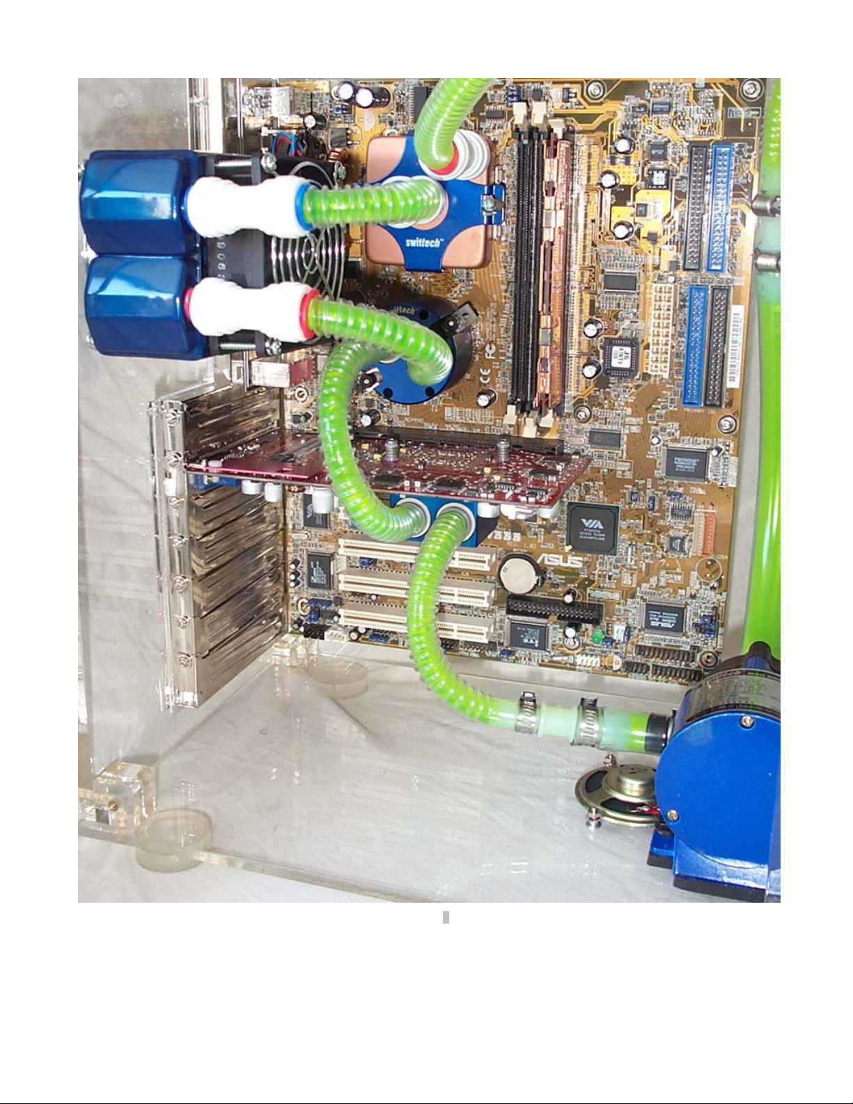
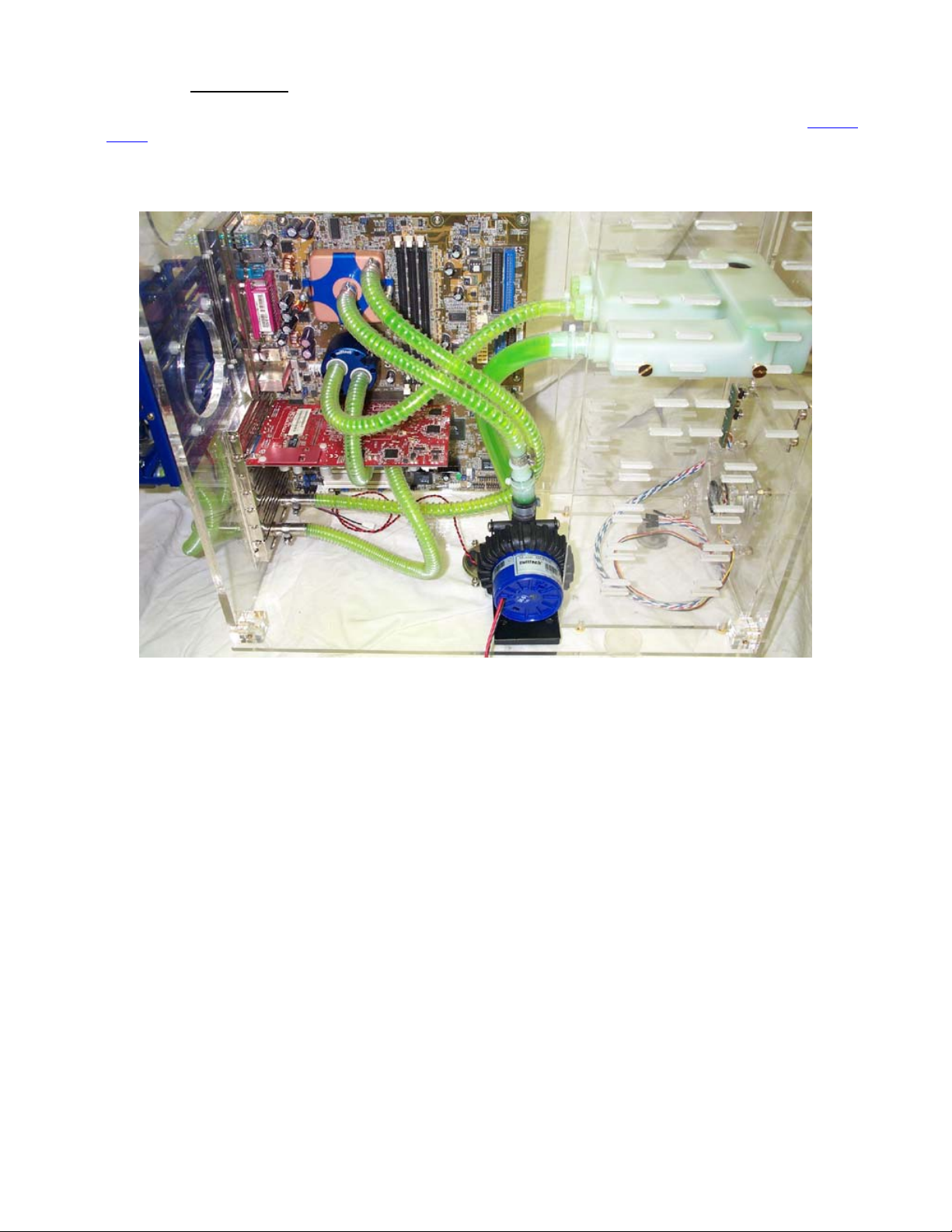
Figure 7
Figure 7 above illustrates a final installation, showing the MCR80-F2 radiator in place, the MCW6000 CPU cooler, the MCW50 VGA cooler, the
MCW20 chipset cooler, and an earlier MCP600 pump. Notice how the Coolsleeves coils allow tight bends, keeping a “clean” uncluttered
arrangement of the circuit. In this particular chassis, the radiator is positioned slightly lower relative to the CPU. As a result, we installed the
components in the following sequence: VGA cooler -> Chipset cooler -> Radiator -> CPU cooler.
Rouchon Industries, Inc., dbA Swiftech™ – 1703 E. 28th St, signal Hill, CA 90755, USA – T (562) 595-8009 – F (562) 595-8769 – All content
Copyright Swiftech 2004 – Last edited 9-27-04 – Subject to revision without notice - 10 of 40 -
Page 11
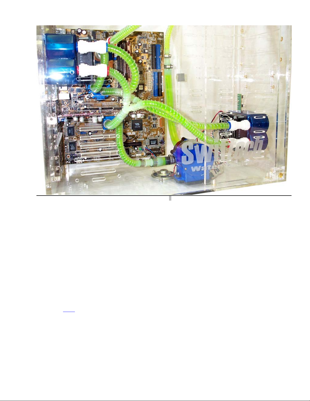
Figure 8 shows a dual radiator setup. This particular setup was chosen to illustrate how to overcome the apparent difficulty of connecting two
radiators located opposite to one another in a chassis: one radiator in the back, and one radiator in the front. Such chassis configuration is
among the most commonly found in today’s mid-tower cases.
Notice how the radiators are setup in a parallel connection: from the MCW50 VGA cooler discharge, the tube is split into two sections, using a
Y connector. Each branch of the “Y” is then connected to each radiator inlet. Then the radiator discharge tubes rejoin into another “Y”
connector which goes to the MCW20 chipset cooler inlet, thus resuming the circuit. In this particular example, the sequence in which
components are connected to one another was chosen purely for convenience in tube routing, and dictated by the respective positions of
these components.
From a performance standpoint there is very little performance to be gained from strictly controlling the component sequence: the maximum
delta T (difference in temperature) between any two points of the liquid cooling circuit does not exceed 1ºC. Whenever possible, performance
oriented users will typically want to route the radiator discharge(s) tube(s) to the inlet of the CPU cooler, since the fluid exiting the radiators is
always the coolest.
Figure 8
III. Draining the system
You will need to disconnect a line from one of the lowermost components. Procure a bucket large enough to receive approximately
1 liter of fluid, and place the bucket underneath the connection that you intend to “break”. Disconnect the line, and place both ends
into the bucket.
Open up the fill-cap from the MCRES-525. This will allow most of the fluid to escape.
A cleaner and much more convenient method consists in incorporating a drain assembly into the circuit during initial installation.
See TV500
drain assembly below.
IV. Periodic maintenance
Every 6 months: dust off the radiator fins and fan. You can use a can of compressed air for example, available in most
electronic supply stores. If you live in a very dusty area, you should perform this task at closer intervals. It is essential to
the optimum performance of your cooling system.
Inspect the level of liquid inside the circuit, and refill if necessary. Evaporation in this closed circuit is extremely limited, but
still present due to microscopic porosity in the vinyl lines.
Rouchon Industries, Inc., dbA Swiftech™ – 1703 E. 28th St, signal Hill, CA 90755, USA – T (562) 595-8009 – F (562) 595-8769 – All content
Copyright Swiftech 2004 – Last edited 9-27-04 – Subject to revision without notice - 11 of 40 -
Page 12

V. Available accessories
Improve performance with a second radiator:
MCR120-F Radiator assembly
Part # MCR120-F, includes radiator, 120mm
fan, retention screws, quick-connect fittings
Part # MCB-120 “Radbox”
(http://www.swiftnets.com/products/MCB-120.asp)
TV500 Drain assembly
MCR120-FRB™ Complete 120mm Radiator/fan/Radbox
http://www.swiftnets.com/products/mcw50.asp for
kit - BLUE
VGA Cooling
specifications
Please go to:
MCB-PT "Pass-thru" accessories
for 1/2" OD (3/8" ID) tubing
Chipset Cooling
Please go to: http://www.swiftnets.com/products/mcw20.asp for
1/2" (Tube OD) Flush Assembly, including
1/2" Tube quick-connect T, and 1/2" quick-
connect ball valve. A useful accessory for
users who empty their system often. Can
also be used as a fill T (without reservoir).
specifications
Part # MCW20
Rouchon Industries, Inc., dbA Swiftech™ – 1703 E. 28th St, signal Hill, CA 90755, USA – T (562) 595-8009 – F (562) 595-8769 – All content
Part # MCW50
Copyright Swiftech 2004 – Last edited 9-27-04 – Subject to revision without notice - 12 of 40 -
Page 13

VI. Appendix: Individual Component Installation guides
- INTENTIONNALY LEFT BLANK -
Rouchon Industries, Inc., dbA Swiftech™ – 1703 E. 28th St, signal Hill, CA 90755, USA – T (562) 595-8009 – F (562) 595-8769 – All content
Copyright Swiftech 2004 – Last edited 9-27-04 – Subject to revision without notice - 13 of 40 -
Page 14

Packing list
MCR120 radiator 1 Tube inserts 2
Snap-rivet 4 120x25mm fan 1
6-32” x 3/8” Philips screw 4 Quick-connect fittings 2
Back
of
Chassis
Snap-rivet
Front
of
Chassis
Snap-rivet
120mm fan
6-32 x 3/8" philips
MCR120 Radiator
Figure 7 - Back of chassis installation
MCR120 radiator
Figure 8 – Front of chassis installation
6-32 x 3/8" philips
120mm fan
Preamble
The MCR120-F
chassis. This configuration is preferred to optimize cooling of the CPU. In effect, if the fan flow direction were reversed, it would use heated air
inside of the chassis, which is usually 3°C (at best) and up to 10°C hotter than that of the ambient air outside of the chassis.
1. Installation
Depending where a 120mm fan opening is available, the MCR120-F can be installed as shown in Figure 1 (back of the chassis), or Figure 2 (front
of the chassis). Due to the wide variety of chassis configurations, Swiftech cannot guarantee that this assembly will bolt into any chassis without
some modifications. However, an external mounting solution is optionally available with the MCB120
and-play installation with most desktop computers.
2. Bleeding
For bleeding purposes, the preferred radiator orientation is with inlet and outlet pointing up as shown above. Nonetheless, the radiator can also be
installed at 90
bleeding process. For this reason, it might be more convenient to fasten the radiator to the chassis after the circuit has been fully filled and bled.
ships with the fan pre-assembled to the radiator. It has been configured so that the fan will draw fresh air from outside of the
“Radbox” which will usually allow a plug-
° or 180°. In such cases, simply rotate the radiator back upwards to allow the air trapped inside to escape during the filling and
3. Using quick-connect fittings
If you are using soft vinyl tubing, you must also use the provided tube
inserts. Cut the extremity of the tube
tube insert into the tube as shown in Figure 3.
Rouchon Industries, Inc., dbA Swiftech™ – 1703 E. 28th St, signal Hill, CA 90755, USA – T (562) 595-8009 – F (562) 595-8769 – All content
Copyright Swiftech 2004 – Last edited 9-27-04 – Subject to revision without notice - 14 of 40 -
squarely, and fully engage the
Figure 9
Page 15
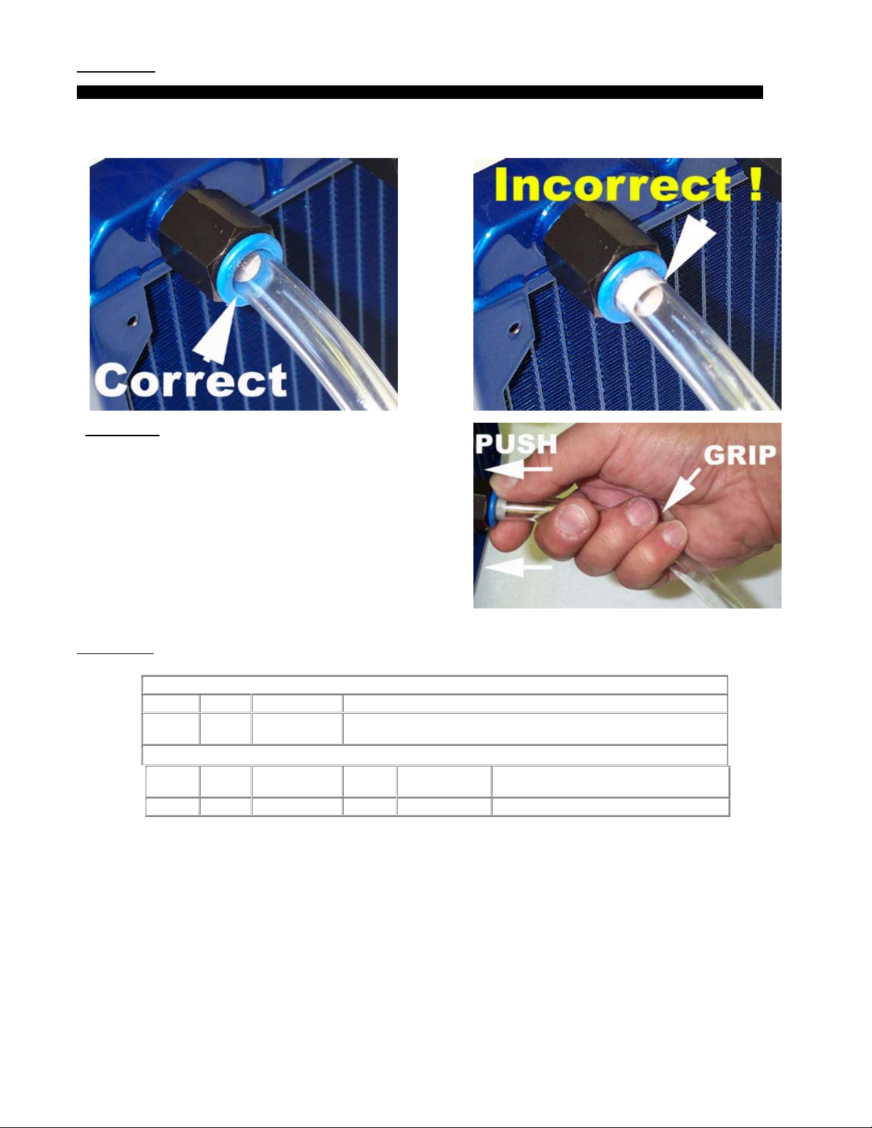
Tube insertion
TIP! Rubbing the extremity of the tube with a little bit of liquid soap will greatly facilitate insertion of the tube into the quick-connect fitting.
Insert the tube into the quick-connect fitting. The tube will go in freely for the first ¼” and you will then feel a resistance: this is the O-ring inside of
the fitting. Push
through the O-ring by twisting the tube back-and-forth for another ½” until the tube reaches the tube-stop at the bottom of the fitting.
Tube removal
Firmly grip the tube in the cradle formed by three fingers, and push
against the blue collet with thumb and index fingers. This will
disengage the tube from the fitting. Correct position of the hand
and fingers is shown in Figure 6.
4. Specifications
Thickness Height Core width Inlet Outlet tube size
0.98"
(25mm)
Voltage
(V)
7.0-13.8 .20 2100 72.4 .134 34
Figure 10
5.9"
(157mm)
Current
(mA)
Radiator Assembly Dimensions - Part # MCR120-FB
5.00"
(133mm)
Fan Specifications - Part # WFB1212M
Speed
(RPM)
Volume
(CFM)
1/2" (tube OD) quick connect adapters included
Static pressure
(InH20)
Figure 11
Figure 12
Sound Noise
(dbA)
Rouchon Industries, Inc., dbA Swiftech™ – 1703 E. 28th St, signal Hill, CA 90755, USA – T (562) 595-8009 – F (562) 595-8769 – All content Copyright
Swiftech 2004 – Last edited 9-27-04 – Subject to revision without notice - 15 of 40 -
Page 16

Parts list
Parts QTY PARTS QTY
MCB-120™ Housing assembly 1 Coolsleeves™ 20” (*)
Retention hardware (screws, etc.) 1 PCI Pass-Thru kit 1 (*)
½” tubing 2’ (*) Worm drive clamps 4 (*)
(*) Only included with complete kit
1. PCI pass-thru kit installation
o Insert the PCI bracket into an available opening, and secure it to the chassis.
o Insert your fan electrical connector through the slotted hole of the PCI bracket now. Only 3-pin connectors (the type that
connect to the motherboard) are small enough to pass through the slotted hole. 4-pin Molex connectors (the type that
connect to your power supply) will require that the terminals be removed from the Molex housing first.
o From inside of the chassis, insert the pass-thru adapters through each hole of the PCI bracket. The threaded portion of
the adapters should be exposed outside of the case.
o Screw the nuts to the adapters. The nuts are designed to slightly overlap the edges of the PCI chassis opening, to
provide a more secure installation.
2. Housing / fan & radiator installation: please refer to diagram page 2.
Rouchon Industries, Inc., dbA Swiftech™ – 1703 E. 28th St, signal Hill, CA 90755, USA – T (562) 595-8009 – F (562) 595-8769 – All content Copyright
Swiftech 2004 – Last edited 9-27-04 – Subject to revision without notice - 16 of 40 -
Page 17
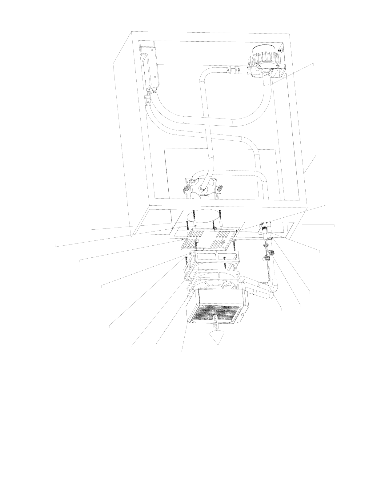
Pump Inlet
1/2" ID tubing
Chassis
MCB-120
holding plate
1/2" Nylon spacer (use as needed to provide clearance
with side panel) or alternatively use (1) or (2) provided nylon washers
6-32 x 1" machine screw (fine thread)
Use alternate 6-32 x 1 1/2" for thick acrylic panels
or provided 4-40 x 1 1/4" with nuts and washers for 60mm fan openings
bracket
Custom PCI
#4 x 1/4"
(course thread)
sheet metal screw
nut
6-32 nylon
Pass-thru adapter
Pass-thru nut
hose clamp
#4 worm-drive
Fan power
connector thru
PCI bracket
120x25mm
fan
Radiator
metal screw
(coarse thread)
#6 x 1 1/4" sheet
housing
MCB-120
Rouchon Industries, Inc., dbA Swiftech™ – 1703 E. 28th St, signal Hill, CA 90755, USA – T (562) 595-12009 – F (562) 595-8769 – All content
Copyright Swiftech 2004 – Last edited 9-11-04 – Subject to revision without notice - 17 of 40 -
Page 18
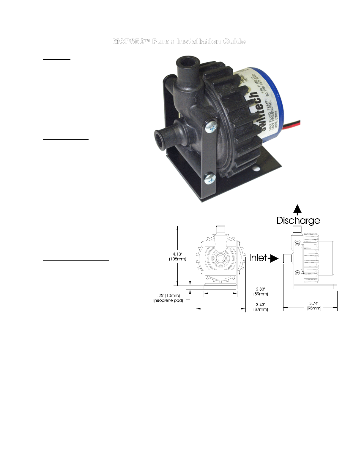
1. General Use
The MCP650 pump is a magnetically driven
centrifugal pump featuring a 12 V DC motor. It
requires no maintenance when used with demineralized water and the appropriate anti-fungal
additives. We recommend using 5% Swiftech’s
HydrX
as an additive. The pump is designed to be
connected to your computer power supply using the
standard Molex 4 pin connectors.
The MCP650 pump is not submersible.
2. Physical installation
Determine the best location for your pump by
observing how the tubing will be routed to the
rest of the circuit. Sharp bends in the tubing
should always be avoided to prevent kinks,
which will reduce or completely prevent flow of
the cooling fluid.
In general, we recommend installation of the
pump at the bottom of the chassis.
The base of the pump features a soft neoprene
pad coated with strong adhesive material. Once
an appropriate location for the pump has been
determined, simply peel-off the pad’s protective
paper, and press the pump against the chassis
surface. The surface should be clean, and non
greasy. Thru-bolts are also provided for
permanent installation, and require drilling holes
in the chassis (see permanent installation page
2).
3. Pump operating precautions:
The MCP650 pump should never be run dry, even
for a quick test
with fluid before you start operating it (see warranty
note *).
Use of coloring die or fluorescent additives
containing particulate fillers will cause excessive wear
to the pump’s impeller bearing (see warranty note **).
. You should always prime the pump
Do not utilize small diameter or flow restrictive fittings in the pump inlet line. Minimum line inner diameter is 3/8”. An example would be a
reservoir with ¼” fittings. This will cause the pump impeller to cavitate, lose prime, stop pumping and damage the pump (see warranty note ***).
Rouchon Industries, Inc., dbA Swiftech™ – 1703 E. 28th St, signal Hill, CA 90755, USA – T (562) 595-12009 – F (562) 595-8769 – All content
Copyright Swiftech 2004 – Last edited 9-11-04 – Subject to revision without notice - 18 of 40 -
Page 19

Connecting the pump to the circuit:
The pump’s inlet and outlet are ½” in outside diameter. An adapter kit is
available (included with all our complete kits) to connect the MCP650 to a circuit
using ½” ODx3/8”ID tubing. This kit consists in:
tubing and two reducers to make the transition to the ½”ODx3/8”ID circuit.
TIP: when connecting the MCP650 pump to a ½”ODx3/8”ID circuit, always use
the longest possible ¾”ODx½”ID tube section at the inlet.
1 foot supply of ¾”ODx½”ID
4. Performance & Specifications
WARRANTY:
Guarantee consists of replacing defective parts with new or reconditioned parts. Guarantee is considered void in case of
(*)(**)(***), handling or negligence on the part of user. Original invoice showing date and place of purchase is required for exercise of the
warranty. (*) WARNING: DO NOT ATTEMPT TO RUN THIS PUMP DRY. THIS WILL CAUSE IMMEDIATE AND PERMANENT DAMAGE TO THE PUMP. (**)
EXCESSIVE WEAR DUE TO INNAPROPRIATE FLUIDS. (***) EXCESSIVE RESTRICTION TO THE PUMP’S INLET
This product is guaranteed for a period of 24 months from date of purchase for defects in material, and workmanship.
Nominal voltage 12 V DC
Operating voltage range 6 to 14 VDC
Nominal power (@ 12 V) 24 W
Nominal current (@ 12 V) 2 amps
Motor type
Maximum head 10 ft (3.1 m)
Maximum discharge ~ 317 GPH (1200 LPH)
Connection size ½" barbs
Maximum pressure 50 PSI (3.5 BAR)
Temperature range 32 °F to 140°F (0 °C to 60 °C)
Electrical connector Molex 4 pin
Weight 1.4 LB (650 gr.)
Impeller Housing material Noryl®
Our noise measurement (non
lab environment)
Brushless, microprocessor
controlled
33 ~ 34 dBA in a quiet room @ 2'
improper use
DISCLAIMER: Swiftech assumes no liability whatsoever, expressed or implied, for the use of this product, and more specifically for
any, and all damages caused by the use of this product to any other devices in a personal computer, whether due to product failure,
leak, electrical shorts, and or electro-magnetic emissions.
5. Permanent installation to the chassis
Rouchon Industries, Inc., dbA Swiftech™ – 1703 E. 28th St, signal Hill, CA 90755, USA – T (562) 595-8009 – F (562) 595-8769 – All
content Copyright Swiftech 2004 – Last edited 9-27-04 – Subject to revision without notice - 19 of 40 -
Page 20

6. MCP650 – Exploded view
Rouchon Industries, Inc., dbA Swiftech™ – 1703 E. 28th St, signal Hill, CA 90755, USA – T (562) 595-8009 – F (562) 595-8769 – All
content Copyright Swiftech 2004 – Last edited 9-27-04 – Subject to revision without notice - 20 of 40 -
Page 21

PARTS LIST – BARBED ADAPTERS ARE SOLD SEPARATELY
Parts QTY PARTS QTY
MCRES-525™ Reservoir 1 Retention screws 4
This product is intended for expert users. Please consult with a qualified technician for installation. Improper installation may result in
damage to your components. Swiftech assumes no liability whatsoever, expressed or implied, for the use of these products, nor their
installation. The following instructions are subject to change without notice. Please visit our web site at www.swiftnets.com
updates.
The MCRES-525™ reservoir is designed to be installed in a 5 ¼” drive bay. It features three 3/8” threaded ports (standard NPT thread)
to accommodate a number of configurations (see * Swiftech fittings). The port usage is defined as follows:
The following guide assumes that all liquid cooling components in your system, such as radiator, pump, and water-block(s) have been
already installed, and the graphic below shows an overview of a typical installation.
Fill-cap & o-ring 1 Port plug 1
for
(1) Discharge port located at the “stepped-down” compartment. This port must ALWAYS be connected to the
pump inlet for the MCRES-525™ to operate properly.
(2) Inlet ports can be used interchangeably: in “single inlet” configuration (the most common), or “dual inlet”
configuration when devices are returning to the reservoir in parallel. One port plug is provided to seal one of the
inlets in order to accommodate the most common “single inlet” configuration.
Important! All fittings (except DP-11) require sealant: plumbers tape, or plumbers goop (preferred)
A6-8
1/2" barb to 3/8" NPT, for 1/2"
Inner diameter tubing (3/4" or
5/8" outer diameter) – Order
Separately
Rouchon Industries, Inc., dbA Swiftech™ – 1703 E. 28th St, signal Hill, CA 90755, USA – T (562) 595-8009 – F (562) 595-8769 – All
content Copyright Swiftech 2004 – Last edited 9-27-04 – Subject to revision without notice - 21 of 40 -
A6-6
3/8" barb to 3/8" NPT, for
3/8" Inner diameter tubing
(1/2"outer diameter) – Order
separately
Swiftech Fittings & Spare parts
PI011623S
3/8” NPT to ½” tube (outer
diameter) quick-connect
fitting – Order separately
DP-11
Fill-cap & o-ring
Included
P6N
3/8” NPT Port
plug
Included
Page 22

Installation guidelines
Figure 1: Always leave sufficient slack in the lines to pull enough
of the reservoir out of the drive bay and uncover the fill port.
Figure 2: You can start filling up the reservoir while it is in the drive
bay, using a household funnel.
the reservoir as needed.
the reservoir to its minimum operating level, as shown figure 3.
Then, start-up the pump and top-off
With this method, you will be able to fill-up
Figure 3: The minimum operating fluid level is at the mould
parting line.
Figure 5: Desired (Maximum) operating fluid level Figure 6: Once full, secure the reservoir to the drive-bay with the
Figure 4: If possible or desired, you can also fill the reservoir outside
of the chassis. Tipping it steeply at an angle will allow you to fill-it up at
the maximum operating level as shown figure 5. Do not forget to close
the fill-cap before you re-install the unit into the drive bay!
provided screws.
Installation is complete!
Rouchon Industries, Inc., dbA Swiftech™ – 1703 E. 28th St, signal Hill, CA 90755, USA – T (562) 595-8009 – F (562) 595-8769 – All content
Copyright Swiftech 2004 – Last edited 9-27-04 – Subject to revision without notice - 22 of 40 -
Page 23

Installation guide for Pentium 4 processors
Parts list
Parts QTY PARTS QTY
MCW6000-P™ water-block 1 Retention clips 2
This product is intended for expert users. Please consult with a qualified technician for installation. Improper installation may result in
damage to your components. Swiftech assumes no liability whatsoever, expressed or implied, for the use of these products, nor their
installation. The following instructions are subject to change without notice. Please visit our web site at www.swiftnets.com
updates.
Worm drive clamps 2 SP4 hold-down plate 1
DISCHARGE
3
1
INLET
for
ITEM NO. QTY. PART NO. DESCRIPTION
1 1 S478 Intel Pentium 4 socket 478 motherboard and processor
2 1 MCW6000-P-with-bracket MCW6000-P water-block assembly
a 1 MCW6000-FLAT MCW6000 waterblock flat base
b
1 SP4-Bckt SP4 Hold-down plate for Intel Pentium 4 and Xeon
3 2 SC478 Pentium 4 spring clip
1. Preparing your Motherboard
Remove the existing heat sink
Carefully clean the CPU.
Lightly coat the CPU with thermal compound. We recommend high quality thermal compound such as Arctic Silver or equivalent.
Application will vary depending on the type of processor. We recommend visiting www.arcticsilver.com for detailed instructions.
2. Water-block orientation
For ease of operations during bleeding, the outlet should always be at the highest point (while system is standing upright):
Rouchon Industries, Inc., dbA Swiftech™ – 1703 E. 28th St, signal Hill, CA 90755, USA – T (562) 595-8009 – F (562) 595-8769 – All content
Copyright Swiftech 2004 – Last edited 9-27-04 – Subject to revision without notice - 23 of 40 -
Page 24

3. Water-block installation:
Step 1
Center the water-block inside the retention
frame. Put both clips in place for the next
step, by simply slipping the hook of each
clip into the holes of the retention frame.
4. Connecting the water-block(s) to the cooling circuit:
Carefully identify the direction of the flow in your circuit. For the MCW6000 to operate properly,
the fitting located at the center of the water-block
5. Attaching the tubes:
Step 2
While maintaining the opposite side of the
block to prevent it from tipping over, push
down on the clips’ thumb-tab until the hook
catches the hole in the retention frame.
MUST BE USED AS THE INLET.
Step 3
Keep maintaining pressure on the block to
prevent it from tipping over, and hook-down
the second clip.
Installation is complete!
The MCW6000™ ships with 2’ of tube already clamped to inlet and outlet.
6. Alternate connections:
The MCW6000™ can also be used with optional quick-connect fittings (fig.5), or regular wormdrive hose clamps (fig. 4).
7. Type of Coolant:
Being entirely made of copper, the MCW6000™ may be used with pure water, and does not
necessitate the use of anti-corrosion agents. The use of an algaecide is nonetheless
recommended in any liquid cooling system, and our HydrX™ additive also performs such
function.
8. Final inspection:
Once the installation is completed, it is always a good idea to test the circuit for leaks, prior to
powering up the computer.
bow the top of the housing and render the block unusable (and will void your warranty).
Maximum pressure allowable for testing is 25 psi (1.7 bar)
Do not test the water-block using city water pressure. This will
Tubes attached with the included worm-
drive clamps
Optional quick-connect fittings
Rouchon Industries, Inc., dbA Swiftech™ – 1703 E. 28th St, signal Hill, CA 90755, USA – T (562) 595-8009 – F (562) 595-8769 – All content
Copyright Swiftech 2004 – Last edited 9-27-04 – Subject to revision without notice - 24 of 40 -
Page 25

A
Installation guide for Xeon (400 & 533 MHz FSB) processors
Parts QTY PARTS QTY
MCW6000-PX™ water-block 1 6-32 x 1 ¼” Philips screws 4
Worm drive clamps 2 Springs 4
SP4 hold-down plate 1 Standoffs 4
4-40 Nylon retaining washers 4 Black fiber washers 8
Locknuts 4
This product is intended for expert users. Please consult with a qualified technician for installation. Improper installation may result in damage to
your components. Swiftech assumes no liability whatsoever, expressed or implied, for the use of these products, nor their installation. The
following instructions are subject to change without notice. Please visit our web site at www.swiftnets.com
The MCW6000-PX can be installed using two different methods:
Using the spring-loaded screws and standoffs included with the water-block (fig. 1 below)
Using the plastic retention frames and spring clips included with most motherboards (fig. 2 page 2)
6
7
Parts list
for updates.
ITEM NO. PART NO. DESCRIPT ION
1DUAL-XEON-BOARD Motherboard
2 STANDOFF swtainless steel hexagonal 1/4" standoff
3 6-32-LOCKNUT 6-32 LOCKNUT
4 FW140X250X0215FB BLK black fiber washer
5 MCW6000-P-with-bracket MCW6000-P water-block assembly
a MCW6000-FLAT MCW6000 waterblock flat base
b SP4-Bckt SP4 Holdi ng plate for Intel Pentiu m 4 and Xeon
6 91772A154-phil6x32x1.125 6-32 x 1 1/4" philips scfrew
7 70750 0.042 diam Heavy Duty spring
8 4-40 nylon retaining washer 4-40 nylon retaining washer
8
FLUID INLET
FLUID DISC HARGE
2
1
ssembly using our
spring-loaded screws
and standoffs
4
3
Figure 1
Rouchon Industries, Inc., dbA Swiftech™ – 1703 E. 28th St, signal Hill, CA 90755, USA – T (562) 595-8009 – F (562) 595-8769 – All content
Copyright Swiftech 2004 – Last edited 9-27-04 – Subject to revision without notice - 25 of 40 -
Page 26
A
16 PART NO. DESCRIPTION
1DUAL-XEON-BOARD Motherboard
2 RETENTION Plastic retention frame, included with motherboard
3 XEON-CLIP Xeon clip included with motherboard
4 MCW6000-P-with-bracket MCW6000-P water-block assembly
a MCW6000-FLAT MCW6000 waterblock flat base
b SP4-Bckt Hold-down plate for Intel Pentium 4 and Xeon
3
SSEMBLY USING PLASTIC
FRAME AND SPRING CLIPS
INCLUDED WITH MOTHERBOARD
FLUID INLET
4b
4a
2
1. Preparing your Motherboard:
Remove the existing heat sink
Carefully clean the CPU.
Lightly coat the CPU with thermal compound. We recommend high quality thermal compound such as Arctic Silver or equivalent.
Application will vary depending on the type of processor. We recommend visiting www.arcticsilver.com for detailed instructions.
FLUID DISCHARGE
1
Figure 2
2. Water-block orientation:
For ease of operations during the filling and bleeding procedures, the outlet should always be at the highest point (while the computer
system is standing upright):
3. Water-block installation:
The MCW6000-PX can be installed using two different methods (also see figure 1 and 2):
Rouchon Industries, Inc., dbA Swiftech™ – 1703 E. 28th St, signal Hill, CA 90755, USA – T (562) 595-8009 – F (562) 595-8769 – All content
Copyright Swiftech 2004 – Last edited 9-27-04 – Subject to revision without notice - 26 of 40 -
Page 27
Using the spring-loaded screws and standoffs included with the water-block (fig. 1), or
Using the plastic retention frames and spring slips included with most motherboards
You may use either method at your convenience. For installation with our own spring loaded
screws, follow the instructions below. For installation with Intel’s spring clips, follow the
instructions included in your motherboard manual.
(fig. 2)
4. Installation with spring loaded screws:
emove the motherboard from the chassis, and remove the stock retention plastic
R
frames to expose the mounting holes.
Install the standoffs though the holes, using fiber washers and locknuts as shown in
figure 1.
Tighten the standoffs as shown figure 3, using a ¼” socket tool to drive the standoff,
and a small
not to exceed 16 in. lbs. In other words just tight, without excessive torque,
otherwise the standoff stem may snap.
Tighten the spring-loaded screws in a crisscross pattern until the screws bottom out
into the standoff. Once there, do not attempt to lock the screws any further, or they
will jam into the standoff, and could prove difficult to remove if you ever need to
uninstall the heatsink.
Water-block installation is now complete.
5. Connecting the water-block(s) to the cooling circuit:
Carefully identify the direction of the flow in your circuit. For the MCW6000 to operate properly, the fitting
located at the center of the water-block
environments, connect the two blocks in series: For example: pump discharge to inlet of processor 1,
discharge of processor 1 to inlet of processor 2, and discharge of processor 2 to radiator.
6. Attaching the tubes:
The MCW6000™ ships with 2’ of tube already clamped to inlet and outlet.
7. Alternate connections:
The MCW6000™ can also be used with optional quick-connect fittings (fig.5), or regular worm-drive hose
clamps (fig. 4).
pair of pliers to prevent the locknut from spinning. Torque value should
MUST BE USED AS THE INLET. In multi-processor
Figure 3
Figure 4
Tubes attached with worm-drive
clamps
8. Type of Coolant:
Being entirely made of copper, the MCW6000™ may be used with pure water, and does not necessitate
the use of anti-corrosion agents. The use of an algaecide is nonetheless recommended in any liquid
cooling system, and our HydrX™ additive also performs such function.
9. Final inspection
Once the installation is completed, it is always a good idea to test the circuit for leaks, prior to powering up
the computer. Do not test the water-block using city water pressure. This will bow the top of the
housing and render the block unusable (and will void your warranty).
testing is 25 psi (1.7 bar)
Rouchon Industries, Inc., dbA Swiftech™ – 1703 E. 28th St, signal Hill, CA 90755, USA – T (562) 595-8009 – F (562) 595-8769 – All content
Copyright Swiftech 2004 – Last edited 9-27-04 – Subject to revision without notice - 27 of 40 -
Maximum pressure allowable for
Figure 5
Optional quick-connect fittings
Page 28

Installation guide for Xeon “Nocona” (800MHz FSB) processors
Parts list
Parts QTY PARTS QTY
MCW6000-NX™ water-block 1 6-32 x 7/8” Philips screws 4
Worm drive clamps 2 .600 x .250 Nylon spacer 4
This product is intended for expert users. Please consult with a qualified technician for installation. Improper installation may result in damage to
your components. Swiftech assumes no liability whatsoever, expressed or implied, for the use of these products, nor their installation. The
following instructions are subject to change without notice. Please visit our web site at www.swiftnets.com
SP4 hold-down plate 1 4-40 Nylon retaining washers 4
for updates.
7
6
9
11
10
1
3
5
4
ITEM NO. QTY. PART NO. DESCRIPTION
1 1 S604-NOCONA Motherboard & CPU assembly
3 1 spring-backplate retention spring (provided by motherboard vendors)
4 1 chassis
5 4 STANDOFF-0.187
6 1 MCW6000-FLAT MCW6000 waterblock flat base
7 1 SP4-Bckt SP4 Holding plate for Intel Pentium 4 and Xeon
9 4 90272A152-6-32x7-8-philips 6-32 x 7/8" (22mm) Philips screw
10 4 4-40 nylon retaining washer 4-40 nylon retaining washer
11 4 custom_spacer-r1 Nylon spacer .600 x .250 (15 x 6mm)
Figure 1
Rouchon Industries, Inc., dbA Swiftech™ – 1703 E. 28th St, signal Hill, CA 90755, USA – T (562) 595-8009 – F (562) 595-8769 – All content
Copyright Swiftech 2004 – Last edited 9-27-04 – Subject to revision without notice - 28 of 40 -
Page 29
9. Preparing your Motherboard
a. Remove the existing heat sink
b. Carefully clean the CPU.
c. Lightly coat the CPU with thermal compound. We recommend high quality thermal compound such as Arctic Silver or
equivalent.
10. Water-block orientation
For ease of operations during the filling and bleeding procedures, the outlet should always be at the highest point (while the
computer system is standing upright):
3. Water-block Installation
The MCW6000-NX water-block uses Intel’s validated retention spring, provided in accordance to Intel specifications by the motherboard
vendors. Installation of the water-block to the processor is identical to that of a standard heatsink, normally described in the
motherboard installation guide. Simply screw down all 4 Philips screws to the chassis standoffs as shown in Figure 1, and installation is
complete.
4. Connecting the water-block(s) to the cooling circuit
Carefully identify the direction of the flow in your circuit. For the MCW6000 to operate properly, the fitting
located at the center of the water-block
connect the two blocks in series: For example: from pump discharge to inlet of processor 1, discharge of
processor 1 to inlet of processor 2, and discharge of processor 2 to radiator.
MUST BE USED AS THE INLET. In multi-processor environments,
5. Attaching the tubes
When sold separately, the MCW6000™ ships with worm-drive type hose clamps. Secure the tubes as
shown in figure 2 (shown in this example with an AMD hold-down plate), and tighten
kits, the tubes are factory pre-installed with ear-clamps.
6. Alternate connections
The MCW6000™ can also be used with optional quick-connect fittings as shown in figure 3.
7. Type of Coolant
Being entirely made of copper, the MCW6000™ may be used with pure water, and does not necessitate the
use of anti-corrosion agents. The use of an algaecide is nonetheless recommended in any liquid cooling
system, and our HydrX™ additive also performs such function.
8. Final inspection
Once the installation is completed, it is always a good idea to test the circuit for leaks, prior to powering up
the computer.
and render the block unusable (and will void your warranty). Maximum pressure allowable for testing is
25 psi (1.7 bar)
Troubleshooting help is available on our web site at www.swiftnets.com, or by calling customer support at
562-595-8009.
Do not test the water-block using city water pressure. This will bow the top of the housing
firmly. When sold in
Figure 2
Tubes attached with the
included worm-drive clamps
Figure 3
Rouchon Industries, Inc., dbA Swiftech™ – 1703 E. 28th St, signal Hill, CA 90755, USA – T (562) 595-8009 – F (562) 595-8769 – All content
Copyright Swiftech 2004 – Last edited 9-27-04 – Subject to revision without notice - 29 of 40 -
Page 30
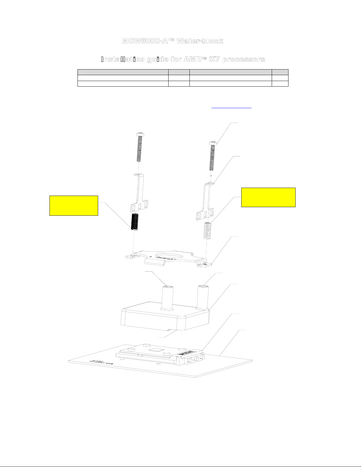
Installation guide for AMD K7 processors
Parts QTY PARTS QTY
MCW6000-P™ water-block 1 3T spring/clip assemblies 2
Worm drive clamps 2 SK7 hold-down plate 1
This product is intended for expert users. Please consult with a qualified technician for installation. Improper installation may result in damage to
your components. Swiftech assumes no liability whatsoever, expressed or implied, for the use of these products, nor their installation. The
following instructions are subject to change without notice. Please visit our web site at www.swiftnets.com
STIFF spring
black color
Parts list
for updates.
6-32 x 1.00" philips
3-T c lip
SOFT spring
metallic color
SK7 hold-down plate
INLET
Step side over "Cam box"
Figure 1
DISCHARGE
MCW6000-A water-block
socket "Cambox"
socket 462 motherboard
Rouchon Industries, Inc., dbA Swiftech™ – 1703 E. 28th St, signal Hill, CA 90755, USA – T (562) 595-8009 – F (562) 595-8769 – All content
Copyright Swiftech 2004 – Last edited 9-27-04 – Subject to revision without notice - 30 of 40 -
Page 31
1. Preparing your Motherboard
Remove the existing heat sink
Carefully clean the CPU.
Lightly coat the CPU with thermal compound. We recommend high quality thermal compound such as Arctic Silver or equivalent.
Application will vary depending on the type of processor. We recommend visiting www.arcticsilver.com for detailed instructions.
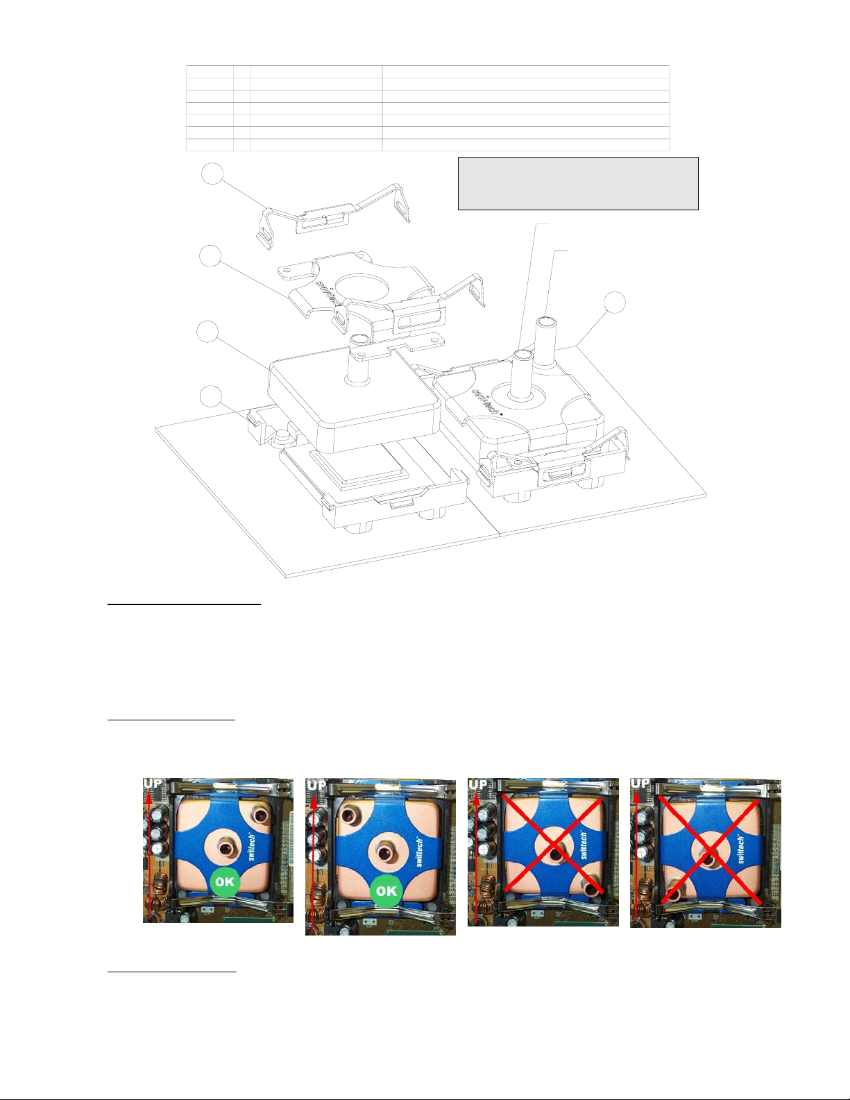
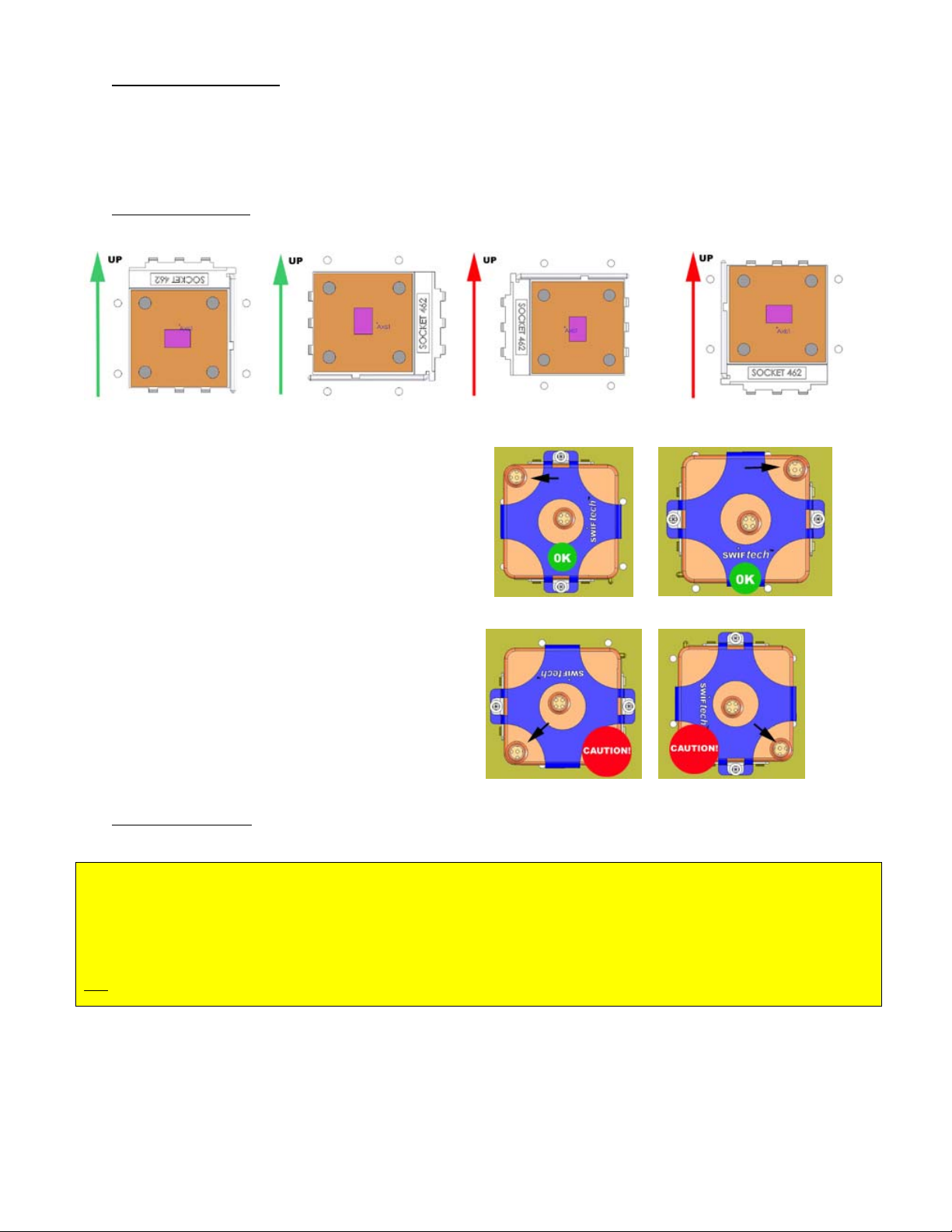
9. Water-block orientation
There are 4 possible socket orientations in socket A (socket 462) motherboards:
Case 1
Most common - OK
In order to bleed correctly during the fill and bleed operations, and
while the system is standing upright, the water-block discharge should
always be at the highest point, as shown in case 1 and 2.
If your block installs as shown in case 1 and 2, then proceed with
installation instructions in paragraph 3.
If due to the socket orientation the water-block is oriented as shown in
case 3 or 4, such as frequently encountered in dual processor boards
for example, then the water-block must be bled PRIOR to installation
onto the socket:
Simply set-up your cooling circuit first, and while filling it up with fluid,
hold the water-block in your hand with the discharge pointing upwards
so that all the air trapped into the block will escape.
water-block onto the socket.
10. Water-block installation
Case 2
Most common - OK
Then attach the
Case 3
Dual processor boards Caution!
Case 1
Case 3
Case 4
Dual processor boards Caution!
Case 2
Case 4
CRITICAL PREAMBLE - MUST READ!
As shown in figure 1 page 1, there is a specific side allocated to each spring: the STIFF spring goes opposite to the socket cam-box, and the
SOFT spring goes on the same side as the socket cam-box. The springs are color-coded to prevent any mistakes: the stiff spring has been
plated with a black zinc coating, while the soft spring is zinc plated in a shiny metallic grey.
You MUST be extremely careful to respect this arrangement!
Not respecting this arrangement will result in unbalanced pressure, and prevent the water-block from sitting flat on the processor,
resulting in high temperatures, and likely damage to the CPU.
Rouchon Industries, Inc., dbA Swiftech™ – 1703 E. 28th St, signal Hill, CA 90755, USA – T (562) 595-8009 – F (562) 595-8769 – All content
Copyright Swiftech 2004 – Last edited 9-27-04 – Subject to revision without notice - 31 of 40 -
Page 32

Place the MCW6000-A over the CPU as shown in figure 1 page 1.
The water-block step side MUST be located over the socket cam box. A label affixed
to the base of the water-block clearly identifies which side this is.
The retention clips should snap over each side, and hook onto the socket tabs.
Make sure that the clips are properly aligned to fit snugly underneath the tabs.
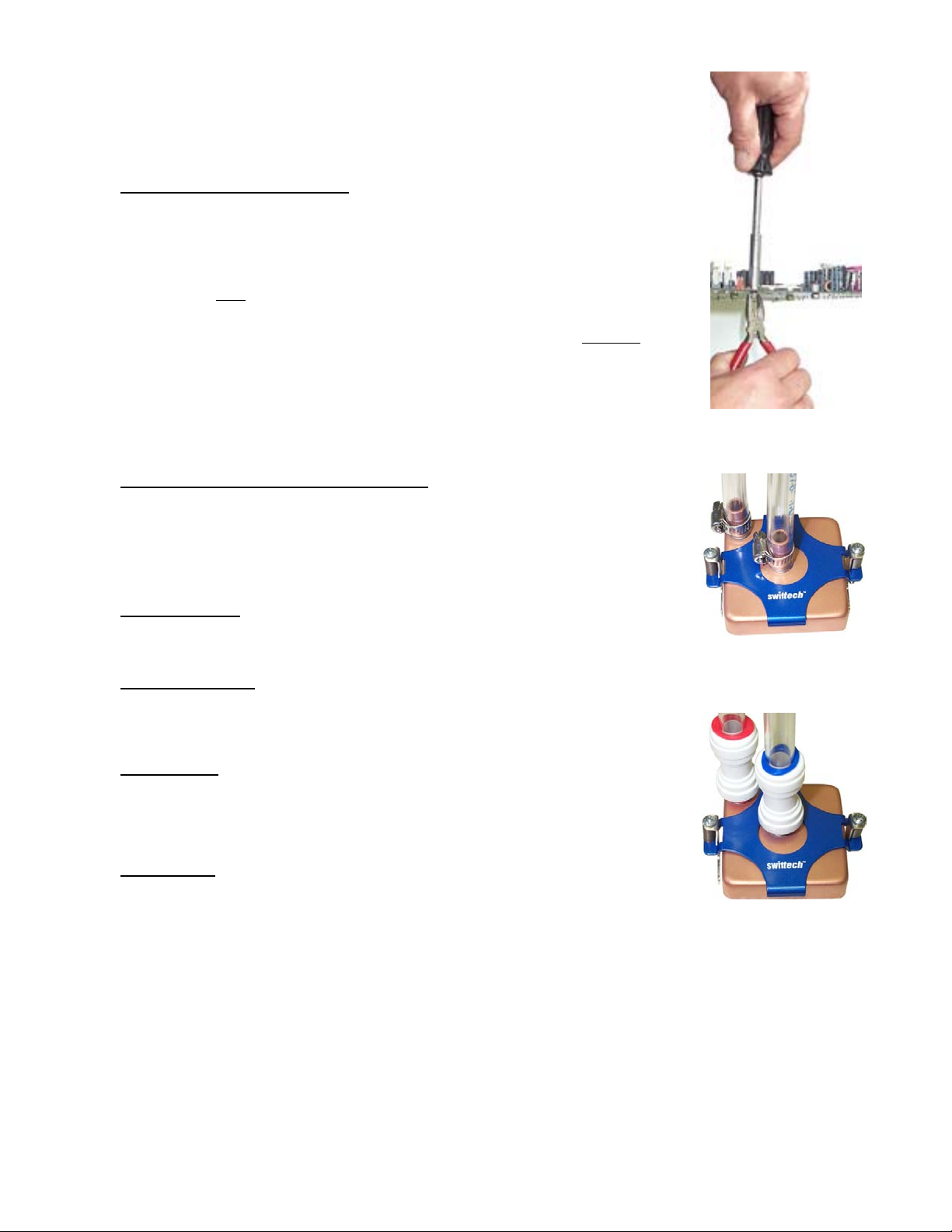
Gradually loosen (counter-clockwise) each spring-loaded screw to release the
spring tension, checking that the clips remain engaged underneath the tabs.
TIP: if space permits, hold the clips pressed against the socket while loosening
the screws, as shown in figure 2. This will prevent the clips for disengaging
themselves from underneath the tabs at start-up.
Figure 2
Continue backing off until the head of the screw completely clears the top of
the bracket, as shown figure 3.
Double-check to ensure that the clips have remained underneath the tabs.
Installation on the CPU is now complete!
Figure 3
11. Connecting the water-block(s) to the cooling circuit:
Carefully identify the direction of the flow in your circuit. For the MCW6000 to operate
properly, the fitting located at the center of the water-block
.
INLET
TIP! In multi-processor environments, connect the two blocks in series: For
example: pump discharge to inlet of processor 1, discharge of processor 1 to inlet of
processor 2, and discharge of processor 2 to radiator.
Attaching the tubes:
The MCW6000™ ships with 2’ of tube already clamped to inlet and outlet.
Alternate connections:
The MCW6000™ can also be used with optional quick-connect fittings (fig.5), or regular
worm-drive hose clamps (fig. 4).
12. Type of Coolant:
Being entirely made of copper, the MCW6000™ may be used with pure water, and does not
necessitate the use of anti-corrosion agents. The use of an algaecide is nonetheless
recommended in any liquid cooling system, and our HydrX™ additive also performs such
function.
13. Final inspection:
Once the installation is completed, it is always a good idea to test the circuit for leaks, prior to
powering up the computer. Do not test the water-block using city water pressure. This
will bow the top of the housing and render the block unusable (and will void your warranty).
Maximum pressure allowable for testing is 25 psi (1.7 bar)
Troubleshooting help is available on our web site at www.swiftnets.com
customer support at 562-595-12009.
Rouchon Industries, Inc., dbA Swiftech™ – 1703 E. 28th St, signal Hill, CA 90755, USA – T (562) 595-8009 – F (562) 595-8769 – All content
Copyright Swiftech 2004 – Last edited 9-27-04 – Subject to revision without notice - 32 of 40 -
MUST BE USED AS THE
, or by calling
Tubes attached with worm-drive
clamps
Optional quick-connect fittings
Page 33

Installation guide for AMD K8 processors
Parts QTY PARTS QTY
MCW6000™ water-block 1 Spring loaded screw assemblies 2
This product is intended for expert users. Please consult with a qualified technician for installation. Improper installation may result in damage to your
components. Swiftech assumes no liability whatsoever, expressed or implied, for the use of these products, nor their installation. The following
instructions are subject to change without notice. Please visit our web site at www.swiftnets.com
Worm drive clamps 2 Sk8 hold-down plate 1
for updates.
4
5
6
7
8
2
ITEM NO. QTY. PART NO. DESCRIPTION
1 1 MCW6000-R2 MCW6000 flat base water-block
2 1 S754-RETENTION-r2 SK8 hold-down plate for AMD K8
3 1 K8_Motherboard AMD K8 (Athlon 64 & Opteron) motherboard+processor assy.
1 counter-plate
1 motherboard
1 retention-frame
4 2 91772A158-6-32X1.75 6-32 x 1 3/4" philips screw
5 2 93286A041-WASHER zinc plated washer
62885 spring
7 2 spacer-205x140x773 tension limiter
8 2 6-32 nylon retaining washer 6-32 nylon retaining washer
1. Preparing your motherboard
1
3
3
Figure 13
a. Remove the existing heat sink
Carefully clean the CPU.
b.
c. Lightly coat the CPU with thermal compound. We recommend high quality thermal compound such as Arctic Silver or
equivalent. Application will vary depending on the type of processor. We recommend visiting www.arcticsilver.com for
detailed instructions.
Rouchon Industries, Inc., dbA Swiftech™ – 1703 E. 28th St, signal Hill, CA 90755, USA – T (562) 595-8009 – F (562) 595-8769 – All content Copyright
Swiftech 2004 – Last edited 9-27-04 – Subject to revision without notice - 33 of 40 -
Page 34

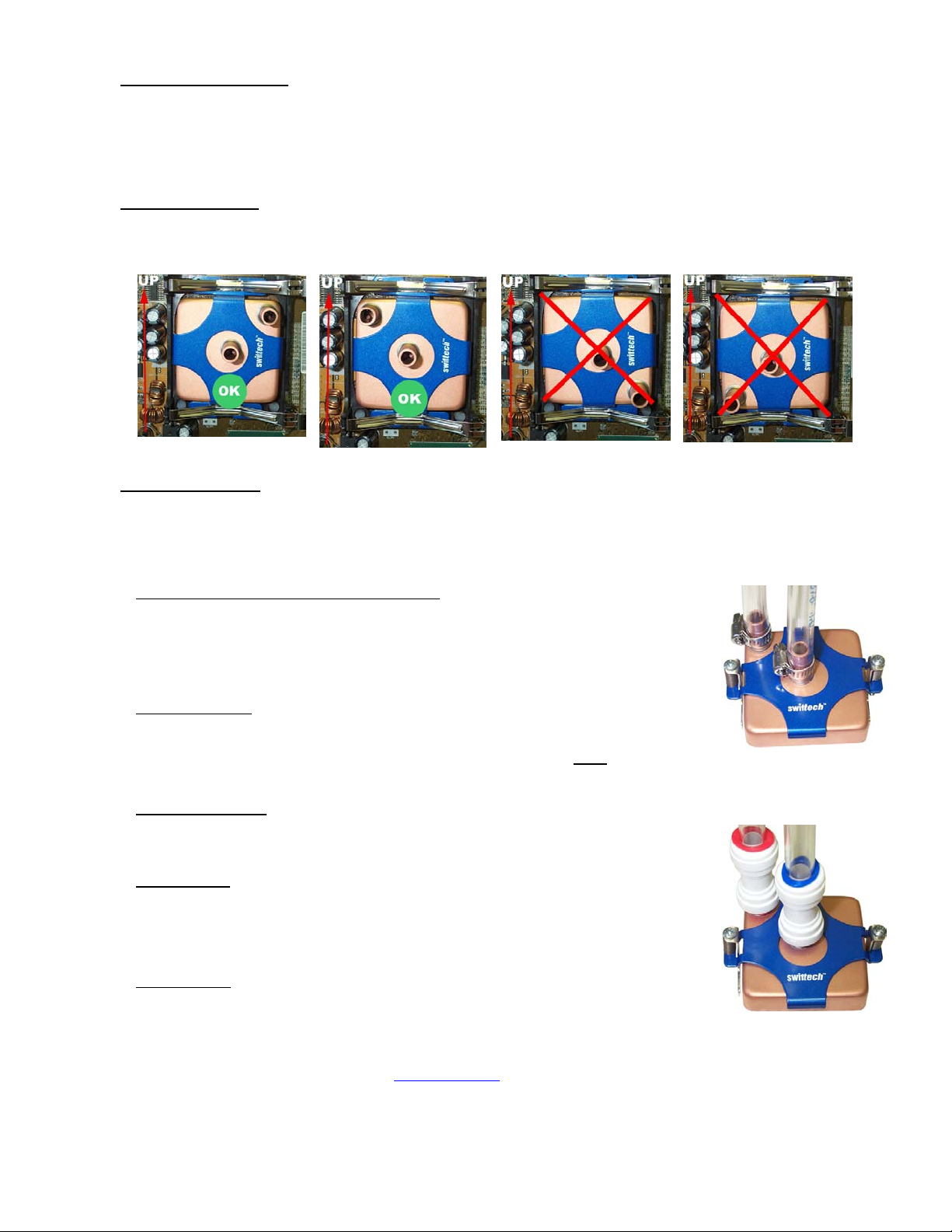
2. Water-block orientation
For ease of operations during bleeding, the outlet should always be at the highest point (while system is standing upright)
3. Water-block installation:
The MCW6000™ simply bolts onto AMD retention frame as shown in figure 1, using the enclosed spring-loaded screws. The tension limiter is
designed to provide appropriate tension to the springs. Do not over-tighten the springs.
4. Retention frame issues:
Most K8 compatible motherboards are shipped with AMD’s validated plastic retention frame and
metallic back-plate. In an effort to spare unnecessary costs to the majority of users, Swiftech does not
include these items with the MCW6000 water-block.
Some motherboards however use non-standard retention systems, and plastic back-plates instead of
the recommended metallic plates described in AMD’s Athlon™ 64 Processor Thermal Design Guide.
For this reason, Swiftech offers an optional retention frame and back plate made to AMD
standards, under Part # AJ00172 shown to the right.
5. Connecting the water-block(s) to the cooling circuit:
Carefully identify the direction of the flow in your circuit. For the MCW6000 to operate properly, the
fitting located at the center of the water-block
6. Attaching the tubes:
The MCW6000™ ships with 2’ of tube already clamped to inlet and outlet.
MUST BE USED AS THE INLET.
7. Alternate connections:
The MCW6000™ can also be used with optional quick-connect fittings (fig.5), or regular worm-drive
hose clamps (fig. 4).
8. Type of Coolant:
Being entirely made of copper, the MCW6000™ may be used with pure water, and does not
necessitate the use of anti-corrosion agents. The use of an algaecide is nonetheless recommended in
any liquid cooling system, and our HydrX™ additive also performs such function.
9. Final inspection:
Once the installation is completed, it is always a good idea to test the circuit for leaks, prior to powering
up the computer.
housing and render the block unusable (and will void your warranty). Maximum pressure allowable
for testing is 25 psi (1.7 bar)
Troubleshooting help is available on our web site at www.swiftnets.com
at 562-595-12009.
Rouchon Industries, Inc., dbA Swiftech™ – 1703 E. 28th St, signal Hill, CA 90755, USA – T (562) 595-8009 – F (562) 595-8769 – All content Copyright
Swiftech 2004 – Last edited 9-27-04 – Subject to revision without notice - 34 of 40 -
Do not test the water-block using city water pressure. This will bow the top of the
, or by calling customer support
Tubes attached with worm-drive
clamps
Optional quick-connect fittings
Page 35

A
Parts QTY PARTS QTY
MCW50™ assembly 1 Spring 6
2-56 S/S socket screw 4 Nylon retaining washer 2
4-40 x 1” S/S phillips screw 2 Tube insert 4
Nylon screw spacer 6 Thermal compound 1
Nylon washer 4 Socket wrench 1
This product is intended for expert users only. Please consult with a qualified technician for installation. Improper installation may result in
damage to your components. Swiftech assumes no liability whatsoever, expressed or implied, for the use of these products, nor their
installation. The following instructions are subject to change without notice. Please visit our web site at www.swiftnets.com
Installation diagram
for updates.
MCW50 for
Nvidia Gforce
MCW50 for
TI Radeon
PRE-ASSEMBLED
Nylon washer
Spring
Nylon screw
spacer
2-56 S/S socket
Figure 1
1. Preparing your graphics card
Before installing the block onto the graphics card cut two pieces of tubing of sufficient length to connect to the rest of your circuit, and install them
into the MCW50™ Inlet and outlet. It is
d. Remove the existing heat sink
e. Carefully clean the GPU (graphics processing unit)
f. Lightly coat the GPU with the provided thermal compound.
preferably a razor blade, or a credit card, held between thumb and index at a 45-degree angle.
absolutely imperative to use the provided tube inserts with clear vinyl (soft) tubing, as shown below:
screw
Shown here with an MCW50-T™ version
Figure 2
Only a paper-thin coat is necessary. It should be applied using
Shown here with an MCW50-T™ version
Nylon retaining
washer
Spring
Nylon screw
spacer
4-40 x 1“
philips screw
Make sure that the tubes are fully inserted into the fitting. The tip of the plastic tube
inserts should be flush with the inlet and outlet openings, as shown above. Inserting the
tubes requires a firm push, accompanied by a twisting motion, and a little bit of grease
around the tubing really helps ☺
2. Installing the MCW50™ GPU Cooler
Rouchon Industries, Inc., dbA Swiftech™ – 1703 E. 28th St, signal Hill, CA 90755, USA – T (562) 595-8009 – F (562) 595-8769 – All content Copyright
Swiftech 2004 – Last edited 9-27-04 – Subject to revision without notice - 35 of 40 -
Page 36

The MCW50™ retention mechanism can either use the two diagonal holes featured in many graphics cards such as ATI
Radeon™ 9000 to 9700 families, or the four mounting holes found in NVidia
installed with other graphics processors by using permanent bonding agents, such as thermally conductive epoxies. We
recommend Arctic Silver™ or Arctic Alumina™ epoxy.
Install your block onto the graphics card, as shown in Figure 1 or Figure 2 (p.1) according to your application. A “finger –tight”
lock is sufficient when tightening the spring retention assemblies. Over-tightening will squish the nylon screw spacer body, and
result in uneven pressure over the GPU.
Recommended integration of the MCW50™ in an existing liquid cooling circuit:
Radiator
Outlet
CPU
Inlet
Outlet
GForce™ families of products. It can also be
MCW50
Inlet
Re-install the graphics card in the AGP slot, and proceed with filling and bleeding the cooling circuit.
3. Type of Coolant:
a. For best performance, use 95% distilled water, and 5% Swiftech brand “HydrX” corrosion inhibitor (available here:
http://www.swiftnets.com/store/category.asp?CatID=2
b. In ALL cases, you MUST use Distilled water AND a corrosion inhibitor with the MCW50 water-block. Regular automotive
anti-freeze is acceptable. Automotive manufacturers recommend that not less than 25% is used.
c. NEVER use tap water, even for a short-term test.
d. Not following paragraphs b and c above constitutes misuse (*) of the product, and will void your warranty.
4. Final inspection
Once the installation is completed, it is always a good idea to test the circuit for leaks, prior to powering up the computer. Troubleshooting help
is available on our web site at www.swiftnets.com
Outlet
Inlet
, or by calling customer support at 562-595-12009.
Pump
Outlet
Inlet
, under the “accessories” section).
Final note concerning removal of the tubing: Push in collet squarely against face of fitting. With the collet held in this
position, the tube can be safely pulled out. Do not attempt to pull the tube out without pushing squarely against the collet. This may result in damaging
the fitting. Further details for using quick-connect fittings are also available here: http://www.johnguest.com/install_6.shtm#disconnect
:
Rouchon Industries, Inc., dbA Swiftech™ – 1703 E. 28th St, signal Hill, CA 90755, USA – T (562) 595-8009 – F (562) 595-8769 – All content Copyright
Swiftech 2004 – Last edited 9-27-04 – Subject to revision without notice - 36 of 40 -
Page 37

Installation guide for Intel & AMD platforms
Common parts to both platforms Intel platform specific parts AMD platforms specific parts
Part Qty Part Qty Part Qty
MCW20 ™ assembly 1 Neoprene pads (strip of 4) 1 4-40 x 1 1/2” Philips screws 2
Tube inserts 2 4-40 HOOKS 2 Black fiber washers 6
Arctic Alumina Thermal
compound
4-40 x 3/16” socket screw 0.8120” Spring 2 0.300” Spring 2
Socket wrench tool 2 Long bracket (1.10”) 2 ¼” tension limiters 2
1 Acorn nuts 2 Short bracket (.71”) 2
Knurled knobs 2
This product is intended for expert users. Please consult with a qualified technician for installation. Improper installation may result in
damage to your components. Swiftech assumes no liability whatsoever, expressed or implied, for the use of these products, nor their
installation. The following instructions are subject to change without notice. Please visit our web site at www.swiftnets.com
1. Preparation steps common to both platforms
1 Nylon tension limiter ½” 2 4-40 mini-nuts 2
for updates.
Step 1: Pre-installation assembly schematics
attach the brackets to the water-block with the provided socket wrench tool.
Step 2: Prepare the tubing
a. Prepare two pieces of tubing of sufficient length to connect to the
rest of your circuit. The cuts must be square as shown in figure 1 or
leaks may occur:
Intel
Platforms AMD platforms
Figure 14
Figure 15
b. Install the provided plastic tube inserts at each end of
the tubes, as shown in figure 4: these inserts are absolutely
imperative when using any kind of soft tubing, such as vinyl,
ClearFlex, Tygon, etc.
Rouchon Industries, Inc., dbA Swiftech™ – 1703 E. 28th St, signal Hill, CA 90755, USA – T (562) 595-8009 – F (562) 595-8769 – All content Copyright
Swiftech 2004 – Last edited 9-27-04 – Subject to revision without notice - 37 of 40 -
Page 38

Square cut
Figure 16
c. Spread a little bit of grease or liquid
around the tubing. It helps pushing the
soap
tubes in, particularly with Clearflex
which features a very “sticky” surface.
Figure 18
2. Installation for Intel platforms
a. Prepare your Motherboard
Remove the existing heat sink
Carefully clean the processor, using alcohol
Install the 4 neoprene pads as shown figure 8. This
step is only necessary if the processor core is
exposed.
large lid covering the entire area of the chipset),
then the neoprene pads MUST not be installed.
Lightly coat the processor with the provided thermal
compound. Only a paper-thin coat is necessary. It
should be applied using preferably a razor blade, or a
credit card, held between thumb and index at a 45
angle
If the chipset features a heat spreader (a
tubing,
Figure 17
Figure 19
d. Fully insert both tubes into the fittings. The tip of the plastic tube inserts should
be flush with the inlet and outlet openings, as shown in figure 4 above. Inserting the
tubes requires a firm push, accompanied by a twisting motion.
°
Figure 20
Figure 21
Rouchon Industries, Inc., dbA Swiftech™ – 1703 E. 28th St, signal Hill, CA 90755, USA – T (562) 595-8009 – F (562) 595-8769 – All content Copyright
Swiftech 2004 – Last edited 9-27-04 – Subject to revision without notice - 38 of 40 -
Page 39
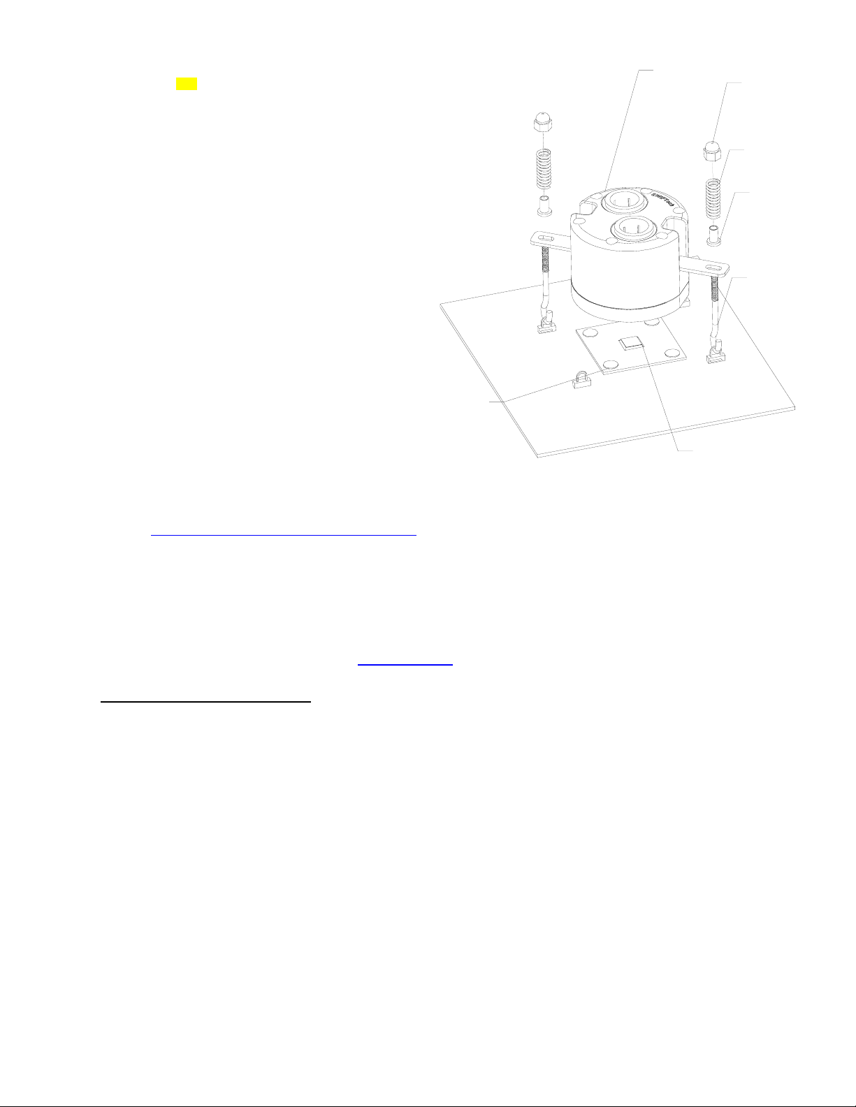
A
Install the MCW20-P™ water-block
b.
TIP! It is preferable to have the tubing inserted
into the water-block BEFORE you install the
block onto the motherboard. This is because
pushing the tubes into the block while it is
already installed could exert undue pressure
onto the microprocessor.
Place the MCW20-P™ onto the processor, as
shown in figure 9: hooks should be engaged into
two diagonal motherboard loops first, then install
the nylon tension limiters (flange facing down),
the springs, and tighten the assembly with the
acorn nuts.
Neoprene
pad
MCW20-P
corn nut
Spring
Nylon spacer
Hook
Chipset core
c. Connect the block to the rest of the cooling circuit.
d. Type of Coolant:
e.
a. For best performance, use 95% distilled water, and 5% Swiftech brand “HydrX” corrosion inhibitor (available here:
http://www.swiftnets.com/store/category.asp?CatID=2
b. In ALL cases, you MUST use Distilled water AND a corrosion inhibitor with the MCW5002 water-block. Regular automotive anti-freeze
is acceptable. Automotive manufacturers recommend that not less than 25% is used.
c. NEVER use tap water, even for a short-term test.
d. Not following paragraphs b and c above constitutes misuse (*) of the product, and will void your warranty.
Final inspection
Once the installation is completed, it is always a good idea to test the circuit for leaks, prior to powering up the computer. If using
Swiftech’s fill-and-bleed kit, such test can be done without any liquid into the circuit. Please refer to the FBK525
Troubleshooting help is available on our web site at www.swiftnets.com
, under the “accessories” section).
, or by calling customer support at 562-595-12009.
Figure 22
installation guide for details.
3. Installation for AMD platforms
1. Preparing your Motherboard
Remove the motherboard from the chassis
Remove the existing heat sink
Carefully clean the microprocessor, using alcohol
Rouchon Industries, Inc., dbA Swiftech™ – 1703 E. 28th St, signal Hill, CA 90755, USA – T (562) 595-8009 – F (562) 595-8769 – All content Copyright
Swiftech 2004 – Last edited 9-27-04 – Subject to revision without notice - 39 of 40 -
Page 40

2. Installing MCW20-A™ water-block
Install the provided screws through the
motherboard, using a black fiber washer on both sides of
the motherboard, and tighten the nuts.
Install the motherboard back into the chassis
Lightly coat the microprocessor with the provided
thermal compound. Only a paper-thin coat is necessary.
It should be applied using preferably a razor blade, or a
credit card, held between thumb and index at a 45-
degree angle.
TIP! It is preferable to have the tubing inserted into
the water-block BEFORE you install the block onto the
motherboard. This is because pushing the tubes into the
block while it is already installed could exert undue
pressure onto the microprocessor.
Slide down the MCW20-A over the retention
screws, as shown figure 10, then install the nylon tension
limiters (flange facing down), the springs, and tighten the
assembly with the knurled knobs. Over tightening of the
assembly is prevented by the tension limiter. Users
should be cautious nonetheless, as nylon can be easily
crushed.
4-40 x 1 1/2“ philips screw
Figure 23
3. Connect the block to the rest of the cooling circuit.
The block is designed in such a way that it will bleed itself automatically in any vertical orientation (computer standing-up).
4. Type of Coolant:
5.
Note concerning removal of the tubing in quick-connect fittings: Push in
the collet squarely against the face of the fitting using Swiftech’s tube removal
tool, or a wrench of approximately the same opening diameter as the tube (1/2”
+). The collet is the inner plastic ring protruding from the face of fitting. It fits
loosely into the fitting, and can be moved up and down by approximately 1/8”.
With the collet firmly held against the face of the fitting, the tube can be safely
pulled out. Do not attempt to pull the tube out without pushing squarely against
the collet. This may result in damaging the fitting.
i) For best performance, use 95% distilled water, and 5% Swiftech brand “HydrX” corrosion inhibitor (available here:
http://www.swiftnets.com/store/category.asp?CatID=2
ii) In ALL cases, you MUST use Distilled water AND a corrosion inhibitor with the MCW5002 water-block. Regular automotive anti-freeze
is acceptable. Automotive manufacturers recommend that not less than 25% is used.
iii) NEVER use tap water, even for a short-term test.
iv) Not following paragraphs b and c above constitutes misuse (*) of the product, and will void your warranty.
Final inspection
Once the installation is completed, it is always a good idea to test the circuit for leaks, prior to powering up the computer. Troubleshooting
help is available on our web site at www.swiftnets.com
, or by calling customer support at 562-595-12009.
, under the “accessories” section).
Figure 24
Rouchon Industries, Inc., dbA Swiftech™ – 1703 E. 28th St, signal Hill, CA 90755, USA – T (562) 595-8009 – F (562) 595-8769 – All content Copyright
Swiftech 2004 – Last edited 9-27-04 – Subject to revision without notice - 40 of 40 -
Figure 25
 Loading...