

Page 1

These instructions are updated on a regular basis. Please visit our web site at
http://www.swiftnets.com
Copyright Swiftech 2005 – All rights reserved – Last revision date: 09-22-06 - Information subject to change without notice – URL: http://www.swiftnets.com
Rouchon Industries, Inc., dba Swiftech – 1703 E. 28
th
Street, Signal Hill, CA 90755 – Tel. 562-595-8009 – Fax 562-595-8769 - E Mail: Swiftech@swiftnets.com PAGE 1 of 26
Page 2
Packing List
QTY ITEM
1 APOGEE water-block, including hold-down plates (multi sockets
and AM2), various processors mounting systems, and (2) hose
clamps
1 MCRES-1000P pump & reservoir 5 ¼” bay assembly, including
mounting hardware and (2) ½” hose clamps
1 MCR120 Radiator assembly, including pre-installed 120mm fan
without fan guards, mounting hardware, (1) 12v to 7v adapters,
(1) 12v to 5v 3-pin to 4-pin Molex adapters, (2) hose clamps, and
MCB-120 Radbox, with mounting hardware
8 Feet 3/8” (tube ID) industrial grade PVC tubing
1 Length (40”) Smartcoils 500 clear
1 2 Oz. Bottle of HydrX concentrated coolant
1 Syringe of Arctic Céramique thermal compound
Processor & Motherboard Compatibility
Intel®
Pentium® 4, D, Celeron
Socket 478
Socket 775
Xeon™ (socket 603 and 604)
400 & 533 MHz FSB
800 MHz FSB (Nocona) – See Note 1
AMD®
Athlon XP, MP, Duron, Sempron, socket 462 (see Note 2)
Athlon 64, Sempron, Socket 754
Opteron, socket 939, 940
Note 1 to dual “Nocona” processor users: since the H20-120 Premium is provided with one Waterblock only, you will need to procure another Apogee
Waterblock separately for your second. Please note that the “Nocona” hardware is not included with the Apogee Waterblock and also needs to be
procured separately under part number: AP-NC604
Note 2: This product is exclusively compatible with socket A (socket 462) motherboards featuring (4) mounting holes around the socket.
Copyright Swiftech 2005 – All rights reserved – Last revision date: 09-22-06 - Information subject to change without notice – URL: http://www.swiftnets.com
Rouchon Industries, Inc., dba Swiftech – 1703 E. 28
th
Street, Signal Hill, CA 90755 – Tel. 562-595-8009 – Fax 562-595-8769 - E Mail: Swiftech@swiftnets.com PAGE 2 of 26
Page 3

TABLE OF CONTENT
I.
TUBE ROUTING.............................................................................................................................................................5
II. INSTALLATION OF THE COOLING COMPONENTS...................................................................................................5
1 MCR120-F RADIATOR INSTALLATION ..............................................................................................................................................................................6
Internal radiator installation.......................................................................................................................................................................................6
Back of the case radiator installation:................................................................................................................................................................6
Front of the case Radiator installation:..............................................................................................................................................................6
External radiator installation using the “Radbox”...............................................................................................................................................7
2 APOGEE WATER-BLOCK INSTALLATION .........................................................................................................................................................................10
Common installation guidelines..............................................................................................................................................................................11
Step-by step summary............................................................................................................................................................................................11
Individual installation schematics............................................................................................................................................................................11
Intel® Pentium® 4 Socket 478................................................................................................................................................................................12
Intel® Pentium® 4 and Pentium® D Socket LGA 775............................................................................................................................................13
Intel® Xeon™ Socket 604 “Nocona” 800 MHz FSB motherboards........................................................................................................................14
Intel® Xeon™ Socket 603/604400 and 533 MHz FSB motherboards....................................................................................................................15
AMD® Athlon®, Duron®, MP, XP, Sempron® Socket 462 ....................................................................................................................................16
AMD® 64, Sempron®, Opteron® Socket 754, 939, 940........................................................................................................................................17
AMD® 64, FX, X2, Sempron®, Socket AM2...........................................................................................................................................................18
3
PREPARING THE TUBING................................................................................................................................................................................................20
4 MCRES-1000P ASSEMBLY INSTALLATION.....................................................................................................................................................................21
Preparing the HydrX coolant...................................................................................................................................................................................21
A. First time installation and preferred filling procedure..........................................................................................................................................21
B. Alternate filling procedure...................................................................................................................................................................................23
5 NOTES AND TROUBLESHOOTING ....................................................................................................................................................................................24
6 MCP350™ PUMP SPECIFICATIONS ................................................................................................................................................................................24
7 COMPLETING THE INSTALLATION....................................................................................................................................................................................25
III. DRAINING THE SYSTEM............................................................................................................................................25
IV. PERIODIC MAINTENANCE.............................................. .... ... ........ .... ... .... .... .... ... .... ........ .... ... .... ............................25
V. ADD-ON COMPONENTS.............................................................................................................................................26
Copyright Swiftech 2005 – All rights reserved – Last revision date: 09-22-06 - Information subject to change without notice – URL: http://www.swiftnets.com
Rouchon Industries, Inc., dba Swiftech – 1703 E. 28
th
Street, Signal Hill, CA 90755 – Tel. 562-595-8009 – Fax 562-595-8769 - E Mail: Swiftech@swiftnets.com PAGE 3 of 26
Page 4

INTRODUCTION
Congratulations on your purchase of a Swiftech™ H20-120 PREMIUM Liquid Cooling System!
This kit has been designed to facilitate the installation of the components without having to make any modifications to the
chassis. While all attempts have been made to make the installation of this system user friendly, please note that this
system is intended for users that are well versed in installing computer components.
G
ENERAL GUIDELINES
Please read this guide carefully and entirely before you start this installation. Plan your installation ahead. Observe the
relative position of the components for possible interference with other components.
Never work with electricity connected to the computer while work is in progress.
While it is possible to install the kit in a chassis already populated with all typical components, such as hard
drive, CD Rom, power supply, Video Card, etc, it is recommended that these components be removed from
the case prior to installing the water cooling system. The motherboard and CPU may remain in the chassis ,
and will be useful to estimate the length of tubing necessary to connect the different components. But the
motherboard must be disconnected from the power-supply during the entire mock-up phase of the installation.
In case of a spill or leak on the motherboard, do not panic! As long as the motherboard is not electrically
connected, no harm is done. You must however thoroughly dry the exposed area, using a hair dryer for
example, and wait a minimum of 6 to 8 hours prior to re-connecting the motherboard to its power source.
The reservoir should preferably be at the highest point of the cooling circuit (top 5 ¼” tray).
Think about the airflow inside your chassis. In liquid-cooling environments, it is always better to draw fresh air
from the outside through the radiator, as opposed to using the warm air from inside the computer.
Make sure to dry-fit all components before making final connections and filling the water-cooling system.
DISCLAIMER
While all efforts have been made to provide the most comprehensive tutorial possible , Swiftech assumes no liability
expressed or implied for any damage(s) occurring to your components as a result of using Swiftech cooling products,
either due to mistake or omission on our part in the above instructions, or due to failure or defect in the Swiftech™
cooling products.
In addition, Swiftech assumes no liability, expressed or implied, for the use of this product, and more specifically for
any, and all damages caused by the use of this product to a ny other device in a personal computer, whether due to
product failure, leak, electrical short, and or electro-magnetic emissions.
WARRANTY
Our products are guaranteed for 12 months from the date of delivery to the final user against defects in materials or
workmanship. During this period, they will be repaired or have parts replaced provided that: (I) the product is returned to
the agent from which it was purchased; (II) the product has been purchased by the end user and not used fo r hire
purposes; (III) the product has not been misused, handled carelessly, or other than in accordance with any instructions
provided with respect to its use. This guarantee does not confer rights other than those expressly set out above and
does not cover any claims for consequential loss or damage. This guarantee is offered as an extra benefit and does not
affect your statutory rights as a consumer.
Copyright Swiftech 2005 – All rights reserved – Last revision date: 09-22-06 - Information subject to change without notice – URL: http://www.swiftnets.com
Rouchon Industries, Inc., dba Swiftech – 1703 E. 28
th
Street, Signal Hill, CA 90755 – Tel. 562-595-8009 – Fax 562-595-8769 - E Mail: Swiftech@swiftnets.com PAGE 4 of 26
Page 5

I. TUBE ROUTING
The tubing for the water-cooling system must be routed to form a complete loop that includes all elements of the system. When daisy-chaining
components, the simplest and most natural route is usually the best. Always avoid sharp bends that would kink the tubing!
The following table contains examples on how to establish connections between the different elements of a cooling circuit based on multiple
possible configurations. These are guidelines only, and may change depending on the relative position of the components inside your chassis.
From a performance standpoint there is very little performance to be gained from strictly controlling the component sequence: the maximum delta T
(difference in temperature) between any two points of the liquid cooling circuit does not exceed 1ºC. Whenever possible, performance oriented
users will typically want to route the radiator discharge(s) tube(s) to the inlet of the CPU cooler, since the fluid exiting the radiators is always the
coolest.
Devices: (1) CPU cooler + (1) Radiator + Pump-reservoir assembly
Connect: Pump discharge to radiator inlet
Radiator discharge to CPU cooler inlet
CPU cooler discharge to reservoir inlet
Alternatively,
Connect Pump discharge to CPU cooler inlet
CPU cooler discharge to radiator inlet
Radiator discharge to reservoir inlet
Devices (1) CPU cooler + (1) VGA cooler + (1) Radiator + Pump-reservoir assembly
Connect: Pump discharge to VGA Cooler inlet
VGA cooler discharge to radiator inlet
Radiator discharge to CPU cooler inlet
CPU cooler discharge to reservoir inlet
Alternatively,
Connect: Pump discharge to CPU cooler inlet
CPU cooler discharge to VGA cooler inlet
VGA cooler discharge to radiator inlet
Radiator discharge to reservoir inlet
Devices: (1) CPU cooler + (1) VGA Cooler + (1) chipset Cooler + (1) Radiator + Pump-reservoir assembly
Connect: Pump discharge to chipset cooler inlet
Chipset cooler discharge to VGA cooler inlet
VGA cooler discharge to radiator inlet
Radiator discharge to CPU cooler inlet
CPU cooler discharge to reservoir inlet
Alternatively,
Connect: Pump discharge to CPU cooler inlet
CPU cooler discharge to chipset cooler inlet
Chipset cooler discharge to VGA cooler inlet
VGA cooler discharge to radiator inlet
Radiator discharge to reservoir inlet
Devices: Dual CPU cooler and VGA cooler (SLI) configurations
Connect: CPU coolers in series: CPU cooler (1) discharge to CPU cooler (2) inlet
VGA coolers in series: VGA cooler (1) discharge to VGA cooler (2) inlet
Devices: Dual Radiators: A second radiator can be added anywhere in the loop in series with the other components,
For example
Connect Pump discharge to radiator (1) inlet
Radiator (1) discharge to VGA cooler inlet
VGA Cooler discharge to chipset cooler inlet
Chipset cooler discharge to radiator (2) inlet
Radiator (2) discharge to CPU cooler inlet
CPU cooler discharge to reservoir inlet
II. Installation of the cooling components
Placement of the cooling components may vary depending on your chassis and motherboard configurations. A mock-up installation is thus necessary to
estimate the length of the different sections of tubing that will be required between each component.
The following is the recommended sequence of components installation.
1. Radiator and fan
2. Water-block(s)
3. Pump and reservoir assembly
Copyright Swiftech 2005 – All rights reserved – Last revision date: 09-22-06 - Information subject to change without notice – URL: http://www.swiftnets.com
Rouchon Industries, Inc., dba Swiftech – 1703 E. 28
th
Street, Signal Hill, CA 90755 – Tel. 562-595-8009 – Fax 562-595-8769 - E Mail: Swiftech@swiftnets.com PAGE 5 of 26
Page 6
1 MCR120-F RADIATOR INSTALLATION
Your first choice is to decide whether you will be installing the radiator
INSIDE of the computer, or use the included “Radbox” to hang the
radiator OUTSIDE at the back of the computer chassis.
There are four considerations that will dictate such choice:
Performance: From a pure performance standpoint, using the Radbox
will always be a superior solution to an installation inside of the
computer because the temperature of the ambient air outside of the
computer –which is used to cool the radiator will always be cooler than
that of the inside even in the best ventilated case. Additional benefits
are also discussed in the Radbox installation section below.
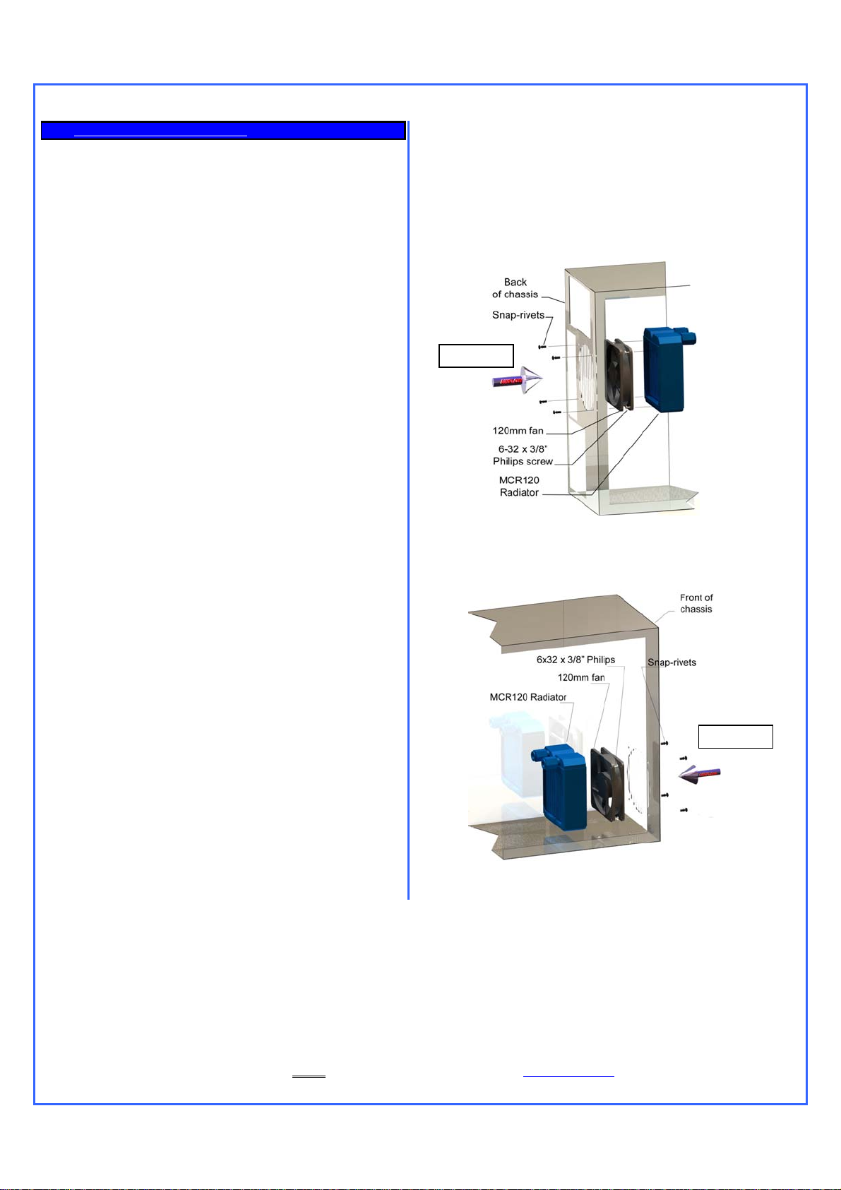
Back of the case radiator installation:
If CPU cooling is a priority, we suggest that the fan be installed in intake
mode in contradiction to the “classic” airflow scheme, which is intake at
the front, and exhaust at the back. In effect, if the fan flow direction were
reversed, it would use heated air from inside of the chassis, which is
usually 3°C (at best) and up to 10°C hotter than that of the ambient air
outside of the chassis. Conversely, users with excellent ventilation in
their case may opt to install the fan in exhaust mode with the
understanding of the above stated temperature handicap.
Space constraints: If your PC has no room inside to install a 120mm
radiator, and if you are not inclined to modify the case to “make it fit”,
the Radbox will allow you to hang the radiator to any standard fan
opening at the back of the chassis, without any modifications; using the
Radbox then also becomes an obvious choice. Conversely, if you have
enough room inside of the PC to install the radiator, BUT your PC is
located in a space constrained area, then adding the Radbox to the
back of the chassis will lengthen the PC, which could prevent its use.
Noise: Having the radiator/fan assembly operating outside of the
chassis may slightly increase the audible noise compared to an internal
installation, because the chassis no longer muffles the noise emitted by
the fan. A mitigating factor to this is the fact that the Radbox assembly is
at the back of the computer, and usually hidden away amidst the
various cables. If the PC is underneath a desk, chances are that there
will be no audible difference between an internal installation and an
external one. However, there are situations where the PC is located in
an open area, close to the user ears. In such case, users in search of
the lowest possible audible noise will prefer to install the radiator inside
of the computer.
Cosmetics: This is the last and probably most difficult choice. Swiftech
cannot presume of the users tastes, and therefore cannot make a
recommendation here.
Swiftech pre-assembles the fan and Radbox components to the
radiator.
Internal radiator installation
AIRFLOW
Figure 1
Front of the case Radiator installation:
This is an ideal location, as the radiator draws fresh air, and the “classic”
airflow scheme is respected.
AIRFLOW
Strictly from a CPU cooling performance standpoint it is always
preferable to install the fan so that it will either draw or push fresh air
from outside of the chassis into the radiator. There are two possible
cases as shown to the right:
Figure 2
Copyright Swiftech 2005 – All rights reserved – Last revision date: 09-22-06 - Information subject to change without notice – URL: http://www.swiftnets.com
Rouchon Industries, Inc., dba Swiftech – 1703 E. 28
th
Street, Signal Hill, CA 90755 – Tel. 562-595-8009 – Fax 562-595-8769 - E Mail: Swiftech@swiftnets.com PAGE 6 of 26
Page 7
External radiator installatio n using the “Radbox”
PCI pass-thru Installation
Make sure to insert your fan electrical connector through the slotted hole of the PCI bracket before you install the tubing. Only 3-pin connectors (the
type that connect to the motherboard) are small enough to pass through the slotted hole. 4-pin Molex connectors (the type that connect to your
power supply) will require that the terminals be removed from the Molex housing first.
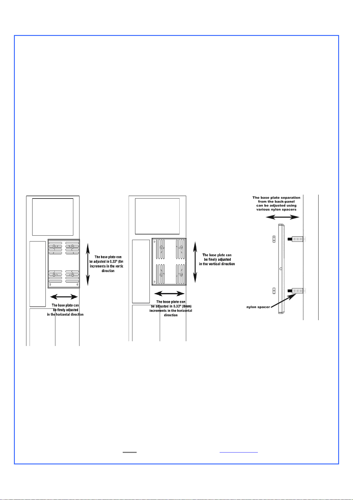
Radbox Installation
Place the radiator assembly on the back of the computer to roughly estimate where it will fit best. You need to consider the following clearance
issues:
1. Exit cables and connectors from various PCI devices: the Radbox base plate can be moved in both vertical and horizontal directions to allow
clearance for the cables.
2. Opening the side panel once the Radbox is installed: the Radbox is supplied with various nylon spacers to separate the base plate from the
surface of the back-panel and to provide clearance for opening of the side-panel (see Fig.3)
Note that a chassis with 80mm fan opening(s) is likely to provide a very good range of adjustments. Conversely, a chassis featuring a single 120mm
fan opening the base-plate is a direct bolt on, but offers no adjustments, which may or may not suit your installation for the purpose of positioning the
radiator. In that case, it will be become necessary to drill (4) mounting holes of 0.150” (~3.5mm) in diameter to install the base plate at the desired
location.
A. Securing the base plate at the desired location:
Copyright Swiftech 2005 – All rights reserved – Last revision date: 09-22-06 - Information subject to change without notice – URL: http://www.swiftnets.com
Rouchon Industries, Inc., dba Swiftech – 1703 E. 28
th
Street, Signal Hill, CA 90755 – Tel. 562-595-8009 – Fax 562-595-8769 - E Mail: Swiftech@swiftnets.com PAGE 7 of 26
Page 8
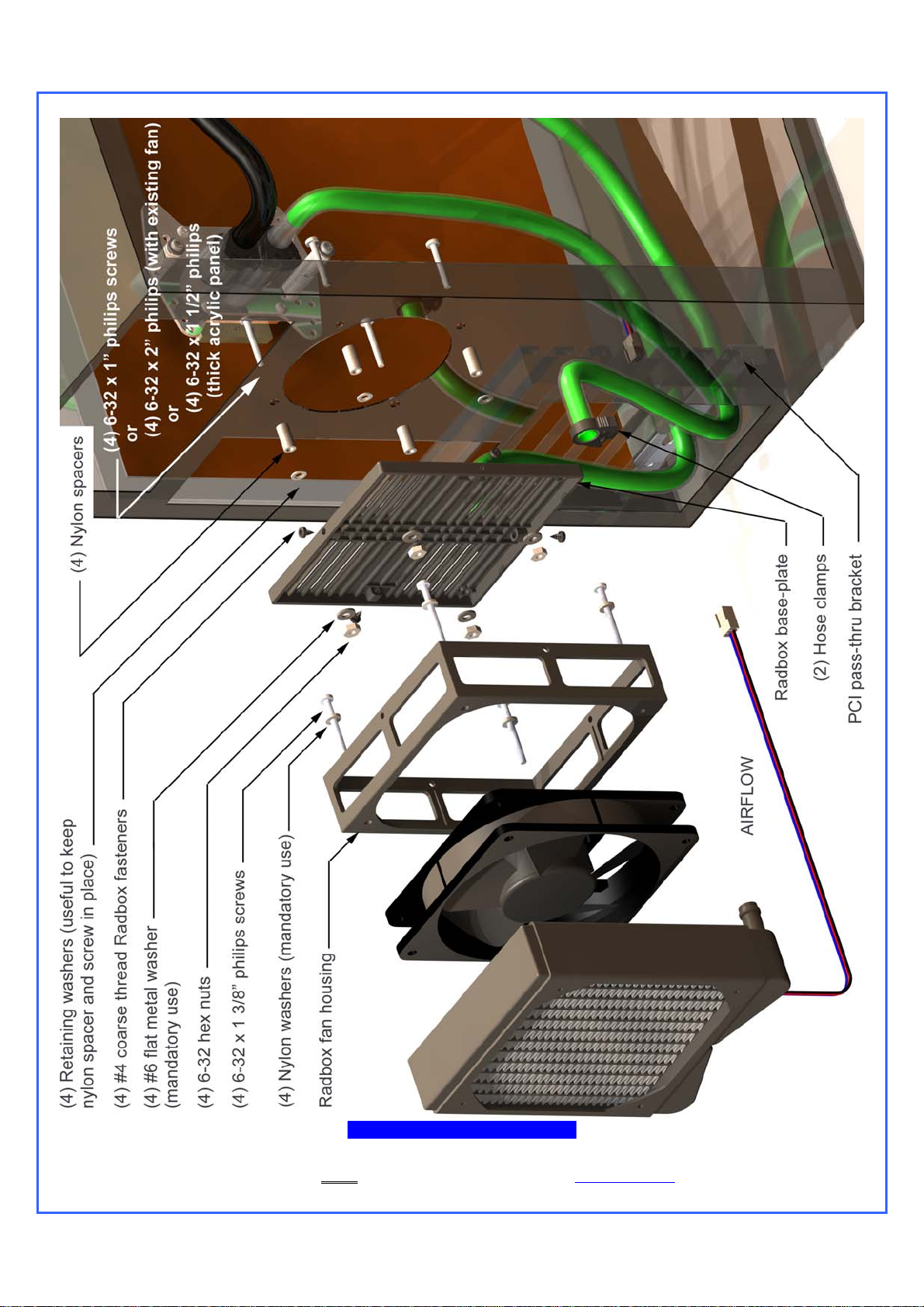
Exploded view of an installation
Copyright Swiftech 2005 – All rights reserved – Last revision date: 09-22-06 - Information subject to change without notice – URL: http://www.swiftnets.com
Rouchon Industries, Inc., dba Swiftech – 1703 E. 28
th
Street, Signal Hill, CA 90755 – Tel. 562-595-8009 – Fax 562-595-8769 - E Mail: Swiftech@swiftnets.com PAGE 8 of 26
Page 9

B. Housing/Fan/Radiator installation
Once you have found a satisfactory position for the Radbox base plate, secure the housing and fan to the radiator using the provided (4) M3.5
x 30mm Philips screws. Ensure that the exit of the fan wire is positioned towards the bottom of the PC and to its left (towards the motherboard)
to facilitate further routing of the wire through the PCI pass-thru.
C. Finalizing the installation
Secure the housing/fan/radiator assembly to the base plate with the provided #4 screws. With the radiator in its final place, you can now cut
two pieces of tubing of sufficient length to connect inlet and outlet of the radiator to the PCI pass-thru nipples. The tubes will form some sharp
bends here, and you must wrap them with the provided Smartcoils by forming tight loops in order to prevent the tubes from kinking. Please
refer to the Smartcoils installation in the chapter 4 for further details on how to use Smartcoils. Once done slip the tubes over their respective
fittings, and secure them with the provided hose clamps.
D. Electrical connection
The fan shipped with the MCR120 uses a 3-pin connector. For 12volt operations, this connector can be safely installed on one of the
motherboard headers. Use any free header other than
the CPU fan header, since the pump RPM sensor will be connected to the CPU fan
header in order to monitor the pump.
For low noise operations, 2 additional fan connector adapters are supplied with the kit, and should be connected to the power supply instead
of a motherboard fan header:
12v to 7v adapter: this setting provides a good balance for performance, at whisper quiet operations
12v to 5v adapter: this setting is for silent operations, and will result in higher processor temperatures.
Please consult the product page (www.swiftnets.com/products/h20-120-premiunm.asp
with respect to CPU temperatures when using the 12 to 7V or 12 to 5V adapters.
Your radiator installation is complete, and we can now move-on to the water-block installation.
) on our web site for specific data
Copyright Swiftech 2005 – All rights reserved – Last revision date: 09-22-06 - Information subject to change without notice – URL: http://www.swiftnets.com
Rouchon Industries, Inc., dba Swiftech – 1703 E. 28
th
Street, Signal Hill, CA 90755 – Tel. 562-595-8009 – Fax 562-595-8769 - E Mail: Swiftech@swiftnets.com PAGE 9 of 26
Page 10

2 APOGEE WATER-BLOCK INSTALLATION
One or more Patents pending
Figure 1 – Exploded View
Copyright Swiftech 2005 – All rights reserved – Last revision date: 09-22-06 - Information subject to change without notice – URL: http://www.swiftnets.com
Rouchon Industries, Inc., dba Swiftech – 1703 E. 28
th
Street, Signal Hill, CA 90755 – Tel. 562-595-8009 – Fax 562-595-8769 - E Mail: Swiftech@swiftnets.com PAGE 10 of 26
Page 11

Packing List
COMPONENT ID COMPONENT DESCRIPTION QTY USAGE
BHSC006C0-007SS 6-32 X 7/16 BUT HD CAP SS 4.00 WATER-BLOCK ASSEMBLY
O-RING 3/32 B1000-133 O-RING 3/32 X 1 13/1 1.00 WATER-BLOCK ASSEMBLY
APOGEE-H APOGEE WATERBLOCK HOUSING 1.00 WATER-BLOCK ASSEMBLY
APOGEE-BRKT APOGEE HOLD-DOWN PLATE 1.00 WATER-BLOCK ASSEMBLY
APOGEE-BP APOGEE BASE PLATE 1.00 WATER-BLOCK ASSEMBLY
B1000-2.5X50 BUNA-N 70D BLACK O-RING 2.00 FITTINGS
PM4S-6BN 1/4" - 1/8 NPSM TO 3/8" ID 2.00 FITTINGS
PM4S-8BN 1/4" - 1/8 NPSM TO 1/2 ID 2.00 FITTINGS
22HC04688 15/32" HOSE CLAMP 2.00 FITTINGS
22HC0672B 43/64" PREMIUM HOSE CLAMP 2.00 FITTINGS
SPRING6 SPRING FOR MCW6000-775 4.00 COMMON HARDWARE
6-32 HEX CAP 6-32 ACRON NUT 4.00 COMMON HARDWARE
12SWS0444 NYLON SHOULDER WASHER 8.00 COMMON HARDWARE
LOCKWASHER6 LOCK WASHER #6 6.00 COMMON HARDWARE
FW140X250X0215FB BLK BLACK FIBER WASHER .140X.250X. 10.00 COMMON HARDWARE
632.112PHPMS 6X32 X 1 1/2 PHILIPS PAN HEAD 4.00 COMMON HARDWARE
6-32 NUT 6-32 NUT 4.00 COMMON HARDWARE
6-32 X 1 5/8 6-32 X 1 5/8 4.00 XEON SCREWS
WASHER-0148X0266X0040-91007A619 LOCK WASHER #6 X 0.040 4.00 AMD SOCKET 754/939/940,AM2 HARDWARE
90272A153-6-32X1.00-PHILIPS SCREW 6-32 X 1” PHILIPS SCREW 4.00 AMD SOCKET 754/939/940, AM2 HARDWARE
13RS040637 ROUND SPACER 4.00 AMD SOCKET 754/939/940,AM2 HARDWARE
APOGEE-AM2-BP APOGEE AM2 BASE PLATE 1.00 AMD SOCKET AM2 HARDWARE
Common installation guidelines
Removal of the motherboard is necessary to install the mounting posts in all cases, except for AMD® socket 754, 939 940 and AM2.
The Apogee water-block may be installed in any direction. Simply rotate the water-block in your hand prior to fasten it to the processor when you are
filling up the circuit. This will purge it from any air bubbles.
The inlet and outlet are interchangeable with respect to flow direction.
Coolant: use of distilled water is mandatory. Swiftech’s HydrX coolant is recommended as an antifungal, and corrosion inhibitor.
Step-by step summary
Individual installation schematics
The provided mounting hardware is common to Intel® Pentium® 4 socket 478, socket LGA775, and AMD® socket 462. AMD® socket 754, 939, 940
& AM2 mounting hardware is identified in a separate pack, as well as Intel® Xeon hardware.
Copyright Swiftech 2005 – All rights reserved – Last revision date: 09-22-06 - Information subject to change without notice – URL: http://www.swiftnets.com
Rouchon Industries, Inc., dba Swiftech – 1703 E. 28
ARCTIC CÉRAMIQUE ARCTIC CÉRAMIQUE 1.00 THERMAL COMPOUND
Install the fittings with their o-rings into the water block. Tighten each fitting until the flange of the fitting mates with the ledge of the water-
block, then lock it by adding ¼ to ½ turn.
Remove the existing heatsink from your motherboard.
Apply the provided Arctic Céramique thermal compound to the CPU following the comprehensive installation instructions provided here:
http://www.arcticsilver.com/ceramique_instructions.htm
Install the Apogee water-block following the individual installation schematics for each type of CPU socket provided hereafter.
Connect the tubing to the water-block hose-barbs. Use the provided hose-clamps to secure the tubing to the barbs.
th
Street, Signal Hill, CA 90755 – Tel. 562-595-8009 – Fax 562-595-8769 - E Mail: Swiftech@swiftnets.com PAGE 11 of 26
.
Page 12

Intel® Pentium® 4
Socket 478
Intel® Pentium® 4 Socket 478
Use hardware from the “common pack”
ITEM NO. PART NUMBER DESCRIPTION QTY.
1S478
2 apogee-assy 1
3 A POGEE-P4S478--HARDWARE 4 x
APOGEE-H Housing 1
APOGEE-BP Base Plate 1
APOGEE-BRCKT Universal hold-down plate 1
O-RING-9557K473
2a
1-4-straightx3-8-barb
2b
3a 6-32-Acorn-nut 6-32 Acorn nut 1
3b 70927-368 Spring 1
6-32-nut 6-32 nut 1
3c
LOCK-WASHER#6 #6 lock washer 1
3d
FW140X250X0215FB BLK black fiber washer 2
3e
91772A157-6-32x1.5 6-32 x 1 1/2" philips screw 1
3f
12SWS0444
3g
2b
2a
Intel Pe nti u m 4 soc ke t 478
motherboard and processor
1-4'" NPSM barb fitting O-Ring 2
1/4" NPSM X 3/8" Barb fitting 2
NYLON SHOULDER WASHER 2
1
3a
3g
3b
3g
2
3c
3d
3e
3e
1
3f
Copyright Swiftech 2005 – All rights reserved – Last revision date: 09-22-06 - Information subject to change without notice – URL: http://www.swiftnets.com
Rouchon Industries, Inc., dba Swiftech – 1703 E. 28
th
Street, Signal Hill, CA 90755 – Tel. 562-595-8009 – Fax 562-595-8769 - E Mail: Swiftech@swiftnets.com PAGE 12 of 26
Page 13

Intel® Pentium® 4 and Pentium® D
Socket LGA 775
Intel® Pentium® 4 and Pentium® D Socket LGA 775
Use hardware from the “common pack”
ITEM NO. PART NUMBER DESCRIPTION QTY.
1 LPGA 775 Moth erboa rd 1
2 apogee-assy 1
92949A149 4
O-RING-9557K473 1-4'" NPSM barb fitting O-Ring 2
2a 1-4-straightx3-8-barb 1/4" NPSM X 3/8" Barb fitting 2
2b O-RING_3-32 B1000-133 O-RING 3/3 2 X 1 13/1 1
APOGEE-H
APOGEE-BP
APOGEE-BRCKT
3
APOGEE-775-HARDWARE
6-32-Acorn-nut
3a
SPRING6
3b
6-32-nut
3c
LOCK-WASHER#6
3d
3e FW140X250X0215FB BLK black fiber washer 2
3f 91772A157-6-32x1.5 Philips screw 6-32 x 1 1/2 1
3g 12SWS0444 NYLON SHOULDER WASHER 1
Universal hold-dow n plate 1
Housing 1
Base Plate 1
Acorn nut 1
spring 1
6-32 nut 1
Lock washer 1
4 x
2b
2a
3a
3g
3b
2
3c
1
3d
3e
3e
Copyright Swiftech 2005 – All rights reserved – Last revision date: 09-22-06 - Information subject to change without notice – URL: http://www.swiftnets.com
Rouchon Industries, Inc., dba Swiftech – 1703 E. 28
th
Street, Signal Hill, CA 90755 – Tel. 562-595-8009 – Fax 562-595-8769 - E Mail: Swiftech@swiftnets.com PAGE 13 of 26
3f
Page 14

Intel® Xeon™ Socket 604 “Nocona”
800 MHz FSB motherboards
Intel® Xeon™ Socket 604 “Nocona” 800 MHz FSB motherboards
Use Intel Xeon “Nocona” separate hardware.
ITEM NO. PART NUMBER DESCRIPTION QTY.
1
2
3 chassis 1
4
5
6 90272A153-6-32x1-philips
7 apogee-assy 1
7b
Nocona board mockup
spring-backplate
3a STANDOFF-0.187 4
4-40 nylon retaining washer
SPACER-13LTS2501400697
APOGEE-H H ousing 1
APOGEE-BP
APOGEE-BRCKT Universal hold-down plate 1
O-RING-9557K473 1-4'" NPSM barb fitting O-Ring 2
7a
1-4-straightx3-8-barb 1/4" NPSM X 3/8" Barb fitting 2
7b
Motherboard
retention spring (provided by
motherboard vendors)
4-40 nylon retaining washer 4
Apogee - Nocona nylon
spacer
6-32 x 1" Philips zinc plated
screw
Base Plate 1
1
1
4
4
7a
6
7
5
4
1
2
3a
3
Note to dual processor users: since the Apex Ultra is provided with one Waterblock only, you will need to procure another Apogee Waterblock separately
for your second processor. Please note that the “Nocona” hardware is not included with the Apogee Waterblock and also needs to be procured
separately under part number: AP-NC604 ($3.00)
Copyright Swiftech 2005 – All rights reserved – Last revision date: 09-22-06 - Information subject to change without notice – URL: http://www.swiftnets.com
Rouchon Industries, Inc., dba Swiftech – 1703 E. 28
th
Street, Signal Hill, CA 90755 – Tel. 562-595-8009 – Fax 562-595-8769 - E Mail: Swiftech@swiftnets.com PAGE 14 of 26
Page 15

Intel® Xeon™ Socket 603/604
400 and 533 MHz FSB motherboards
Intel® Xeon™ Socket 603/604400 and 533 MHz FSB motherboards
Use all parts from “common parts pack” except Philips screws: replace with the enclosed
6-32 1 5/8” long screws, instead of the 1 1/2” long screws supplied in the common parts pack.
ITEM NO. PART NUMBER DESCRIPTION QTY.
1 Socket-603-604 Motherboard 1
2apogee-assy 1
3 APOGEE-XEON-HARDWARE
2b
APOGEE-H Housing 1
APOGEE-BP Bas e Plate 1
APOGEE-BRCKT
2a O-RING-9557K473 1-4'" NPSM barb fitting O-Ring 2
2b 1-4-straightx3-8-barb 1/4" NPSM X 3/8" Barb fitting 2
3a 6-32-Acorn-nut 6-32 Acorn nut 1
3b SPRING6
3c 6-32-nut 6-32 nut 1
LOCK-WASHER#6 #6 lock washer 1
3d
3e FW140X250X0215FB BLK black fiber washer 2
3f 6-32X1.5-8 6-32 x 1 5/8" ph i lips scr ew 1
12SWS0444
3g
Universal hold-down plate 1
Spring
NYLON SHOULD ER W ASH ER 2
4 x
1
3a
3g
2a
1
3b
3g
2
3c
3d
3e
3e
33f
Copyright Swiftech 2005 – All rights reserved – Last revision date: 09-22-06 - Information subject to change without notice – URL: http://www.swiftnets.com
Rouchon Industries, Inc., dba Swiftech – 1703 E. 28
th
Street, Signal Hill, CA 90755 – Tel. 562-595-8009 – Fax 562-595-8769 - E Mail: Swiftech@swiftnets.com PAGE 15 of 26
Page 16

AMD® Athlon®, Duron®, MP, XP,
Sempron® Socket 462
AMD® Athlon®, Duron®, MP, XP, Sempron® Socket 462
Use common hardware pack.
Compatibility: Exclusively compatible with motherboards featuring
mounting holes around the socket.
ITEM NO. PART NUMBER DESCRIPTION QTY.
1
2
3 APOGEE-462-HARDWARE
socket462
apogee-assy Waterblock 1
92949A149 6-32 X 3/8" PHILIPS 4
O-RING-9557K473
2a
2b 1-4-straightx3-8-barb 1/4" NPSM X 3/8" Barb fitting 2
APOGEE-H Housing 1
APOGEE-BP Base Plate 1
APOGEE-BRCKT
3a 6-32-Acorn-nut Acorn n ut 1
3b
SPRING6
3c 6-32-nut Hex Nut 1
3d LOCK-WASHER#6 Lock washer 1
3e FW140X250X0215FB BLK Ffiber washer 2
91772A157-6-32x1.5
3f
3g 12SWS0444 Nylon shoulder washer 1
Motherboard and CPU assy. 1
1-4'" NPSM barb fitting O-Ring 2
Universal hold-down plate 1
Spring 1
6-32 x 1 1/2 philips screw 1
2b
4 x
3a
2a
3g
3b
2
3c
3d
3e
1
3e
3f
“An additional part is available in order to work with motherboards with high density of capacitors around the socket”.
Article # AP-S462-R
Copyright Swiftech 2005 – All rights reserved – Last revision date: 09-22-06 - Information subject to change without notice – URL: http://www.swiftnets.com
Rouchon Industries, Inc., dba Swiftech – 1703 E. 28
th
Street, Signal Hill, CA 90755 – Tel. 562-595-8009 – Fax 562-595-8769 - E Mail: Swiftech@swiftnets.com PAGE 16 of 26
Page 17

AMD® 64, Sempron®, Opteron®
Socket 754, 939, 940
AMD® 64, Sempron®, Opteron® Socket 754, 939, 940
Use separate AMD 754/939/940 hardware pack
ITEM NO. PART NUMBER DESCRIPTION QTY
1 90272A153- 6-32x1.00-philips 6-3 2 x 1" Philip s screw 2
2
3 13RS040637 Nylon spacer for Apogee K8 assy 2
4 AJ00264
5 1-4-NPSMx3-8-barb 1/4" NPSM X 3/8" Barb fitting 2
6 O-RING-9557K473 1-4'" NPSM barb fitting O-Ring 2
washer-0148x0266x0040-91007A619 Lock Washer #6 x 0.040 2
Motherboard Back plate (not provided)
5
1
.
1
6
2
CPU Water-block
Assy.
3
Motherboard
4
Copyright Swiftech 2005 – All rights reserved – Last revision date: 09-22-06 - Information subject to change without notice – URL: http://www.swiftnets.com
Rouchon Industries, Inc., dba Swiftech – 1703 E. 28
th
Street, Signal Hill, CA 90755 – Tel. 562-595-8009 – Fax 562-595-8769 - E Mail: Swiftech@swiftnets.com PAGE 17 of 26
Page 18

AMD® 64, FX, X2, Sempron®,
Socket AM2
Remove the pre-installed hold-down plate first, as described on the next page.
ITEM
P A RT NUMBER DESCRI P T ION QTY
.
1 90272A 153-6-32x 1.00-phi lips Philips screw 4
2 was her- 0148x 0266x 0040-91007A 619 Lock Washer #6 x 0.040 4
3 apogee-assy-AM2 1
4 13RS040637
Nylon spacer for Apogee
K8 assy
4
5SOCKET AM2 1
1
2
5
Copyright Swiftech 2005 – All rights reserved – Last revision date: 09-22-06 - Information subject to change without notice – URL: http://www.swiftnets.com
Rouchon Industries, Inc., dba Swiftech – 1703 E. 28
th
Street, Signal Hill, CA 90755 – Tel. 562-595-8009 – Fax 562-595-8769 - E Mail: Swiftech@swiftnets.com PAGE 18 of 26
3
4
Page 19

The Apogee water-block ships pre-installed with the multi-socket hold-down plate. In order to install your Apogee with AMD’s AM2 socket, you will need
to remove the existing hold-down plate and replace it with the AM2 model as follows:
Step 1: loosen all 4 screws using the included hex key, and set aside
the standard hold-down plate.
Step 2: place the AM2 hold-down plate on the Apogee body, and
fasten all four screws in cross pattern.
You can now use your Apogee with AM2 socket. Please read the common and step by step installation guidelines in page 2 to proceed with the
installation of the product.
Copyright Swiftech 2005 – All rights reserved – Last revision date: 09-22-06 - Information subject to change without notice – URL: http://www.swiftnets.com
Rouchon Industries, Inc., dba Swiftech – 1703 E. 28
th
Street, Signal Hill, CA 90755 – Tel. 562-595-8009 – Fax 562-595-8769 - E Mail: Swiftech@swiftnets.com PAGE 19 of 26
Page 20

3 PREPARING THE TUBING
Now that your radiator, water-block, pump and reservoir are in place, it is
time to cut segments of tubing and connect the devices together.
In addition to the supplied high quality vinyl tubing, your kit also comes
with a 40” length of Smartcoils which, when extended provides a sufficient
length to wrap 6 feet of tubing. Use of these coils is mandatory in order
to prevent kinking and flattening of the tube over time.
Then, with one end of a tube connected to a startup component such as
the water-block for example, roughly estimate the length that you will
need to the next component, and cut the tube and coil squarely with a
pair of scissors. Work your way through the entire circuit in the same
fashion, until you are satisfied with the tube routing.
Once everything is connected, you should then adjust the
Smartcoils coil spacing: adjust to a wide space between
each coil (up to ¼” or more if needed) when the tube is
straight, and very close to each other in tight bends
(approximately 1/8
th
of an inch or less).
With everything in place, carefully double-check each
connection. If it all looks tight and secure proceed to the next
step.
TIP! Verify that each cooler will ‘hang’ naturally in very close
to its mounted position. If the stiffness of the tubing, or the
tight radius of the necessary bend, will not permit such, then
it may be necessary to externally support the tubing: typically
some strategically placed cable ties will facilitate this
restraint. This precaution is particularly important with AMD®
K7 class processors, but less so with Intel® Pentium® 4,
Xeon, or AMD® K8 class processors.
Example of wrapping for a tight bend. (shown with the blue version for
picture clarity – The kit actually comes with clear coils).
Tight radii sections require that coils be close to each other (1/8” spacing
coil to coil). In straight sections, coils can be spaced up to ¼” or more,
coil-to-coil.
Gather the Smartcoils towards the center of the tubing, and then pull on
the ends of the tubing. This will allow the coils to expand to their natural
pitch.
Another technique to evenly spread the coils along the tubing consists in
pushing one of the extremities of the coil clockwise. This will loosen the
coils from around the tube, and allow you to spread them easily.
Copyright Swiftech 2005 – All rights reserved – Last revision date: 09-22-06 - Information subject to change without notice – URL: http://www.swiftnets.com
Rouchon Industries, Inc., dba Swiftech – 1703 E. 28
th
Street, Signal Hill, CA 90755 – Tel. 562-595-8009 – Fax 562-595-8769 - E Mail: Swiftech@swiftnets.com PAGE 20 of 26
Page 21

4 MCRES-1000P ASSEMBLY INSTALLATION
Introduction
The radiator inlet and outlet spigots must be oriented upwards during the filling procedure. If you are using the Radbox, and already fastened
the radiator/fan/Radbox housing to the Radbox base plate, go ahead and dismount the assembly and let the radiator/fan/housing assembly hang down
over your bench table as shown in the picture paragraph B step1. Generally speaking proceed deliberately and frequently check your work. Rushing
this procedure is not recommended
.
Two methods can be used to fill-up the reservoir:
Preparing the HydrX coolant
Before you begin filling up your circuit, you need to prepare the coolant. Your kit comes with a 2 Oz (60ml) bottle of Swiftech’s specially formulated
HydrX™ concentrated coolant. The product should be mixed with distilled or demineralized water only. Simply empty the concentrated coolant into a 33
fl oz (1 liter) plastic bottle, and complete filling with distilled water. Your coolant is now ready.
A. First time installation and preferred filling procedure
Preferred: whenever possible, the reservoir should be filled before placing it in the CD-Rom bay. This is the easiest and safest
method, described in paragraph A below.
Alternate: If your chassis configuration necessitates that the reservoir be installed in the CD-Rom bay prior to filling, please refer
to paragraph B “Alternate Filling Method”.
Step 1. Cutting the tubes to length: position the MCRES-1000 in the
desired CD-Rom drive bay, and cut sufficient length of tubing to allow the
assembly to slide back for periodic maintenance purposes.
Step 3. Rest the MCRES-1000P assembly on a paper towel or cloth on
top of the computer. Using a household funnel, slowly fill-up the reservoir
with cooling fluid until the fluid reaches the appropriate level --ÆÆ
Step 2. Connect the discharge tube to the pump (coming from either
CPU inlet, or radiator for example), and the return line to the reservoir
inlet barb. Secure the tubes with the provided hose clamps.
3. Appropriate level: up to the vent hole.
Copyright Swiftech 2005 – All rights reserved – Last revision date: 09-22-06 - Information subject to change without notice – URL: http://www.swiftnets.com
Rouchon Industries, Inc., dba Swiftech – 1703 E. 28
th
Street, Signal Hill, CA 90755 – Tel. 562-595-8009 – Fax 562-595-8769 - E Mail: Swiftech@swiftnets.com PAGE 21 of 26
Page 22

TIP! If you overfill the reservoir, you can use a bundled-up paper towel to
soak-up the excess fluid.
Step 4. Tilt the assembly upwards to allow the fluid to fill-up the circuit by
simple gravity. Allow the fluid to fill-up both tubes. The pump
discharge line will retain a 2” long bubble, which is normal at this
stage. See troubleshooting note (1) if the pump discharge tube does not
fill-up properly.
Step 5. Rest the assembly back on top of the computer, and complete
filling-up the reservoir until the fluid reaches the appropriate level. Close
the fill port with the provided fill-cap. Do not over tighten the fill-cap. The
fill-cap is equipped with an o-ring and does not require excessive pressure
to seal properly.
.
ALLOW THE SYSTEM TO RUN FOR (3) HOURS, AND FREQUENTLY INSPECT ALL YOUR CONNECTIONS FOR POSSIBLE LEAKS.
Step 7. Rest the assembly back on top of the computer, and complete
filling-up the reservoir as necessary. You may slightly angle (approx. 15°)
the reservoir to top-off the fluid level, by placing a small object under the
reservoir.
Step 6. Rest the assembly on its side, down on your workbench and
connect the pump Molex connector to the power supply. You must be
able to start the PSU without it being connected to the motherboard (See
Note 2). Start-up the PSU. The pump has a 3 Seconds delay before it
start running. Observe the flow circulating throughout the circuit, until all
the bubbles disappear. DO NOT OPERATE THE PUMP IF THERE IS
NO CIRCULATION, and refer to troubleshooting note (1) before
proceeding any further.
Step 8. Install the assembly in the desired CR Rom bay, and secure with
the provided standard M3 screws. The MCRES-1000P is designed to be
recessed from the front panel, and allow clearance for various cover
plates or fan controllers.
Step 9. Connect the pump’s 4 pin Molex connector to the computer PSU, and the 3-pin connector (RPM sensor) to the CPU fan header on the
motherboard. INSTALLATION IS NOW COMPLETE!
Copyright Swiftech 2005 – All rights reserved – Last revision date: 09-22-06 - Information subject to change without notice – URL: http://www.swiftnets.com
Rouchon Industries, Inc., dba Swiftech – 1703 E. 28
th
Street, Signal Hill, CA 90755 – Tel. 562-595-8009 – Fax 562-595-8769 - E Mail: Swiftech@swiftnets.com PAGE 22 of 26
Page 23

B. Alternate filling procedure
The following filling procedure applies to situations where the reservoir must be or is already installed inside of the CD-Rom ba y. Please refe r to steps
1, and 2
(paragraph A) above for physical connections and installation in the CD-Rom drive Bay.
Step 1. Radiator inlet and outlet should always be oriented upwards
during the filling procedure. In the above picture, the MCB-120 Radbox
conveniently allows you to let the radiator fan assembly hang from your
workbench.
Step 2. Stuff a cloth or towel behind the MCRES-1000P to prevent liquid
from dripping over components in case of an accidental spill, and then set
the front of the PC on an object so that the chassis will be at a 15 to 20°
angle from horizontal.
Step 3. Fill-up the reservoir to the appropriate level (see step 3 paragraph
A). Proceed slowly and inspect level frequently to avoid overflowing.
Step 5. Connect the pump 4-pin Molex connector to the power-supply,
and then lay down the PC flat on the workbench. You must be able to
start the PSU without it being connected to the motherboard (See Note 2,
paragraph 5).
What to expect: The pump takes 3 seconds to start; when you start-up
the power-supply, you will hear a low and continuous hum indicating that
the pump is working, then a sudden gurgling as the mix of fluid and air
start rushing into the pump. Then the gurgling will gradually disappears as
all the air is being flushed out.
Action! Start-up the PSU. Wait 5 to 10 seconds until you see the fluid
circulate, or hear it gurgling. If nothing happens, shutdown and restart the
pump once or twice, letting the pump run a maximum of 5 to 10 seconds
in between each shutdown. Once the pump has primed and the liquid
circulates, let the pump run for another 5 minutes to allow all the air to be
flushed out from the circuit.
IF THERE IS NO FLUID CIRCULATION, DO NOT OPERATE THE
PUMP, and refer to troubleshooting note (1) paragraph 5, before you
proceed any further.
Step 4. Close the fill port with the provided fill-cap.
Copyright Swiftech 2005 – All rights reserved – Last revision date: 09-22-06 - Information subject to change without notice – URL: http://www.swiftnets.com
Rouchon Industries, Inc., dba Swiftech – 1703 E. 28
th
Street, Signal Hill, CA 90755 – Tel. 562-595-8009 – Fax 562-595-8769 - E Mail: Swiftech@swiftnets.com PAGE 23 of 26
Page 24

Step 6. Bring the PC back up as shown in step 3 above (keep it angled at 15 to 20°), and complete filling-up the reservoir as necessary, and then close
the fill port. Complete the installation by securing the MCRES-1000 in the CD-Rom bay with the provided M3 screws, as shown in step 8, paragraph A.
YOUR SYSTEM IS NOW READY TO USE!
ALLOW THE SYSTEM TO RUN FOR (3) HOURS, AND FREQUENTLY INSPECT ALL YOUR CONNECTIONS FOR POSSIBLE LEAKS BEFORE YOU
RECONNECT YOUR COMPONENTS (MOTHERBOARD, HARD DRIVES, ETC.)
5 NOTES AND TROUBLESHOOTING
Note (1) – Troubleshooting
While filling up the reservoir, the pump discharge tube does not fill-up with fluid: this will prevent the pump from priming and circulate the liquid
thru the circuit. It means that there is a significant pocket of air trapped in the circuit, preventing the fluid to rise up to the pump discharge spigot. Make
sure that your reservoir inlet and outlet barbs are oriented upwards. If your installation required that the reservoir be mounted upside-down, temporarily
dismount it from the chassis, this will allow the air to escape and travel up to the reservoir. If you are using Swiftech’s “Radbox” simply remove the 4
screws from the half shell and rotate the reservoir until the filling procedure is complete, then re-attach the radiator/fan/half shell assembly to the
Radbox base.
Air keeps circulating into the circuit, long after the pump has primed:
There is a significant pocket of air trapped into the circuit, check the radiator as indicated above, and/or the water-block.
The fluid level is too low: top-off the reservoir to the appropriate level.
One of the components connections is loose, or improperly tightened: Inspect each connection for traces of moisture, and tighten all worm-drive
clamps, and various connections in the circuit.
Note (2) - Starting the Power Supply when the motherboard is not connected
While the Internet contains numerous references on how to use a paper-clip to short-out pin 13 and 14 of the 20 pin ATX connector as shown below,
we nonetheless recommend instead using a power-supply tester. A wide variety of these common devices are available on the Internet (Google key
word: “PSU tester”), and among Swiftech resellers (www.frozencpu.com, www.Directron.com, www.newegg.com, etc.).
13
14
6 MCP350™ PUMP SPECIFICATIONS
General Use
The MCP350™ pump is a magnetically driven centrifugal pump featuring a 12 V DC brushless motor. It requires no maintenance when
used with de-mineralized water and the appropriate anti-fungal additives. We recommend using 5% Swiftech’s HydrX™ as an additive.
The pump is designed to be connected to your computer power supply using the standard Molex 4 pin connectors. The pump features a
second connector (3-pin type) with only 1 wire. It is designed to connect to the motherboard CPU fan header, and to report the impeller
rotational speed (RPM sensor). Set your BIOS to monitor the CPU fan, and this will shut down the PC in case of pump failure.
Pump operating precautions
The MCP350™ pump should never be run dry, even for a quick test. You should always prime the pump with fluid before you start
operating it (see warranty note *). With filled lines, turn the inlet/outlets upward to ensure there is no air bubble in the impeller.
Use of coloring die or fluorescent additives containing particulate fillers will cause excessive wear to the pump’s impeller bearing (see
warranty note **).
Nominal voltage: 12 V DC Operating voltage range: 9 to 13.2 VDC
Nominal power (@ 12 V): 8.3 W Nominal current (@ 12 V): .69 amps
Motor type Electronically commutated, brushless DC, spherical motor
Nominal head (@ 12 V): 13.05 ft (4 m) Nominal discharge (@ 12 V): ~ 92.4 GPH (350 LPH)
Connection size: 3/8" barbs (10mm) Maximum pressure: 22 PSI (1.5 BAR)
Temperature range: Up to 140°F (60°C) MTBF (Mean Time Between Failures): 50,000 Hours
Electrical connector: Molex 4 pin RPM sensor: 3-pin connector
Weight: 7.3 oz (207 gr.) 7.3 oz (207 gr.)
Our noise measurement (non lab environment) 24 ~ 26 dBA in a quiet room @ 2'
Copyright Swiftech 2005 – All rights reserved – Last revision date: 09-22-06 - Information subject to change without notice – URL: http://www.swiftnets.com
Rouchon Industries, Inc., dba Swiftech – 1703 E. 28
th
Street, Signal Hill, CA 90755 – Tel. 562-595-8009 – Fax 562-595-8769 - E Mail: Swiftech@swiftnets.com PAGE 24 of 26
Page 25

7 COMPLETING THE INSTALLATION
Once your system has been tested for leaks, it is now time to finalize the water-block and components installation. Do not forget to
remove the protective paper you used to protect the CPU and water-block. Follow the instructions listed in the Apogee installation
section to secure your water-block(s) to the motherboard, and then re-install your components inside of the chassis.
Ideal high overall performance installation (with “Radbox”)
III. Draining the system
You will need to disconnect a line from one of the lowermost components. Procure a bucket large enough to receive
approximately 1 liter of fluid, and place the bucket underneath the connection that you intend to “break”. Disconnect the
line, and place both ends into the bucket.
Open up the fill-cap from the MCRES-1000P. This will allow most of the fluid to escape.
A cleaner and much more convenient method consists in incorporating a drain assembly into the circuit during initial
installation. See TV500
drain assembly below.
IV. Periodic maintenance
Every 6 months: dust off the radiator fins and fan. You can use a can of compressed air for example, available
in most electronic supply stores. If you live in a very dusty area, you should perform this task at closer intervals.
It is essential to maintain the optimum performance of your cooling system.
Inspect the level of liquid inside the circuit, and refill if necessary. Evaporation in this closed circuit is extremely
limited, but still present due to permeability in the vinyl lines.
Copyright Swiftech 2005 – All rights reserved – Last revision date: 09-22-06 - Information subject to change without notice – URL: http://www.swiftnets.com
Rouchon Industries, Inc., dba Swiftech – 1703 E. 28
th
Street, Signal Hill, CA 90755 – Tel. 562-595-8009 – Fax 562-595-8769 - E Mail: Swiftech@swiftnets.com
PAGE 25 of 26
Page 26

V. Add-on components
Improve performance with a second radiator:
MCR120-FK Radiator assembly
Cool your graphics card with the MCW55 VGA water-block.
Part # MCR120-FK, includes radiator, 120mm fan
and mounting screws
Add a second Apogee
water block for multiprocessor
applications, such as dual AMD®, dual Xeon™, or dual
Opteron™
For Dual Xeon “Nocona” users do not forget to add the
optional Nocona hardware (part AP-NC604) when you
purchase your second Apogee water-block. In effect, while this
hardware is included in this kit, it is not included when the
Apogee water-block is sold separately.
When heat loads are not “out of control” air-cooling does the job just fine.
Check out the heavy-duty air-cooled solutions below for your chipset and graphics memory.
Go to: http://www.swiftnets.com/products/mcw55.asp
specifications
Part # MCW55
Cool the chipset with the MCW30
chipset cooler
for
Cool your chipset with the MCX159-CU whisper-quiet
heatsink.
Go to http://www.swiftnets.com/products/mcx159-CU.asp
specifications
Part # MCX159-CU
TV500 Drain assembly
for
Cool you graphics memory chips with the MC14 BGA heatsinks
Go to: http://www.swiftnets.com/products/MC14.asp
Part # MC14
1/2" (Tube OD) Flush Assembly, including 1/2" Tube quick-
connect T, and 1/2" quick-connect ball valve. A useful
accessory for users who empty their system often. Can also be
used as a fill T (without reservoir).
Copyright Swiftech 2005 – All rights reserved – Last revision date: 09-22-06 - Information subject to change without notice – URL: http://www.swiftnets.com
Rouchon Industries, Inc., dba Swiftech – 1703 E. 28
th
Street, Signal Hill, CA 90755 – Tel. 562-595-8009 – Fax 562-595-8769 - E Mail: Swiftech@swiftnets.com
PAGE 26 of 26
 Loading...