

Page 1

H20-120 COMPACT
INSTALLATION GUIDE
GUIDE D’INSTALLATION
MONTAGEANLEITUNG
GUÍA DE INSTALACIÓN
Page 2

TABLE OF CONTENTS
TABLE DES MATIERES
INHALTSVERZEICHNIS
CONTENIDO
1/ MISCELANEOUS PREPARATIONS………………………………………….
2/ MOCKUP INSTALLATION……………………………………………………..
3/ FILLING-UP AND TESTING THE SYSTEM4/ FINAL INSTALLATION…...
4/ FINAL INSTALLATION…………………………………………………………
5/ ELECTRICAL CONNECTIONS AND PRODUCT USAGE…………………
6/ OTHER SWIFTECH LIQUID COOLING PRODUCTS ……………………..
7/ SUPPLEMENTAL AMD® INSTALLATION GUIDE………………………….
8/ MAINTENANCE………………………………………………………………....
1/ PREPARATIONS DIVERSES…………………………………………………
2/ INSTALLATION TEMPORAIRE…………………………………………….....
3/ REMPLISSAGE ET TEST DU SYSTEME……………………………………
4/ INSTALLATION FINALE……………………………………………………….
5/ CONNEXIONS ELECTRIQUES ET UTILISATION DU PRODUIT………...
6/ AUTRES PRODUITS DE REFROIDISSEMENT LIQUIDE SWIFTECH…..
7/ GUIDE D’INSTALLATION SUPPLEMENTAIRE POUR AMD®……………
8/ MAINTENANCE…………………………………………………………………
1/ VERSCHIEDENEN VORBEREITUNGEN……………………………………
2/TEMPORÄRE INSTALLATION………………………………………………...
3/ FÜLLEN UND KONTROLLIEREN DAS SYSTEM…………………………..
4/ LETZTE INSTALLATION……………………………………………………….
5/ ANSCHLÜSSE UND DAS SYSTEM ENUTZEN………………………….....
6/ SWIFTECH OPTIONEN………………………………………………………..
7/ MONTAGEANLEITUNG FÜR AMD® SOCKEL……………………………..
8/ WARTUNG………………………………………………………………………
1/ DIVERSAS PREPARACIONES……………………………………………….
2/ INSTALACION TEMPORAL…………………………………………………...
3/ RELLENO Y TEST DEL SISTEMA……………………………………………
4/ INSTALLATION FINALE……………………………………………………….
5/ CONEXIONES ELÉCTRICAS Y UTILIZACIÓN DEL PRODUCTO……….
6/ OTROS PRODUCTOS DE REFRIGERACION LÍQUIDA DE SWIFTECH.
7/ GUÍA DE INSTALACIÓN SUPLEMENTARIA PARA AMD®……………….
8/ MANTENIMIENTO………………………………………………………………
1
2
3
4
4
5
6
6
7
8
9
10
10
11
12
12
13
14
15
16
16
17
18
18
19
20
21
22
22
23
24
24
3700 Industry Ave., Suite 104
Swiftech
Lakewood, CA 90712
T. (562) 595-8009
F. (562) 595-8769
www.swiftech.com
Page 3
Installation Guide
Introduction
Congratulations on your purchase of a Swiftech® H20-120 COMPACT Liquid Cooling System!
While all attempts have been made to make the installation of this system user friendly, please
note that this system is intended for users that are well versed in installing computer components.
General guidelines
Please read this guide carefully and entirely before you start the installation.
Never work with electricity connected to the computer while work is in progress.
During installation the motherboard must remain disconnected from the power-supply at all
times.
In case of a spill or leak on the motherboard, do not panic! As long as the motherboard is not
electrically connected, no harm is done. You must however thoroughly dry the exposed area,
using a hair dryer for example, and wait a minimum of 6 to 8 hours prior to re-connecting the
motherboard to its power source.
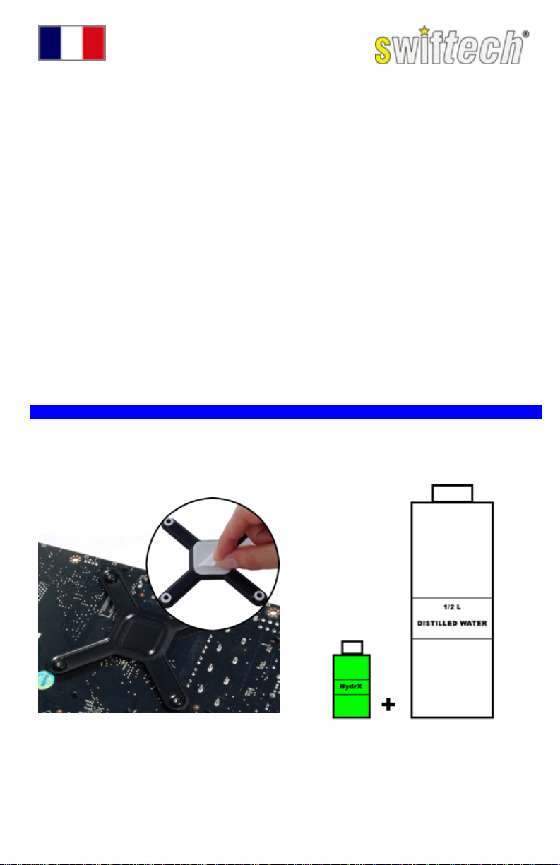
What is needed for the installation that is
• ½ Liter (½ qt) of distilled water (use of
distilled water is mandatory) to mix the
coolant.
• A power supply tester (or a simple paper
clip) to start-up the power supply without
connecting it to the motherboard.
• Rubbing Alcohol or electronic degreaser
for cleaning purposes.
1/ MISCELANEOUS PREPARATIONS
AMD® systems: the Apogee™ Drive is pre-assembled for installation with Intel® socket 775
compatible motherboards. Please refer to the Apogee™ Drive AMD® supplemental installation
guide (page 6) prior to proceeding hereafter.
INTEL® SYSTEMS
H20-120 Compact
not included in the kit?
• A pair of scissors to cut the tubing
• A flat and a Philips screw drivers to fasten
the components
• A pair of long nose pliers to fasten the hose
clamps
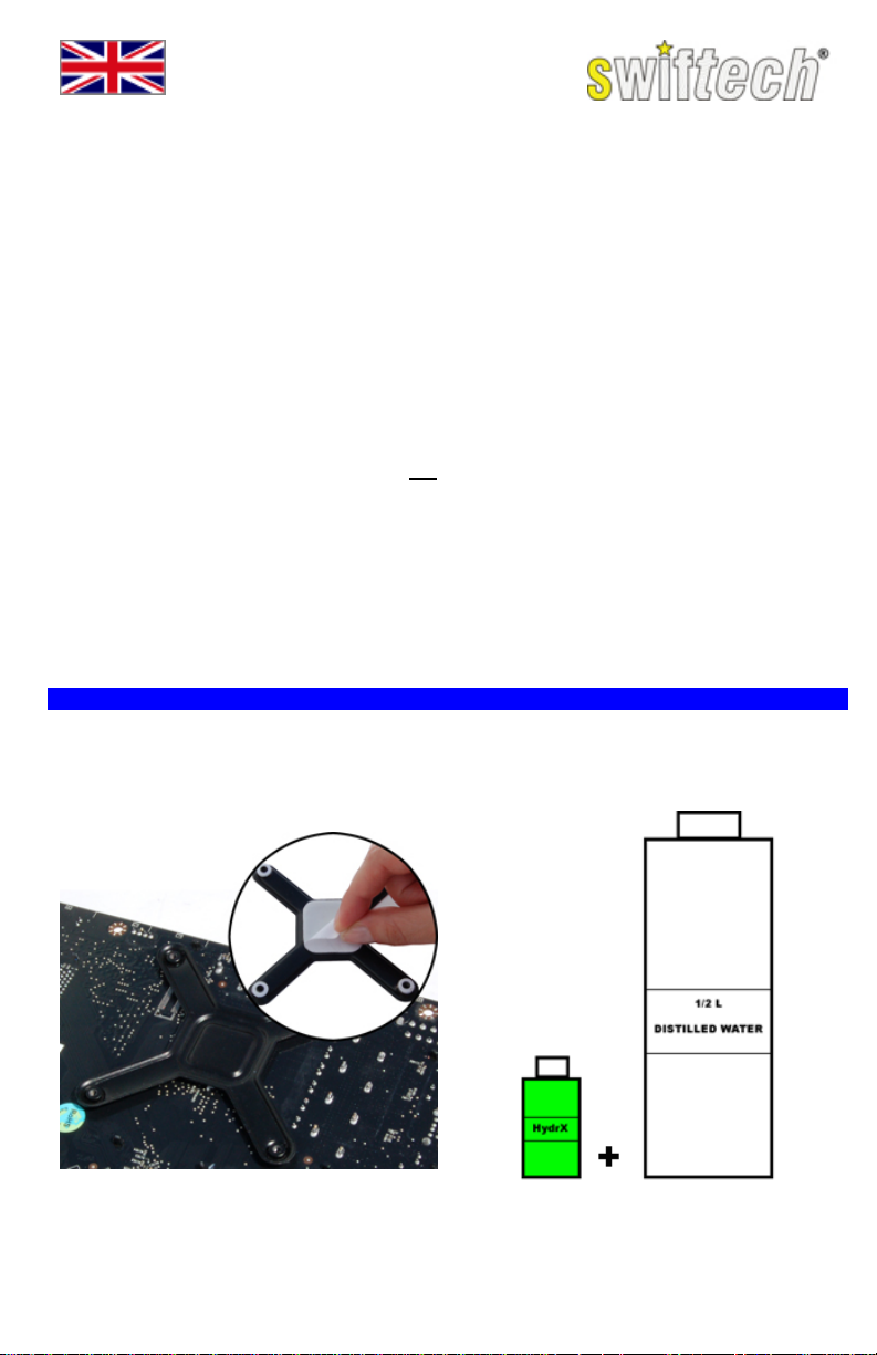
Peel-off the protective paper from the back-plate
stickers, and press the back-plate in place
behind the motherboard socket, then install the
motherboard inside the case following
manufacturer instructions.
Mix the supplied bottle of Hydrx concentrated
coolant to ½ Liter (½ qt) of distilled water.
Page 1
Page 4

Install the fan using the provided screws and
fasten the screws with the provided retaining
nylon washer to hold them in place.
TIP: How to decide in what direction the fan
OUT TO IN (fan label facing in as shown in the
example):
Pros: Much lower CPU temperature.
Cons: Potentially more heat inside the case
(OK if good case ventilation), dust will collect
on radiator & fan and require more frequent
maintenance.
IN TO OUT (fan label facing out):
Pros: Lower case temperature (this setup is a
must in poorly ventilated systems), lower
maintenance (regular dust filter cleaning is still
required),
Cons: Higher CPU temps
should blow?
Attach the tubes to the Apogee™ Drive fittings and clamp them as shown. The clamps should
always be completely closed to provide a proper seal.
2/ MOCKUP INSTALLATION
It is necessary to temporarily position the elements of the kit in the case in order to evaluate the
appropriate length of tubing needed between components. Fully tightening the screws will not be
necessary for this step.
Fasten the screws just enough to hold the
radiator in place.
Fasten the screws just enough to hold the
Apogee™ Drive in place.
Page 2
Page 5
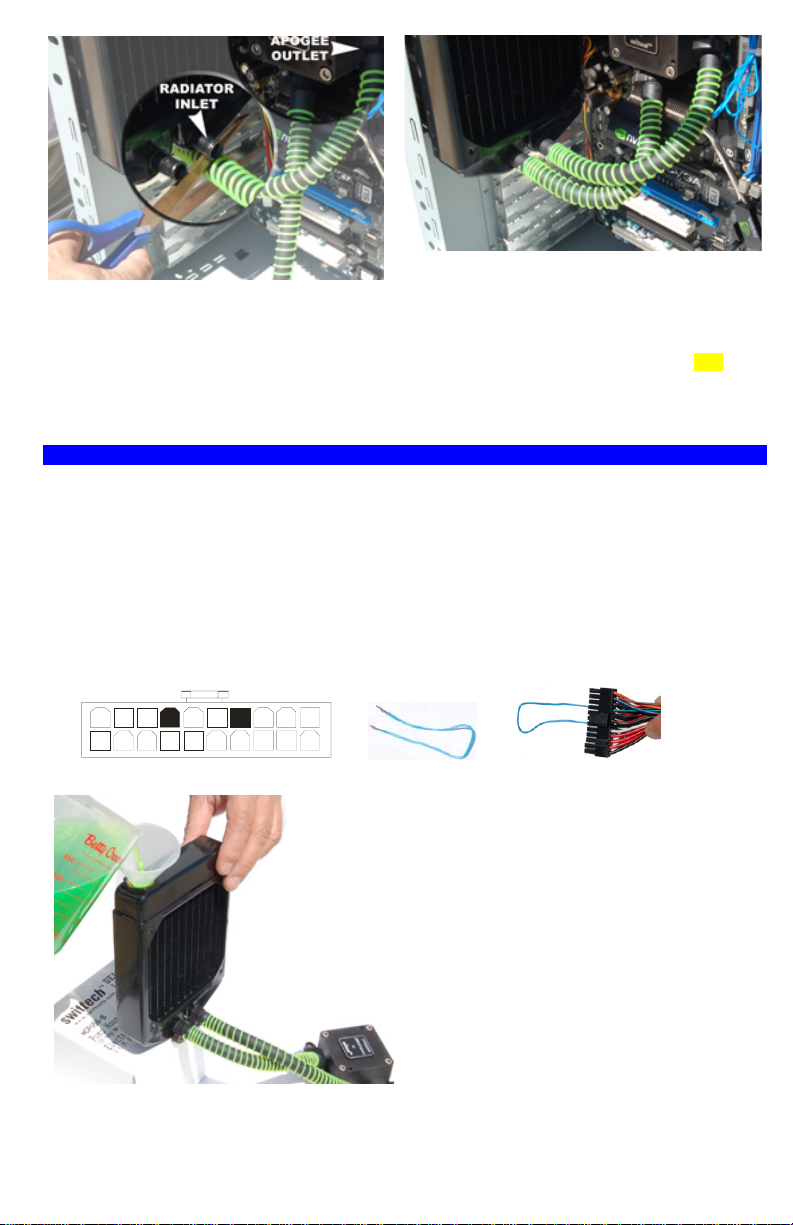
1. Route the Apogee™ Drive Outlet Tube to
the Radiator Inlet Fitting leaving sufficient
slack in the tube to prevent kinks, and then cut
it.
2. Pull the coils back about 1 inch to clear
enough space for the upcoming clamps, and
then push the tube onto the fitting.
3. Adjust the second tube to the radiator, cut it to
length then push the tube onto the fitting.
4. You can now remove the Liquid cooling system
from the case to complete the next step. TIP:
Now, install and fasten the clamps to the radiator
fittings while the liquid cooling system is on your
bench table, it will be more convenient!
3/ FILLING-UP AND TESTING THE SYSTEM
In order to fill-up the liquid cooling system with coolant and test it, you will need to be able to run
the pump. This necessitates that you start-up the power supply while it is not being connected to
the motherboard.
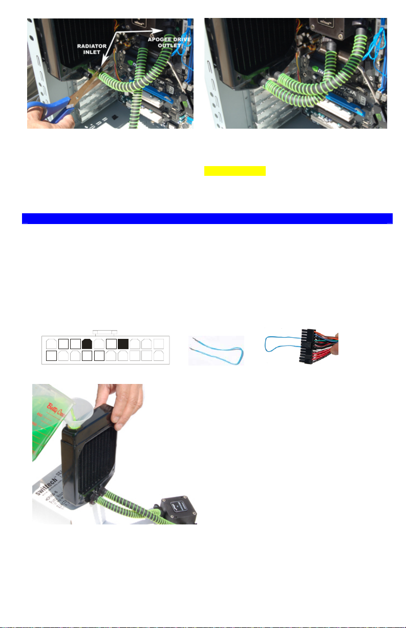
It is possible to turn the PSU on and off with its power switch by using a simple paper clip to
connect pin 14 (PS-ON – GREEN) to any BLACK wire (ground) on the 20 pin ATX connector as
shown hereafter. However, because of the possibility of use r error, which could result in short
circuits, damage to the equipment and/or personal injury, we recommend using a power-supply
tester instead. A wide variety of these common and inexpensive devices is available on the Internet
(Google key word: “PSU tester”), and among Swiftech resellers.
Green
14
Black
Place the system on your bench table, with the
radiator positioned higher than the pump and
pour coolant into the radiator fill-port until full.
Be careful not to overflow!
Now connect the 4-pin Molex connector of the
Apogee™ Drive to your power supply, and
switch-on the PSU. Note that the pump has a 3
seconds delay.
As the device is energized, you should hear the
noise of liquid and air rapidly rushing thru the
pump; immediately after that, the pump noise
level will noticeably decrease and turn to a
gentle hum indicating that the fluid is circulating
normally.
Top-off the radiator with coolant, and allow the
system to run for 30 minutes to an hour on your
bench while periodically inspecting it for leaks.
Control the level one last time, and top-off with
coolant as necessary. Then close the fill-cap
firmly to assure a good seal.
Your system is now ready for use.
Page 3
Page 6
4/ FINAL INSTALLATION
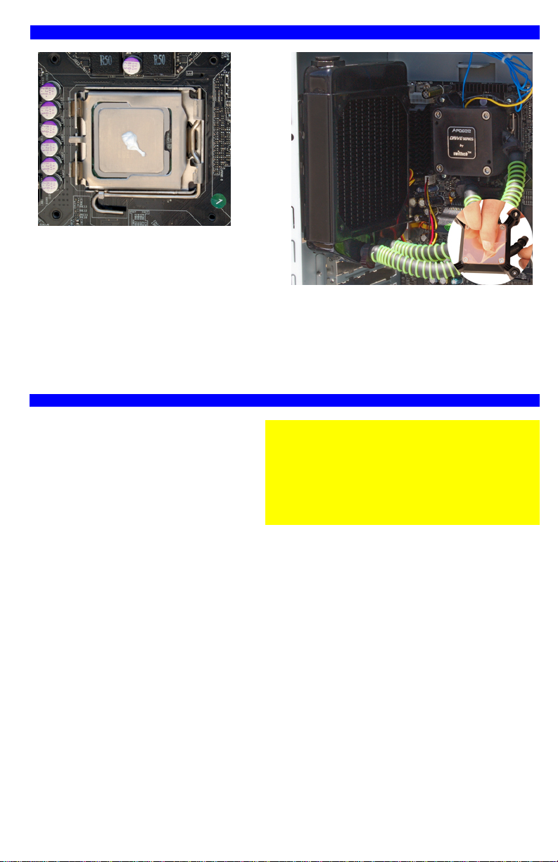
1. Apply the provided Arctic Céramique™
thermal grease at the center of the CPU as
shown above.
2. Fasten the radiator to the fan by tightening
all four screws.
3. Peel-off the protective plastic film from the
Apogee™ Drive copper base plate, and wipeoff the copper with alcohol or with electronics
degreaser.
5/ ELECTRICAL CONNECTIONS AND PRODUCT USAGE
Apogee™ Drive connections
• Power: connect the 4-pin Molex
connector to your power supply.
• RPM sensor: connect the 3-pin single
wire connector to the motherboard
CPU fan header.
Fan connections
• For 12V fan o perations simply connect the 3-pin fan connector to a motherboard fan header.
• For 7V fan operations connect the provided 12 to 7 volt adapter to the fan, and then connect
the adapter to a motherboard fan header.
Note: many modern motherboards now have the ability to adjust the fan speed via the
motherboard BIOS, or under windows (nVidia® nTune for example). If you own such motherboard,
there is no need to use the 12 to 7 volt adapter.
Which one to choose? 12v or 7v?
Please refer to the O/C Meter table
The graduated quadrant indicates the level of Overclock: from zero for stock CPU speed, to 9 for
Extreme Overclock. The red-shaded area indicates the level that can be attained depending on
system configuration.
The noise symbols reflect the speed of the fan.
4. Fasten the Apogee™ Drive to the processor
by tightening all four screws progressively and
in a cross pattern until you reach a firm positive
lock. Cycle thru the four screws twice to make
sure that you have equal tension on all four.
Critical recommendation:
Connecting the pump RPM sensor to the CPU fan
header is critical in order to monitor the pump. All
modern motherboards have safety features that
you can enable in the BIOS that will shut down the
power in the event of a CPU fan failure or in this
case in the event of a pump malfunction.
Page 4
Page 7

6/ OTHER SWIFTECH LIQUID COOLING PRODUCTS (PLEASE VISIT WWW.SWIFTECH.COM)
Are you having a problem installing your radiator inside the case?
The MCB120-“Radbox” universal radiator mounting adapter will allow you
to setup your radiator to the back of practically any chassis, and it can
boost performance too!
Do you need to cool your Graphics Card(s) too?
Check out the Stealth and MCW60 Waterblocks, they are considered by
many as best in the world!
Need to cool the chipset?
The MCW30 chipset Waterblock is the most versatile of its kind on the
market.
Do you need additional cooling capacity?
The Quiet Power™ MCR series radiators have been designed for optimum cooling at the lowest
possible noise. You can add a second radiator to your setup, or upgrade to a larger one!
Page 5
Page 8
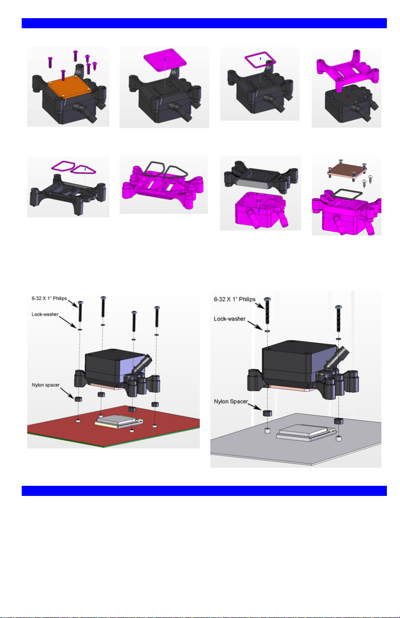
7/ SUPPLEMENTAL AMD® INSTALLATION GUIDE
a/ Apogee Drive conversion from Intel Socket 775 to AMD Universal housing
1. Loosen and set
aside all 6 screws as
shown above.
5. Remove the o-rings
from the socket 775
housing …
b/ Installation on the motherboard
2. Remove and set aside
the copper base-plate.
…and install them to the
AMD housing.
3. Remove and set
aside the base-plate
o-ring.
6. Place the AMD
housing onto the
Apogee Drive body.
4. Remove the
socket 775
housing.
7. Install o-ring,
base plate, and
fasten all 6
screws.
Socket AM2
8. MAINTENANCE
Check your coolant level once a year; the radiator fill-cap features a dip-stick for your
convenience,
As long as your system has been properly sealed, refill should not be necessary for up to 5
years. If needed, you can top-off the level with the coolant mix recommended above.
Clean the computer filters as frequently as necessary. They should be free of dust at all times.
Regularly inspect your radiator and fan for dust, and clean as necessary.
Socket 754/939/940, and F
Page 6
Page 9
Guide D’installation
Introduction
Félicitations pour votre achat du kit Swiftech™ H20-120 COMPACT ! Bien que ce guide ait été
conçu pour faciliter au mieux l’installation du produit, il s’adresse à l’utilisateur avisé en matière
d’installation de composants électroniques.
Généralités
Il est conseillé de lire ce document dans sa totalité avant de commencer l’installation.
Débrancher le PC du secteur afin d’éviter tout risque de court-circuit lors du montage des
composants.
La prise ATX de la carte mère doit être débranchée lors de l’installation du système de
refroidissement.
Assurez-vous toujours de tester le circuit pour toutes fuites éventuelles avant de remettre les
composants électroniques en service !
De quoi aurai-je besoin et qui n’est pas inclus avec ce kit?
• ½ Litre d’eau distillée pour faire le
mélange (usage obligatoire)
• Un testeur d’alimentation (ou tout
simplement un trombone) pour démarrer
l’alimentation.
• De l’alcool ou un dégraissant pour
composants électroniques.
1/ PREPARATIONS DIVERSES
Pour les systèmes AMD® , l’Apogee™ Drive est pré configuré pour cartes mères Intel® socket
775. Veuillez vous référer au guide supplémentaire pour AMD® (page 12) avant de continuer ciaprès.
SYSTEMES INTEL®
H20-120 Compact
• Une paire de ciseaux pour couper les tuyaux
• Un tournevis cruciforme
• Une pince à becs
Retirez le papier protecteur de l’autocollant au
dos de la plaque de renforts et installez celle-ci
au dos de la carte mère. Réinstallez ensuite la
carte mère dans le boîtier selon les instructions
du constructeur.
Mélangez la bouteille de HydrX fournie à ½ litre
d’eau distillée.
Page 7
Page 10

Utilisez les vis cruciformes fournies pour
installer le ventilateur, puis les rondelles de
rétention en nylon afin de le maintenir en place.
Comment choisir le sens d’écoulement d’air
du ventilateur ?
De l’extérieur vers l’intérieur (étiquette du
ventilateur tournée vers l’intérieur du boîtier)
Avantage: température du microprocesseur
beaucoup plus basse.
Inconvénients: température intérieure du boîtier
plus haute, accumulation de poussière sur le
radiateur et dans le boîtier (maintenance
fréquente).
De l’intérieur vers l’extérieur (standard)
Avantages: température du boîtier plus basse,
pas de maintenance autre que normalement
requise (nettoyage des filtres à poussière)
Inconvénient:: température du microprocesseur
plus haute
Enfoncez les tuyaux sur les embouts de l’ Apogee™ Drive et fixez-les avec les serre-joints
fournis. Serrez soigneusement à fond comme indiqué dans l’encart.
2/ INSTALLATION TEMPORAIRE
Il est nécessaire de mettre les éléments du kit temporairement en place à l’intérieur du boîtier afin
de déterminer la longueur des tuyaux.
Accrochez le radiateur. Serrez légèrement les
vis simplement pour le maintenir en place.
Posez l’Apogée sur le microprocesseur. Serrez
légèrement 2 des vis en diagonale simplement
pour le maintenir en place.
Page 8
Page 11

1. Positionnez le tube coté sortie de l’
Apogee™ Drive en face de l’embout d’entrée
du radiateur en prenant soin de lui laisser du
jeu, puis coupez le surplus et enfoncez le tuyau
sur l’embout.
2. Laissez 3cm de tuyau à nu afin de pouvoir
installer le serre-joint par la suite.
3. Ajustez le second tuyau de la même manière.
4. On peut à présent ressortir le système de
refroidissement du boîtier afin de procéder à son
remplissage. Conseil pratique : installer les serrejoints sur les embouts du radiateur une fois le
système dehors. C’est plus pratique !
3/ REMPLISSAGE ET TEST DU SYSTEME
Il est nécessaire de faire tourner la pompe afin de procéder au remplissage et au test du système
de refroidissement. Ceci requiert de pouvoir allumer l’alimentation sans qu’elle ne soit branchée
sur la carte mère.
On peut utiliser l’interrupteur de l’alimentation en connectant la broche 14 de la prise ATX (fil vert)
à un fil de terre (noir) à l’aide d’un simple trombone. En raison des risques d’erreurs par les
utilisateurs qui pourraient résulter en dommages matériels ou corporels, nous recommandons à la
place de la méthode ci-dessus l’utilisation d’un testeur d’alimentation (mot clef google: ‘’ testeur
d’alimentation’’).
Green
14
Black
1. Placez le radiateur en hauteur par rapport à
l‘Apogée Drive et remplissez le à ras bord..
Attention à ne pas déborder !
2. Branchez à présent la prise Molex de
l’Apogée Drive sur l’alimentation.
3. Allumez l’alimentation (à noter que la pompe
de l’Apogée Drive à un délai de 3 secondes).
Dès que la pompe démarre, vous entendrez
clairement la pompe caviter bruyamment en
raison du mélange d’air et d’eau qui circule
rapidement à l’intérieur. En quelques secondes,
le bruit se régularisera à un bourdonnement
léger, indiquant que le liquide circule
normalement.
4. Remettez le liquide de refroidissement à
niveau, et laissez tourner le système de 30
minutes à une heure, en prenant soin
d’inspecter les fuites éventuelles.
5. Contrôlez et ajustez le niveau de liquide une
dernière fois, et fermez le bouchon de
remplissage.
Le système de refroidissement est prêt à
l’emploi.
Page 9
Page 12

4/ INSTALLATION FINALE
1. Déposez une petite quantité de graisse
thermique Arctic Céramique™ sur le
microprocesseur.
2. Accrochez le radiateur au ventilateur et
serrez les 4 vis de montage.
3. Retirez le film protecteur de la base en
cuivre de l’Apogée Drive comme indiqué en
encart, et nettoyez celle-ci avec de l’alcool
avant de l’installer.
5/ CONNEXIONS ELECTRIQUES ET UTILISATION DU PRODUIT
Connexions de l’Apogee™ Drive
• Puissance : connectez la prise Molex 4
broches à l’alimentation.
• Compte-tours : connectez la prise 3
broches (1 seul fil) à l’emplacement de
la carte mère réservé au ventirad.
Connexions du ventilateur
• Pour utiliser le ventilateur à 12 v (pleine puissance) simplement connecter la prise 3 broches
de celui-ci à une prise 3 broches de la carte mère.
• Pour utiliser le ventilateur à puissance réduite (faible niveau sonore), branchez l’adaptateur
12v à 7v fournis avec le kit sur le ventilateur, et branchez l’adaptateur sur une prise de la
carte mère.
Conseil pratique : de plus en plus de carte mères modernes sont dotées d’utilitaires qui permettent
de régler la puissance du ventilateur dans le BIOS et même sous Windows (nTune par exemple).
Dans ce cas, l’adaptateur 12v à 7v ne sera pas nécéssaire.
Comment choisir entre 12 volts ou 7 volts ?
L’ O/C mètre (‘’O/C’’ pour overclock) ci-après permet d’établir une relation entre la configuration de
votre PC et la puissance thermique nécessaire pour le système de refroidissement.
Le quadrant gradué indique le niveau d’overclock du microprocesseur où zéro est la fréquence
d’origine, et 9 est un Overclock extrême.
Le symbole de bruit indique la vitesse de ventilateur à utiliser en fonction du niveau sonore désiré
par rapport à la configuration de votre PC.
4. Installez l’Apogée Drive sur le
microprocesseur. Serrez les vis graduellement
et en croix. Serrez fermement mais sans
excès, et faites deux passes en final afin de
bien sentir que la tension est identique aux 4
vis.
Conseil Important :
Connecter la prise de compte-tours à la prise
ventirad de la carte mère est d’une importance
critique! Toutes les cartes mères modernes sont
équipées d’utilitaires de surveillance qui éteignent
le PC en cas de panne du système de
refroidissement. Bien contrôler le fonctionnement
de cet arrêt d’urgence !
Page 10
Page 13

6/ AUTRES PRODUITS DE REFROIDISSEMENT LIQUIDE SWIFTECH (www.swiftech.com)
Problème d’installation du radiateur à l’intérieur du boîtier?
Le boîtier de montage radiateur universel MCB120-“Radbox” vous
permettra d’installer le radiateur au dos de pratiquement n’importe
quel boîtier PC. Il permet aussi un gain important en température !
Voulez-vous aussi refroidir la carte graphique ?
Les blocks de refroidissement liquide MCW60 et ‘’Stealth’’ sont
considérés parmi les meilleurs au monde !
Voulez-vous aussi refroidir le chipset?
Le block de refroidissement liquide MCW30 est parmi les plus
versatiles sur le marché.
Avez-vous besoin d’une capacité de refroidissement supplémentaire?
Les radiateurs de la série ‘’Quiet Power™’’ sont conçus pour une dissipation thermique maximum
à un niveau sonore minimum. Vous pouvez rajouter un deuxième radiateur de 120mm, ou
changer le radiateur existant pour un double, ou même un triple !
Page 11
Page 14

7/ GUIDE D’INSTALLATION SUPPLEMENTAIRE POUR AMD®
a/ Conversion de l’Apogée Drive du format socket 775 au format multiple pour AMD
1. Devissez les 6 vis
du socle comme ci-
2. Retirez la plaque en
cuivre
dessus
5. Retirez les joints
toriques de la demi
…et réinstallez-les sur
la demi coque AMD
coque 775…
b/ Installation sur la carte mère
3. Retirez le joint
torique
6. Mettez la demi coque
AMD en place sur
l’Apogée
4. Retirez la demi
coque plastique
775.
7. Réinstallez
joint torique et
plaque en cuivre
à l’aide des vis
existantes.
Socket AM2
Socket 754/939/940, and F
8/ MAINTENANCE
Vérifier votre niveau de liquide réfrigérant une fois par an. Le bouchon de radiateur comporte un
jaugeur pour votre convenance. Tant que votre système a été correctement scellé, le remplissage
ne devrait pas être nécessaire pendant environ 5 années. Si nécessaire, vous pouvez ajuster le
niveau avec le mélange de liquide réfrigérant recommandé ci-dessus. Nettoyer les filtres
d'ordinateur fréquemment ou selon les besoins. Ils devraient être exempts de poussière à tout
moment. Inspecter régulièrement votre radiateur et ventilateur pour assurer l'absence de la
poussière, et pour les nettoyer selon les besoins.
Page 12
Page 15

Montageanleitung
Einleitung
Glückwunsch und vielen Dank für den Kauf des H20-120 COMPACT Komplettsets von
Swiftech® . Die Installation des Systems ist bestimmt für die erfahrenen Benutzer, die gut die
Computer Komponente installieren können.
Empfehlungen
Bevor Sie die Installation beginnen, lesen Sie bitte sorgfältig die ganze Montageanleitung.
Als Sie das Komplettset installieren, schalten Sie dem Computer aus, um einen Kurzschluss
zu vermeiden.
Als Sie das Wasserkühlungsystem installieren, müssen Sie das Atx Stecker auschalten.
Bevor sie den Computer starten, kontrollieren Sie immer, dass Sie keine Leck haben!
Was brauche ich und was wird in dem Komplettset nicht geliefert?
• ½ Liter distilliertes Wasser (Sie müssen es
mit HydrX mischen).
• Netzteil Testgerät (oder einfacher eine
Büroklammer), um das Netzteil zu starten.
• Ein bisschen Alkohol um die Komponente
zu putzen.
1/ VERSCHIEDENEN VORBEREITUNGEN
AMD® Systems: l’Apogee® Drive wird für Intel® Motherboards (Sockel 775) vormontiert. Mit
AMD® müssen Sie die Befestigung Platte ändern (Die Installation wird Seite 12 erklärt). Wenn es
fertig ist, folgen Sie den nächsten Etappen.
INTEL® System
H20-120 Compact
• Eine Schere um die Schläuche zu schneiden
• Ein Kreuzschlitzschraubendreher
• Eine Flachzange
Sie schälen das Schutzpaper auf die
Befestigungplatte und Sie installieren sie an der
Rückseite des Motherboards. Dann installieren
Sie wieder das Motherboard im Chassis (Sie
folgen den Anleitungen von dem Hersteller).
Sie vermischen die HydrX Flasche und ½ L
destilliertes Wasser.
Page 13
Page 16

Sie benutzen die gelieferte Schrauben, um das
Lüfter zu installieren, dann installieren Sie die
Nylon Scheiben (um das Lüfter zu befestigen).
Wie wählen Sie in welche Richtung muss
Von außen nach innen (die Orientierung des
Lüfters Foto sehen)
Vorteil: Temperatur des Mikroprozessor leiser.
Nachteil: Innertemperatur in dem Chassis
höher, viel Staub (Radiator und im Chassis),
mehre Wartung.
Von innen nach außen (Standard)
Vorteil: Leisere Temperatur im Chassis, kleine
Wartung (nur die Staubfilter zu putzen).
Nachteil : Höher Temperatur von dem
Mikroprozessor
der Lüfter blasen?
• Sie schließen die Schläuche an die Fittings von Apogee® Drive an und Sie befestigen sie mit
den gelieferten Schlauchschellen. Sie drehen sorgfältig die Schlauchschellen mit der
Flachzange fest.
2/TEMPORÄRE INSTALLATION
Um die Länge den Schläuche zu scheren, ist es nötig, die Komponente im Chassis zeitweise zu
installieren. Achtung! es ist temporarisch, bitte schrauben Sie nicht zu viel!
Sie hängen den Radiator und schrauben es
(nicht zu viel).
Sie installieren das Apogee™ Drive auf der
CPU und sie befestigen 2 Schrauben (nicht zu
viel). (es ist besser, dass es nicht bewegt!).
Page 14
Page 17

Sie schätzen die (Schlauch) Länge, die Sie
brauchen, um die Ausgabe von dem
Apogee™Drive an die Eingabe von dem
Radiator anzuschließen. Dann scheren Sie
den Schlauch (Sie behalten 3cm ohne
Smartcoils™ für die Schlauchschellen) und
Sie schließen ein Schlauch an die Ausgabe
von dem Apogée™ Drive an die Eingabe von
Sie benutzen dieselbe Technik, um das zweite
Schlauch zu installieren.
Um das System zu füllen, bauen Sie den Radiator
und das Apogee™ Drive aus dem Chassis aus.
Trick: Es ist leichter, die Schlauchschellen aus
dem Chassis, zu installieren.
dem Radiator an.
3/ FÜLLEN UND KONTROLLIEREN DAS SYSTEM
Um das System zu füllen und zu kontrollieren, muss die Pumpe funktionieren. Sie müssen das
Netzteil starten. Aber, das Netzteil soll nicht an das Motherboard angeschlossen sein deshalb,
schlagen wir 2 Lösungen vor:
Wenn Sie anfänger sind, ist es besser diese Lösung zu wählen: Sie kaufen einen Netzteil
Testgerät (suchen mit Google: „Netzteil Testgerät“).
Für die Anderen: Sie können Pin 14 von dem ATX Stecker (im Allgemeinen ist es grün) an einem
Massekabel (schwarz) mit einer Büroklammer anschließen (aber es gibt Risikos).
Green
14
Black
Sie legen das System an dem Tisch (Radiator
höher als Apogee™Drive) und füllen mit dem
Kühler , bis das Radiator voll ist
Achtung! Überlaufen Sie den Radiator nicht.
Dann schließen Sie das Molex Stecker von
dem Apogee™Drive an das Netzteil an.
Sie starten das Netzteil (der Apogee™ Drive
wird 3 Sekunden später starten). Als Die
Pumpe startet, hören Sie den Lärm von der
Kühlerflüssigkeit und der Luft, die sehr schnell
in der Pumpe zirkulieren. Einige Sekunden
später, ist das Lärm leiser. Das bedeutet, dass
alles in Ordnung ist!
Sie füllen das System (wenn es nicht genug
Kühlerflüssigkeit gibt) und lassen das System
während 30 Minuten bis 1 Stunde
funktionnieren. Achtung! Sie kontrollieren
sorgfältig, dass es keine Leck gibt.
Dann ist das System fertig!
Page 15
Page 18

4/ LETZTE INSTALLATION
1. Sie tragen hauchdünn Warmleitpaste auf
CPU-Kern auf.
2. Sie hängen das Radiator mit dem Lüfter
und befestigen die 4 Schrauben.
3. Sie schälen das Plastikschutz von der
Kupferplatte) (gezeigt rechte Foto). Bevor
Sie sie installieren, putzen Sie sie mit
Alkohol.
5/ ANSCHLÜSSE UND DAS SYSTEM BENUTZEN
Wie schließen Sie den l’Apogee® Drive an?
• Leistung: Sie schließen den 4 Pins Molex
an das Netzteil an
• Drehzahler: Sie schließen das 3 Pins
Stecker an das Motherboards CPU Lüfter
Port an.
Wie schließen Sie den Radiator an?
• Um das Lüfter mit 12V (volle Leistung) zu benutzen, schließen Sie die 3 Pin Molex
Anschluss an die 3 Pin Motherboard Anschluss an.
• Um das Lüfter mit 7V (« quiet Power ») zu benutzen, schließen Sie das Adapter 12V auf 7V
(mit dem Komplettset geliefert) an den Lüfter und danach an den Motherboard Stecker.
Was wählen Sie zwischen 12 und 7 v?
Bitte, lesen Sie das Schema (rechts).
Anmerkung: Die meisten Motherboards haben Programmen, die die Leistung des Lüfters in dem
BIOS regulieren (oder mit Windows auch, zum Beispiel: nVidia® nTune). Auf diesem Fall, ist das
Adapter unnötig.
4. Sie installieren das Apogee™Drive auf der
CPU. Befestigen Sie in Diagonal und
alternierend. (selbe Spannung für jede
Schraube).
Wichtiger Trick :
Das 3 Pins Stecker an das Motherboards CPU
Lüfter Port anschließen, ist sehr wichtig! Die
neuen Motherboards haben Hilfeprogrammen,
die den Computer aushalten, wenn das
Wasserkühlungsystem eine Panne hat.
Aber Sie müssen kontrollieren, dass dieses
Hilfeprogramm läuft.
Wie den Lüfter regulieren? Das hängt von ihrem System ab!
Page 16
Page 19

6/ SWIFTECH OPTIONEN (WWW.SWIFTECH.COM)
Können Sie nicht den Radiator im Chassis installieren?
Mit dem MCB120- Radbox können Sie ihren Radiator in der
Rückseite von (fast) allen Chassis. Besser Leistung!
Die Grafikkarte kühlen ?
MCW60 und ‘’Stealth’’ sind unter den besten in der Welt.
Chipsatz kühlen?
Der MCW30 Chipstz-Kühler ist sehr vielseitig.
Brauchen Sie mehr Kühlung?
Wir haben Die Radiatoren‘’Quiet Power™’kreiert, um die beste Kühlung mit wenigem Lärm zu
geben. Wählen Sie das Radiator (oder die Radiatoren), das Sie wollen : zwei Radiatoren von 120
mm oder einen größer !
Page 17
Page 20

7/ MONTAGEANLEITUNG FÜR AMD® SOCKEL
a/ von Sockel 775 Befestigungplatte zu AMD® Befestigungplatte.
1. Sie bauen die 6
Schrauben aus.
2. Sie bauen die
Kupferplatte aus.
5. Sie bauen die beide
O rings von der 775
Befestigungplatte...
Und Sie installieren sie
in der AMD®
Befestigungplatte.
b/ Installation auf dem Motherboard
3. Sie bauen das O
Ring aus.
6. Dann installieren Sie
die AMD®
Befestigungplatte in
dem Apogee Drive®
Körper.
4. Sie bauen die
Befestigungplatte
aus.
7. Dann
installieren Sie O
Ring +
Kupferplatte und
befestigen die 6
Schrauben.
Sockel AM2
Sockel 754/939/940, und F
8/ WARTUNG
Dein Kühlmittelniveau einmal jährlich überprüfen. Die Heizkörperkappe kennzeichnet einen
ölmeßstab für deine Bequemlichkeit. Solange dein System richtig versiegelt worden ist, sollte das
Wieder füllen nicht für ungefähr 5 Jahre notwendig sein. Wenn es benötigt wird, kannst du das
Niveau mit der Kühlmittelmischung justieren, die oben empfohlen wird. Die Filter des Computers
häufig säubern oder, wie gebraucht. Sie sollten vom Staub frei ständig sein. Deinen Heizkörper
und Ventilator regelmäßig kontrollieren, um das Fehlen Staub sicherzustellen, und sie falls
erforderlich zu säubern.
Page 18
Page 21

Guía de instalación
Introducción
¡Enhorabuena por su compra del kit Swiftech™ H20-120 COMPACT! Aunque esta guía se haya
concebido para facilitar lo mejor posible la instalación del producto, se dirige al usuario advertido
en materia de instalación de componentes electrónicos.
Generalidades
Se aconseja leer este documento en su totalidad antes de empezar la instalación
Desconecte el PC con el fin de evitar todo riesgo de cortocircuito o electrocución durante el
Para la instalación del sistema de enfriamiento, la toma ATX de la placa base debe
¡Asegurase siempre de probar detalladamente que el circuito no tiene fugas, antes de volver
¿De qué tendría necesidad y que no se incluye en este kit?
• ½ Litro de agua destilada para hacer la
mezcla (uso obligatorio)
• Un probador de fuentes u otro utensilio
para arrancar la fuente de alimentación.
• Alcool de 90° o un desgrasante para
componentes electrónicos.
1/ DIVERSAS PREPARACIONES
Sistemas AMD®: el Apogee® Drive está pre configurado para las placas base Intel® socket 775.
Para AMD refiérase a la guía suplementaria AMD® (página 24) antes de continuar.
SISTEMAS INTEL
montaje de los componentes.
desconectarse.
a poner los componentes electrónicos en servicio!
H20-120 Compact
• Un par de tijeras para cortar los tubos.
• Un destornillador Philips.
• Una pinza de punta.
Retirar la hoja protectora de autoadhesivo de la
placa de refuerzos e instalar la placa sobre la
placa base. Reinstalar a continuación la placa
base en la caja según las instrucciones del
fabricante.
Mezclar la botella de HydrX en ½ litro de agua
destilada.
Page 19
Page 22

Utilizar los tornillos Philips proporcionados para
instalar el ventilador así como los discos de
retención de nailon con el fin de mantenerlos
en su lugar.
¿Cómo elegir el sentido de evacuación del
aire del ventilador?
De exterior hacia el interior (etiqueta de cara
al interior de la caja)
Positivos: temperatura del microprocesador
mucho más baja.
Negativos: más alta temperatura interior de la
caja, acumulación de polvo sobre el radiador y
sobre la caja (mantenimiento frecuente).
Del interior hacia el exterior (estándar)
Positivos: temperatura de la caja más baja,
mantenimiento normalmente requerido
(limpieza de los filtros y polvo)
Negativos: más alta temperatura del
microprocesador.
Insertar los tubos sobre las conteras del Apogee® Drive y fijarlos con los cierra juntas
proporcionados. Cuidadosa y firmemente ajustarlos tal como se indica.
2/ INSTALACION TEMPORAL
Es necesario simular la instalación del kit al interior de la caja con el fin de determinar la longitud
de los tubos.
Colocar el radiador. Ligeramente apretar los
tornillos con el fin de mantenerlo en su lugar.
Colocar el Apogee sobre el microprocesador.
Ligeramente apretar 2 tornillos, en diagonal,
con el fin de mantenerlo en su lugar.
Page 20
Page 23
Comenzando por la salida del Apogee®
Drive colocando la extremidad del tubo frente
a la contera de entrada del radiador
verificando que quede un poco de juego,
luego cortar el excedente e insertan el tubo
en la contera. Dejar 3cm de tubo desnudo
con el fin de poder instalar el cierra juntas
después.
Ajuste el segundo tubo de la misma manera.
Ahora se puede retirar el sistema de enfriamiento
de la caja con el fin de proceder a su relleno.
Consejo práctico: instalar los cierra juntas sobre
las conteras del radiador una vez el sistema se
encuentre fuera de la caja. ¡Es más fácil!
3/ RELLENO Y TEST DEL SISTEMA
Es necesario voltear la bomba con el fin de proceder al relleno y a la prueba del sistema de
refrigeración. Esta operación requiera encender la fuente de alimentación sin que ella se
encuentre conectada a la placa base.
Puede utilizar el interruptor de la fuente de alimentación haciendo un puente entre el PIN 14 del
conector ATX (cable verde) al cable de tierra (negro). Debido a los riesgos y errores que pueden
correr los usuarios que podrían causar daños materiales o corporales; recomendamos, en vez de
aplicar el método aquí arriba mencionado, la utilización de un probador de fuente de alimentación
(palabra clave google: ( ‘’ Probador de fuentes de alimentación ATX’‘).
Green
14
Black
Con relación al Apogee Drive, coloque el
radiador a la misma altura y llene hasta el
borde. ¡Atención no debe desbordarse!
Conecte ahora la toma Molex del Apogee Drive
en la fuente de alimentación.
Encienda la fuente (tener en cuenta que la
bomba del Apogee Drive tarda 3 segundos en
arrancar). En cuanto la bomba funcione, oirán
clara y ruidosamente la mezcla de aire y liquido
que circula rápidamente al interior. Al cabo de
unos segundos, el ruido se regularizará y un
zumbido ligero, indicara que sólo el líquido
circula normalmente.
Vuelva a agregar el líquido de enfriamiento
hasta el buen nivel, y deja funcionar el sistema
entre 30 minutos a una hora. Constate que no
haya fugas.
Controle y ajuste el nivel de líquido por última
vez, y cierre el tapón de relleno.
El sistema de refrigeración completamente
hermético está listo para su empleo.
Page 21
Page 24

4/ INSTALLATION FINALE
1. Deposite una pequeña cantidad de grasa
térmica Arctic cerámica ™ sobre el
microprocesador.
2. Ajuste el radiador al ventilador y apriete
los 4 tornillos de montaje.
3. Retire la protección plástica de la base en
cobre del Apogee Drive tal como se indica
y limpie ésta con alcohol de 90° antes de
proceder a la instalación.
5/ CONEXIONES ELÉCTRICAS Y UTILIZACIÓN DEL PRODUCTO
Conexiones del Apogee™ Drive
• Potencia: conecte la toma Molex a los
4 pines de la alimentación.
• Cuentavueltas: conecte la toma de 3
pines (un solo cable) a la placa base
en el lugar reservado al ventilador.
Conexiones del ventilador
• Para utilizar el ventilador de 12v (plena potencia) conectar simplemente la toma de 3 pines de
éste a la toma de 3 pines de la placa base.
• Para utilizar el ventilador a potencia reducida (bajo nivel sonoro), conectar el ad aptador de
12v en 7v, proporcionados con el kit, sobre el ventilador, y conecte el adaptador sobre la
toma de la placa base.
Consejo práctico: Todas las buenas placa base actuales están provistas con un útil que permite
regular la potencia del ventilador en el BIOS e incluso en Windows (nTune por ejemplo). En ese
caso, el adaptador de 12v a 7v no será necesario.
4. Instale el Apogee Drive sobre el
microprocesador apretando los tornillos en
cruz y poco a poco. Apretar firmemente
pero sin exceso, y hacerlo dos veces al
final para cerciorarse si la tensión es
idéntica en los 4 tornillos.
Consejo Importante :
¡Conectar la toma del cuentavueltas a la toma del
ventilador de la placa base es de una importancia
capital! Todas las buenas placa base actuales
están provistas con un útil de vigilancia que apaga
el PC en caso de avería del sistema de disipación
térmica. ¡Controlar cuidadosa y detalladamente el
funcionamiento de este sistema de emergencia!
¿Cómo elegir entre 12 ó 7 voltios?
El O/C (‘’ O/C’ ’ para el overclock) en lo sucesivo, permite establecer una relación entre la
configuración del PC y la potencia térmica necesaria para el sistema de enfriamiento.
El cuadrante graduado indica el nivel del overclock del microprocesador donde cero es la
frecuencia de origen y 9 un overclock extremo.
El símbolo de ruido indica la velocidad de ventilador que debe utilizarse en función del nivel
sonoro deseado con relación a la configuración de su PC.
Page 22
Page 25

6/ OTROS PRODUCTOS DE REFRIGERACION LÍQUIDA DE SWIFTECH (www.swiftech.com)
¿Problema de instalación del radiador al interior de la caja?
La caja de montaje del radiador universal MCB120- “Radbox” les
permitirá instalar el radiador en la parte trasera de casi todas las
cajas PC. Su gran ventaja: el intercambio térmico se efectúa fuera
del sistema.
¿Quiere igualmente refrigerar la tarjeta gráfica?
¡Los bloques de refrigeración líquida MCW60 y ‘’Stealth’’ se
consideran los mejores del mundo!
¿Quieren también enfriar el chipset?
El bloque de disipación térmica líquida MCW30 es uno de los más
versátiles del mercado.
¿Requiere una capacidad de enfriamiento suplementaria?
Los radiadores de la serie ‘’Quiet Power ™’’ se conciben para una disipación térmica máxima con
un nivel sonoro mínimo. ¡Pueden añadir un segundo radiador de 120mm, o cambiar el radiador
existente por un doble, o incluso un triple!
Page 23
Page 26

7/ GUÍA DE INSTALACIÓN SUPLEMENTARIA PARA AMD®
a/ Conversión del Apogee Drive del formato socket 775 al formato múltiple para AMD
1. Desatornille los 6
tornillos del zócalo
como se indica.
5. Retire las juntas
tóricas del casco
775…
b/ Instalación en la placa base.
2. Retire la placa de
cobre.
… Y reinstalarlos
sobre la mitad del
casco correspondiente
a AMD
3. Retire la junta tórica 4. Retire la mitad
6. Disponga la mitad
casco correspondiente
a AMD en el Apogee.
del casco plástico
775.
7. Reinstale la
juntada tórica y
placa en cobre
con los tornillos
existentes.
Socket AM2
Socket 754/939/940, & F
8/ MANTENIMIENTO
Comprobar tu nivel del líquido refrigerador una vez al año. El casquillo de radiador ofrece una
varilla de nivbl para tu conveniencia. Mientras tu sistema se haya sellado correctamente, el
rellenar no debe ser necesario por cerca de 5 años. Si está necesitado, puedes ajustar el nivel con
la mezcla del líquido refrigerador recomendada arriba. Limpiar los filtros de la computadora con
frecuencia o según lo necesitado. Deben estar libres del polvo siempre. Examinar regularmente tu
radiador y ventilador para asegurar la ausencia del polvo, y para limpiarlos cuanto sea necesario.
Page 24
Page 27

DISCLAIMER: While all efforts have been made to provide the most comprehensive tutorial
possible, Swiftech™ assumes no liability expressed or implied for any damage(s) occurring to your
components as a result of using Swiftech™ cooling products, either due to mistake or omission on
our part in the above instructions, or due to failure or defect in the Swiftech™ cooling products. In
addition, Swiftech™ assumes no liability, expressed or implied, for the use of this product, and
more specifically for any, and all damages caused by the use of this product to any other device in
a personal computer, whether due to product failure, leak, and electrical short, and or electromagnetic emissions. WARRANTY: Our products are guaranteed for 12 months from the date of
delivery to the final user against defects in materials or workmanship. During this period, they will
be repaired or have parts replaced provided that: (I) the product is returned to the agent from which
it was purchased; (II) the product has been purchased by the end user and not used for hire
purposes; (III) the product has not been misused, handled carelessly, or other than in accordance
with any instructions provided with respect to its use. This guarantee does not confer rights other
than those expressly set out above and does not cover any claims for consequential loss or
damage. This guarantee is offered as an extra benefit and does not affect your statutory rights as a
consumer.
IMPORTANT ! Malgré tous nos efforts pour vous offrir un guide technique le plus explicite
possible, des erreurs ou omissions sont possibles. La Société Swiftech® ne pourra pas être tenue
pour responsable pour tous dommages survenus aux composants suite à l’utilisation des produits
de refroidissement Swiftech®, dommages dus à des erreurs ou oublis de notre part dans les
instructions ci-dessus mais également dus à un mauvais fonctionnement ou un défaut des produits
Swiftech®. Les images utilisées ci-après ne sont pas nécessairement contractuelles. GARANTIE :
Nos produits bénéficient d’une garantie de 12 mois à partir de la date d’achat, garantie couvrant
les défauts de matériaux ou de fabrication. Pendant cette période, les produits seront réparés ou
remplacés si les conditions suivantes sont respectées : (I) le produit doit être retourné au
revendeur où il a été acheté; (II) le produit a été acheté et utilisé par l’utilisateur final, il n’a pas été
loué ; (III) le produit n’a pas été mal utilisé, manipulé sans attention ou sans respect des règles
d’utilisation mentionnées. Cette garantie ne confère pas d’autres droits que ceux clairement cités
plus haut et ne couvre aucune demande de dommages et intérêts. Cette garantie est offerte
comme un extra et n’affecte pas vos droits statutaires de consommateur.
WICHTIG: Trotz unseren Anstrengungen, um eine klare und verständliche Montaganleitung
vorzuschlagen, können sie trotzdem Fehler machen.Auf diesem Fall, übernimmt swiftech keinerlei
Haftung für Schäden, die durch den Einbau oder die Anwendung entstanden sind oder, die auf ein
Vergessen in der Montageanleitung, ein schlechtes Funktionieren, oder auf Defekten der swiftech
Produkts anzurechnen sind.Außerdem übernimmt Swiftech keinerlei Haftung für die Verwendung
von diesem Produkt oder anderen und für die Schäden, die von dieser Verwendung für eine
andere Funktion verursacht werden, selbst wenn es Lecks, Defekt, Kurschluss oder
elektromagnetischen Emissionen ist. GARANTIE: Unsere Produkte sind mit Garantie während 12
Monaten, die Garantie beginnt den Tag des Verkaufs, schält die Materialdefekten oder die
Fertigung aus. Durch dieser Periode, werden die Produkten repariert oder geändert, wenn Sie
diese Bedingungen einhalten : 1) : Geben Sie den Produkt zurück, wohin Sie ihn gekauft haben ;
2) der Produkt wird von dem Verbraucher gekauft und angewendet, der hat ihn nicht vermietet ; 3)
Der Produkt muss gut angewendet sein (einhaltend die Montaganleitung)Die Garantie gibt Ihnen
kein anderes Recht und schält keinerlei Haftung für Schadenersatz aus. Sie ist geschenkt und
ändert ihre Rechte als Verbraucher nicht.
I¡IMPORTANTE! A pesar de todos nuestros esfuerzos para ofrecerles a una guía técnica lo más
explícita posible, errores u omisiones son posibles. La sociedad Swiftech® no podrá ser
considerada como responsable por los daños ocurridos a los componentes del sistema a raíz de la
utilización de cualquiera de sus productos. Ni de los daños debidos a errores u olvidos por nuestra
parte en las instrucciones de instalación o debidas a un mal funcionamiento o defecto de alguno
de sus productos. Las imágenes utilizadas a continuación no son necesariamente contractuales.
GARANTÍA: Nuestros productos benefician de una garantía de 12 meses a partir de la fecha de
compra, la garantía cubre los defectos de fabricación de sus productos. Durante este período, los
productos se sustituirán o repararan si las condiciones se cumplen: (I) el producto debe regresar al
distribuidor donde se adquirió:(I) El producto debe regresar al distribuidor donde se adquirió (II)
Comprobar la fecha de compra y verificar si la utilización ha sido idónea y que éste no ha sido
alquilado. (III) Que haya respetado las normas mencionadas. Esta garantía no confiere otros
derechos que los claramente citados arriba y no cubre ninguna solicitud de daños e intereses.
Esta garantía se ofrece como un extra y no afecta los derechos estatutarios de consumidor.
Page 28

Swiftech
3700 Industry Ave., Suite 104
Lakewood, CA 90712
T. (562) 595-8009
F. (562) 595-8769
www.swiftech.com
 Loading...