

Page 1

One or more Patents pending
This product is intended for expert users. Please consult with a qualified technician for installation. Improper
installation may result in damage to your components. Swiftech™ assumes no liability whatsoever, expressed or
implied, for the use of these products, nor their installation. The following instructions are subject to change without
notice. Please visit our web site at www.swiftnets.com
for updates.
Processor compatibility: Intel® Pentium® 4, Pentium® D, Celeron®, Celeron® D (socket LGA 775)
Packing List
COMPONENT ID COMPONENT DESCRIPTION QTY USAGE
WATER-BLOCK
SHCS006C0006SS 6-32X3/8 SOCKET CAP SCREW 4.00
ASSEMBLY
WATER-BLOCK
O-RING 3/32 B1000-133 O-RING 3/32 X 1 13/1 1.00
ASSEMBLY
WATER-BLOCK
MCW60-H MCW60 WATERBLOCK HOUSING 1.00
ASSEMBLY
WATER-BLOCK
MCW60-775-BRKT MCW60 775 HOLD-DOWN PLATE 1.00
ASSEMBLY
WATER-BLOCK
APOGEE-BP APOGEE BASE PLATE 1.00
ASSEMBLY
B1000-2.5X50 BUNA-N 70D BLACK O-RING 2.00 FITTINGS
PM4S-6BN 1/4" - 1/8 NPSM TO 3/8" I D 2.00 FITTINGS
PM4S-8BN 1/4" - 1/8 NPSM TO 1/2 ID 2.00 FITTINGS
22HC04688 15/32" HOSE CLAMP 2.00 FITTINGS
22HC0672B 43/64" PREMIUM HOSE CLAMP 2.00 FITTINGS
6-32 HEX CAP 6-32 ACORN NUT 4.00 MOUNTING HARDWARE
LOCKWASHER6 LOCK WASHER #6 6.00 MOUNTING HARDWARE
FW140X250X0215FB BLK BLACK FIBER WASHER .140X.250X. 10.00 MOUNTING HARDWARE
6-32 NUT 6-32 NUT 4.00 MOUNTING HARDWARE
6-32 X 1” 6-32 X 1 PHIL PAN M/S SZ 4.00 MOUNTING HARDWARE
ARCTIC CÉRAMIQUE ARCTIC CÉRAMIQUE 1.00 THERMAL COMPOUND
7/64 HEX KEY TOOL 1.00 MAINTENANCE
1. Preliminary steps & guidelines
Two sets of hose barb fittings are supplied to accommodate high-performance circuits: 3/8” barbs,
and ½” barb.
The Apogee water-block may be installed in any direction
The inlet and outlet are interchangeable with respect to flow direction.
Install the fittings with their o-rings into the water-block before you install the water-block to the
motherboard. Tighten each fitting until the flange of the fitting mates with the ledge of the
water-block o-ring groove, then lock the fitting by fastening another ¼ to ½ turn.
Remove the existing heatsink from your motherboard.
Apply the provided Arctic Céramique thermal compound to the CPU following the comprehensive
installation instructions provided here: http://www.arcticsilver.com/ceramique_instructions.htm
Install the Apogee water-block following the individual installation schematics for each type of CPU
socket provided hereafter.
Connect the tubing to the water-block hose-barbs. Use the provided hose-cla m ps to sec ure the
tubing to the barbs.
Copyright Swiftech 2006 – All rights reserved – Last revision date: 5-16-06 – One or more Patents Pending
Rouchon Industries, Inc., dba Swiftech – 1703 E. 28
Swiftech@swiftnets.com – URL: http://www.swiftnets.com
th
Street, Signal Hill, CA 90755 – Tel. 562-595-8009 – Fax 562-595-8769 - E Mail:
- Information subject to change without notice
Page 2
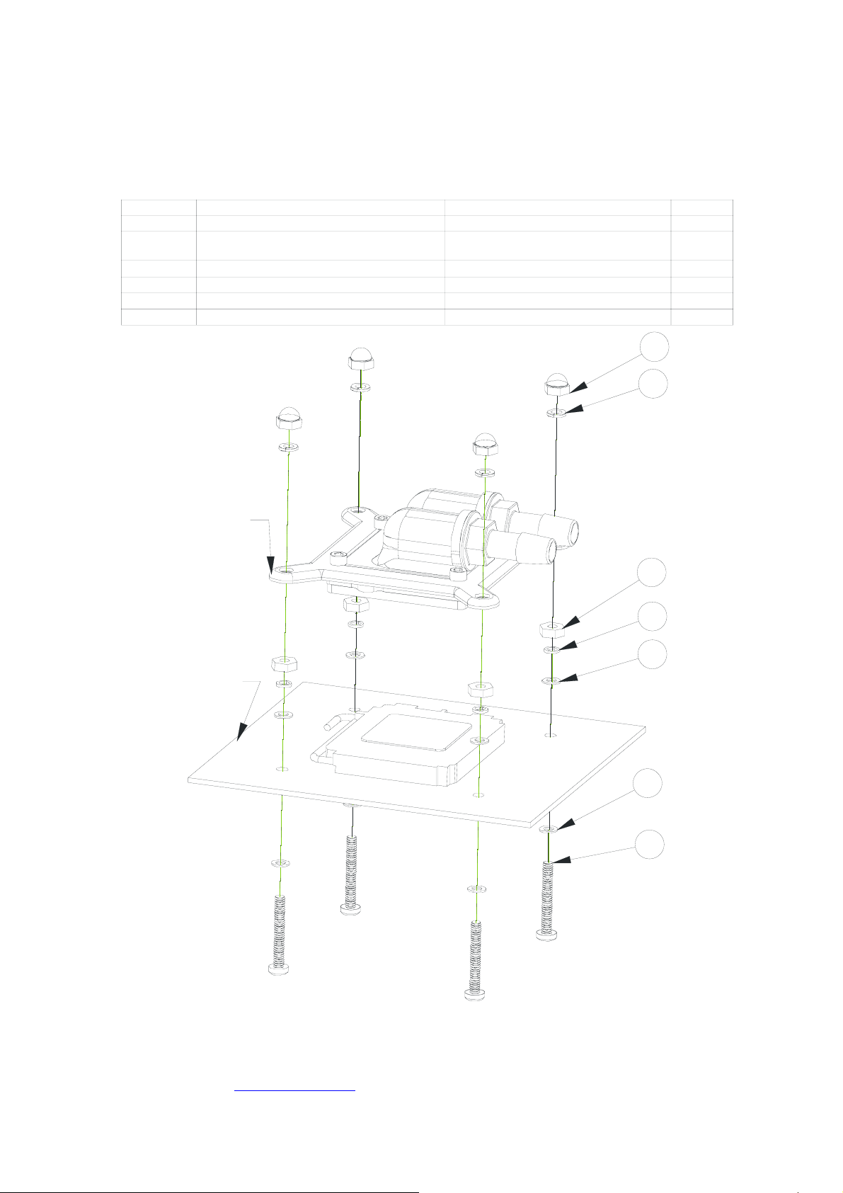
2. Installation
□ Firmly fasten the 4 posts (6-32 x 1” Philips screw Item #5) to the motherboard with the provided hardware.
□ Install the water-block assembly by fastening the provided Acorns nuts and washers in a cross pattern.
□ Note of caution: do not mix Item 2 Heavy-duty lock-washer #6 x 0.040 and Item 4 lock-washer #6 x 0.030. The heavy-duty lock-
washer must be used to fasten the water-block, whereas the regular lock-washer #6 x 0.030 is used with the motherboard posts.
ITEM NO. PART NUMBER DESCRIPTION QTY
1 6-32-Acorn-nut 6-32 Acorn nut 4
.
2 washer-0148x0 26 6x 0040-91007A619 Heavy duty Lock Was her #6 x 0.040 4
3 6-32-nut 6-32 nut 4
4 LOCK-WASH ER#6 #6 loc k washer x 0.030" 4
5 FW140X250X 0 215FB BLK blac k fiber washer 8
6 90272A153-6-32x1.00-philips
6-32 X 1" P hilips Screw
1
2
(Heavy Duty)
Apogee 1U
Water-block
4
Motherboard
3
4
5
5
6
Copyright Swiftech 2006 – All rights reserved – Last revision date: 5-16-06 – One or more Patents Pending
Rouchon Industries, Inc., dba Swiftech – 1703 E. 28
Swiftech@swiftnets.com – URL: http://www.swiftnets.com
th
Street, Signal Hill, CA 90755 – Tel. 562-595-8009 – Fax 562-595-8769 - E Mail:
- Information subject to change without notice
Page 3

3. Maintenance and Upgrades
A note of caution:
When disassembling the water-block, it is critical
for proper flow operations to maintain the
orientation of the housing in relation to the
orientation of the pins as shown below .
Exploded View
When upgrading the hold-down plate to the Xeon/Opteron
version, the hold-down plate can be installed in any direction so
as to change the orientation of the inlet and outlet as needed.
Simply loosen and remove the 4 screws holding the assembly
You must maintain the pin orientation in relation
to inlet/outlet orientation so that the fluid has a
clear and direct path between the inlet and the
outlet.
together, and replace the Hold-down plate. Firmly fasten the 4
socket screws in a cross pattern with the provided 7/64 Hex
Key. Torque value is not to exceed 16 in/lbs.
IMPORTANT DISCLOSURES
While all efforts have been made to provide the most comprehensive tutorial possible, Swiftech assumes no liability expressed or implied for any damage(s) occurring to your components
as a result of using Swiftech cooling products, either due to mistake or omission on our part in the enclosed instructions, or due to failure or defect in the Swiftech cooling products.
WARRANTY Our products are guaranteed for 12 months from the date of delivery to the final user against defects in materials or workmanship. During this period, they will be repaired or
have parts replaced provided that: (I) the product is returned to the agent from which it was purchased; (II) the product has been purchased by the end user and not used for hire purposes;
(III) the product has not been misused, handled carelessly, or other than in accordance with any instructions provided with respect to its use. This guarantee does not confer rights other
than those expressly set out above and does not cover any claims for consequential loss or damage. This guarantee is offered as an extra benefit and does not affect your statutory rights
as a consumer.
Copyright Swiftech 2006 – All rights reserved – Last revision date: 5-16-06 – One or more Patents Pending
Rouchon Industries, Inc., dba Swiftech – 1703 E. 28
Swiftech@swiftnets.com – URL: http://www.swiftnets.com
th
Street, Signal Hill, CA 90755 – Tel. 562-595-8009 – Fax 562-595-8769 - E Mail:
- Information subject to change without notice
 Loading...