

Page 1

These instructions are updated on a regular basis. Please visit our web site at
http://www.swiftnets.com
Copyright Swiftech 2006 – All rights reserved – Last revision date: 08-30-06 - Information subject to change without notice – URL: http://www.swiftnets.com
Rouchon Industries, Inc., dba Swiftech – 3700 Industry Avenue, Suite 104, Lakewood, CA 90712 – Toll free (US): 866-857-9438 – Fax 562-595-8769 - E Mail: Swiftech@swiftnets.com
PAGE 1 of 36
Page 2

Packing List
QTY ITEM
APOGEE CPU water-block, including hold-down plates (multi
1
sockets + AM2), various processors mounting systems, and (2)
½” hose clamps
MCW60 VGA water-block, including hold-down plate and
1
mounting hardware, and (2) ½” hose clamps
Pack of 8 MC14 VGA Ramsinks
1
MCW30 Chipset water-block, including hold-down plat es and
1
mounting hardware, and (2) ½” hose clamps
MCP655 pump, including mounting hardware and (2) ½” hose
1
clamps
MCRES-Micro, including mounting hardware, ½” hose-barb
1
fittings, and (2) ½” hose clamps + mounting hardware for
bracketry installation: 1 “L” bracket, 2 “U” brackets, Philips
screws, 3 teeth washers, 5 zinc plate washers
MCR220 Radiator assembly, including (2) pre-installed 120mm
1
fans with fan guards, mounting hardware, ½” black nylon hose
barb fittings, (2) 12v to 7v adapters, (2) 12v to 5v 3-pin to 4-pin
Molex adapters, and (2) ½” hose clamps, and Pre-installed MCB120 Radbox, with mounting hardware
8 Feet 7/16” industrial grade PVC tubing
Length (40”) Smartcoils 625 clear
1
1 2 Oz. Bottle of HydrX concentrated coolant
Syringe of Arctic Céramique thermal compound
1
Copyright Swiftech 2006 – All rights reserved – Last revision date: 08-30-06 - Information subject to change without notice – URL: http://www.swiftnets.com
Rouchon Industries, Inc., dba Swiftech – 3700 Industry Avenue, Suite 104, Lakewood, CA 90712 – Toll free (US): 866-857-9438 – Fax 562-595-8769 - E Mail: Swiftech@swiftnets.com
PAGE 2 of 36
Page 3

TTAABBLLEE OOFF CCOONNTTEENNTTSS
PLANNING.................................................................................................................... ......................................5
I.
1. General Guidelines.............................................................................. ................................................................5
2. Tube Routing.................................................................................... .... .... .... ... .... .... .... .........................................5
II. INSTALLATION OF THE COOLING COMPONENTS.......................................................................................6
1. MCR220 Radiator installation.............................................................................................................................7
Installation.....................................................................................................................................................7
2. APOGEE Water-block installation............................................................................................................... .....10
Intel® Pentium® 4 Socket 478............................................... ... .... .... .... .... ... .... ........ ... .... .... .... ....................12
Intel® Pentium® 4 and Pentium® D Socket LGA 775................................................................................13
Intel® Xeon™ Socket 603/604400 and 533 MHz FSB motherboards........................................................14
Intel® Xeon™ Socket 604 “Nocona” 800 MHz FSB motherboards....................................................... .... .15
AMD® Athlon®, Duron®, MP, XP, Sempron® Socket 462 ........................................................................16
AMD® 64, Sempron®, Opteron® Socket 754, 939, 940............................................................................17
AMD® 64, FX, X2, Sempron®, SocketAM2.………………………………………………………..…………..17
MCW30 Chipset cooler installation..................................................................................................................20
3.
AMD Motherboards installation: See schematic on the next page. Removal of the motherboard is
necessary to install the mountings posts....................................................................................... ....................20
Installation with Intel compatible motherboards..........................................................................................22
4. Re-installing the motherboard................................................................................... .......................................22
5. MCW60 VGA WATER-BLOCK INSTALLATION......................................... ............................................. .........23
Common installation steps.......................................................................................... ................................23
Installation with ATI Radeon (2 mounting holes)........................................................................................25
Installation with nVidia GeForce 6800 to 7900 series & ATI X1800 and above (four mounting holes)......26
Installation of the MC14 BGA Ramsinks.....................................................................................................27
6. Pump installation...............................................................................................................................................27
General Use................................................................................................................................................28
Physical installation........................................................................... ..........................................................28
Pump operating precautions:.......................... .... ....... .... .... .... ... .... .... .... ... ........ .... .... ... .... .... .... ....................28
Permanent installation to the chassis, and exploded view .........................................................................28
7. Preparing the tubing..........................................................................................................................................30
8. MCRES-Micro reservoir Installation ................................................................................................................31
Installation...................................................................................................................................................31
Preparing the coolant......................................................... .... ... .... .... ....... .... .... .... .... ... .... ............................32
Re-installing your power-supply......................................... .... ... .... .... .... .... ... .... .... ....... .... .... .... .. ..................33
Filling-up the circuit.....................................................................................................................................33
9. Troubleshooting.................................................................................................................................................35
10. Draining the system ..........................................................................................................................................35
11. Periodic Maintenance........................................................................................................................................35
12. Optional Components .......................................................................................................................................35
Copyright Swiftech 2006 – All rights reserved – Last revision date: 08-30-06 - Information subject to change without notice – URL: http://www.swiftnets.com
Rouchon Industries, Inc., dba Swiftech – 3700 Industry Avenue, Suite 104, Lakewood, CA 90712 – Toll free (US): 866-857-9438 – Fax 562-595-8769 - E Mail: Swiftech@swiftnets.com
PAGE 3 of 36
Page 4

Copyright Swiftech 2006 – All rights reserved – Last revision date: 08-30-06 - Information subject to change without notice – URL: http://www.swiftnets.com
Rouchon Industries, Inc., dba Swiftech – 3700 Industry Avenue, Suite 104, Lakewood, CA 90712 – Toll free (US): 866-857-9438 – Fax 562-595-8769 - E Mail: Swiftech@swiftnets.com
PAGE 4 of 36
Page 5

INTRODUCTION
Congratulations on your purchase of a Swiftech™ H20-220 APEX “Ultra Plus” liquid cooling system!
This kit has been designed to facilitate the installation of the components with a minimum of case modifications. While all
attempts have been made to make the installation of this system user friendly, please note that this system is intended for
users that are well versed in installing computer components.
While all efforts have been made to provide the most comprehen sive tutorial possible, Swiftech assumes no liability expressed or implied for any
damage(s) occurring to your components as a result of using Swiftech cooling products, either due to mistake or omission on our part in the above
instructions, or due to failure or defect in the Swiftech™ cooling products.
In addition, Swiftech assumes no liability, expressed or implied, for the use of this product, and more specifically for any, and all damages caused by
the use of this product to any other device in a personal computer, whether due to product failure, leak, electrical short, and or electro-magnetic
emissions.
Our products are guaranteed for 12 months from the date of delivery to the final user against defects in materials or workmanship. During this period,
they will be repaired or have parts replaced provided that: (I) the product is returned to the agent from which it was purchased; (II) the product has
been purchased by the end user and not used for hire purposes; (III) the product has not been misused, handled carelessly, or other than in
accordance with any instructions provided with respect to its use. This guarantee does not confer rights other than those expressly set out above and
does not cover any claims for consequential loss or damage. This guarantee is offered as an extra benefit and does not affect your st atutory rights as
a consumer.
DISCLAIMER
WARRANTY
I. Planning
1. GENERAL GUIDELINES
Please read this guide carefully and entirely before you start this installation. Plan your installation ahead. Observe the relative
position of the components for possible interference with other components.
Never work with electricity connected to the computer while work is in progress.
Because some work is necessary that will require cutting holes in the case, it is strongly recommended to remove all the
components from the case prior to begin with this installation.
After the metal work has been completed, carefully clean the case to remove all metal debris.
Once the time has come to re-install the motherboard and complete the liquid-cooling circuit, the motherboard should be
disconnected from the power-supply at all times during the entire mock-up phase of the installation. In case of a spill or leak on the
motherboard, do not panic! As long as the motherboard is not electrically connected, no harm is done. You must however
thoroughly dry the exposed area, using a hair dryer for example, and wait a minimum of 6 to 8 hours prior to re-connecting the
motherboard to its power source.
The reservoir should preferably be installed at the highest point of the cooling circuit (top 5 ¼” tray), although this is not absolutely
necessary if all the other components are self-purging.
Think about the airflow inside your chassis. In liquid-cooling environments, it is always better to draw fresh air from the outside
through the radiator, as opposed to using the warm air from inside the computer.
Make sure to dry-fit all components before making final connections and filling the water-cooling system.
2. TUBE ROUTING
Copyright Swiftech 2006 – All rights reserved – Last revision date: 08-30-06 - Information subject to change without notice – URL: http://www.swiftnets.com
Rouchon Industries, Inc., dba Swiftech – 3700 Industry Avenue, Suite 104, Lakewood, CA 90712 – Toll free (US): 866-857-9438 – Fax 562-595-8769 - E Mail: Swiftech@swiftnets.com
The tubing for the water-cooling system must be routed to form a complete loop that includes all elements of the system. When
daisy-chaining components, the simplest and most natural route is usually the best. Always avoid sharp bends that would kink the
tubing!
The following table contains examples on how to establish connections between the different elements of a cooling circuit based on
multiple possible configurations. These are guidelines only, and may change depending on the relative position of the components
PAGE 5 of 36
Page 6

inside your chassis.
From a performance standpoint there is very little performance to be gained from strictly controlling the component sequence: the
maximum delta T (difference in temperature) between any two points of the liquid cooling circuit does not exceed 1ºC. Whenever
possible, performance oriented users will typically want to route the radiator discharge(s) tube(s) to the inlet of the CPU cooler, since
the fluid exiting the radiators is always the coolest.
Devices: (1) CPU cooler + (1) VGA Cooler + (1) chipset Cooler + (1) Radiator + Pump-reservoir assembly
Connect: Reservoir discharge to pump inlet – MANDATORY!
Devices: (1) CPU cooler + (2) VGA Coolers + (1) chipset Cooler + (1) Radiator + Pump-reservoir assembly
Connect: Reservoir discharge to pump inlet – MANDATORY!
Devices: Dual CPU cooler and VGA cooler (SLI) configurations
Connect: CPU coolers in series: CPU cooler (1) discharge to CPU cooler (2) inlet
Devices: Dual Radiators: A second radiator can be added anywhere in the loop in series with the other components,
Connect Reservoir discharge to pump inlet – MANDATORY!
Pump discharge to chipset cooler inlet
Chipset cooler discharge to VGA cooler inlet
VGA cooler discharge to radiator inlet
Radiator discharge to CPU cooler inlet
CPU cooler discharge to reservoir inlet
Pump discharge to chipset cooler inlet
Chipset cooler discharge to VGA (1) cooler inlet
VGA (1) cooler discharge to VGA (2) cooler inlet
VGA (2) cooler discharge to radiator inlet
Radiator discharge to CPU cooler inlet
CPU cooler discharge to reservoir inlet
VGA coolers in series: VGA cooler (1) discharge to VGA cooler (2) inlet
for example
Pump discharge to radiator (1) inlet
Radiator (1) discharge to VGA cooler inlet
VGA Cooler discharge to chipset cooler inlet
Chipset cooler discharge to radiator (2) inlet
Radiator (2) discharge to CPU cooler inlet
CPU cooler discharge to reservoir inlet
II. Installation of the cooling components
Warning! Placement of the cooling components may vary depending on your chassis and motherboard configurations. A mock-up
installation is thus necessary to estimate the length of the different sections of tubing tha t will be required between each component.
The following is the recommended sequence of components installation.
1. Radiator and fan
2. Water-block(s)
• Apogee water-block
• MCW30 Chipset water-block
• MCW60 VGA water-block
3. Pump
4. Reservoir
Copyright Swiftech 2006 – All rights reserved – Last revision date: 08-30-06 - Information subject to change without notice – URL: http://www.swiftnets.com
Rouchon Industries, Inc., dba Swiftech – 3700 Industry Avenue, Suite 104, Lakewood, CA 90712 – Toll free (US): 866-857-9438 – Fax 562-595-8769 - E Mail: Swiftech@swiftnets.com
PAGE 6 of 36
Page 7

1. MCR220 RADIATOR INSTALLATION
Preamble:
The MCR220™ dual 120mm radiator ships with the fans and the Radbox chassis already pre-assembled to the radiator. It is assumed in effect that
users will take advantage of our Radbox concept (external radiator installation) due to the benefits it provides and ease of installation. In such context,
the following installation guide describes this type of installation. We also recognize that due to various considerations (cosmetics, space, or simply
user preference) a number of users will wish to install the MR220 radiator internally. Because of the large size of the radiator, it is most likely that an
internal installation will require extensive modifications in most computer cases. Because these modifications depend on the structure and dimensions
of each individual chassis, we simply cannot provide precise installation instructions to this effect. Here are some general guidelines that advanced
“case-modders” should take into consideration:
Radiator installation, general considerations:
For optimum performance radiators require an unobstructed source of cool air. This dictates either an external mounting or one on/in the case where
the radiator will draw cool air from the exterior. The second consideration is the placement of the inlet and outlet connections; at least one connection
should be at the ‘top’ of the radiator to make it self-purging.
An external mounting can be effectuated by means of the RadBox affixed to the backside of the case and the tubing routed through holes drilled in the
case underneath the power-supply. This locates the connections at the top of the radiator and it will preclude the accumulation of air in the radiator.
Single 120mm fan radiators can be mounted over appropriately sized openings in a variety of cases; conversely, mounting a dual 120mm radiator is
considerably more difficult and generally results in placing the radiator ‘inverted’ at the top, or ‘right side up’ at the bottom. Note that the ‘inverted’
mounting places the inlet and outlet facing down; this mounting will accumulate air over time. Placing the radiator ‘right side up’ in the case bottom will
make the radiator self-purging, but it will gather dust VERY quickly if adjacent to the floor. In any case, mounting a dual 120mm radiator inside a case
will require some extensive case modifications for the air inlet.
Recommended Installation
Place the radiator/radbox assembly on the back of the computer to roughly estimate where it will fit best.
You need to consider the following clearance issues:
Securing the base plate at the desired location.
¾ Exit cables and connectors from various PCI devices: the Radbox base plate can be moved in both vertical and horizontal
directions to allow clearance for the cables
¾ Opening the side panel once the Radbox is installed: the Radbox is supplied with various nylon spacers to separate the
base plate from the surface of the back-panel and to provide clearance for opening of the side-panel.
¾ Note that a chassis with 80mm fan opening(s) is likely to provide a very good range of adjustments. Conversely, a chassis
featuring a single 120mm fan opening the base-plate is a direct bolt on, but offers no adjustments, which may or may not
suit our installation for the purpose of positioning the radiator. In that case, it will be become necessary to drill (4) mounting
holes of 0.150” (~3.5mm) in diameter to install the base plate at the desired location.
Copyright Swiftech 2006 – All rights reserved – Last revision date: 08-30-06 - Information subject to change without notice – URL: http://www.swiftnets.com
Rouchon Industries, Inc., dba Swiftech – 3700 Industry Avenue, Suite 104, Lakewood, CA 90712 – Toll free (US): 866-857-9438 – Fax 562-595-8769 - E Mail: Swiftech@swiftnets.com
PAGE 7 of 36
Page 8

TIP: In the package of assorted hardware coming with your Radbox,
locate the 4 little nylon retaining washers looking like this:
to the computer back-panel. This will hold the screws in place while you
Use these to secure the screws and nylon spacers
adjust the Radbox back-plate.
Once satisfied with the position, bolt down the Radbox
back-plate with the provided nylon nuts.
Next, you will need to mark the location of the holes that
must be drilled to allow routing of the tubes through the
computer back-panel. You can cut two small pieces of the
provided PVC tubing and install these to the radiator hose
barbs, then temporarily mount the radiator assembly onto
the back-plate. The tubing will provide a convenient way
to mark the position of the holes as shown below:
Once the two holes are cut, de-burr the edges, and install the
grommets.
Install your radiator assembly onto the back plate.
Once the tubes are connected to the radiator,
the final results will look like so:
Remove the radiator assembly from the back-plate and
mark the center of the circle.
Two rubber grommets are provided with your kit so that
you can route the tube though the case without damaging
the tubing with the sharp edges of the hole. The required
hole diameter for the grommet is 7/8” (23mm).
To cut the holes, use a heavy-duty Bimetal hole saw of
7/8” in diameter:
Finally, you need to route the fan wires through the back-
panel. This can be done easily with the provided PCI adapter
plate featuring a hole and grommet for protection of the wire.
Copyright Swiftech 2006 – All rights reserved – Last revision date: 08-30-06 - Information subject to change without notice – URL: http://www.swiftnets.com
Rouchon Industries, Inc., dba Swiftech – 3700 Industry Avenue, Suite 104, Lakewood, CA 90712 – Toll free (US): 866-857-9438 – Fax 562-595-8769 - E Mail: Swiftech@swiftnets.com
Your MCR220 Radiator is now installed!
PAGE 8 of 36
Page 9

Copyright Swiftech 2006 – All rights reserved – Last revision date: 08-30-06 - Information subject to change without notice – URL: http://www.swiftnets.com
Rouchon Industries, Inc., dba Swiftech – 3700 Industry Avenue, Suite 104, Lakewood, CA 90712 – Toll free (US): 866-857-9438 – Fax 562-595-8769 - E Mail: Swiftech@swiftnets.com
PAGE 9 of 36
Page 10

2. APOGEE WATER-BLOCK INSTALLATION
This product is intended for expert users. Please consult with a qualified technician for installation. Improper installation may result in
damage to your components. Swiftech™ assumes no liability whatsoever, expressed or implied, for the use of these products, nor their
installation. The following instructions are subject to change without notice. Please visit our web site at www.swiftnets.com
One or more Patents pending
for updates.
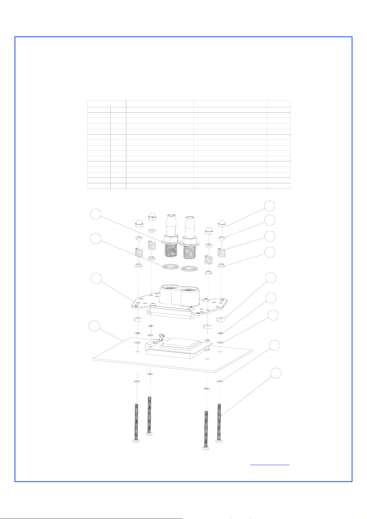
Figure 1 – Exploded View
Processor compatibility
Intel®
Pentium® 4, D, Celeron
Xeon™ (socket 603 and 604)
AMD®
Athlon XP, MP, Duron, Sempron, socket 462
Athlon 64, Sempron, Socket 754
Opteron, socket 939, 940
Socket 478
Socket 775
400 & 533 MHz FSB
800 MHz FSB (Nocona)
Copyright Swiftech 2006 – All rights reserved – Last revision date: 08-30-06 - Information subject to change without notice – URL: http://www.swiftnets.com
Rouchon Industries, Inc., dba Swiftech – 3700 Industry Avenue, Suite 104, Lakewood, CA 90712 – Toll free (US): 866-857-9438 – Fax 562-595-8769 - E Mail:
Swiftech@swiftnets.com
PAGE 10 of 36
Page 11

Packing List
COMPONENT ID COMPONENT DESCRIPTION QTY USAGE
BHSC006C0-007SS 6-32 X 7/16 BUT HD CAP SS 4.00 WATER-BLOCK ASSEMBLY
O-RING 3/32 B1000-133 O-RING 3/32 X 1 13/1 1.00 WATER-BLOCK ASSEMBLY
APOGEE-H APOGEE WATERBLOCK HOUSING 1.00 WATER-BLOCK ASSEMBLY
APOGEE-BRKT APOGEE HOLD-DOWN PLATE 1.00 WATER-BLOCK ASSEMBLY
APOGEE-BP APOGEE BASE PLATE 1.00 WATER-BLOCK ASSEMBLY
B1000-2.5X50 BUNA-N 70D BLACK O-RING 2.00 FITTINGS
PM4S-6BN 1/4" - 1/8 NPSM TO 3/8" ID 2.00 FITTINGS
PM4S-8BN 1/4" - 1/8 NPSM TO 1/2 ID 2.00 FITTINGS
22HC04688 15/32" HOSE CLAMP 2.00 FITTINGS
22HC0672B 43/64" PREMIUM HOSE CLAMP 2.00 FITTINGS
SPRING6 SPRING FOR MCW6000-775 4.00 COMMON HARDWARE
6-32 HEX CAP 6-32 ACRON NUT 4.00 COMMON HARDWARE
12SWS0444 NYLON SHOULDER WASHER 8.00 COMMON HARDWARE
LOCKWASHER6 LOCK WASHER #6 6.00 COMMON HARDWARE
FW140X250X0215FB BLK BLACK FIBER WASHER .140X.250X. 10.00 COMMON HARDWARE
632.112PHPMS 6X32 X 1 1/2 PHILIPS PAN HEAD 4.00 COMMON HARDWARE
6-32 NUT 6-32 NUT 4.00 COMMON HARDWARE
6-32 X 1 5/8 6-32 X 1 5/8 4.00 XEON SCREWS
WASHER-0148X0266X0040-91007A619 LOCK WASHER #6 X 0.040 4.00 AMD SOCKET 754/939/940,AM2 HARDWARE
90272A153-6-32X1.00-PHILIPS SCREW 6-32 X 1” PHILIPS SCREW 4.00 AMD SOCKET 754/939/940, AM2 HARDWARE
13RS040637 ROUND SPACER 4.00 AMD SOCKET 754/939/940,AM2 HARDWARE
APOGEE-AM2-BP APOGEE AM2 BASE PLATE 1.00 AMD SOCKET AM2 HARDWARE
ARCTIC CÉRAMIQUE ARCTIC CÉRAMIQUE 1.00 THERMAL COMPOUND
Common installation guidelines
1. Step-by step
2. Individual installation schematics
The provided mounting hardware is common to Intel® Pentium® 4 socket 478, socket LGA775, and AMD® socket 462. AMD® socket
754, 939, 940 & AM2 mounting hardware is identified in a separate pack, as well as Intel® Xeon hardware.
Removal of the motherboard is necessary to install the mounting posts in all cases, except for AMD® socket 754,
939, 940 and AM2.
The Apogee water-block may be installed in any direction. Simply rotate the water-block in your hand prior to fasten it
to the processor when you are filling up the circuit. This will purge it from any air bubbles.
The inlet and outlet are interchangeable with respect to flow direction.
Coolant: use of distilled water is mandatory. Swiftech’s HydrX coolant is recommended as an antifungal, and
corrosion inhibitor.
Install the fittings with their o-rings into the water block. Tighten each fitting until the flange of the fitting mates with
the ledge of the water-block, then lock it by adding ¼ to ½ turn.
Remove the existing heat sink from your motherboard.
Apply the provided Arctic Céramique thermal compound to the CPU following the comprehensive installation
instructions provided here: http://www.arcticsilver.com/ceramique_instructions.htm
Install the Apogee water-block following the individual installation schematics for each type of CPU socket provided
hereafter.
Connect the tubing to the water-block hose-barbs. Use the provided hose-clamps to secure the tubing to the barbs.
Copyright Swiftech 2006 – All rights reserved – Last revision date: 08-30-06 - Information subject to change without notice – URL: http://www.swiftnets.com
Rouchon Industries, Inc., dba Swiftech – 3700 Industry Avenue, Suite 104, Lakewood, CA 90712 – Toll free (US): 866-857-9438 – Fax 562-595-8769 - E Mail:
Swiftech@swiftnets.com
PAGE 11 of 36
Page 12

Intel® Pentium® 4 Socket 478
ITEM NO. PART NUMBER DESCRIPTION QTY.
1S478
2 apogee-assy 1
3 APOGEE-P4S478--HARDWARE 4 x
Intel® Pentium® 4
Socket 478
Use hardware from the “common pack”
Intel Pe ntium 4 socke t 4 78
motherboard and processor
APOGEE-H Housing 1
APOGEE-BP Base Plate 1
APOGEE-BRCKT Universal hold-down plate 1
O-RING-9557K473
2a
1-4-straightx3-8-barb
2b
3a 6-32-Acorn-nut 6-32 Acorn nut 1
3b 70927-368 Spring 1
6-32-nut 6-32 nut 1
3c
LOCK-WASHER#6 #6 lock washer 1
3d
FW140X250X0215FB BLK black fiber washer 2
3e
91772A157-6-32x1.5 6-32 x 1 1/2" philips screw 1
3f
12SWS0444
3g
2b
2a
1-4'" NPSM barb fitting O-Ring 2
1/4" NPSM X 3/8" Barb fitting 2
NYLON SHOULDER WASHER 2
1
3a
3g
3b
3g
2
3c
3d
3e
3e
1
3f
Copyright Swiftech 2006 – All rights reserved – Last revision date: 08-30-06 - Information subject to change without notice – URL: http://www.swiftnets.com
Rouchon Industries, Inc., dba Swiftech – 3700 Industry Avenue, Suite 104, Lakewood, CA 90712 – Toll free (US): 866-857-9438 – Fax 562-595-8769 - E Mail:
Swiftech@swiftnets.com
PAGE 12 of 36
Page 13

Intel® Pentium® 4 and Pentium® D
Socket LGA 775
Intel® Pentium® 4 and Pentium® D Socket LGA 775
Use hardware from the “common pack”
ITEM NO. PART NUMBER DESCRIPTION QTY.
1 LPGA 775 Motherboard 1
2 apogee-assy 1
92949A149 4
O-RING-9557K473 1-4'" NPSM barb fitting O-Ring 2
2a 1-4-straightx3-8-barb 1/4" NPSM X 3/8" Barb fitting 2
2b O-RING_3-32 B1000-133 O-RING 3/3 2 X 1 13/1 1
APOGEE-H
APOGEE-BP
APOGEE-BRCKT
3
APOGEE-775-HARDWARE
6-32-Acorn-nut
3a
SPRING6
3b
6-32-nut
3c
LOCK-WASHER#6
3d
3e FW140X250X0215FB BLK black fiber washer 2
3f 91772A157-6-32x1.5 Philips screw 6-32 x 1 1/2 1
3g 12SWS0444 NYLON SHOULDER WASHER 1
Housing 1
Base Plate 1
Universal hold-dow n plate 1
4 x
Acorn nut 1
spring 1
6-32 nut 1
Lock washer 1
2b
2a
3a
3g
3b
2
3c
1
3d
3e
3e
3f
Copyright Swiftech 2006 – All rights reserved – Last revision date: 08-30-06 - Information subject to change without notice – URL: http://www.swiftnets.com
Rouchon Industries, Inc., dba Swiftech – 3700 Industry Avenue, Suite 104, Lakewood, CA 90712 – Toll free (US): 866-857-9438 – Fax 562-595-8769 - E Mail:
Swiftech@swiftnets.com
PAGE 13 of 36
Page 14
Intel® Xeon™ Socket 603/604
400 and 533 MHz FSB motherboards
Intel® Xeon™ Socket 603/604400 and 533 MHz FSB motherboards
Use all parts from “common parts pack” except Philips screws: replace with the enclosed
6-32 1 5/8” long screws, instead of the 1 1/2” long screws supplied in the common parts pack.
ITEM NO. PART NUMBER DESCRIPTION QTY.
1 Socket-603-604 Motherboard 1
2apogee-assy 1
3 APOGEE-XEON-HARDWARE
2b
APOGEE-H Housing 1
APOGEE-BP Base Plate 1
APOGEE-BRCKT
2a O-RING-9557K473 1-4'" NPSM barb fitting O-Ring 2
2b 1-4-straightx3-8-barb 1/4" NPSM X 3/8" Barb fitting 2
3a 6-32-Acorn-nut 6-32 Acorn nut 1
3b SPRING6
3c 6-32-nut 6-32 nut 1
LOCK-WASHER#6 #6 lock washer 1
3d
3e FW140X250X0215FB BLK black fiber washer 2
3f 6-32X1.5-8 6-32 x 1 5/8" phi lips screw 1
12SWS0444
3g
Universal hold-dow n plate 1
Spring
NYLON SHOULD ER W ASH ER 2
3a
3g
4 x
1
2a
1
3b
3g
2
3c
3d
3e
3e
33f
Copyright Swiftech 2006 – All rights reserved – Last revision date: 08-30-06 - Information subject to change without notice – URL: http://www.swiftnets.com
Rouchon Industries, Inc., dba Swiftech – 3700 Industry Avenue, Suite 104, Lakewood, CA 90712 – Toll free (US): 866-857-9438 – Fax 562-595-8769 - E Mail:
Swiftech@swiftnets.com
PAGE 14 of 36
Page 15

Intel® Xeon™ Socket 604 “Nocona”
800 MHz FSB motherboards
Intel® Xeon™ Socket 604 “Nocona” 800 MHz FSB motherboards
Use Intel Xeon “Nocona” separate hardware.
ITEM NO. PART NUMBER DESCRIPTION Q TY.
1
2
3 chassis 1
4
5
6 90272A153-6-32x1-philips
7 apogee-assy 1
7b
Nocona board mockup
spring-backplate
3a STANDOFF-0.187 4
4-40 nylon retaining washer
SPACER-13LTS2501400697
APOGEE-H Housing 1
APOGEE-BP
APOGEE-BRCKT Universal hold-down plate 1
O-RING-9557K473 1-4'" NPSM barb fitting O-Ring 2
7a
1-4-straightx3-8-barb 1/4" NPSM X 3/8" Barb fitting 2
7b
Motherboard
retention spring (provided by
motherboard vendors)
4-40 nylon retaining washer 4
Apogee - Nocona nylon
spacer
6-32 x 1" Philips zinc plated
screw
Base Plate 1
1
1
4
4
7a
6
7
5
4
1
2
3a
3
Note to dual processor users: since the Apex Ultra is provided with one Waterblock only, you will need to procure another Apogee
Waterblock separately for your second.
Copyright Swiftech 2006 – All rights reserved – Last revision date: 08-30-06 - Information subject to change without notice – URL: http://www.swiftnets.com
Rouchon Industries, Inc., dba Swiftech – 3700 Industry Avenue, Suite 104, Lakewood, CA 90712 – Toll free (US): 866-857-9438 – Fax 562-595-8769 - E Mail:
Swiftech@swiftnets.com
PAGE 15 of 36
Page 16

AMD® Athlon®, Duron®, MP, XP,
Sempron® Socket 462
AMD® Athlon®, Duron®, MP, XP, Sempron® Socket 462
Use common hard ware p a ck .
Compatibility: Exclusively compatible with motherboards featuring
mounting holes around the socket.
ITEM NO. PART NUMBER DESC RIPTION QTY.
1
2
3 APOGEE-462-HARDWARE
socket462
apogee-assy Waterblock 1
92949A149 6-32 X 3/8" PHILIPS 4
O-RING-9557K473
2a
2b 1-4-straightx3-8-barb 1/4" NPSM X 3/8" Barb fitting 2
APOGEE-H Housing 1
APOGEE-BP Base Plate 1
APOGEE-BRCKT
3a 6-32-Acorn-nut Acorn n ut 1
3b
SPRING6
3c 6-32-nut Hex Nut 1
3d LOCK-WASHER#6 Lock washer 1
3e FW140X250X0215FB BLK Ffiber washer 2
91772A157-6-32x1.5
3f
3g 12SWS0444 Nylon shou lde r washer 1
2b
Motherboard and CPU assy. 1
1-4'" NPSM barb fitting O-Ring 2
Universal hold-down plat e 1
4 x
Spring 1
6-32 x 1 1/2 philips screw 1
3a
2a
3g
3b
2
3c
3d
3e
1
3e
3f
«An additional part is available in order to work with motherboards with high density of capacitors around the socket". Article #AP-S462-R
Copyright Swiftech 2006 – All rights reserved – Last revision date: 08-30-06 - Information subject to change without notice – URL: http://www.swiftnets.com
Rouchon Industries, Inc., dba Swiftech – 3700 Industry Avenue, Suite 104, Lakewood, CA 90712 – Toll free (US): 866-857-9438 – Fax 562-595-8769 - E Mail:
Swiftech@swiftnets.com
PAGE 16 of 36
Page 17

AMD® 64, Sempron®, Opteron®
Socket 754, 939, 940
AMD® 64, Sempron®, Opteron® Socket 754, 939, 940
Use separate AMD 754/939/940 hardware pack
ITEM NO. PART NUMBER DESCRIPT ION QTY
1 90272A153-6-32x1.00-philips 6-32 x 1" Philips screw 2
2
3 13RS040637 Nylon spacer for Apogee K8 assy 2
4 AJ00264
5 1-4-NPSMx3-8-barb 1/4" NPSM X 3/8" Barb fitting 2
6 O-RING-9557K473 1-4'" NPSM barb fitting O-Ring 2
washer-0148x0266x0040-91007A619 Lock Washer #6 x 0.040 2
Motherboard Back plate (not provided)
5
1
.
1
CPU Water-block
Assy .
Motherboard
6
2
3
4
Copyright Swiftech 2006 – All rights reserved – Last revision date: 08-30-06 - Information subject to change without notice – URL: http://www.swiftnets.com
Rouchon Industries, Inc., dba Swiftech – 3700 Industry Avenue, Suite 104, Lakewood, CA 90712 – Toll free (US): 866-857-9438 – Fax 562-595-8769 - E Mail:
Swiftech@swiftnets.com
PAGE 17 of 36
Page 18

AMD® 64, FX, X2, Sempron®,
Socket AM2
Remove the pre-installed hold-down plate first, as described on the next page.
ITEM
1 90272A153-6-32x1.00-philips Philips screw 4
2 washer- 01 48x 026 6x 0 040-91007A619 Lock Washer #6 x 0.040 4
3 apogee-assy-AM2 1
4 13RS040637
5 SOCKET AM2 1
PART NUMBER DESCRIPTION QTY
Nylon spac er for Apogee
K8 assy
.
4
1
2
3
4
5
Copyright Swiftech 2006 – All rights reserved – Last revision date: 08-30-06 - Information subject to change without notice – URL: http://www.swiftnets.com
Rouchon Industries, Inc., dba Swiftech – 3700 Industry Avenue, Suite 104, Lakewood, CA 90712 – Toll free (US): 866-857-9438 – Fax 562-595-8769 - E Mail:
Swiftech@swiftnets.com
PAGE 18 of 36
Page 19

The Apogee water-block ships pre-installed with the multi-socket hold-down plate. In order to install your Apogee with AMD’s AM2
socket, you will need to remove the existing hold-down plate and replace it with the AM2 model as follows:
Step 1: loosen all 4 screws using the included hex key, and set
aside the standard hold-down plate.
Step 2: place the AM2 hold-down plate on the Apogee body, and
fasten all four screws in cross pattern.
You can now use your Apogee with AM2 socket. Please read the common and step by step installation guidelines in page 2 to proceed
with the installation of the product.
Copyright Swiftech 2006 – All rights reserved – Last revision date: 08-30-06 - Information subject to change without notice – URL: http://www.swiftnets.com
Rouchon Industries, Inc., dba Swiftech – 3700 Industry Avenue, Suite 104, Lakewood, CA 90712 – Toll free (US): 866-857-9438 – Fax 562-595-8769 - E Mail:
Swiftech@swiftnets.com
PAGE 19 of 36
Page 20

3. MCW30 CHIPSET COOLER INSTALLATION
Preamble
The MCW30 is shipped pre-assembled for installation with AMD compatible motherboards. If you own an AMD compatible motherboard,
simply follow the steps listed below. If you own an Intel compatible motherboard you can either leave the AMD brackets providing that
they do not interfere with components on your motherboard, or you can remove them. If you do remove the brackets, please use the
provided 4-40 x 5/16” socket screws to reassemble the water-block.
Motherboard compatibility list: Please refer to our list of known compatible motherboards on the MCW30 product page at:
http://www.swiftnets.com
Intel and AMD common installation steps
• The MCW30 chipset water-block may be installed in any direction. Simply rotate the water-block in your hand prior to fasten it to the
processor when you are filling up the circuit. This will purge it from any air bubbles.
• The inlet and outlet are interchangeable with respect to flow direction.
Assembly
• Install the fittings with their o-rings into the water block and tighten each fitting until the flange of the fitting mates with the ledge of
the water-block o-ring groove, then lock it by adding ¼ to ½ turn.
• Remove the existing heat sink from your motherboard.
• Apply the provided Arctic Céramique thermal compound to the CPU following the comprehensive installation instructions provided
here: http://www.arcticsilver.com/ceramique_instructions.htm
• Install the Mcw30 water-block following the individual installation schematic for each type of CPU socket provided hereafter.
Intel setup
AMD setup
AMD Motherboards installation: See schematic on the next page. Removal of the motherboard is
necessary to install the mountings posts
• Remove the existing heatsink
• Install the two mounting posts 11 as shown in the schematic and fasten them with the nuts 13 and washes 14.
• Clean off the CPU with a degreaser, and spread some of the included thermal compound over it
• Install the MCW30 on the chip.
• Install the springs 9, tension limiters 10, and knurled knobs 12
• Gradually and alternatively fasten the knobs until the proper tension is reached: an equal amount of tension is provided by the
tension limiters. Do not overtighten the knobs!
• Installation is now complete.
Copyright Swiftech 2006 – All rights reserved – Last revision date: 08-30-06 - Information subject to change without notice – URL: http://www.swiftnets.com
Rouchon Industries, Inc., dba Swiftech – 3700 Industry Avenue, Suite 104, Lakewood, CA 90712 – Toll free (US): 866-857-9438 – Fax 562-595-8769 - E Mail:
Swiftech@swiftnets.com
PAGE 20 of 36
Page 21

ITEM
1 MCW30-base-plate 1
2 MCW30-HOUSING 1
3 92196A109 4-40 x 7/ 16" S /S socket s c r ew 4
4 1-4-NPSMx3-8-barb 1/4" NPSM X 3/8" Barb fitting 2
5 O-RING-9557K473 1-4'" NP S M bar b fitting O-Ring 2
7 board-mockup 1
8 MCW30-bracket2 2
9 70700S spring 2
10 SCREW INSULATOR10SC004025 2
11 4-40x1-25-philips-91400A124 4-40 x 1.25 philips s cr ew 2
12 KNURLED NUT 0800440TN 2
13 4-40-nut 2
14 4-40-fiberwasher 4
PART NUMBER DESCRIPTION QTY
4
.
5
12
10
2
9
3
8
1
13
14
14
7
11
Copyright Swiftech 2006 – All rights reserved – Last revision date: 08-30-06 - Information subject to change without notice – URL: http://www.swiftnets.com
Rouchon Industries, Inc., dba Swiftech – 3700 Industry Avenue, Suite 104, Lakewood, CA 90712 – Toll free (US): 866-857-9438 – Fax 562-595-8769 - E Mail:
Swiftech@swiftnets.com
PAGE 21 of 36
Page 22

Installation with Intel compatible motherboards
You can either leave the AMD brackets providing that they do not interfere with components on your motherboard, or you can remove
them. If you do remove the brackets, please use the provided 4-40 x 5/16” socket screws to reassemble the water-block.
Removal of the motherboard is NOT necessary to install the MCW30 in this configuration.
• Remove the existing heatsink
• Clean off the CPU with a degreaser, and spread some of the included thermal compound over it.
• Install the MCW30 over the CPU
• Insert the hooks of the wire clips 7 underneath the loops of the motherboard.
• Installation is now complete
4. RE-INSTALLING THE MOTHERBOARD
Now that the APOGEE and MCW30 water-blocks are securely fastened to the motherboard, go-ahead and install the motherboard into
the chassis, following the instructions provided in your motherboard installation guide.
Copyright Swiftech 2006 – All rights reserved – Last revision date: 08-30-06 - Information subject to change without notice – URL: http://www.swiftnets.com
Rouchon Industries, Inc., dba Swiftech – 3700 Industry Avenue, Suite 104, Lakewood, CA 90712 – Toll free (US): 866-857-9438 – Fax 562-595-8769 - E Mail:
Swiftech@swiftnets.com
PAGE 22 of 36
Page 23

5. MCW60 VGA WATER-BLOCK INSTALLATION
Overview
The MCW60 is shipped with a pre-assembled hold-down plate compatible with all nVidia High-end GeForce and ATI Radeon using a
four-hole fastening system. Mid-range ATI products using a 2-hole bolt-down are also compatible by using the included haldware. Please
refer to our product page for further information.
4-holes setup
2-holes setup
1/ ATI 2-hole bolt-down ONLY: pre-installation steps
You will need to remove the chrome hold-down plate as shown below, before you can install the product with ATI 2-hole boards. Once
done, please follow the steps common to all VGA adapters, and the installation schematic provided page 2.
Remove all four screws with the provided Hex key and set aside
the chrome hold-down plate, as it will not be needed.
Re-install the four screws, using the provided lock-washers. Your
water-block is now ready to use with ATI 2-hole bolt pattern.
Common installation steps to all graphics cards: General information
• The MCW60 VGA water-block may be installed in any direction.
• The inlet and outlet are interchangeable with respect to flow direction.
BEFORE INSTALLATION
• Install the barb fittings with their o-rings into the water block before you fasten the water-block to the VGA card
• Tighten each fitting until the flange of the fitting mates with the ledge of the water-block o-ring groove, then lock it by
adding ¼ to ½ turn.
• Remove the existing heat sink from your graphics card, and carefully clean off the GPU with an electronics degreaser.
Copyright Swiftech 2006 – All rights reserved – Last revision date: 08-30-06 - Information subject to change without notice – URL: http://www.swiftnets.com
Rouchon Industries, Inc., dba Swiftech – 3700 Industry Avenue, Suite 104, Lakewood, CA 90712 – Toll free (US): 866-857-9438 – Fax 562-595-8769 - E Mail:
Swiftech@swiftnets.com
PAGE 23 of 36
Page 24

• Apply the provided Arctic Céramique thermal compound to the CPU following the comprehensive installation instructions
provided here: http://www.arcticsilver.com/ceramique_instructions.htm
• Install the MCW60 water-block following the individual installation schematic for the type of GPU setup correponding to your
VGA adapter and provided hereafter.
AFTER INSTALLATION
• Connect the tubing to the water-block hose-barbs. Use the provided hose-clamps to secure the tubing to
the barbs. Always test your setup extensively for leaks before you energize the graphics card.
Copyright Swiftech 2006 – All rights reserved – Last revision date: 08-30-06 - Information subject to change without notice – URL: http://www.swiftnets.com
Rouchon Industries, Inc., dba Swiftech – 3700 Industry Avenue, Suite 104, Lakewood, CA 90712 – Toll free (US): 866-857-9438 – Fax 562-595-8769 - E Mail:
Swiftech@swiftnets.com
PAGE 24 of 36
Page 25

Installation with ATI Radeon (2 mounting holes)
ITEM
1 mcw60-housing-rev2 1
2
3 O-RING_3-32 Body o-ring 1
4
5 O-RING-9557K473 1-4'" NPSM barb fitting O-Ring 2
6 92196A146 6-32 x 5/8 socket screw
7 stiffening-bar 1
8 4-40x1-25-phili ps-91400A124 4-40 x 1.25 philips screw 2
9
10 X800-XT 1
11
12 4-40-acorn-nut Nylon Nut 4-40 - 0500440CN 2
13 washer-240x140x0038 2
14
15 LOCK-WASHER#6 #6 lock washer x 0.030" 4
16 MCW60-HDP-R2 WCW60 HOLD-DOWN PLATE R2
MCW60 BASE PLATE 1
1-4-NPSMx3-8-barb
70700S
13ME028
SCREW INSULATOR10SC004025 2
PART NUMBER
DESCRIPTION
1/4" NPSM X 3/8" Barb fitting
spring
Nylon metric flat washer
12
14
9
QTY
.
2
4
2
2
1
17 - Discard
13
6
15
5
1
3
2
11
7
8
· Remove the existing heatsink
· Clean off the GPU with a degreaser, and spread some of the included thermal compound over it.
· Install the MCW60 onto the GPU
· Install screws #8, back-plate #7 and nylon spacers #11 thru the circuit board and the MCW60 water-block.
· Install washers #13, springs #9, compression limiter #9 and acorn nut #12, then gradually and alternatively fasten acorn nuts
(#12) until they bottom out.
· Installation of the water-block is now complete.
Copyright Swiftech 2006 – All rights reserved – Last revision date: 08-30-06 - Information subject to change without notice – URL: http://www.swiftnets.com
Rouchon Industries, Inc., dba Swiftech – 3700 Industry Avenue, Suite 104, Lakewood, CA 90712 – Toll free (US): 866-857-9438 – Fax 562-595-8769 - E Mail:
Swiftech@swiftnets.com
PAGE 25 of 36
Page 26

Installation with nVidia GeForce 6800 to 7900 series & ATI X1800 and above (four mounting holes)
ITEM NO. PA RT NUMBER DESCRIPTION QTY
1 MCW60 WATER-BLOCK 1
2 1-4-NPSMx3-8-barb 1/4" NPSM X 3/8" Barb fitting 2
3 M CW60-HDP-R2 MCW60 HOLD-DOWN PLATE R2 1
4 MCW60-CB-R2 MCW60 CROSS-BRACKET R2 1
5 M CW60-2-56-PFH-CS 2-56 CUSTOM SCREW 4
6 REFERENCE VGA ADAPTER 1
.
1
2
· Remove the existing heatsink
· Clean off the GPU with a degreaser, and spread some of the included thermal compound over it.
· Position the MCW60 over the GPU, aligning the 4 feet of the hold-down plate to the circuit board thru-holes
· Insert screws #5 thru cross-bracket #4, thru the circuit board, and fasten them into the legs of hold-down plate #3,
tightening the screws gradually and in a cross pattern.
· Installation of the water-block is now complete
3
6
4
5
Copyright Swiftech 2006 – All rights reserved – Last revision date: 08-30-06 - Information subject to change without notice – URL: http://www.swiftnets.com
Rouchon Industries, Inc., dba Swiftech – 3700 Industry Avenue, Suite 104, Lakewood, CA 90712 – Toll free (US): 866-857-9438 – Fax 562-595-8769 - E Mail:
Swiftech@swiftnets.com
PAGE 26 of 36
Page 27

Installation of the MC14 BGA Ramsinks
Common steps:
1. Remove the existing memory heatsink
2. Carefully clean-off the BGA modules with an electronics degreaser
Plug-and-play installation
1. Peel-off the protection paper from the MC14 Ramsink
2. Firmly press the Ramsink onto the BGA module for 5 to 10 seconds. Installation is complete. Please check the "installation issues"
note below before you install the two Ramsinks located directly below the inlet and outlet barb fittings of the MCW60 water-block.
Advanced Installation
For a superior mechanical joint and enhanced thermal conductivity, the MC14 Ramsinks may be permanently attached to the memory
modules using a thermally conductive epoxy glue such as Arctic Alumina or Arctic Ceramique Epoxy. Non electrically conductive or noncapacitive glue should be used to prevent damage to the memory, thus precluding the use of Arctic Silver Epoxy which is capacitive.
Please refer to http://www.arcticsilver.com for installation guidelines.
Please note again that such installation is permanent and will void your Warranty
1. Peel-off the protection paper from the MC14 Ramsink, and carefully clean off the thermal adhesive with a solvent
2. Carefully clean-off the BGA modules with an electronics degreaser
3. Apply a small amount of epoxy glue to the memory modules.
3. Gently rub the MC14 ramsink on the BGA module in a circular motion in order to spread the epoxy evenly
4. Allow the epoxy to dry following manufacturer instructions.Installation is complete.
Installation issues
Problem: In some instances, there may not be sufficient clearance to install the Ramsinks on the memory modules located directly under
the water-block inlet and outlet.
Solution: Double-checking clearance and remedy
You will need to install a piece of tubing on each of the MCW60 fittings. To do so, we recommend that you rub some liquid soap on the
barb fittings with the tip of your finger. This will ease installation as well as removal of the tubing later on. Then place an MC14 Ramsink
underneath the fitting and onto the memory module (without removing the peel-off tape at first). If there is not enough clerance you can
remedy the problem simply by cutting the pins of the Ramsinks to the appropriate length with a small pair of pliers as shown below:
Shortening the MC14 pins for additional clearance Installation complete!
Now that you water-blocks are installed, let us move on to the installation of the pump.
6. PUMP INSTALLATION
Copyright Swiftech 2006 – All rights reserved – Last revision date: 08-30-06 - Information subject to change without notice – URL: http://www.swiftnets.com
Rouchon Industries, Inc., dba Swiftech – 3700 Industry Avenue, Suite 104, Lakewood, CA 90712 – Toll free (US): 866-857-9438 – Fax 562-595-8769 - E Mail:
Swiftech@swiftnets.com
PAGE 27 of 36
Page 28

General Use
The MCP655 pump is a magnetically driven
centrifugal pump featuring a 12 V DC motor. It
requires no maintenance when used with demineralized water and the appropriate anti-fungal
additives. We recommend using 5% Swiftech’s
HydrX™ as an additive. The pump is designed to be
connected to your computer power supply using the
standard Molex 4 pin connectors.
The MCP655 pump is neither submersible, nor selfpriming. The inlet needs to be continuously
supplied with fluid for the pump to operate properly.
Physical installation
Determine the best location for your pump by
observing how the tubing will be routed to the
rest of the circuit. Sharp bends in the tubing
should always be avoided to prevent kinks,
which will reduce or completely prevent flow of
the cooling fluid.
In general, we recommend installation of the
pump at the bottom of the chassis.
The base of the pump features a soft
neoprene pad coated with strong adhesive
material. Once the final location for the pump
has been determined, simply peel-off the
pad’s protective paper, and press the pump
against the chassis surface. The surface
should be clean, and non greasy. Thru-bolts
are also provided for permanent installation,
and require drilling holes in the chassis.
The back of the pump features a
potentiometer to allow users to vary the pump
speed from 1800 to 4800 rpm. Full speed is
suggested for maximum performance. When
reducing the pump speed, the operating noise
will also decrease proportionally, but so will
the performance. A flow rate chart is provided
below
Erreur !
Pump operating
precautions:
The MCP655 pump should never be run dry,
even for a quick test. You should always prime
Note 1: Always make sure to directly connect the RESERVOIR DISCHARGE to
the PUMP INLET.
Note 2: Please read important preamble in paragraph 5 below “Preparing the
Tubing” prior to installing the tubing to your pump.
the pump with fluid before you start operating it
(see warranty note *).
Use of coloring die or fluorescent additives
containing particulate fillers will cause excessive
wear to the pump’s impeller bearing (see warranty
note **).
Permanent installation to the chassis, and exploded view
Copyright Swiftech 2006 – All rights reserved – Last revision date: 08-30-06 - Information subject to change without notice – URL: http://www.swiftnets.com
Rouchon Industries, Inc., dba Swiftech – 3700 Industry Avenue, Suite 104, Lakewood, CA 90712 – Toll free (US): 866-857-9438 – Fax 562-595-8769 - E Mail:
Swiftech@swiftnets.com
PAGE 28 of 36
Page 29

Specifications:
Nominal voltage / Connector 12 V DC / Molex 4 pin Maximum pressure 50 PSI (3.5 BAR)
Operating voltage range 8 to 24 VDC Maximum head 10 ft (3.1 m)
Nominal current (@ 12 V) 2 amps Maximum discharge ~ 317 GPH (1200 LPH)
Nominal power (@ 12 V) 24 W Temperature range 32 °F to 140°F (0 °C to 60 °C)
Motor type Brushless, microprocessor controlled Weight 1.4 LB (650 gr.)
Impeller Housing material Noryl® Connection size ½" barbs
Copyright Swiftech 2006 – All rights reserved – Last revision date: 08-30-06 - Information subject to change without notice – URL: http://www.swiftnets.com
Rouchon Industries, Inc., dba Swiftech – 3700 Industry Avenue, Suite 104, Lakewood, CA 90712 – Toll free (US): 866-857-9438 – Fax 562-595-8769 - E Mail:
Swiftech@swiftnets.com
PAGE 29 of 36
Page 30

7. PREPARING THE TUBING
Preamble:
Your kit comes with 7/16” ID (5/8” OD) tubing. This type of tubing
was specifically selected following suggestions made by our
enthusiast users because it offers very low flow restriction, similar to
that of true ½” ID tubing, without the bulk of true ½” (which is ¾” OD
and therefore hard to work with). This tubing will fit easily onto
standard ½” barbs EXCEPT for the MCP655 pump. In effect, the
design of the hose barbs on this pump makes it quite difficult to install
this slightly smaller tubing. Two things can be done to ease this
process:
• Rub the pump barbs with liquid soap to make them slippery
• Soften-up the extremity of the tubes by dipping them in a
glass of boiling water for about 20 to 30 seconds (boil
some water in a microwave oven, then dip the extremity of
the tube).
Then work the tube around the pump hose barbs by pushing it firmly.
Be patient, it is not easy but it does work.
Smartcoils and tubing installation
Now that your radiator, water-blocks and pump are in place, it is time
to cut segments of tubing and connect the devices together.
Your kit comes with a 40” length of Smartcoils which, when extended
is a sufficient length to cover 6 feet of tubing. Use of these coils is
recommended whenever there is a sharp bending radius in order to
prevent kinking and flattening of the tube over time.
Gather the Smartcoils towards the center of the tubing, and then
pull on the ends of the tubing. This will allow the coils to expand
to their natural pitch.
Another technique to evenly spread the coils along the tubing
consists in pushing one of the extremities of the coil clockwise.
This will loosen the coils from around the tube, and allow you to
spread them easily.
Tight radii sections require that coils be close to each other (1/8”
spacing coil to coil). In straight sections, coils can be spaced up
to ¼” or more, coil-to-coil.
Then, with one end of a tube connected to a startup
component such as the water-block for example, roughly
estimate the length that you will need to the next
component, and cut the tube and coil squarely with a pair of
scissors. Work your way through the entire circuit in the
same fashion, until you are satisfied with the tube routing.
Secure all the connections of tube to hose barbs with the
provided hose-clamps:
Example of wrapping for a tight bend. (shown with the blue version
for picture clarity – The kit actually comes with clear coils).
Wrap the Smartcoils around the tubing
Copyright Swiftech 2006 – All rights reserved – Last revision date: 08-30-06 - Information subject to change without notice – URL: http://www.swiftnets.com
Rouchon Industries, Inc., dba Swiftech – 3700 Industry Avenue, Suite 104, Lakewood, CA 90712 – Toll free (US): 866-857-9438 – Fax 562-595-8769 - E Mail:
Swiftech@swiftnets.com
PAGE 30 of 36
Page 31

8. MCRES-MICRO RESERVOIR INSTALLATION
ITEM
NO.
PART NUMBER DESCRIPTION QTY.
1 MCRES-MICRO Reservoir 1
2
1-4“ NPSM x 3-8“ and 1-2“barb
Barb fitting
3 O-RING-9557K473 Barb fitting O-Ring 2
4 pg7-o-ring
Fill-cap o-ring
5 pg7-plug Pg7 Fill-cap 1
6 MOUNTING HARDWARE 3
6a
6b
6c
6d
90272A152-6-32x0500philips 6-32 x 7/8" (22mm) Philips screw 1
90760A007
washer-91007A614
6-32 Nut 1
Lock Washer
WASHER-RUBBER-437X150X092 Rubber Washer 1
7 panel 1
2 pairs
each
1
1
Figure 1
Installation
• The MCRES-MICRO can be installed in any suitable location meeting its form factor requirements. For filling and
bleeding purposes, it is preferable to hold or to install the MCRES-MICRO at the highest point of the liquid cooling
loop. However, once filled and hermetically closed, the reservoir can be installed practically anywhere as long as it is
kept upright as shown in figure 1. Also, to facilitate the filling and bleeding operations, you might want to wait until the
circuit has been filled-up before you fasten the reservoir permanently to the chassis.
Copyright Swiftech 2006 – All rights reserved – Last revision date: 08-30-06 - Information subject to change without notice – URL: http://www.swiftnets.com
Rouchon Industries, Inc., dba Swiftech – 3700 Industry Avenue, Suite 104, Lakewood, CA 90712 – Toll free (US): 866-857-9438 – Fax 562-595-8769 - E Mail:
Swiftech@swiftnets.com
PAGE 31 of 36
Page 32

• Fastening the device to the case: two mounting methods can be used
¾ Permanent mount with the provided mounting hardware as shown in figure 1. Three holes will need to be
¾ Easy mount, with the provided Velcro strips. This is a fairly secure mount, as we use extra strong Velcro.
• The only critical precaution to take when installing the reservoir is to make sure that the discharge line is
directly connected to the inlet of the pump. In other words, the pump (inlet) should be the first device connected
to the reservoir discharge. Using a different routing will make the filling and bleeding of the circuit difficult, and may
prevent the pump to prime properly.
• Once you have found a suitable location for the reservoir, go ahead and connect the tubing to the reservoir fittings,
then secure them with the provided hose clamps.
Preparing the coolant
• Your kit comes with a 2 Oz (60ml) bottle of Swiftech’s specially formulated HydrX™ concentrated coolant. The
product should be mixed with distilled water only
plastic bottle, and complete filling with distilled water. Your coolant is now ready. Note: a 5% mix might still allow
some algae formation over prolonged usage if your system is continuously exposed to daylight (such as a clear
acrylic case for example). Under such circumstances, we would suggest using a 10% mix.
• Use of alcohols (Alcohol Allyl, Amyl, Benzyl, Ethyl (Ethanol), Isopropyl, Methyl (Methanol), n-Bu tyl) or
antifreeze products containing the listed alcohols is prohibited as it will result in deterioration of the
reservoir over-time, and will void your warranty. Resistance to Ethylene and Methylene glycol used in antifreeze
products is excellent.
• Minimum Operating Level is situated at the Swiftech Logo (approximately ½” of the reservoir). The reservoir should
not be operated below this level, which could result in degradation of the system cooling.
drilled for a permanent mount. Simply use the reservoir as a template to mark the hole locations, and use a
0.150” (4mm) drill bit to drill the holes. Make sure to clean up any metal shavings from the case once you are
done.
However, if your computer is to travel often (LAN parties for example), a permanent mount remains more suited
for a more reliable fastening of the device.
. Simply empty the concentrated coolant into a 33 fl oz (1 liter)
Copyright Swiftech 2006 – All rights reserved – Last revision date: 08-30-06 - Information subject to change without notice – URL: http://www.swiftnets.com
Rouchon Industries, Inc., dba Swiftech – 3700 Industry Avenue, Suite 104, Lakewood, CA 90712 – Toll free (US): 866-857-9438 – Fax 562-595-8769 - E Mail:
Swiftech@swiftnets.com
PAGE 32 of 36
Page 33

MCRes Mi cro
Bracketry install ati on and
examples
6
7
4
ITEM NO. P A RT NUMBER DESCRIPTION QTY
1 BCKT1 "L" bracket 1
2 BCKT 2 "U" bracket 2
90272A146-6-32x3-8-philips
3
4 91772A158-6-32X1.75
5 90760A007 6-32 Nut w/teeth washer 3
6 FW150X437X092 Rubber Was her 43 7X 150 X 092 2
5
7 93286A041-WASHER
6-32 x 3/8” P hilips s cr ew
6-32 x 1 3/4" Philips screw
zinc plat ed was h er
3
1
.
3
2
5
Note 1: rubber w asher 6
should be inserted between
either side of the reservoir
ear and the U bracket 2.
2
7
6
2
Panel
DRI LL O NE
.150"
(3.8MM) HOLE
Reservoir ear
UPRIGHT MOUNT
4
5
HANGING MOUNT
Panel
Re-installing your power-supply
• Prior to fill-up the c ircuit, you will need to re-install your power-supply in order to start-up the pump during the fill
procedure. You must be able to start the PSU without it being connected to the motherboard. While the Internet
contains numerous references on how to use a wire or a paper-clip to short-out pin 13 and 14 of the 20 pin ATX
connector as shown below, we nonetheless recommend instead using a power-supply tester. A wide variety of these
common devices are available on the Internet (Google key word: “PSU tester”), and among Swiftech resellers
(www.frozencpu.com, www.Directron.com, www.newegg.com, etc.).
BACK-PANEL MOUNT
DRILL T WO
0.150" HOLES
2.00"(50.8mm)
Note 2: the 6-32 x 1 3/4” screw #4 & nut # 5 assembly
is designed to protrude as little as possible in order
to reduce overall clearance necessary for the Micro
Res assembly. It is thus necessary to slightly push the nut
in order to engage it on the screw thread.
APART
Panel
Copyright Swiftech 2006 – All rights reserved – Last revision date: 08-30-06 - Information subject to change without notice – URL: http://www.swiftnets.com
Rouchon Industries, Inc., dba Swiftech – 3700 Industry Avenue, Suite 104, Lakewood, CA 90712 – Toll free (US): 866-857-9438 – Fax 562-595-8769 - E Mail:
Swiftech@swiftnets.com
PAGE 33 of 36
Page 34

You can also visit this link for further information: http://www.directron.com/2powersupplies.html
Filling-up the circuit
• Simply pour the coolant that you prepared into the reservoir – carefully to avoid spills, allowing the circuit to fill-up
by simple gravity. Note: for the gravity to take effect the reservoir should be placed or held at the highest point of the
cooling circuit. Once the reservoir is full, seal the fill port back with its cap in order to avoid any spills, and start-up the
pump. The reservoir will quickly (within 1 second) empty itself. Immediately turn off the pump, top-off the fluid to the
maximum level, and restart the pump. You need to repeat this operation 2 to 3 times, until the circuit is finally full of
coolant. Then, allow the system to run from 10 to 30 minutes uninterrupted to clear all the micro-bubbles and foam, and
finally top-off the level one last time. Your liquid cooling circuit is now ready, and you may permanently install the
reservoir.
• Allow the system to run for (3) hours and frequently inspect all your connections for possible leaks before
you reconnect and re-install all your components (motherboard, hard drives, etc.)
CONGRATULATIONS, YOUR INSTALLATION IS NOW COMPLETE!
Example of installation
Copyright Swiftech 2006 – All rights reserved – Last revision date: 08-30-06 - Information subject to change without notice – URL: http://www.swiftnets.com
Rouchon Industries, Inc., dba Swiftech – 3700 Industry Avenue, Suite 104, Lakewood, CA 90712 – Toll free (US): 866-857-9438 – Fax 562-595-8769 - E Mail:
Swiftech@swiftnets.com
PAGE 34 of 36
Page 35
9. TROUBLESHOOTING
Air keeps circulating into the circuit, long after the pump has primed:
o There is a significant pocket of air trapped into the circuit. In most cases this will be due to the fact that the radiator
and or the water-block where installed upside down. Temporarily dismount the device and re-orient right side-up until
all the air has escaped back into the circuit.
o The fluid level is too low: top-off the reservoir to the appropriate level.
o One of the components connections is loose, or improperly tightened: Inspect each connection for traces of
moisture, and tighten all worm-drive clamps, and various connections in the circuit.
The pump does not prime.
It is likely that the circuit is not installed correctly. Please check that the reservoir discharge is duly connected to the pump inlet.
Reminder: do not let the pump run dry.
The Coolant is filled with debris of some sort:
Despite our best efforts, such as lengthy ultrasonic cleaning of the radiator, and careful inspection and cleaning of all the parts
we manufacture, it is always possible that debris or some sort may be contaminating your circuit. When this happens it will
significantly affect the performance of the APOGEE water-block, which mini-jets can be easily obstructed due to their small
size. The circuit should then be completely flushed (see draining procedure below), and the APOGEE water-block should be
disassembled for inspection and cleaning.
10. DRAINING THE SYSTEM
Open up the fill-cap from the MCRES-Micro
Then, you will need to disconnect a line from one of the lowermost components. Typically, this would be the pump. You
need to procure a bucket large enough to receive approximately 1 liter of fluid, and place the bucket underneath the
connection that you intend to “break”. Disconnect the line, and place both ends into the bucket, until all the liquid is
drained from the system.
11. PERIODIC MAINTENANCE
Every 6 months: dust off the radiator fins and fan. You can use a can of compressed air for example, available
in most electronic supply stores. If you live in a very dusty area, you should perform this task at closer intervals.
It is essential to maintain the optimum performance of your cooling system.
Inspect the liquid level inside the reservoir, and refill if necessary (no refills are normally necessary for 18
months of continuous usage). Evaporation in this closed circuit is limited but still present due to some
permeability in the vinyl lines.
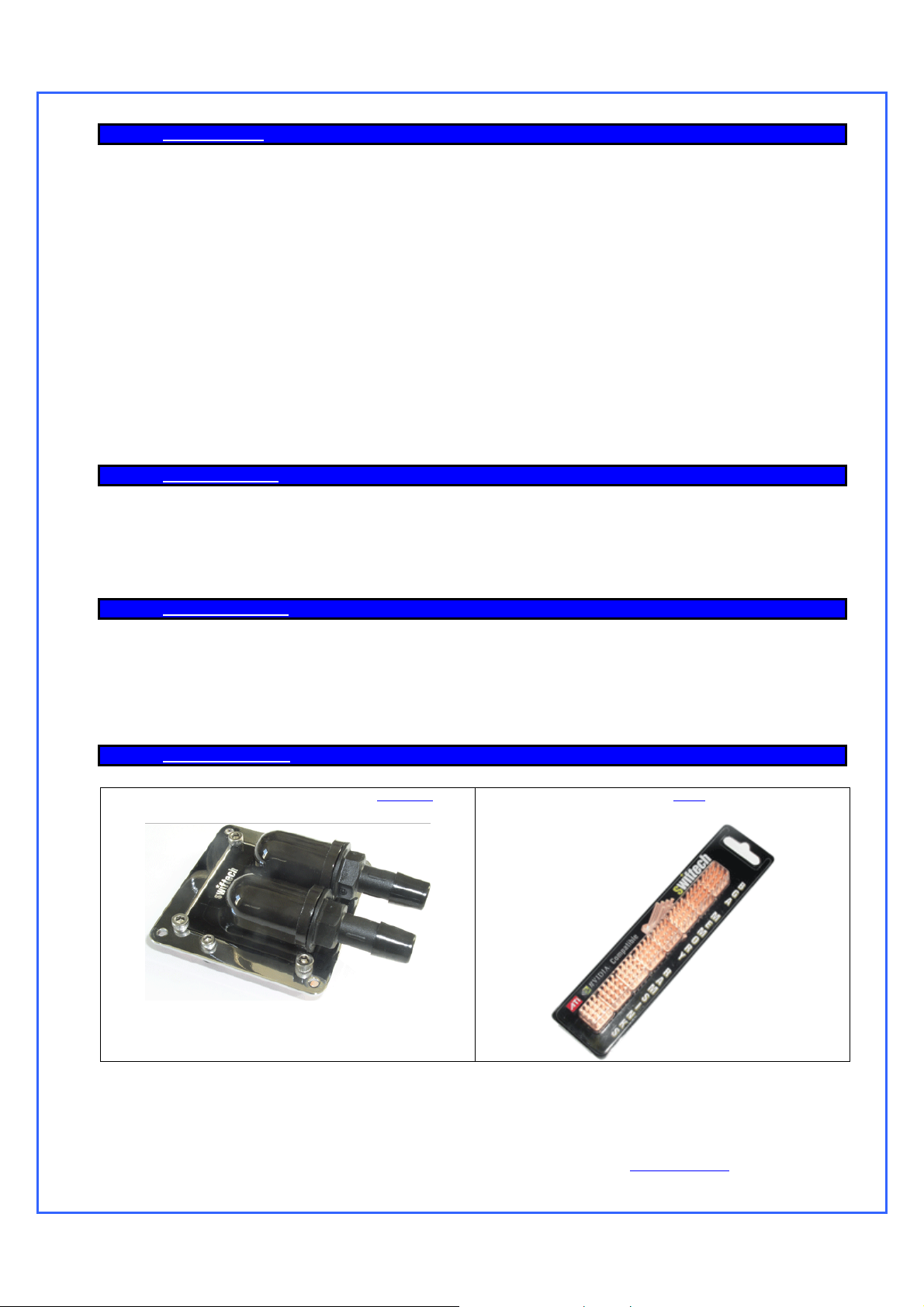
12. OPTIONAL COMPONENTS
Liquid Cool your high-end SLI VGA with a second MCW60™
Cool the graphics memory with our MC14 Ramsinks
Copyright Swiftech 2006 – All rights reserved – Last revision date: 08-30-06 - Information subject to change without notice – URL: http://www.swiftnets.com
Rouchon Industries, Inc., dba Swiftech – 3700 Industry Avenue, Suite 104, Lakewood, CA 90712 – Toll free (US): 866-857-9438 – Fax 562-595-8769 - E Mail:
Swiftech@swiftnets.com
PAGE 35 of 36
Page 36

Add a second Apogee
water block for multiprocessor applications,
such as dual AMD®, dual Xeon™, or dual Opteron™
For Dual Xeon “Nocona” users do not forget to add the optional
Nocona hardware (part AP-NC604) when you purchase your
second Apogee water-block. In effect, while this hardware is
included in this kit, it is not included when the Apogee water-block
is sold separately.
Cool the Chipset with the MCW30
Chipset cooler.
Copyright Swiftech 2006 – All rights reserved – Last revision date: 08-30-06 - Information subject to change without notice – URL: http://www.swiftnets.com
Rouchon Industries, Inc., dba Swiftech – 3700 Industry Avenue, Suite 104, Lakewood, CA 90712 – Toll free (US): 866-857-9438 – Fax 562-595-8769 - E Mail:
Swiftech@swiftnets.com
PAGE 36 of 36
 Loading...