

Page 1

H
H
2
2
0--
0
2
2
2
2
0
0
A
A
P
P
E
E
X
X
ULL
U
TII
T
M
M
A
A
“
“
X
X
T
T
”
”
pll
p
u
u
s
s
These instructions are updated on a regular basis. Please visit our web site at www.swiftech.com
Copyright Swiftech 2009 – All rights reserved – Last revision date: 10-29-08- Information subject to change without notice – URL: http://www.swiftech.com
Rouchon Industries, Inc., dba Swiftech – 151 West Victoria Street, Long Beach, CA 90803 – Tel. 310-763-0336 – Fax 310-763-7095 - E Mail: help@swiftech.com 1 of 15
Page 2
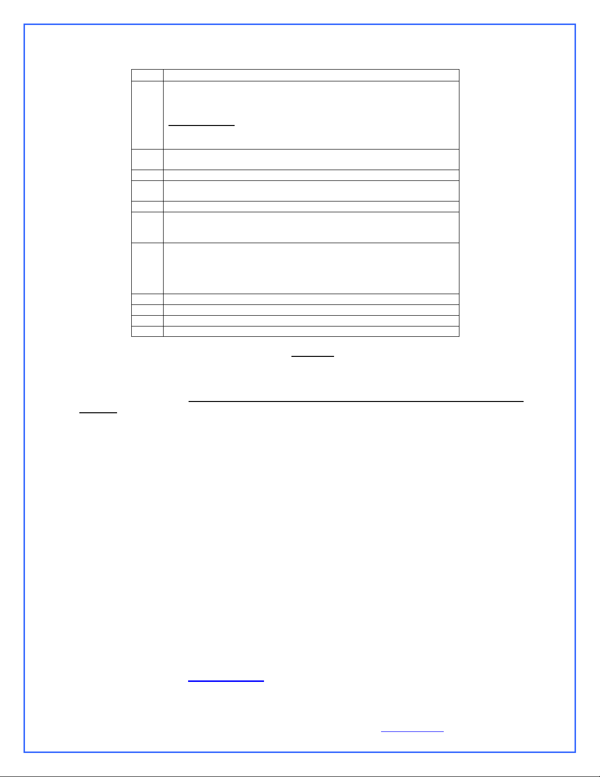
Packing List
QTY
ITEM
1
APOGEE™ XT water-block, including socket 1366, socket 1156
and socket 775 hold-down plates for all Intel Core® desktop
microprocessors.
Important note: Free Upgrade available (see terms and
conditions) for AMD® socket 754, 939, and AM2, as well as
Intel® socket 771 (Xeon series) Server form factor
1
MCW60 VGA water-block, including standard hold-down plate &
mounting hardware, GT200 adapter kit, and (2) ½” hose clamps
1
Pack of 8 MC14 VGA Ramsinks, and 4 MC21 Mosfet heatsinks
1
MCW30 Chipset water-block, including hold-down plates and mounting
hardware, and (2) ½” hose clamps
1
MCP655-B pump, including mounting hardware and (2) ½” hose clamps
1
MCRES-Micro Rev. 2, including ½” hose-barb fittings, and hose clamps,
bracketry & hardware for various installation: 1 “L” bracket, 2 “U”
brackets
1
MCR220 Radiator assembly, including (2) pre-installed 120mm fans with
fan guards, mounting hardware, ½” black nylon hose barb fittings, (2)
12v to 7v adapters, (2) 12v to 5v 3-pin to 4-pin Molex adapters, and (2)
hose clamps
And Pre-installed MCB-120 Radbox, with mounting hardware
8
Feet 7/16” industrial grade PVC tubing
1
Length (40”) Smartcoils 625 blue
1
2 Oz. Bottle of HydrX concentrated coolant
1
Syringe of Arctic Céramique thermal compound
TOLL FREE (Continental US only) 1-888-85SWIFT (1-888-857-9438)
Mailing Address
Swiftech
151 West Victoria St.
Long beach, CA 90803
USA
Telephone
310-763-0336
Fax
310-763-7095
Warning!
The Apogee™ XT water-block included with your kit is compatible with all the most popular
processors available on the market. In an effort to cut on waste however, some of the less popular
mounting mechanisms have not been physically included in the kit and are available for free on
demand. They are:
Hold-down plate for Intel® legacy server platforms (socket 603-604, and 771 for Xeon™)
Hold-down plate for AMD® socket 754, 939, F and AM2
If you own one of the above platforms, all you have to do is contact customer support and the part
will be shipped to you at no charge by express mail or equivalent. The following terms and
conditions apply:
Worldwide except Europe:
Please email within 90 days of your date of purchase (proof of purchase required), call, write or Fax
to Swiftech customer service at:
Europe: Please email rma@bacata.net within 90 days of your date of purchase (proof of purchase
required)
Copyright Swiftech 2009 – All rights reserved – Last revision date: 10-29-08- Information subject to change without notice – URL: http://www.swiftech.com
Rouchon Industries, Inc., dba Swiftech – 151 West Victoria Street, Long Beach, CA 90803 – Tel. 310-763-0336 – Fax 310-763-7095 - E Mail: help@swiftech.com 2 of 15
Page 3

TTAABBLLEE OOFF CCOONNTTEENNTTS
S
I. PLANNING ................................................................................................................................................... 4
1. General Guidelines ..................................................................................................................................... 4
2. Tube Routing ............................................................................................................................................... 4
II. INSTALLATION OF THE COOLING COMPONENTS ................................................................................ 5
1. MCR220 Radiator installation .................................................................................................................... 6
General concept schematic ............................................................................................................. 6
Installation ........................................................................................................................................ 7
2. APOGEE™ XT Water-block installation .................................................................................................... 8
3. MCW30 Chipset water-block installation.................................................................................................. 8
4. MCW60 VGA water-block installation ...................................................................................................... 8
5. Re-installing the motherboard ................................................................................................................... 8
6. Pump installation ........................................................................................................................................ 8
General Use ..................................................................................................................................... 9
Physical installation.......................................................................................................................... 9
Pump operating precautions: ........................................................................................................... 9
7. MCRES-Micro reservoir Installation ........................................................................................................ 10
Installation ...................................................................................................................................... 11
Preparing the coolant ..................................................................................................................... 12
8. Installing the tubing .................................................................................................................................. 13
9. Completing the installation ...................................................................................................................... 13
Re-installing your power-supply ..................................................................................................... 13
Filling-up the circuit ........................................................................................................................ 14
10. Troubleshooting ........................................................................................................................................ 15
11. Draining the system.................................................................................................................................. 15
12. Periodic Maintenance ............................................................................................................................... 15
13. Optional Components .............................................................................................................................. 15
Copyright Swiftech 2009 – All rights reserved – Last revision date: 10-29-08- Information subject to change without notice – URL: http://www.swiftech.com
Rouchon Industries, Inc., dba Swiftech – 151 West Victoria Street, Long Beach, CA 90803 – Tel. 310-763-0336 – Fax 310-763-7095 - E Mail: help@swiftech.com 3 of 15
Page 4

INTRODUCTION
DISCLAIMER
While all efforts have been made to provide the most comprehensive tutorial possible, Swiftech assumes no liability expressed or implied for
any damage(s) occurring to your components as a result of using Swiftech cooling products, either due to mistake or omission on our part in
the above instructions, or due to failure or defect in the Swiftech™ cooling products.
In addition, Swiftech assumes no liability, expressed or implied, for the use of this product, and more specifically for any, and all damages
caused by the use of this product to any other device in a personal computer, whether due to product failure, leak, electrical short, and or
electro-magnetic emissions.
WARRANTY
Our products are guaranteed for 12 months from the date of delivery to the final user against defects in materials or workmanship. During this
period, they will be repaired or have parts replaced provided that: (I) the product is returned to the agent from which it was purchased; (II) the
product has been purchased by the end user and not used for hire purposes; (III) the product has not been misused, handled carelessly, or
other than in accordance with any instructions provided with respect to its use. This guarantee does not confer rights other than those expressly
set out above and does not cover any claims for consequential loss or damage. This guarantee is offered as an extra benefit and does not
affect your statutory rights as a consumer.
Congratulations on your purchase of a Swiftech™ H20-APEX liquid cooling system!
This kit has been designed to facilitate the installation of the components with a minimum of case modifications.
While all attempts have been made to make the installation of this system user friendly, please note that this system
is intended for users that are well versed in installing computer components.
I. Planning
1. GENERAL GUIDELINES
Please read this guide carefully and entirely before you start this installation. Plan your installation ahead. Observe the
relative position of the components for possible interference with other components.
Never work with electricity connected to the computer while work is in progress.
Because some work is necessary that will require cutting holes in the case, it is strongly recommended to remove all the
components from the case prior to begin with this installation.
After the metal work has been completed, carefully clean the case to remove all metal debris.
Once the time has come to re-install the motherboard and complete the liquid-cooling circuit, the motherboard should be
disconnected from the power-supply at all times during the entire mock-up phase of the installation. In case of a spill or leak
on the motherboard, do not panic! As long as the motherboard is not electrically connected, no harm is done. You must
however thoroughly dry the exposed area, using a hair dryer for example, and wait a minimum of 6 to 8 hours prior to reconnecting the motherboard to its power source.
The reservoir should preferably be installed at the highest point of the cooling circuit (top 5 ¼” tray), although this is not
absolutely necessary if all the other components are self-purging.
Think about the airflow inside your chassis. In liquid-cooling environments, it is always better to draw fresh air from the
outside through the radiator, as opposed to using the warm air from inside the computer.
Make sure to dry-fit all components before making final connections and filling the water-cooling system.
2. TUBE ROUTING
The tubing for the water-cooling system must be routed to form a complete loop that includes all elements of the system.
When daisy-chaining components, the simplest and most natural route is usually the best. Always avoid sharp bends that
Copyright Swiftech 2009 – All rights reserved – Last revision date: 10-29-08- Information subject to change without notice – URL: http://www.swiftech.com
Rouchon Industries, Inc., dba Swiftech – 151 West Victoria Street, Long Beach, CA 90803 – Tel. 310-763-0336 – Fax 310-763-7095 - E Mail: help@swiftech.com 4 of 15
would kink the tubing!
The following table contains examples on how to establish connections between the different elements of a cooling circuit
based on multiple possible configurations. These are guidelines only, and may change depending on the relative position of
the components inside your chassis.
Page 5

From a performance standpoint there is very little performance to be gained from strictly controlling the component
Devices:
(1) CPU cooler + (1) Radiator + Pump-reservoir assembly
Connect:
Pump discharge to radiator inlet
Radiator discharge to CPU cooler inlet
CPU cooler discharge to reservoir inlet
Reservoir discharge to pump inlet – MANDATORY!
Alternatively,
Connect
Pump discharge to CPU cooler inlet
CPU cooler discharge to radiator inlet
Radiator discharge to reservoir inlet
Reservoir discharge to pump inlet – MANDATORY!
Devices
(1) CPU cooler + (1) VGA cooler + (1) Radiator + Pump-reservoir assembly
Connect:
Pump discharge to VGA Cooler inlet
VGA cooler discharge to radiator inlet
Radiator discharge to CPU cooler inlet
CPU cooler discharge to reservoir inlet
Reservoir discharge to pump inlet – MANDATORY!
Alternatively,
Connect:
Pump discharge to CPU cooler inlet
CPU cooler discharge to VGA cooler inlet
VGA cooler discharge to radiator inlet
Radiator discharge to reservoir inlet
Reservoir discharge to pump inlet – MANDATORY!
Devices:
(1) CPU cooler + (1) VGA Cooler + (1) chipset Cooler + (1) Radiator + Pump-reservoir assembly
Connect:
Pump discharge to chipset cooler inlet
Chipset cooler discharge to VGA cooler inlet
VGA cooler discharge to radiator inlet
Radiator discharge to CPU cooler inlet
CPU cooler discharge to reservoir inlet
Reservoir discharge to pump inlet – MANDATORY!
Alternatively,
Connect:
Pump discharge to CPU cooler inlet
CPU cooler discharge to chipset cooler inlet
Chipset cooler discharge to VGA cooler inlet
VGA cooler discharge to radiator inlet
Radiator discharge to reservoir inlet
Reservoir discharge to pump inlet – MANDATORY!
Devices:
Dual CPU cooler and VGA cooler (SLI) configurations
Connect:
CPU coolers in series: CPU cooler (1) discharge to CPU cooler (2) inlet
VGA coolers in series: VGA cooler (1) discharge to VGA cooler (2) inlet
Devices:
Dual Radiators: A second radiator can be added anywhere in the loop in series with the other components,
for example
Connect
Pump discharge to radiator (1) inlet
Radiator (1) discharge to VGA cooler inlet
VGA Cooler discharge to chipset cooler inlet
Chipset cooler discharge to radiator (2) inlet
Radiator (2) discharge to CPU cooler inlet
CPU cooler discharge to reservoir inlet
Reservoir discharge to pump inlet – MANDATORY!
sequence: the maximum delta T (difference in temperature) between any two points of the liquid cooling circuit does not
exceed 1ºC. Whenever possible, performance oriented users will typically want to route the radiator discharge(s) tube(s) to
the inlet of the CPU cooler, since the fluid exiting the radiators is always the coolest.
II. Installation of the cooling components
Warning! Placement of the cooling components may vary depending on your chassis and motherboard configurations. A mock-up
installation is thus necessary to estimate the length of the different sections of tubing that will be required between each component.
The following is the recommended sequence of components installation.
1. Radiator and fan
2. Water-block(s)
3. Pump
4. Reservoir
Copyright Swiftech 2009 – All rights reserved – Last revision date: 10-29-08- Information subject to change without notice – URL: http://www.swiftech.com
Rouchon Industries, Inc., dba Swiftech – 151 West Victoria Street, Long Beach, CA 90803 – Tel. 310-763-0336 – Fax 310-763-7095 - E Mail: help@swiftech.com 5 of 15
Page 6

1. MCR220 RADIATOR INSTALLATION
Preamble:
The MCR220 dual 120mm radiator ships with the fans and the Radbox chassis already pre-assembled to the radiator. It is assumed in effect
that users will take advantage of our Radbox concept (external radiator installation) due to the benefits it provides and ease of installation. In
such context, the following installation guide describes this type of installation. We also recognize that due to various considerations (cosmetics,
space, or simply user preference) a number of users will wish to install the MR220 radiator internally. Because of the large size of the radiator, it
is most likely that an internal installation will require extensive modifications in most computer cases. Because these modifications depend on the
structure and dimensions of each individual chassis, we simply cannot provide precise installation instructions to this effect. Here are some
general guidelines that advanced “case-modders” should take into consideration:
Radiator installation, general considerations:
For optimum performance radiators require an unobstructed source of cool air. This dictates either an external mounting or one on/in the case
where the radiator will draw cool air from the exterior. The second consideration is the placement of the inlet and outlet connections; at least one
connection should be at the „top‟ of the radiator to make it self-purging.
An external mounting can be effectuated by means of the RadBox affixed to the backside of the case and the tubing routed through holes drilled
in the case underneath the power-supply. This places the connections at the top of the radiator and it will preclude the accumulation of air in the
radiator.
Single 120mm fan radiators can be mounted over appropriately sized openings in a variety of cases; conversely, mounting a dual 120mm
radiator is considerably more difficult and generally results in placing the radiator „inverted‟ at the top, or „right side up‟ at the bottom. Note that
the „inverted‟ mounting places the inlet and outlet facing down; this mounting will accumulate air over time. Placing the radiator „right side up‟ in
the case bottom will make the radiator self-purging, but it will gather dust VERY quickly if adjacent to the floor. In many situations, mounting a
dual 120mm radiator inside a case will require extensive modifications for the air inlet and mounting of the radiator; it should be noted m that
case manufacturer growing awareness for water-cooling fosters the release of “liquid-cooling ready“ solutions that will greatly facilitate the
installation of this kit. There is no standard in this respect, and therefore no “formula” for installation; as a result users will simply need to exercise
common sense and good judgment.
General concept schematic
Copyright Swiftech 2009 – All rights reserved – Last revision date: 10-29-08- Information subject to change without notice – URL: http://www.swiftech.com
Rouchon Industries, Inc., dba Swiftech – 151 West Victoria Street, Long Beach, CA 90803 – Tel. 310-763-0336 – Fax 310-763-7095 - E Mail: help@swiftech.com 6 of 15
Page 7

Once satisfied with the position, bolt down the Radbox
back-plate with the provided nylon nuts.
Next, you will need to mark the location of the holes that
must be drilled to allow routing of the tubes through the
computer back-panel. You can cut two small pieces of the
provided PVC tubing and install these to the radiator hose
barbs, then temporarily mount the radiator assembly onto
the back-plate. The tubing will provide a convenient way
to mark the position of the holes as shown below:
Once the two holes are cut, de-burr the edges, and install the
grommets.
Install your radiator assembly onto the back plate.
Once the tubes are connected to the radiator,
the final results will look like so:
Installation
Place the radiator assembly on the back of the computer to roughly estimate where it will fit best.
You need to consider the following clearance issues:
Securing the base plate at the desired location.
Exit cables and connectors from various PCI devices: the Radbox base plate can be moved in both vertical and
horizontal directions to allow clearance for the cables
Opening the side panel once the Radbox is installed: the Radbox is supplied with various nylon spacers to separate
the base plate from the surface of the back-panel and to provide clearance for opening of the side-panel.
Note that a chassis with 80mm fan opening(s) is likely to provide a very good range of adjustments. Conversely, a
chassis featuring a single 120mm fan opening the base-plate is a direct bolt on, but offers no adjustments, which
may or may not suit our installation for the purpose of positioning the radiator. In that case, it will be become
necessary to drill (4) mounting holes of 0.150” (~3.5mm) in diameter to install the base plate at the desired location.
Copyright Swiftech 2009 – All rights reserved – Last revision date: 10-29-08- Information subject to change without notice – URL: http://www.swiftech.com
Rouchon Industries, Inc., dba Swiftech – 151 West Victoria Street, Long Beach, CA 90803 – Tel. 310-763-0336 – Fax 310-763-7095 - E Mail: help@swiftech.com 7 of 15
Page 8

Remove the radiator assembly from the back-plate and
mark the center of the circle.
Two rubber grommets are provided with your kit so that
you can route the tube though the case without damaging
the tubing with the sharp edges of the hole. The required
hole diameter for the grommet is 7/8” (23mm).
To cut the holes, use a heavy-duty Bimetal hole saw of
7/8” in diameter:
Finally, you need to route the fan wires through the back-
panel. This can be done easily with the provided PCI adapter
plate featuring a hole and grommet for protection of the wire.
2. APOGEE™ XT WATER-BLOCK INSTALLATION
Please refer to the separate installation guide inlcuded with the Apogee water-block.
3. MCW30 CHIPSET WATER-BLOCK INSTALLATION
Please refer to the separate installation guide inlcuded with the MCW30 water-block.
4. MCW60 VGA WATER-BLOCK INSTALLATION
Please refer to the separate installation guide inlcuded with the MCW60 water-block.
5. RE-INSTALLING THE MOTHERBOARD
Once your water-blocks are securely fastened to the motherboard, go-ahead and install the motherboard back into the chassis, following the
instructions provided in your motherboard installation guide.
6. PUMP INSTALLATION
Copyright Swiftech 2009 – All rights reserved – Last revision date: 10-29-08- Information subject to change without notice – URL: http://www.swiftech.com
Rouchon Industries, Inc., dba Swiftech – 151 West Victoria Street, Long Beach, CA 90803 – Tel. 310-763-0336 – Fax 310-763-7095 - E Mail: help@swiftech.com 8 of 15
Page 9

General Use
The MCP655-B pump is a magnetically driven centrifugal pump featuring a
12 V DC motor. It requires no maintenance when used with de-mineralized
water and the appropriate anti-fungal additives. We recommend using 5%
Swiftech‟s HydrX as an additive. The pump is designed to be connected
to your computer power supply using the standard Molex 4 pin connectors.
A second 3-pin connector (single blue wire) is an RPM sensor designed to
be connected to the motherboard in lieu of the CPU fan connector and the
motherboard to read the pump speed.
The MCP655-B pump is neither submersible, nor self- priming. The inlet
needs to be continuously supplied with fluid for the pump to operate
properly.
Physical installation
Determine the best location for your pump by observing how the
tubing will be routed to the rest of the circuit. Sharp bends in the tubing
should always be avoided to prevent kinks, which will reduce or
cmpletely prevent flow of the cooling fluid.
In general, we recommend installation of the pump at the bottom of
the chassis.
The base of the pump features a soft neoprene pad coated with
strong adhesive material. Once the final location for the pump has
been determined, simply peel-off the pad‟s protective paper, and press
the pump against the chassis surface. The surface should be clean,
and non greasy. Thru-bolts are also provided for permanent
installation, and require drilling holes in the chassis.
Pump operating precautions:
The MCP655-B pump should never be run dry, even for a quick test.
You should always prime the pump with fluid before you start operating it
(see warranty note *).
Use of coloring die or fluorescent additives containing particulate fillers
will cause excessive wear to the pump‟s impeller bearing (see warranty
note **).
Note 1: Always make sure to directly connect the RESERVOIR
DISCHARGE to the PUMP INLET.
Note 2: Please read important preamble in paragraph 6 below
“Preparing the Tubing” prior to installing the tubing to your pump.
Permanent installation to the chassis, and exploded view
Copyright Swiftech 2009 – All rights reserved – Last revision date: 10-29-08- Information subject to change without notice – URL: http://www.swiftech.com
Rouchon Industries, Inc., dba Swiftech – 151 West Victoria Street, Long Beach, CA 90803 – Tel. 310-763-0336 – Fax 310-763-7095 - E Mail: help@swiftech.com 9 of 15
Page 10

Nominal voltage / Connector
12 V DC / Molex 4 pin
Maximum pressure
50 PSI (3.5 BAR)
Operating voltage range
8 to 24 VDC
Maximum head
10 ft (3.1 m)
Nominal current (@ 12 V)
2 amps
Maximum discharge
~ 317 GPH (1200 LPH)
Nominal power (@ 12 V)
24 W
Temperature range
32 °F to 140°F (0 °C to 60 °C)
Motor type
Brushless, microprocessor controlled
Weight
1.4 LB (650 gr.)
Impeller Housing material
Noryl®
Connection size
½" barbs
7. MCRES-MICRO RESERVOIR INSTALLATION
Copyright Swiftech 2009 – All rights reserved – Last revision date: 10-29-08- Information subject to change without notice – URL: http://www.swiftech.com
Rouchon Industries, Inc., dba Swiftech – 151 West Victoria Street, Long Beach, CA 90803 – Tel. 310-763-0336 – Fax 310-763-7095 - E Mail: help@swiftech.com 10 of 15
Page 11

Figure 1
Port Usage definition
Upper side port: “Inlet” as shown in figure 1 is the return line from the system
Lower side port: “Outlet (to pump)” shown in figure 1 should always be connected to the pump inlet (directly if possible to facilitate filling
of the system)
The fill-port located on top of the unit is used to fill it up with coolant, and sealed with a chrome plated brass plug.
The alternate port is also sealed with a chrome plated brass plug, and can be used as:
An alternate outlet providing a straight tube routing to a pump located underneath
To feed a second pump
To plug-in a temperature sensor
A drain
Installation
The MCRES-MICRO can be installed in any suitable location meeting its form factor requirements. For filling purposes, it is preferable to
install the MCRES-MICRO at the highest point of the liquid cooling loop. However, once filled and hermetically closed, the reservoir can
be installed practically anywhere as long as it is kept upright as shown in figure 1. Also, to facilitate the filling and bleeding operations,
you might want to wait until the circuit has been filled-up before you fasten the reservoir permanently to the chassis.
Fastening the device to the case: two mounting methods can be used
Various permanent mounts thru the reservoir ears or with the provided mounting hardware as shown page 3.
Easy mount, with the provided Velcro strips. Please note that a permanent mount is recommended for a reliable fastening of the device
over time.
Copyright Swiftech 2009 – All rights reserved – Last revision date: 10-29-08- Information subject to change without notice – URL: http://www.swiftech.com
Rouchon Industries, Inc., dba Swiftech – 151 West Victoria Street, Long Beach, CA 90803 – Tel. 310-763-0336 – Fax 310-763-7095 - E Mail: help@swiftech.com 11 of 15
Page 12

ITEM NO. PART NUMBER DESCRIPTION QTY
.
1 BCKT1 "L" bracket 1
2 BCKT2 "U" bracket 2
3
90272A146-6-32x3-8-philips
3
4 91772A158-6-32X1.75
6-32 x 1 3/4" Philips screw
2
5 90760A007 6-32 Nut w/teeth washer 3
6 FW150X437X092 Rubber Washer 437X150X092 2
7 93286A041-WASHER
zinc plated washer
5
.150"
(3.8MM) HOLE
DRILL ONE
HANGING MOUNT
Panel
1
5
4
7
2
3
6
UPRIGHT MOUNT
Panel
BACK-PANEL MOUNT
Panel
2.00 " (50.8mm) APART
DRILL TWO
0.150" HOLES
6-32 x 3/8” Philips scr ew
MCRes Micro
Bracketry installation and
examples
Note 1: rubber washer 6
should be inserted between
either side of the reservoir
ear and the U bracket 2.
4
6
7
5
Reservoir ear
2
Note 2: the 6-32 x 1 3/4” screw #4 & nu t # 5 assemb ly is designed to p rotrude as little as possible in order
to reduce overall clearance necessary for the Micro Res assembly. It is thus necessary to slightly push the nut
in order to engage it on the screw thread.
Preparing the coolant
Your kit comes with a 2 Oz (60ml) bottle of Swiftech‟s specially formulated HydrX concentrated coolant. The
product should be mixed with distilled water only. Simply empty the concentrated coolant into a 33 fl oz (1 liter)
plastic bottle, and complete filling with distilled water. Your coolant is now ready. Note: a 5% mix might still allow
some algae formation over prolonged usage if your system is continuously exposed to daylight (such as a clear
acrylic case for example). Under such circumstances, we would suggest using a 10% mix.
Use of alcohols (Alcohol Allyl, Amyl, Benzyl, Ethyl (Ethanol), Isopropyl, Methyl (Methanol), n-Butyl) or
antifreeze products containing the listed alcohols is prohibited as it will result in deterioration of the
reservoir over-time, and will void your warranty. Resistance to Ethylene and Methylene glycol used in antifreeze
products is excellent.
Minimum Operating Level is situated at the Swiftech Logo (approximately ½” of the reservoir). The reservoir should
not be operated below this level, which could result in degradation of the system cooling.
Copyright Swiftech 2009 – All rights reserved – Last revision date: 10-29-08- Information subject to change without notice – URL: http://www.swiftech.com
Rouchon Industries, Inc., dba Swiftech – 151 West Victoria Street, Long Beach, CA 90803 – Tel. 310-763-0336 – Fax 310-763-7095 - E Mail: help@swiftech.com 12 of 15
Page 13

8. INSTALLING THE TUBING
Preamble:
Your kit comes with 7/16” ID (5/8” OD) tubing. This type of tubing was
specifically selected following suggestions made by our enthusiast users
because it offers very low flow restriction, similar to that of true ½” ID tubing,
without the bulk of true ½” (which is ¾” OD and therefore hard to work with).
This tubing will fit easily onto standard ½” barbs EXCEPT for the MCP655-B
pump. In effect, the design of the hose barbs on this pump makes it quite
difficult to install this slightly smaller tubing. Two things can be done to ease
this process:
Rub the pump barbs with liquid soap to make them slippery
Soften-up the extremity of the tubes by dipping them in a glass of
boiling water for about 20 to 30 seconds (boil some water in a
microwave oven, then dip the extremity of the tube).
Then work the tube around the pump hose barbs by pushing it firmly. Be
patient, it is not easy but it does work.
Smartcoils and tubing installation
Now that your radiator, water-block, pump and reservoir are in place, it is
time to cut segments of tubing and connect the devices together.
Your kit comes with a 40” length of Smartcoils which, when extended is a
sufficient length to cover 6 feet of tubing. Use of these coils is recommended
whenever there is a sharp bending radius in order to prevent kinking and
flattening of the tube over time.
Example of wrapping for a tight bend. (Shown with the blue version for
picture clarity – The kit actually comes with clear coils).
Wrap the Smartcoils around the tubing
Gather the Smartcoils towards the center of the tubing, and then
pull on the ends of the tubing. This will allow the coils to expand to
their natural pitch.
Another technique to evenly spread the coils along the tubing
consists in pushing one of the extremities of the coil clockwise.
This will loosen the coils from around the tube, and allow you to
spread them easily.
Tight radii sections require that coils be close to each other (1/8”
spacing coil to coil). In straight sections, coils can be spaced up to
¼” or more, coil-to-coil.
Then, with one end of a tube connected to a startup
component such as the water-block for example, roughly
estimate the length that you will need to the next component,
and cut the tube and coil squarely with a pair of scissors.
Work your way through the entire circuit in the same fashion,
until you are satisfied with the tube routing.
Secure all the connections of tube to hose barbs with the
provided hose-clamps:
9. COMPLETING THE INSTALLATION
Re-installing your power-supply
Copyright Swiftech 2009 – All rights reserved – Last revision date: 10-29-08- Information subject to change without notice – URL: http://www.swiftech.com
Rouchon Industries, Inc., dba Swiftech – 151 West Victoria Street, Long Beach, CA 90803 – Tel. 310-763-0336 – Fax 310-763-7095 - E Mail: help@swiftech.com 13 of 15
Page 14

Prior to fill-up the circuit, you will need to re-install your power-supply in order to start-up the pump during the fill
13
14
procedure. You must be able to start the PSU without it being connected to the motherboard. While the Internet
contains numerous references on how to use a paper-clip to short-out pin 13 and 14 of the 20 pin ATX connector as
shown below, we nonetheless recommend instead using a power-supply tester. A wide variety of these common
devices are available on the Internet (Google key word: “PSU tester”), and among Swiftech resellers
(www.frozencpu.com, www.Directron.com, www.newegg.com, etc.).
Filling-up the circuit
Simply pour the coolant that you prepared into the reservoir – carefully to avoid spills, allowing the circuit to fill-up
by simple gravity. Note: for the gravity to take effect the reservoir should be placed or held at the highest point of the
cooling circuit. Once the reservoir is full, seal the fill port back with its cap in order to avoid any spills, and start-up the
pump. The reservoir will quickly (within 1 second) empty itself. Immediately turn off the pump, top-off the fluid to the
maximum level, and restart the pump. You need to repeat this operation 2 to 3 times, until the circuit is finally full of
coolant. Then, allow the system to run 10 minutes uninterrupted to clear all the micro-bubbles and foam, and finally top-off
the level one last time. Your liquid cooling circuit is now ready, and you may permanently install the reservoir.
Allow the system to run for (3) hours and frequently inspect all your connections for possible leaks before
you reconnect and re-install all your components (motherboard, hard drives, etc.)
CONGRATULATIONS, YOUR INSTALLATION IS NOW COMPLETE!
Example of installation
Copyright Swiftech 2009 – All rights reserved – Last revision date: 10-29-08- Information subject to change without notice – URL: http://www.swiftech.com
Rouchon Industries, Inc., dba Swiftech – 151 West Victoria Street, Long Beach, CA 90803 – Tel. 310-763-0336 – Fax 310-763-7095 - E Mail: help@swiftech.com 14 of 15
Page 15

10. TROUBLESHOOTING
Air keeps circulating into the circuit, long after the pump has primed:
The pump does not prime.
The Coolant is filled with debris of some sort:
11. DRAINING THE SYSTEM
12. PERIODIC MAINTENANCE
o There is a significant pocket of air trapped into the circuit. In most cases this will be due to the fact that the radiator
and or the water-block where installed upside down. Temporarily dismount the device and re-orient right side-up until
all the air has escaped back into the circuit.
o The fluid level is too low: top-off the reservoir to the appropriate level.
o One of the components connections is loose, or improperly tightened: Inspect each connection for traces of
moisture, and tighten all worm-drive clamps, and various connections in the circuit.
It is likely that the circuit is not installed correctly. Please check that the reservoir discharge is duly connected to the pump inlet.
Reminder: do not let the pump run dry.
Despite our best efforts, such as lengthy ultrasonic cleaning of the radiator, and careful inspection and cleaning of all the parts
we manufacture, it is always possible that debris or some sort may be contaminating your circuit. When this happens it will
significantly affect the performance of the APOGEE water-block, which mini-jets can be easily obstructed due to their small
size. The circuit should then be completely flushed (see draining procedure below), and the APOGEE water-block should be
disassembled for inspection and cleaning.
Open up the fill-cap from the MCRES-Micro
Then, you will need to disconnect a line from one of the lowermost components. Typically, this would be the pump. You
need to procure a bucket large enough to receive approximately 1 liter of fluid, and place the bucket underneath the
connection that you intend to “break”. Disconnect the line, and place both ends into the bucket, until all the liquid is
drained from the system.
Every 6 months: dust off the radiator fins and fan. You can use a can of compressed air for example, available
in most electronic supply stores. If you live in a very dusty area, you should perform this task at closer intervals.
It is essential to maintain the optimum performance of your cooling system.
Inspect the liquid level inside the reservoir, and refill if necessary (no refills are normally necessary for 18
months of continuous usage). Evaporation in this closed circuit is extremely limited, but still present due to
some permeability in the vinyl lines.
13. OPTIONAL COMPONENTS
Please visit our web site at www.swiftech.com on a regular basis, as we continuously release new products that could enhance the use
of your H20-220 Apex Ultima liquid cooling kit!
Thank you for trusting Swiftech® for your computer-cooling needs!
Copyright Swiftech 2009 – All rights reserved – Last revision date: 10-29-08- Information subject to change without notice – URL: http://www.swiftech.com
Rouchon Industries, Inc., dba Swiftech – 151 West Victoria Street, Long Beach, CA 90803 – Tel. 310-763-0336 – Fax 310-763-7095 - E Mail: help@swiftech.com 15 of 15
 Loading...