

Page 1
EC800 Power Control System
1 Introduction
This section of the handbook will guide you through the operation of the electrical system. All details are correct
at the time of going to press. Please also see the online version which will include any later updates or
amendments.
Further technical details are contained in section 3 or in the supporting technical manual available from
www.sargentltd.co.uk
For the safe operation of all electrical equipment within your Leisure Vehicle it is important that you read and
fully understand these instructions. If you are unsure of any point please contact your dealer / distributor for
advice before use.
The system has a number of key components that you will need to be familiar with before attempting to use the
system, these are:
· The EC601, EC602, EC652 or EC653 Power Supply Unit (PSU) - a combined mains consumer
unit and 12V controller usually located in a storage area (lower bed box, wardrobe or similar).
· The EC800 Control Panel (CP) - a remotely located user control panel used to turn circuits on and
off and to display battery, water tank and other system information. This panel uses graphical
touchscreen with straightforward controls and reliable data communication to the PSU.
· The PX300 Intelligent Battery charger 300W.
· The C44+ Road Light Fuse Box - This small unit, which is unique to caravans, is located in the
front bed box. The unit houses fuses for the road lighting circuits and supplies from the tow
vehicle, and also has connectors for the optional alarm system and Automatic Trailer Control
(ATC) unit.
2 Using the System
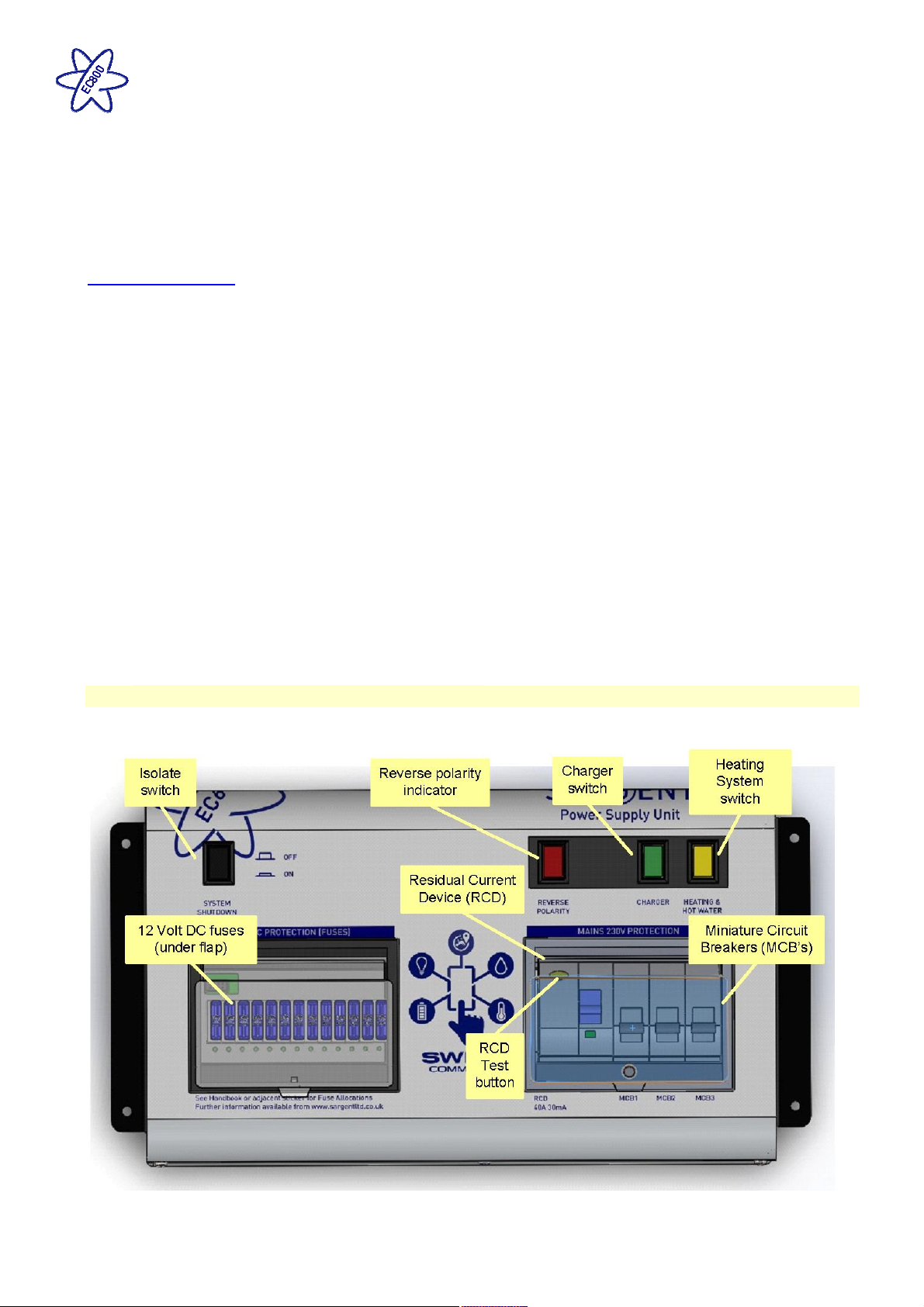
2.1 Power Supply Unit - Component Layout
The PSU is located in the front offside bed box area in caravans, and in similar locations in motorhomes.
Issue 01 Page 1 of 22 10th July 2018
Page 2

EC800 Power Control System
2.2 Activating the System
The system has a shutdown feature that can be used when the vehicle is in storage. This allows the leisure
electronics to be turned off when not required to save battery power. When in the off state the alarm and
tracking system supplies are still active, all other supplies are turned off.
Before using the system please ensure the system shutdown switch is in the on position (button in) the system
is now active.
Note: if you plan to use the Swift Command remote features the system needs to be active.
2.3 Connecting to the Mains 230V supply and Safety checks
For your safety it is IMPORTANT that you follow these connections instructions each time your Leisure Vehicle
is connected to a mains supply. This section assumes that the system is complete and that a Leisure battery
has been installed (see 3.4).
A) Ensure suitability of the Mains Supply. Your Leisure Vehicle should only be connected to an
approved supply that meets the requirements of BS7671 or relevant harmonised standards. In most
cases the site warden will hold information regarding suitability of supply. If using a generator you also
need to comply with the requirements / instructions supplied with the generator. Please note that some
electronic generators may not be compatible with your leisure system. Further generator operational
information is contained in section 3.2.
B) Switch the PSU Battery Charger / Power Converter OFF. Locate the green ‘Charger’ power switch
on the PSU and ensure the switch is in the off position (button out) before connection to the mains
supply.
C) Connect the Hook-up Lead. Firstly connect the supplied hook-up lead (orange cable with blue
connectors) to the Leisure Vehicle and then connect to the mains supply.
D) Check Residual Current Device operation. Locate the RCD within the PSU and ensure the RCD is
switched on (lever in up position). Press the ‘Test’ button and confirm that the RCD turns off (lever in
down position). Switch the RCD back to the on position (lever in up position). If the test button failed to
operate the RCD see section 3.1.
E) Check Miniature Circuit Breakers. Locate the MCB’s within the PSU (adjacent to the RCD) and
ensure they are all in the on (up) position. If any MCB’s fail to ‘latch’ in the on position see section 3.1.
F) Turn the PSU ON. Locate the black ‘Shutdown’ button and ensure it is in the on position (press button
in). Locate the green ‘Charger’ switch on the PSU and turn to the on position (press button in). The
charger switch will illuminate when turned on.
G) Check correct Polarity. Locate the ‘Reverse polarity’ indicator on the PSU and ensure that the
indicator is NOT illuminated. If the indicator is illuminated see section 3.2.
H) Check operation of equipment. It is now safe to operate the 12V and 230V equipment.
2.4 Operation while driving
The power control system is designed to shutdown parts of the system while the engine is running. This is to
meet Electro Magnetic Compatibility (EMC) regulations and to ensure the safe operation of the caravan or
motorhome. With the engine running the screen will show a warning ‘ENGINE RUNNING’.
Please ensure the system shutdown switch on the PSU is in the on (button in) position before driving (see 2.2).
This will ensure the electronic system is active and will therefore be able to control the charging process, supply
the refrigerator and monitor other system circuits.
On motorhomes if / when fitted, designated 12V sockets, en-route reading lights and en-route heating will
remain operational while the engine is running.
Some caravans may also be specified with en-route heating which will also remain operational while the engine
is running.
Issue 01 Page 2 of 22 10th July 2018
Page 3
Power Button.
EC800 Power Control System
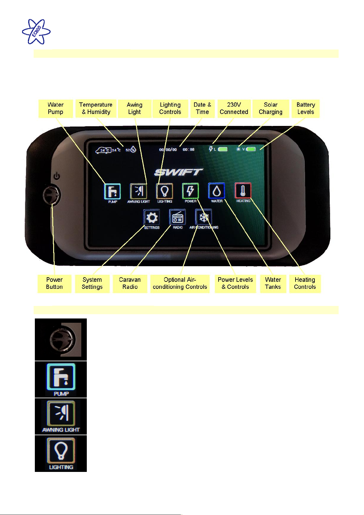
2.5 Control Panel - Layout
Your control panel will have an appearance as below, but depending on your type of vehicle (caravan or
motorhome) the control panel features will vary. Not all features are present in all vehicles.
EC800 Control Panel
2.6 Control Panel – Key Features
Press the ‘Swift’ power button to turn the leisure power on, the panel will
beep twice and show the Swift start-up logo. The control panel screen will illuminate
when the power is on, but the screen will go to sleep after a pre-determined time.
Pressing the power button or touching the screen while the screen is asleep will wake the
screen without turning the power on or off. To turn the power off press and hold the
power button to turn the power off, the panel will beep once.
Pump Button. Press the pump button to turn the water pump on. Press the button again
to turn the pump off. The button border will illuminate when the pump is on. To view the
water tank levels and other controls press the water button.
Awning Light Button. Press the awning light button to turn the awning light on or off.
The border of the button will illuminate when the awning light is on. Note the awning light
may also be controlled by the caravan alarm system or the motorhome locking system.
Lighting Button. Press the lighting button to show the lighting control screen. Here you
can turn on / off or adjust the dimmable lighting levels. Press the home button to return to
the main screen.
Issue 01 Page 3 of 22 10th July 2018
Page 4
EC800 Power Control System
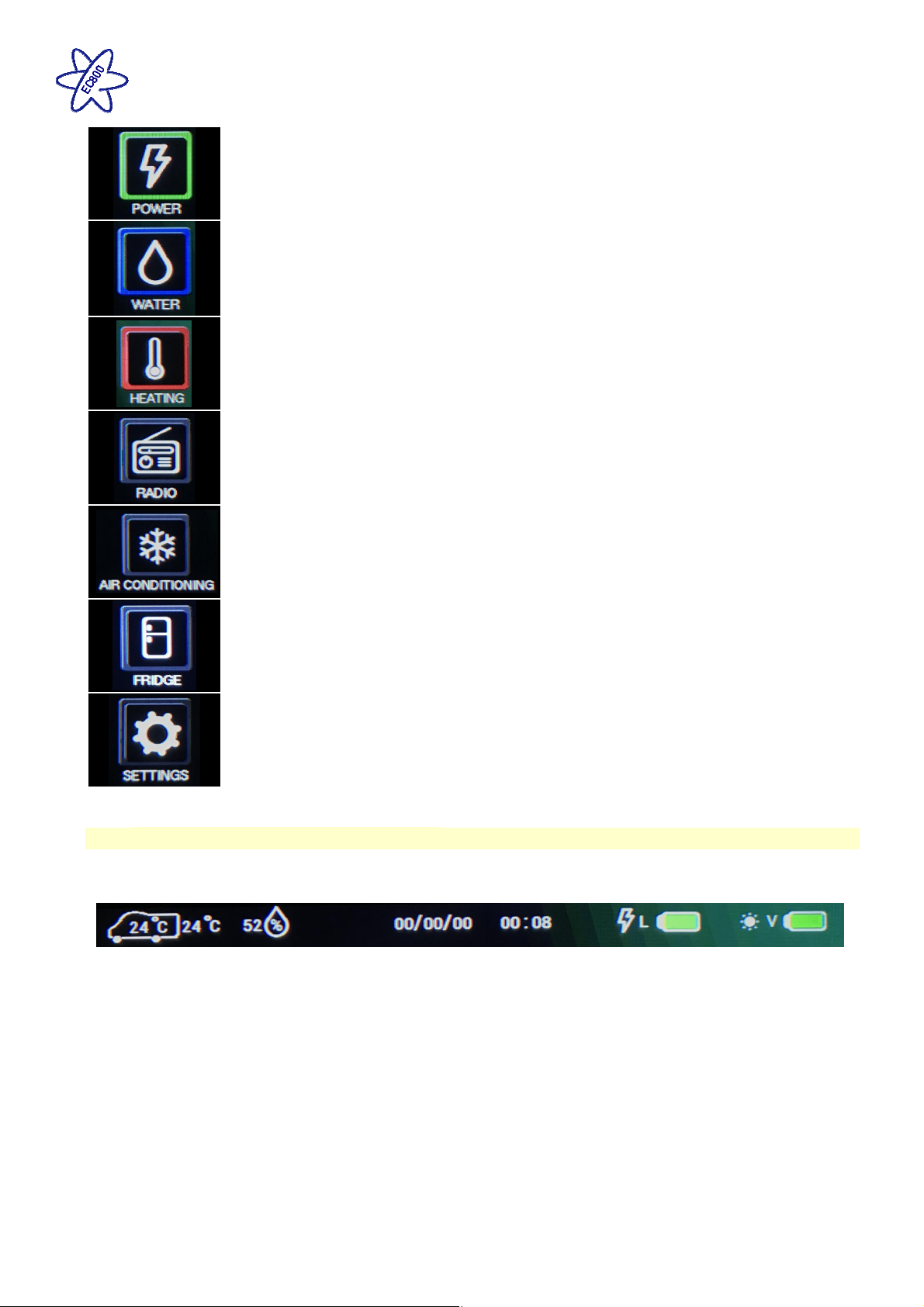
Power Button. Press the power button to show the power information and control
screen. Here you can view battery levels, view charger and solar current and press the
more button (right arrow) to view 230V current. Press the home button to return to the
main screen.
Water Button. Press the water button to show the water tank information and control
screen. Here you can view tank levels and control related features. Press the home
button to return to the main screen.
Heating Button. Press the heating button to show the heating control screen. Here you
can control the heating system, select energy and temperature and by pressing the more
button (right arrow) you can set related timers. Press the home button to return to the
main screen.
Radio Button. In caravans, press the radio button to show the radio control screen.
Depending on specification you can select FM radio, DAB radio or Aux input. Use the
buttons on screen to scan, tune or adjust the volume. Press the more button (right arrow)
to access the audio settings. Use the additional slider controls to adjust the levels. Press
the home button to return to the main screen.
Air-Conditioning Button. Press the Aircon button to show the aircon control screen.
Here you can select the operating mode, set the target temperature and adjust the fan
speed. Press the home button to return to the main screen.
Note: this button will only be visible if a CI-Bus equipped air conditioner is installed,
connected and enabled within the system.
Fridge Button. Press the fridge button to show the fridge control screen. Here you can
select the operating mode, set the cooling setting and view the temperature status. Press
the home button to return to the main screen.
Note: This button will only be visible if a CI-Bus equipped fridge is installed, connected
and enabled within the system.
Settings Button. Press the settings button to show the general settings screen. Here
you can set the date & time, screen brightness and screen on time. There are also
buttons on this screen to pair a Bluetooth device, delete Bluetooth devices, or turn the key
beep on / off. Press the home button to return to the main screen.
2.7 Control Panel ‘Header’ Information
At the top of the control panel screen there is a header or information bar which remains visible on all screens.
This is designed to provide quick reference information available at all times.
Internal and
external
temperature in
degrees Celsius.
The internal
temperature is
shown inside the
vehicle symbol.
When a battery is not being
Relative humidity,
range 1 to 100%
Current date Current time Leisure battery
status. Green =
good, Orange =
fair, Red = poor.
Lightning
symbol indicates
charging from
the 230V battery
charger.
charged a % remaining figure will
be displayed. This figure is
calculated from the battery voltage
and therefore should be used for
guidance only.
Vehicle battery
status. Green =
good, Orange =
fair, Red = poor.
Sun symbol
indicates
charging from
the solar panel.
Issue 01 Page 4 of 22 10th July 2018
Page 5
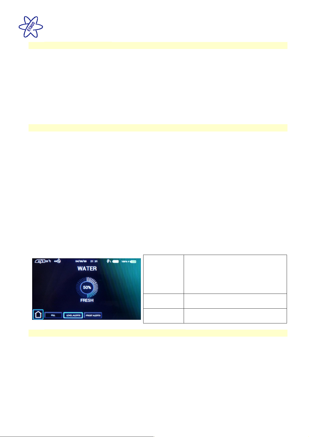
Water Tank screen (Caravan)
. Here you can view the on
-
board water tank level and control water tank
EC800 Power Control System
2.8 Temperature Readings
The EC800 system uses two sensors to measure internal temperature and humidity, and external temperature.
The internal temperature and humidity sensor is furniture mounted within the (caravan / motorhome), and the
external sensor is mounted below the (caravan / motorhome) floor. The figures displayed are for information
only, and it is hoped the information will be useful, for example when checking temperatures remotely during
cold weather.
For vehicles fitted with Alde or Truma heating systems, this sensor is not used to control the heating
temperature as it is measured above the door by the Alde or Truma room sensor. The readings on the heating
system may vary relative to the one shown on the EC800 control panel.
For vehicles fitted with a Whale heating system, the sensor is used to control the heating temperature as this
system does not have its own sensor.
2.9 Water System Operation
The EC800 control panel pump button operates the internal water pump drawing water from an on-board tank if
fitted, or an external container when no tank is fitted.
The system incorporates an automatic tank fill feature (caravan only). When turned on this will automatically fill
the on-board water tank from the external container and will switch off automatically when full. To enable tank
fill, select ‘Fill Tank’ on’ on the control panel Water screen. To ensure the external pump is not damaged if the
external tank runs dry, the pump runs for a maximum of 7 minutes.
The water tanks (fresh & waste) incorporate a level warning feature to warn the user when the fresh water level
drops below 25% or when the waste water level reaches 100%. These warnings can be enabled / disabled on
the control panel water screen.
If the water pump power is turned on and the fresh water level drops to below 25% a warning beep will be heard
and a message will be displayed on the control panel. To cancel the warning, press the confirm button.
If the water pump power is turned on and the waste water level rises to full (100%) a warning beep will be heard
and a message will be displayed on the control panel. To cancel the warning, press the confirm button.
These warnings will not be repeated unless the water pump power switch is turned off and on again. This is to
ensure the warning does not become a nuisance.
related features.
Press the tank fill button to turn on / off
the filling of the on-board water tank from
Fill Tank
the external water container. The pump
will turn off automatically when the onboard tank is full or after 7 minutes have
elapsed.
Level Alerts
Frost Alerts
Press the level alerts button turn on / off
the water tank empty warning.
Press the frost alerts button turn on / off
the frost warning.
2.10 Water Tank Heaters (frost protection) Operation
The EC652/653 (motorhome only) features the ability to switch on water tank heater to provide frost protection
for the fresh and waste tanks. The tank heaters will only operate if there is over 25% in the relevant water tank
and the external temperature sensor detects that the temperature falls below 2 degrees C. If the temperature
rises above this level the heaters will be switched off but the feature will remain on.
If the tank heaters are turned on before starting a journey, when the engine is started the tank heaters will
remain on for the duration of the journey. When the engine is stopped the tank heaters will remain on for a
further 15 minutes. If the engine is restarted within this 15 minute period the tank heaters will remain on, again
for the duration of the journey.
When the engine is stopped the tank heaters will turn off after a 15 minute period. To turn them back on you will
need to turn the control panel on and then use the tank heaters button on the water screen.
Issue 01 Page 5 of 22 10th July 2018
Page 6
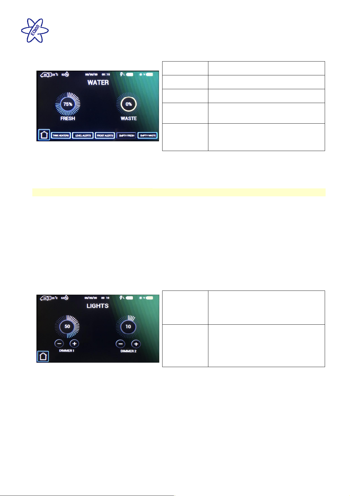
Water Tank screen
(Motorhome)
EC800 Power Control System
related features.
Note: Tank valves are normally closed and will automatically close if the power is switched off or if they have
been open for more than 10 minutes.
Note: When either tank is emptying the level gauge and the related button will flash. Press the empty button
again and confirm if you wish to cancel the emptying process.
. Here you can view the on-board water tank levels and control water tank
Tank Heaters
Level Alerts
Frost Alerts
Press the tank heaters button to turn on /
off the water tank heaters.
Press the level alerts button turn on / off
the water tank empty / full warnings.
Press the frost alerts button turn on / off
the frost warnings.
Press this button to empty the fresh water
Empty Fresh
tank (the press is followed by a confirm
button to avoid accidental operation)
Press this button to empty the waste
Empty Waste
water tank (the press is followed by a
confirm button to avoid accidental
operation)
2.11 Lighting & Dimming Operation
The system contains up to two dimming channels for groups of lights which can be dimmed, turned on and
turned off by this screen, and can also be turned on and off by furniture mounted switches.
The awning light on a caravan can be controlled by a number of items within the caravan, the local switch
adjacent to the entry door (if fitted), the alarm system lighting button, the control panel awning light button and
the App. Each item can toggle the light on or off.
The awning light on a motorhome can again be controlled by a number of items, the control panel awning light
button, the App and the lock and unlock system (dependant on system setting being set to do so). Each item
can toggle the light on or off.
The Swift Command App can be used to both configure and adjust the lighting and dimming.
Lighting screen. Here you can turn on / off or adjust the dimmable lighting levels.
Press the centre of either dial to turn the
dimmer channel on or off. In the off state
On / Off
Up / Down
the centre of the dial shows the word
OFF. In the on state the level value is
shown.
Press the (+) or (-) buttons to increase or
decrease the dimming level.
Issue 01 Page 6 of 22 10th July 2018
Page 7
EC800 Power Control System
2.12 Solar Charge Management
The EC601/602/652/653 PSU incorporates a built-in solar charge management feature, which will monitor the
input from a separate solar panel and regulator. The Solar Active symbol will be displayed on the control panel
when there is an amount of energy available to charge the battery. The voltage and current produced from the
regulator can be viewed on the control panel display by selecting the Power menu item. In a motorhome,
depending on the charge state of the batteries, the solar power will be directed to the required battery and
continuously monitored to ensure optimum operation.
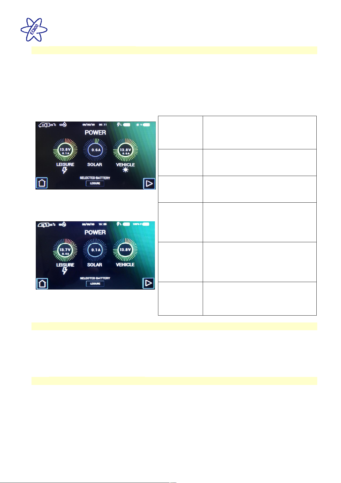
Power screen (12V). Here you can view battery levels, view charger and solar current and press the more
button (right arrow) to view 230V current.
Use the selected battery button to select
Selected
Battery
which battery you wish to use or charge
with the 230V charger. In caravans the
vehicle battery will only be available when
the caravan is plugged into the car.
If a battery is being charged by the 230V
230V
Charging
charger a ‘lightning’ symbol will be shown
below the dial and adjacent to the relevant
battery in the header area.
If a battery is being charged by the solar
Motorhome example
Solar
Charging
panel a ‘sun’ symbol will be shown below
the dial and adjacent to the relevant
battery in the header area.
The leisure dial shows the voltage of the
leisure battery. Press the centre of the
Leisure Dial
dial to change to showing the leisure
battery current (+ positive value is
charging and - negative value is
discharging)
The vehicle dial shows the voltage of the
vehicle battery. Press the centre of the
Vehicle Dial
dial to change to showing the vehicle
battery current (+ positive value is
charging and - negative value is
discharging)
Caravan Example
Solar Dial
The solar dial shows the current being
supplied to the system from the solar
panel (if fitted).
2.13 Smart Charging
The EC653/653 PSU (motorhome only) incorporates a smart charge feature, which monitors both leisure and
vehicle batteries and automatically adjusts and directs the charger power (and solar power if a solar panel is
installed) to maintain the leisure and vehicle batteries at an optimal level.
Note: If the vehicle battery is isolated using the Fiat ignition key isolator or similar, some smart charging
functionality will be lost, and the available charge will be directed to the leisure battery.
2.14 AC Current Limiter Operation
The power control system features a 230V current monitoring system which allows the mains hook up current to
be displayed on the control panel. The resolution of this reading is 0.5A. A current limit setting can be activated
which if reached will switch off the electric elements in the heating system (and air-conditioning if fitted and
enabled), until such time as the current drops and the elements will be switched back on. An example of this is if
a kettle was to be operated whilst the heating was on and the current limit was reached then the heater electric
element would be temporarily switched off, when the kettle had boiled then the heater element would be
switched back on automatically.
This feature is particularly useful when abroad on a low current supply.
Setting the value to OFF will disable this feature.
Issue 01 Page 7 of 22 10th July 2018
Page 8
EC800 Power Control System
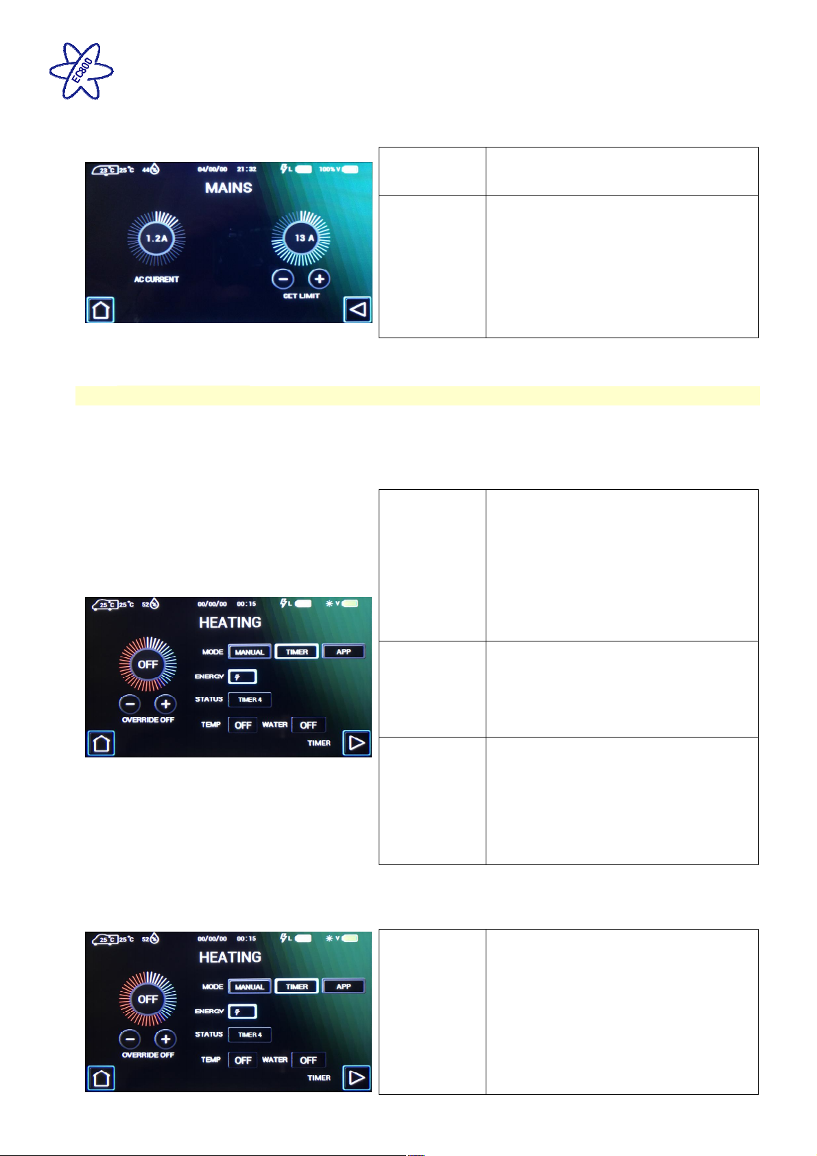
Power screen (230V). Here you can view the 230V current and set the 230V current limiter.
Note: for this feature to work correctly the Heating mode must be set to Timer so that the system can control
the heating appliance.
2.15 Heating Controls
There are a number of heating systems that can be controlled by the power control system. The system will be
preconfigured by the manufacturer or supplying dealer. The related control panel screens are shown below.
The dial on the left shows the 230V AC
AC Current
current being used by the vehicle (from
the site hook-up).
Press the centre of the dial to turn the AC
current limiter on or off. Press the (+) or
(-) buttons to increase or decrease the
limit level. When on, the system will
Set Limit
monitor the incoming AC current and if the
set limit is reached the 230V heating
element within the heating system will be
temporarily turned off until the current falls
below the set limit.
Heating screen. Here you can control the heating system, select energy and temperature and by pressing
the more button (right arrow) you can set related timers.
Set the mode to Manual to use the
controls supplied by the heating appliance
manufacturer. Set the mode to Timer to
control the appliance by the EC800
Mode
control panel.
Note: The mode will automatically change
to App when you control the appliance by
the Swift Command app.
The status box shows you which timer is
Status
Temp
Water
currently active, and the temp and water
boxes show the target room temperature
and water heater setting for the active
timer.
When operating in timer mode you can
temporarily ‘override’ the timer room
temperature by using the override feature.
Override
Press the centre of the dial to turn the
override on / off. Press the (+) or (-)
buttons to increase or decrease the
required temperature.
Note: You can also override the room temperature by making a change using the appliance control panel
(Alde & Truma only). If you make a change the override will automatically activate. The override temperature
will continue until the next timer event time.
The energy, gas or electric setting will
vary depending on the appliance type.
For Truma Combi+ heating press the
Truma CP+
Energy
energy button to step through the
available settings. Gas is indicated by the
flame symbol and electric indicated by the
lightning symbol. Possible combinations
are GAS, MIX1, MIX2, EL1 or EL2. One
electric symbol=1KW and two=2KW.
Issue 01 Page 8 of 22 10th July 2018
Page 9
EC800 Power Control System
Note: Changes made on the EC800 control panel may not be accepted on the heating controller immediately
if the controller has been recently used and still has its backlight on. Please try to use one controller at a
time.
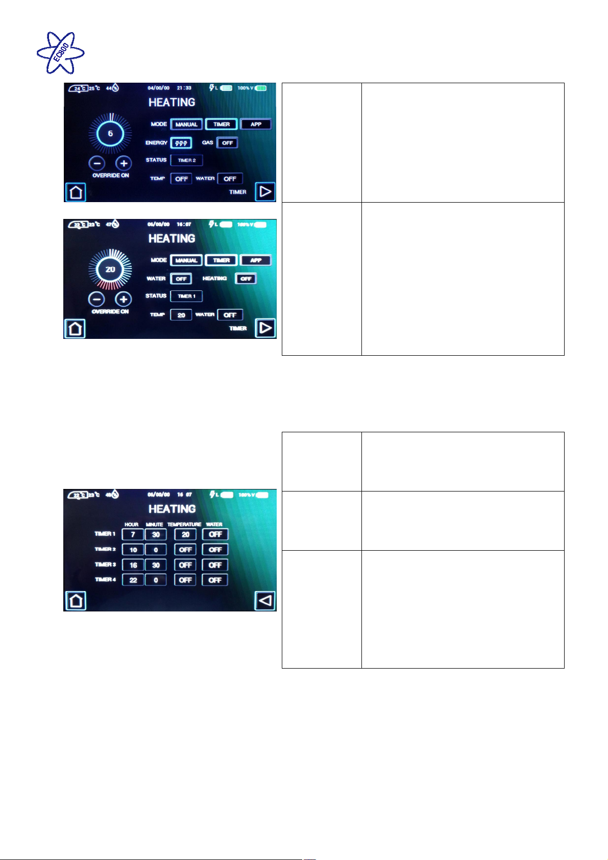
Heating timer screen. On the heating screen press the more button (right arrow) to set or view the daily
heating timers.
For Alde 3020 heating system press the
gas button to enable or disable the use of
gas. Press the electric button to step
through the available electric settings.
Alde 3020
Gas / Electric
Gas is indicated by the flame symbol and
electric indicated by the lightning symbol.
Possible combinations are electric OFF,
1KW, 2KW or 3KW and gas ON or OFF.
One electric symbol=1KW, two=2KW and
three=3KW.
For Whale air and water heating press the
air or water energy buttons to select the
required energy source for the relevant
appliance. Gas is indicated by the flame
symbol and electric indicated by the
Whale
Air Heater &
Water Heater
lightning symbol. You can select a mix of
gas and electric for the water heater.
Possible combinations for the water
heater are OFF, GAS, EL1, EL2, MIX1 or
MIX2 and for the air heater are OFF, FAN,
GAS, EL1, EL2 or EL3. See the Whale
user manual for power ratings for each
setting.
Press on the hour or minute value to
change the setting. Timers should be set
Timer
in order during the day (Timer 1 the
earliest and Timer 4 the latest) and use
the 24 hour clock.
Press the temperature values to change
Temperature
the setting. Each press will increment the
value from Off, then 5 degrees through to
30 degrees Celsius.
Press the water values to change the
setting. Each press will step through the
available setting, which vary by appliance
type.
Water
For Truma CP+ available settings are Off,
Eco or Hot.
For Alde 3020 available settings are Off,
Normal or Boost.
For Whale available settings are Off or
On.
Note: to use these timer settings the Heating mode must be set to Timer so that the system can control the
heating appliance.
Issue 01 Page 9 of 22 10th July 2018
Page 10
EC800 Power Control System
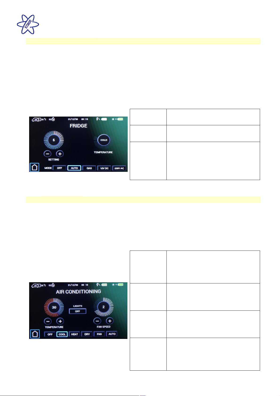
2.16 Refrigerator Controls
This section is only relevant when a CI-Bus equipped fridge is installed, connected and enabled within the
system.
The main refrigerator settings can be set / controlled by the EC800 control panel or the Swift Command app.
These controls work in parallel with the ones on the fridge control panel, so the settings can be changed by
either method.
The related control panel screens are shown below.
For information in using the fridge from the Swift Command app, please see the Swift Command User Guide.
Fridge screen. Here you can select the operating mode, set the cooling setting and view the temperature
status.
Note that the fridge will take time to react to a setting change so please allow sufficient time for the status to
update after changing a setting or adding food.
Press mode button to select the required
Mode
operating mode. Select off to turn the
fridge off.
Use the setting (+) or (-) buttons to
Setting
increase or decrease the cooling setting.
1 is low and 5 is maximum.
The temperature status display shows the
temperature state of the fridge, with the
optimal (central) position being the ideal.
Temperature
If the fridge is too warm increase the
cooling setting to reduce the temperature.
If the fridge is too cold reduce the cooling
setting accordingly.
2.17 Air-conditioning
If your vehicle has been fitted with a compatible air-conditioning unit then the settings can be set / controlled by
the EC800 control panel, the air-conditioner infrared remote control or the Swift Command app. The unit must
be turned on with its power switch before it can be controlled.
The related control panel screens are shown below. For information in using the air-conditioning from the Swift
Command app, please see the Swift Command User Guide.
Air-conditioning screen. Here you can select the operating mode, set the target temperature and adjust the
fan speed.
Press the lights button to control the LED
light built into the air-conditioning unit.
Lights
Select on or off to turn the light on or off,
or select dimmed to allow the light to be
controlled with other dimmable lighting in
the vehicle.
Press mode button to select the required
operating mode. Select off to turn the air-
Mode
conditioner off.
Note that available modes vary according
to the model of air-conditioner fitted.
Use the temperature setting (+) or (-)
buttons to increase or decrease the
Temperature
temperature setting. Available settings
range from 5 degrees to 30 degrees
Celsius.
Use the fan speed setting (+) or (-)
buttons to increase or decrease the fan
Fan Speed
setting.
Note that available settings vary
according to the model of air-conditioner
fitted.
Issue 01 Page 10 of 22 10th July 2018
Page 11
EC800 Power Control System
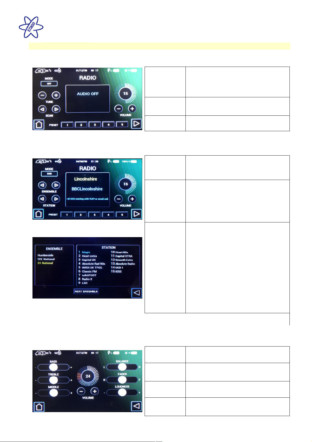
2.18 Caravan Radio
Radio screen. Here you can select the radio mode, scan for stations, tune or adjust the volume.
Note: Aux can be used when a device is connected to the radio module using the 3.5mm jack plug, either on
the side of the radio module or on the binnacle at the front of the caravan (depends on model specification).
Set the device volume to a mid-setting and then adjust on the EC800 control panel. If the sound level is too
low increase the device volume, or if the sound is distorting reduce the level.
Note: DAB reception may be temporarily interrupted by poor signal or when using electrically ‘noisy’
equipment or appliances (for instance hob ignition).
Audio screen. On the radio screen press the more button (right arrow) to access the audio settings. Use the
additional slider controls to adjust the levels.
Press the mode button to select the
required radio mode, available choices
Mode
vary by specification and include FM,
DAB, Aux 3.5mm input or Off.
Select Off to turn the radio off.
Press the (<) or (>) buttons to scan
Scan
forward for the next station or to scan
backwards for the previous station.
Tune
Press the (+) or (-) buttons to increase or
decrease tuned frequency.
Press the (+) or (-) buttons to increase or
Volume
decrease the volume level. Press on the
centre of the dial to mute the volume,
press again to restore the volume level.
The 5 pre-set buttons are used to store
and retrieve your favourite stations.
To store a station, firstly scan or tune to
Preset
the required station, then press and hold
the pre-set number until you hear a beep.
To retrieve a station simply press the
required pre-set button.
When using the DAB radio, the channels
are grouped into ensembles. You can
scan for channels within an ensemble by
pressing the (<) or (>) button.
You can also press on the central channel
information window to show a full list of
DAB Channel
List
ensembles and their channels.
Press the next ensemble button to scan
for channels in the next available
ensemble.
You can select an ensemble by pressing
on it in the left side list. You can select a
station by pressing on it in the right side
list. Press the < button to return to the
radio screen.
Tone
Use the slider bars to adjust the treble,
middle or bass levels.
Use the loudness slider to further adjust
Loudness
some audio frequencies to suit
requirements.
Balance
Use the balance slider to adjust the levels
between the left and right speakers.
For installations with 4 speakers, use the
Fader
fader slider to adjust the levels between
the front and rear speakers.
Issue 01 Page 11 of 22 10th July 2018
Page 12
Bluetooth
EC800 Power Control System
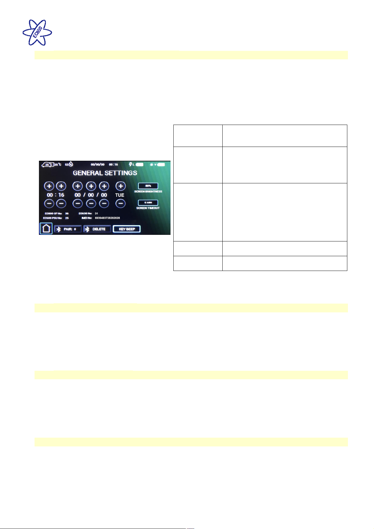
2.19 Bluetooth Pairing & Other Controls
The EC800 control panel can display the software version number of the Control Panel, the PSU and the
communicator / tracking unit. Press the settings button to view the setting screen which contains the related
information.
The Bluetooth pairing process is covered below. Further help with Bluetooth pairing is available in the form of a
help video which can be viewed on the Sargent website in the Support Information section.
General settings screen. Here you can set the date & time, screen brightness and screen on time.
Time, Date &
Day
Press the (+) or (-) buttons above or
below each item to adjust the value. Note
that the system uses the 24 hour clock.
Press on the screen brightness button to
Screen
settings
adjust the screen backlight level.
Press on the screen timeout button to
select the time that the screen will stay
illuminated for after a press or touch.
Press the pair button to start pairing with
your compatible Bluetooth device. The
pair button border will illuminate when
Bluetooth
Pair
pairing is active.
You can now pair your device to the
system following the devices instructions.
Pairing remains active for 1 minute and is
then turned off automatically.
Press the delete button to delete any
Delete
Key Beep
Bluetooth pairings from the system.
Use the key beep button to turn on / off
the beep sound when a button is pressed.
Note that setting changes are saved when you press the home button to return to the main screen.
2.20 Electric Step Operation
On vehicles fitted with an electric step, this is operated by a button near the entry door. Press and release the
button to move the step in or out. One press of the button will move the step out; a further press will move the
step in again.
If the engine is started the step will move in automatically, after a short warning buzzer. If this operation fails
due to an obstacle a buzzer will sound continuously to warn that the step is still out, and therefore requires your
attention.
2.21 AL-KO ATC Operation
On caravans fitted with Al-Ko Automatic Traction Control, the Swift Command App can be used to monitor the
status of the ATC from within your tow vehicle. More information on this can be found within the Swift
Command App and the associated user guide.
Note: if using the Swift Command app to monitor the ATC whilst driving the phone or device must be placed in a
suitable holder and setup before driving. At all times ensure you obey the legal requirements for using mobile
devices in vehicles.
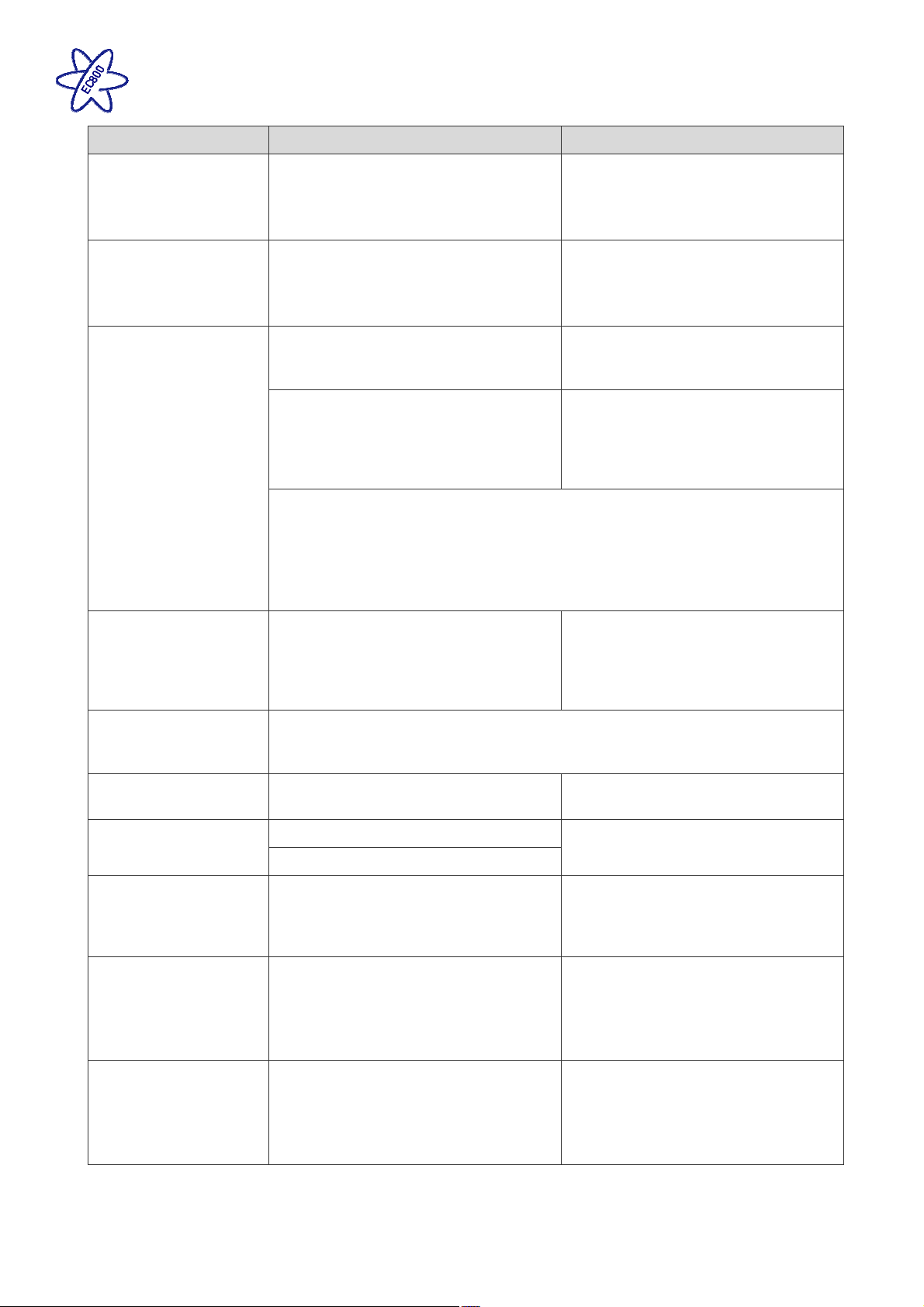
2.22 System Warnings
The system incorporates a number of warnings that are active at specific times. These are summarised below,
and also covered by relevant sections of this manual.
When a warning is active a warning box will appear on the control panel screen containing a description of the
warning along with an audible beeping sound.
Issue 01 Page 12 of 22 10th July 2018
Page 13
EC800 Power Control System
Warning When Type
Fresh water level low
Waste water level full
With pump turned on and fresh water
level low (less than 25% full)
Only available when an on-board tank
Message on screen and 60 second
audible beep
is fitted
With pump turned on and waste water
level full.
Only available when an on-board tank
Message on screen and 60 second
audible beep
is fitted
Leisure battery voltage
low
Leisure battery voltage
high
Vehicle battery
warnings
Engine running
With control panel power on and leisure
battery selected (as active battery) and
the voltage level falls below 10V
Message on screen and 60 second
audible beep.
Message on screen and 60 second
With control panel power on and leisure
battery selected (as active battery) and
the voltage level is below 9V
audible beep. If no action taken after
30 seconds then the system will
switch the power off to prevent severe
discharge of the battery
Note: This is an emergency cut off level to protect the battery from severe
damage. You should not rely on this cut off level during normal operation, but
manage your power consumption to a discharge level of 11.5V or above.
This cut off only applies to power drawn from the battery by the leisure
equipment that is controlled by the control panel power switch; it will not protect
the battery from discharge by permanently connected equipment.
With control panel power on or off and
leisure battery is selected (as active
battery) and the voltage level rises
above 15V
Message on screen and repeated
beeps from the control panel. The
power is automatically turned off. The
beeping will not stop until the fault is
cleared.
If the vehicle battery is selected instead of the leisure battery, then similar
warnings to those described above are applied to the vehicle battery. The
vehicle battery low warning level is 10.9V
When the engine is started the system
power will be turned off
Message on screen stating ‘engine
running’.
Step extended
Mains lead (hook-up
cable) still connected /
plugged in
Heating system
Refrigerator / Fridge
Freezer
Step extended and engine started
Step jammed or obstructed
When the engine is started and the
mains cable is still plugged in and the
charger is switched on
When set to control the heating system,
the EC800 control panel will show
related heating system warnings, which
will include the error number and error
description
When set to control the refrigerator, the
EC800 control panel will show related
warnings which will include the error
number and error description
Message on screen and warning
buzzer
Message on screen and repeated
beeps from the control panel. The
beeping will not stop until the hook-up
lead is removed.
Message on screen and 60 second
audible beep.
Additional descriptive information is
available when using the Swift
Command App.
Message on screen and 60 second
audible beep.
Additional descriptive information is
available when using the Swift
Command App.
Issue 01 Page 13 of 22 10th July 2018
Page 14
EC800 Power Control System
3 System Technical Information
The following section provides further technical information relating to the electrical system. You can also
access the supporting technical manual from www.sargentltd.co.uk
3.1 Residual Current Device & Miniature Circuit Breakers
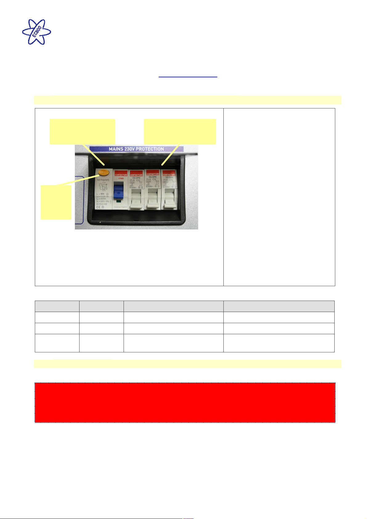
The Residual Current Device (RCD) is
basically provided to protect the user
Residual Current
Device (RCD)
RCD
Test
button
Miniature Circuit
Breakers (MCB’s)
from lethal electric shock. The RCD
will turn off (trip) if the current flowing
in the live conductor does not fully
return down the neutral conductor, i.e.
some current is passing through a
person down to earth or through a
faulty appliance.
To ensure the RCD is working
correctly, the test button should be
operated each time the vehicle is
connected to the mains supply (see
section 2.3)
The Miniature Circuit Breakers
(MCB’s) operate in a similar way to
traditional fuses and are provided to
protect the wiring installation from
overload or short circuit. If an
overload occurs the MCB will switch
off the supply. If this occurs you
should investigate the cause of the
fault before switching the MCB back
on.
The following table shows the rating and circuit allocation for the three MCB’s
MCB Rating Output Wire Colour Description
1 10 Amps White 230V Sockets
2 16 Amps White (Yellow for heater) Extra 230V Sockets / Heating System
3 10 Amps
Black (Blue for Whale water
heater)
Fridge / Charger / Auxiliary devices /
Whale Water Heater
3.2 Generator Usage
Caution should be used before connecting a generator to your caravan or motorhome.
WARNING
Never start or stop the generator while electrical loads are connected and switched on. Start the engine, let
it stabilise and then connect the electrical load. When stopping the generator, disconnect the electrical load
and let engine stabilise before switching off.
Whilst some generators use electronic inverter technology, others use a more basic principle to generate the
230V supply. Preference should be to choose a generator which produces a consistent sinusoidal wave form
with accurate voltage control.
The Reverse Polarity warning light on the PSU may illuminate when using a Generator. This is a normal side
effect when using some types of generator. Instead of connecting the neutral conductor to earth, some
generators centre tap the earth connection making both neutral and live conductors 110V above earth. This
110V difference causes the neon polarity indicator to illuminate.
In most cases it is safe to use a generator, but please consult the generator handbook for further information.
Issue 01 Page 14 of 22 10th July 2018
Page 15
EC800 Power Control System
3.3 Battery Charger
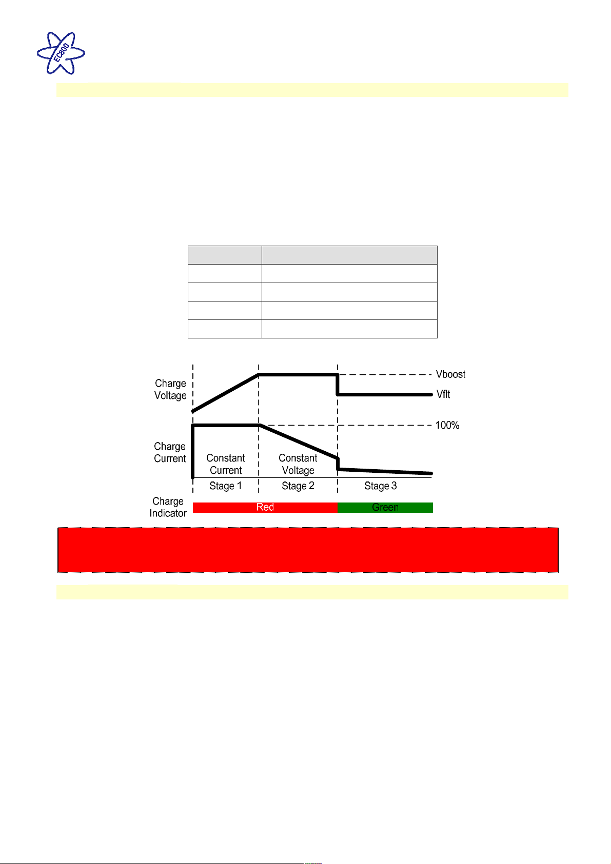
The system incorporates an intelligent three-stage battery charger.
During stage 1 the battery voltage is increased gradually while the current is limited to start the charging
process and protect the battery. At stage 2 the voltage rises to 14.4V to deliver the bulk charge to the battery.
When the battery is charged, the voltage is decreased at stage 3 to 13.6V to deliver a float charge to maintain
the battery in the fully charged state. The charger can be left switched on continuously as required.
The battery charger / power converter also provides power to the leisure equipment when the mains supply is
connected. This module supplies DC to the leisure equipment up to a maximum of 25 Amps (300 Watts),
therefore the available power is distributed between the leisure load and the battery, with the leisure load taking
priority as per the following example:
Leisure load Available power for battery charging
5A 20A
10A 15A
15A 10A
20A 5A
WARNING
Under heavy loads the Battery Charger case may become hot. ALWAYS ensure the ventilation slots have
a clear flow of air. Do not place combustible materials against / adjacent to the charger.
3.4 Leisure Battery
A) Type / Selection
For optimum performance and safety it is essential that only a proprietary brand LEISURE battery is used and it
is suggested to select a battery from the NCC Verified Battery Scheme with a typical capacity of 75 to 120 Ah
(Ampere / hours). Depending on the prospective use of the vehicle the correct type should be selected (A, B or
C). A normal car battery is NOT suitable. This battery should always be connected when the system is in use.
The PSU is configured to work with standard lead acid leisure batteries, and in most cases is also compatible
with the latest range of Absorbed Glass Matt (AGM) batteries. The system is also suitable for Lithium batteries
with built-in Battery Management Systems BMS). Before fitting non-standard batteries please check that the
charging profile described in 3.3 is suitable for the type of battery by referring to the battery documentation or
battery manufacturer.
Some vehicle installations can cater for two leisure batteries connected in parallel. In these cases it is
recommended that two identical batteries are used.
The battery feed is fitted with an inline fuse between the battery and the electrical harness, and is usually
located immediately outside the battery compartment or within 500mm of the battery. The maximum rating of
this fuse is 20A per battery. If a single battery is fitted to a motorhome, this fuse could be up to 40A, however if
two batteries are fitted each battery should be fused at a maximum of 20A.
Issue 01 Page 15 of 22 10th July 2018
Page 16

EC800 Power Control System
B) Installation & Removal
Always disconnect the 230V mains supply and turn the PSU green charger switch to the off position (button out)
before removing or installing the battery.
When connecting the battery, ensure that the correct polarity is observed (black is negative [-] and red is
positive [+]) and that the terminals are securely fastened. Crocodile clips must not be used.
WARNING
Explosive gases may be present at the battery. Take care to prevent flames and sparks in the vicinity of
the battery and do not smoke.
C) Operation / Servicing
Under normal circumstances it should not be necessary to remove the battery other than for routine inspection
of the terminals and “topping up” of the battery fluid where applicable. Please see instructions supplied with the
battery.
Note: Do not over discharge the battery. One of the most common causes of battery failure is when the battery
is discharged below the recommended level of approximately 10V. Discharging a battery below this figure can
cause permanent damage to one or more of the cells within the battery.
To prevent over discharge, the power control system incorporates a battery protect circuit that warns the users
and then disconnects the batteries when they fall below set values.
If a warning is active a beep will be emitted by the control panel and information will be shown on the screen.
To cancel the warning, press the select button. These warnings will not be repeated unless the power switch is
turned off and on again. This is to ensure the warning does not become a nuisance.
Battery
Vehicle 10.9V
Voltage
cut off
Action after cut off Notes
Battery selection is
changed from Vehicle
battery to Leisure
battery. If the leisure
battery is below 9V
then a further warning
will occur (see below).
This cut off level is designed to protect the vehicle
battery from over discharge. The 10.9V level
ensures there is sufficient power in the battery to run
the vehicle electronics and start the vehicle. This
cut off only applies to power drawn from the battery
by the leisure equipment; it will not protect the
battery if you leave vehicle circuits switched on,
such as the road lights.
This is an emergency cut off level to protect the
battery from severe damage. You should not rely on
this cut off level during normal operation, but
manage your power consumption to a discharge
Leisure 9V Power is turned off
level of about 11.5V.
This cut off only applies to power drawn from the
battery by the leisure equipment that is controlled by
the control panel power switch; it will not protect the
battery from discharge by permanently connected
equipment.
Issue 01 Page 16 of 22 10th July 2018
Page 17
EC800 Power Control System
3.5 12 Volt DC Fuses
WARNING
When replacing fuses always replace a fuse with the correct value. NEVER replace with a higher value /
rating as this could damage the wiring harness. If a replacement fuse ‘blows’ do not keep replacing the
fuse as you could damage the wiring harness. Please investigate the fault and contact your dealer.
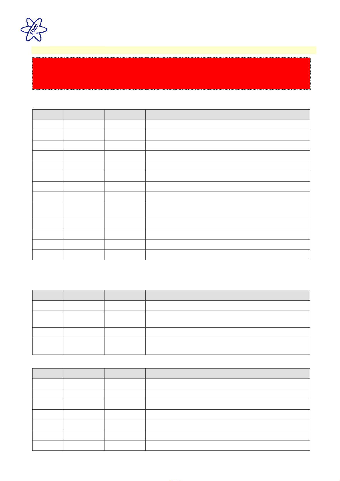
The following table shows the fuse allocation for the 13 fuses fitted to the PSU. Please note that fuses are
dependant on PSU versions, so not all fuses may be present.
Fuse Rating Fuse Colour Description
1 25 Amps White Charger
2 7.5 Amps Brown Permanent 12V / Alarm / Fridge Electronics
3 10 Amps Red 12V Sockets / TV Amplifier / Radio (Caravans Only)
4 10 Amps Red Extractor Fans
5 5 Amps Tan Appliances / Hob Ignition / Toilet / Whale Water Heater
6 10 Amps Red Water Pumps / Tank Heaters (Motorhomes Only)
7 7.5 Amps Brown Lighting, Main Lights & Dim Channel 1
8 7.5 Amps Tan Lighting, Entry Light & Dim Channel 2
9 10 Amps Red
Alde Heating, Truma Heating, Whale Air Heater, Motorhome
Marker Lights, Motorhome En-Route Sockets & Lights
10 10 Amps Red Auxiliary / Awning Light / Electric Step (Motorhomes Only)
11 20 Amps Yellow Fridge 12V (Motorhome Only)
12 15 Amps Blue Towing 12V (Motorhome Only)
13 15 Amps Blue Fridge D+ (Motorhome Only)
Note: Fuses (2-13) have a Red LED below them which provides indication that the fuse has blown. The
charger fuse has a green LED which Indicates that the charger is working.
The following table shows details of the fuse(s) located at the Leisure battery.
Fuse Rating Fuse Colour Description
Battery 1 20 Amps Yellow Fuse remotely located near battery on a Caravan
Battery 2 20 Amps Yellow Fuse remotely located near battery 2 (where fitted) on a
caravan
Battery 1 40 Amps Orange Fuse remotely located near battery on a Motorhome
Battery 2 40 Amps Orange Fuse remotely located near battery 2 (where fitted) on a
Motorhome
The following table shows details of the fuse(s) located at the C44 Road Light fuse box (caravans only)
Fuse Rating Fuse Colour Description
1 20 Amps Yellow Fridge Supply
2 5 Amps Tan Left Hand Tail Lights
3 5 Amps Tan Right Hand Indicators
4 5 Amps Tan Fog Lights
5 - - Spare location
6 20 Amps Yellow Car Battery Supply
7 5 Amps Tan Right Hand Tail Lights
Issue 01 Page 17 of 22 10th July 2018
Page 18
EC800 Power Control System
8 5 Amps Tan Left Hand Indicators
9 7.5 Amps Brown Stop Lights
10 5 Amps Tan Reverse Lights
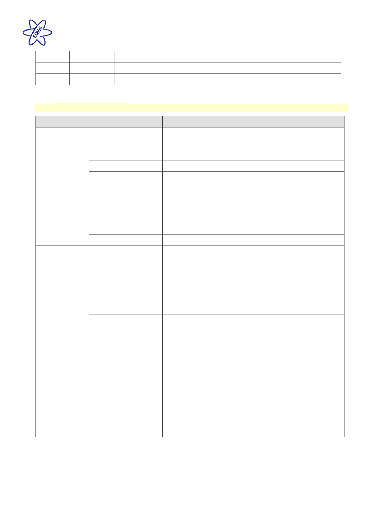
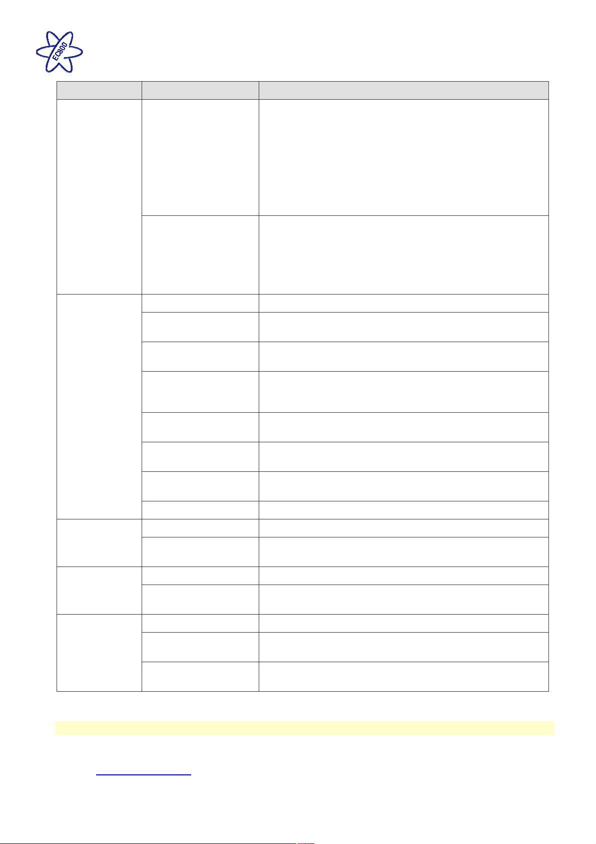
3.6 Common Fault Table
Fault Possible Cause Proposed Fix
Connecting lead
between the site and
Leisure Vehicle not
Check and connect lead as per 2.3C
connected
RCD switched off Reset RCD as per 2.3D
No 230 volt
output from PSU
Reverse Polarity
light is
illuminated on
PSU
RCD not operating
correctly
Check supply polarity; if the RCD continues to fail contact your
Dealer as there is probably an equipment or wiring fault.
Reset MCB by switching OFF (down position) then back ON
MCB switched off
(up position), if the MCB continues to fail contact your Dealer
as there is probably an equipment or wiring fault.
No or deficient supply
from site
Contact site Warden for assistance.
Other fault Contact your Dealer.
The reverse polarity light is designed to illuminate when the
Live and Neutral supply has been reversed / crossed over. If
the light illuminates there is a problem with the site supply or
Mains Supply
reversed?
the cable connecting the supply to your vehicle. The light is
designed to work on UK electrical supplies (where the neutral
conductor is connected to earth at the sub station). If you are
using your vehicle outside the UK this light may illuminate
when no fault exists. In these cases consult the site warden for
advice.
‘The Reverse Polarity warning light is on when using my
Generator’.
This is a normal side effect when using some types of
generator. Instead of connecting the neutral conductor to
Generator being used
earth, some generators centre tap the earth connection
making both neutral and live conductors 110V above earth.
This 110V difference causes the neon polarity indicator to
illuminate. In most cases it is still safe to use the generator,
but please consult the generator handbook for further
information.
Check batteries and fuses, turn PSU isolate switch and
charger switch on and ensure mains supply is connected.
Control Panel
Problems
Control Panel has no
display
Check control panel connecting lead at PSU and behind
Control Panel.
Contact your Dealer.
Issue 01 Page 18 of 22 10th July 2018
Page 19
EC800 Power Control System
Fault Possible Cause Proposed Fix
Battery protect feature has operated to protect the Vehicle
battery and or the Leisure battery. See 3.4C
Over voltage protection has been activated, the control panel
will display a warning. A number of things can cause this but
12V Power turns off
the most common is the solar panel, it is worth checking the
regulator is connected correctly and operating within the
correct parameters.
Engine has been started, all equipment has been
disconnected to meet EMC requirements. See 2.4
Observe control panel handling instructions.
Control panel software may have crashed. Reboot control
Control Panel locked /
erratic function
panel by turning off the PSU isolate switch. Wait 30 seconds
then turn the switch back on. Check with your dealer that your
system has the latest software installed, as an update may be
available.
No 230V supply Check all above.
No 12 volt
output from PSU
Pump not
working
Lights not
working
Charger not switched
on
Battery not connected
and / or charged
Turn charger switch on, switch will illuminate.
Install charged battery as per 3.4
Power button on control
panel not switched to
Turn power on at control panel.
on
Battery flat / Battery
fuse blown
Fuse blown
Equipment switched off
/ unplugged
Recharge battery, check fuses, check charging voltage is
present at battery.
Check all fuses are intact and the correct value fuse is
installed as per fuse table.
Check equipment is switched on and connected to the 12V
supply.
Other fault Contact your Dealer.
Fuse blown Replace fuse with correct value as per fuse table.
Pump turned off
Turn pump on by pressing the pump button at the control
panel.
Fuse/s blown Replace fuse with correct value as per fuse table.
Lights turned off
Turn Lights on by pressing the lights button, use dimmer at the
control panel.
Bluetooth not paired Using System Settings menu, select Bluetooth Pair option.
Communications
not working
Bluetooth not active on
Device
Bluetooth out of range
Ensure that the handheld device has Bluetooth switched on
and that the device supports the Bluetooth 4 standard (BLE).
Ensure the handheld device is within 7M of the middle of the
caravan / motorhome.
3.7 Contact details
Sargent Electrical Services Limited provide a technical help line during office hours. Please contact 01482
678981 if you require technical help. For out of hour support please refer to the support section of the Sargent
web site www.sargentltd.co.uk
Issue 01 Page 19 of 22 10th July 2018
Page 20

EC800 Power Control System
4 Remote Access & Control
4.1 Swift Command App
The Swift Command app can be down loaded from the Apple App Store or the Android Play store.
A separate Swift Command User Guide is available which covers the operation of the app.
Before you can use the App with your caravan or motorhome you will need to create an account and sign up to
the free communication service. This is a simple process and will be explained further by your dealer at the
vehicle handover. Additional information is available at www.swiftcommand.co.uk
4.2 Swift Command Web usage & Description
In addition to the mobile App, you can also use the same account and login details to access the Swift
Command web site.
Here you can update and amend your details, look at location information and history, review system
information and historical data as well as changing some system options and settings.
4.3 Swift Command SIM Coverage & Usage information
The EC600 system contains Mobile SIM with 36 month contract, which commences upon activation at the
Dealership when your vehicle is linked to your customer.
Below is a list of the countries covered by the SIM under a fair usage policy, a complete list is available at
request.
Austria, Belgium, Bulgaria, Cyprus, Czech Republic, Denmark, Estonia, Finland, France, Germany, Greece,
Hungary, Iceland, Ireland, Italy, Latvia, Liechtenstein, Lithuania, Luxembourg, Netherlands, Malta, Norway,
Poland, Portugal, Romania, Slovakia, Slovenia, Spain, Sweden, United Kingdom.
For vehicles shipping direct to Australia or New Zealand a special world-wide SIM is fitted at the Swift factory.
Please note that if a UK specification vehicle is shipped to these countries the remote features will not operate.
4.4 Replacement parts
The Control panel contains a small lithium battery to maintain the clock when no other energy supplies are
available this will last in excess of 5 years under normal conditions. The battery is a CR2032 3.0V
The EC630 Communication module contains a special backup battery pack which should last in excess of 3
years under normal conditions. The pack part number is 16308 available from Sargent.
4.5 Updates
From time to time there may be updates to the system firmware; these updates will be done at service intervals
by your dealership.
Issue 01 Page 20 of 22 10th July 2018
Page 21
EC800 Power Control System
5 Technical Data & Approvals
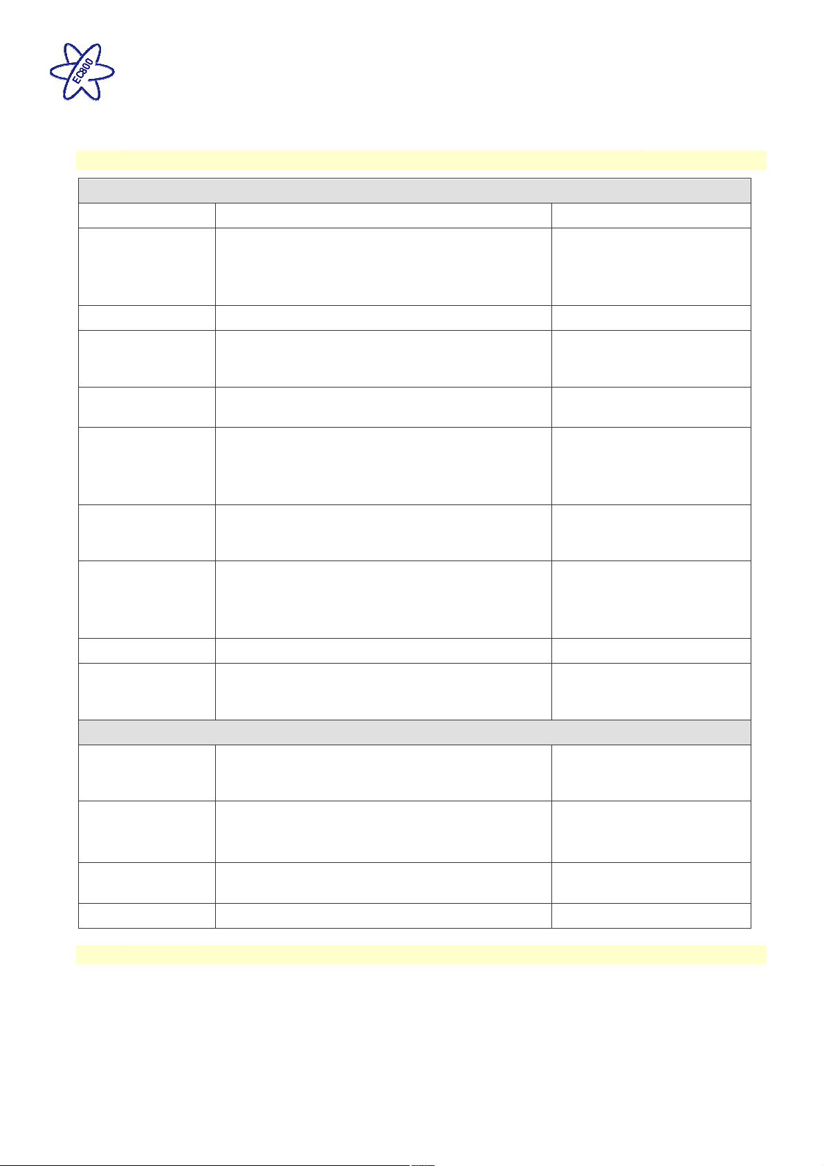
5.1 Equipment – EC601, EC602, EC652, EC653, EC800, EC635 & PX300
Outline Specification
INPUT 230V 230 Volts / 0 to 16 Amps + / - 10%
OUTPUT 230V
INPUT 12V 2 x 20A battery inputs via 2 x 4 way connectors
RCD protected, 2 x MCB outputs of 10A & 1 x MCB
output of 16A
Separate switched channels for heating system and
charger
1 X Dedicated solar panel input capable of
SOLAR INPUT
supporting 10A of solar power input (typically 180 to
200W) via a 2 way connector
OUTPUT 12V
25A total output via multiple switched channels
protected by 13 fused outputs
Input 220-240 Volts AC +/- 10%, Frequency 50 Hz
Integrated
CHARGER
+/- 6%, Current 3A max.
DC Output 13.6 to 14.4 Volts nominal, Current 25
Amps max (300 Watts).
4 x Fresh water level, 4 x Waste water level, 1 x
Signal INPUT
Engine running, plus multiple vehicle connections,
sensor inputs for temperature & humidity
CANBUS Data communication and power to Control
Data IN / OUT
Panel via 6 way connector
CI-Bus Data communication to CI-Bus enabled
devices via RJ11/12 connector
IP rating IP31
Operating
temperature
Ambient 0 to 35° Celsius
Charger case temperature with full load 65° C Max
Dimensions
Check the solar panel rating
plate to ensure the maximum
current is <= 10A
Fresh water negative sensed
Waste water negative sensed
Automatic shutdown and
restart if overheated /
overloaded
EC601, EC602,
EC652 & EC653
PSU
EC800 Control
Panel
EC635 Comms
Module
Overall size (HxWxD) 180 x 305 x 135mm
Clearances 75mm above, 50mm left & right
Overall size (HxWxD) 125 x 279 x 25mm
Cut-out size (HxW) 108 x 173mm + switch area
Weight 3.8 Kg
Fixing centres 250mm X
74mm
Weight 380g
Overall size (HxWxD) 55 x 116 x 85mm Weight 550g
EC840 Sensor Overall size (HxWxD) 20 x 35 x 38mm Weight 10g
5.2 Approvals
System: BSEN 1648-1, BSEN1648-2 compliant, BS7671: 2008 compliant
Residual Current Device: RCD 40A 30mA trip to BS EN 61008
Miniature Circuit Breakers: MCB’s type C 6000A breaking capacity to BSEN 60898
Electro Magnetic Compatibility (EMC) directive 2004/108/EC Certificate CE20071224-1
Integrated Charger: BS EN 60335-1/2.29, 2006/95EC, IEC61000-3.2/3:1995, 1.
Low Voltage Directive: 2006/95EC TUV-014900-A1, EN55022, Class B, EN55024/ Level 2
Issue 01 Page 21 of 22 10th July 2018
Page 22
EC800 Power Control System
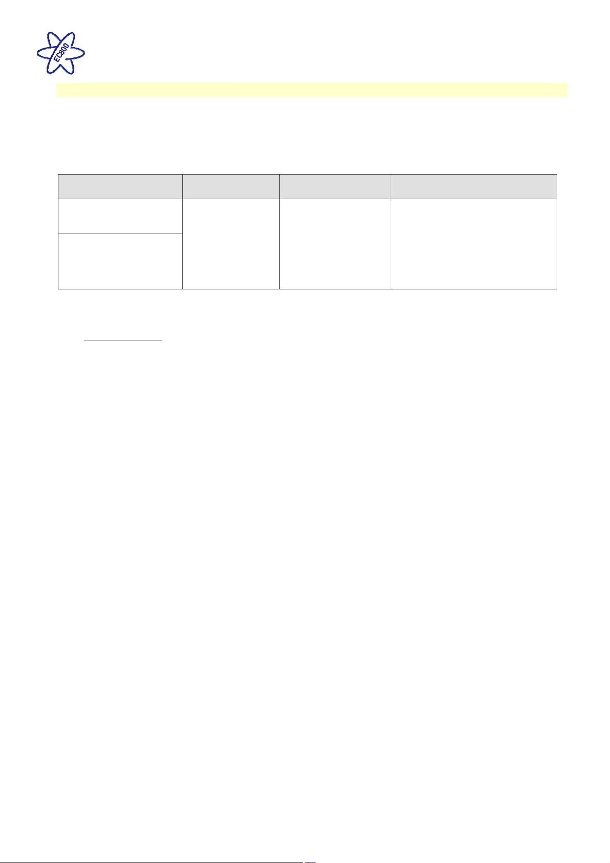
5.3 Declaration of Conformity
Equipment: Leisure Power Control System Model name: EC601, EC602, EC652, EC653, EC800, EC635 &
PX300
I hereby declare that the equipment named above has been designed to comply with the relevant sections of
the above referenced approvals. The unit complies with all essential requirements of the Directives.
Signed Name Position Manufacturer
I L Sargent Technical Director Sargent Electrical Services Ltd
Unit 35, Tokenspire Business
Park
Date:
Woodmansey, Beverley
East Yorkshire, United Kingdom
Whilst every effort has been made to ensure the accuracy and completeness of this document, no guarantee is given against errors or
omissions. This document may be updated / improved orver time therefore please check with your dealer / supplier for update information
or visit www.sargentltd.co.uk
Issue 01 Page 22 of 22 10th July 2018
 Loading...