

SWF SB Series, Multi-Heads E Series, DM-WU656-150, DM Series, DM-WU2X656-150 User Manual
...
MMEEEE--110011220011
USER
’’
S MANUAL
SSuunnSSttaarr CCOO..,, LLTTDD..
Operating Manual
••
SB Series
••
Multi-Heads E-Series
••
DM Series
••
K Series


1. THIS IS AN INSTRUCTION FOR SAFE USE OF AUTOMATIC
EMBROIDERY MACHINES. READ THOROUGHLY BEFORE USE.
2. CONTENTS IN THIS INSTRUCTION MAY CHANGE, WITHOUT
PRIOR NOTICE, FOR IMPROVEMENT OF MACHINE QUALITY AND
THUS MAY NOT CORRESPOND TO THE MACHINE YOU
PURCHASED. CONTACT YOUR SALES AGENT FOR INQUIRIES.
3. THIS IS DESIGNED AND MANUFACTURED AS AN INDUSTRIAL
MACHINE. IT SHOULD NOT BE USED FOR OTHER THAN
INDUSTRIAL PURPOSE.

CCoonntteennttss
1.0 Operation Box .......................................................................................................................... 1-1
1.1 Part Name and Function ................................................................................................................................ 1-1
2.0 Basic Steps Before Starting Embroidery ............................................................................. 2-1
2.1 Embroidery Machine Power-On .................................................................................................................. 2-1
2.2 Basic Steps ..................................................................................................................................................... 2-4
3.0 Operating Program Install ...................................................................................................... 3-1
3.1.0 SWF Install Program ..................................................................................................................................... 3-2
3.1.1 Install .............................................................................................................................................. 3-2
3.1.2 Backup ............................................................................................................................................. 3-4
3.1.3 Memory ........................................................................................................................................... 3-5
3.1.4 System ............................................................................................................................................. 3-7
3.2.0 Machine Setting Change ............................................................................................................................... 3-9
3.2.1 Embroidery Machine Specifications Setting ............................................................................... 3-10
3.2.2 Machine and Signal Setting .......................................................................................................... 3-13
4.0 Operating Program Screen Layout ........................................................................................ 4-1
4.1 Embroidery Screen ........................................................................................................................................ 4-1
4.2 Work Information Screen .............................................................................................................................. 4-2
4.3 Function Menu Button Screen ...................................................................................................................... 4-3
4.4.0 Work Progress Message and Clock ............................................................................................................. 4-4
4.4.1 Work Progress Messages ................................................................................................................ 4-4
4.4.2 Date and Time Change ................................................................................................................... 4-5
5.0 Function Menu Before Embroidery Begins .......................................................................... 5-1
5.1 Structure of the Menu Before Embroidery Begins ...................................................................................... 5-2
5.2 Design Call .................................................................................................................................................... 5-3
5.3.0 Input/Output ................................................................................................................................................. 5-11
5.3.1 FDD Input ..................................................................................................................................... 5-12
5.3.2 USB Input ..................................................................................................................................... 5-17
5.3.3 CF Card Input ............................................................................................................................... 5-19
5.3.4 Serial Input .................................................................................................................................... 5-21
5.4.0 Setting ..........................................................................................................................................................5-23
5.4.1 Basic Setting .................................................................................................................................. 5-25
5.4.2 EMB Parameter Setting ................................................................................................................ 5-31
5.4.3 M/C Parameter Setting ................................................................................................................. 5-35
5.4.4 Needle Setting (color) ................................................................................................................... 5-39
5.4.5 Frame offset setting ....................................................................................................................... 5-50
5.4.6 Options Setting .............................................................................................................................. 5-52
5.4.7 The Other Settings ....................................................................................................................... 5-60
5.5.0 Ready ........................................................................................................................................................... 5-67
5.5.1 Position .......................................................................................................................................... 5-68
5.5.2 Gauge ............................................................................................................................................. 5-69
5.5.3 Exclude .......................................................................................................................................... 5-70
5.5.4 Fastview ......................................................................................................................................... 5-71
5.5.5 Trace .............................................................................................................................................. 5-74

5.6.0 Repeat .......................................................................................................................................................... 5-75
5.6.1 General Repeat ............................................................................................................................. 5-76
5.6.2 Special Repeat .............................................................................................................................. 5-89
5.6.3 Repeat Load .................................................................................................................................. 5-96
5.7.0 Edit ................................................................................................................................................................5-97
5.7.1 Stitch Edit ..................................................................................................................................... 5-98
5.7.2 Design Divide ............................................................................................................................ 5-103
5.7.3 Design Filtering ........................................................................................................................... 5-108
5.7.4 Design Zoom In .......................................................................................................................... 5-109
5.8.0 Machine ..................................................................................................................................................... 5-111
5.8.1 Machine Service .......................................................................................................................... 5-112
5.8.2 Machine Information .................................................................................................................. 5-113
5.8.3 Machine Test ...............................................................................................................................5-113
5.8.4 Frame Origin ............................................................................................................................... 5-115
5.8.5 Error Information ....................................................................................................................... 5-116
5.8.6 Thread Break Information .......................................................................................................... 5-116
5.8.7 Memory Initial ............................................................................................................................ 5-116
5.9.0 TOOLS .......................................................................................................................................................5-117
5.9.1 Origin ........................................................................................................................................... 5-118
5.9.2 Holding ........................................................................................................................................ 5-118
5.9.3 Needle DN/UP ............................................................................................................................ 5-118
5.9.4 Language ..................................................................................................................................... 5-118
5.9.5 Sequin Lift / Sequin Feed ........................................................................................................... 5-118
5.9.6 Trim ............................................................................................................................................. 5-118
5.9.7 PF UP/DOWN ............................................................................................................................ 5-118
6.0 Function Menu During Embroidery Pause ........................................................................... 6-1
6.1 Structure of Function Menus ......................................................................................................................... 6-3
6.2 Design Call ................................................................................................................................................... 6-4
6.3 Setting ............................................................................................................................................................ 6-5
6.4 Float ............................................................................................................................................................... 6-6
6.5 Frame ............................................................................................................................................................. 6-7
6.6 Speed Code .................................................................................................................................................... 6-8
7.0 Troubleshooting .......................................................................................................................7-1
7.1.0 Error Messages and Handling ....................................................................................................................... 7-1
7.1.1 Main Shaft Motor and Others ......................................................................................................... 7-1
7.1.2 X, Y Motor-related Errors .............................................................................................................. 7-1
7.1.3 Color Change ................................................................................................................................... 7-2
7.1.4 Encoder ........................................................................................................................................... 7-2
7.1.5 Repeat Work .................................................................................................................................... 7-2
7.1.6 Floppy Diskette and Communications ........................................................................................... 7-3
7.1.7 Memory ........................................................................................................................................... 7-4
7.1.8 USB Memory .................................................................................................................................. 7-5
7.2 Fuse Install and Replace ................................................................................................................................ 7-6
7.3 Block Diagram ............................................................................................................................................... 7-8

11--11
① LCD Screen
It is a 6.4-inch LCD monitor. It displays all information necessary for embroidery work.
② Function Keys
They are used to select the functions displayed on the screen.
③ Start Button
It starts the embroidery work.
④ Stop Button
It stops the embroidery work under execution.
⑤ Number Keys
They are used to enter numbers upon parameter setting and to manually move the needle bar.
⑥ Laser Pointer Key
It turns on or turns out the laser pointer in case where the laser pointer is equipped.
⑦ ORG
This is used to return the frame to the origin.
⑧ SET
This is used to confirm the selection in case of setting or on the menu.
⑨ Main Shaft Speed Keys
They are used to adjust the main shaft speed in the middle of embroidery work. Use 'UP' to speed up. Use
‘DOWN’ to speed down.
1.1
Part Name and Function
The OP Box is an LCD-type monitor as shown in <Fig. 1.1-1>.
Cables and ports are located on the right, rear, and bottom sides.
1
Operation Box
[Fig. 1.1-1]
▶
Front
⑩
⑪
⑤
⑥
⑦
⑧
⑨
④③
②
①

11--22
The right side is protected by the connector cover against foreign materials including dust. Press the cover once to open.
① Keyboard Port
② VGA Port
③ Serial Port
This is used for serial communications.
④ LAN Port for Networking
⑤ USB Port
It is used to save and call designs in and out of the embroidery machine by using a USB memory.
⑥ USB Port (slave)
This is a reserve port for the USB-based communication with PC.
⑩ Frame Move Keys
They are used to move the frame in the four directions including Up, Down, Left, and Right. They are also used to
move around the menu on the screen.
⑪ Frame Speed Key
It is used to adjust the speed in three steps including high, medium, and low when moving the frame.
① Cable Connection for FDD
It is used to make connection to the external FDD using a cable.
② Cable Connection for Power Supply and Signal Transmission
[Fig. 1.1-2] [Fig. 1.1-3]
▶
Right
①
②
③
④
⑤
⑥
[Fig. 1.1-4]
▶
Rear
①
②

22--11
2
Basic Steps Before Starting Embroidery
2.1
Embroidery Machine Power-On
[Fig 2.1-1]
① Insert the power plug of the embroidery machine into the outlet
② Turn on the main power switch (‘ON’)
③ Turn on the operation switch, and then the LCD screen of the OP Box is turned on and the operating program is
displayed on the screen.
④ Use the frame move keys to check the appropriateness of the frame motion. Check the basic motions by referring
to ‘5.8.3 Motion Test’.
[ Warning ]
Make sure to pull off the power plug before A/S service activities begin.
Emergency Switch
Emergency Switch
Operation Switch
Main Power
Switch
※※
SB, Multi-Head E-Series Embroidery Machine

22--22
[Fig 2.1-2]
① Insert the power plug into the outlet.
② Check the NFB switch location as in <Fig. 2.1-2> and lift the NFB switch (make it ‘ON’).
③ Check the I/O switch location and press the I/O switch.
④ The LCD screen is on, and the embroidery operation program is displayed on the screen.
⑤ Use the frame move keys to check the normal operation of the frame. See ‘5.8.3 Operation Test’ to check the basic
operations.
[ Warning ]
Make sure to turn OFF the power or the NFB switch when repairing the machine.
I/O Switch
NFB Switch
※※
DM Series Small-Head Embroidery Machine

22--33
[Fig 2.1-3]
① Insert the power plug of the embroidery machine into the outlet
② Turn on the main power switch (‘ON’)
③ Turn on the operation switch, and then the LCD screen of the OP Box is turned on and the operating program is
displayed on the screen.
④ Use the frame move keys to check the appropriateness of the frame motion. Check the basic motions by referring
to ‘5.8.3 Motion Test’.
[ Warning ]
Make sure to turn OFF the power or the NFB switch when repairing the machine.
Emergency
Switch
Emergency Switch
Operation Switch
Main Power
Switch
※※
DM Series Multi-Head Embroidery Machine
[Fig 2.1-4]
① Insert the power plug of the embroidery machine into the outlet
② Turn on the main power switch (‘ON’)
③ Turn on the operation switch, and then the LCD screen of the OP Box is turned on and the operating program is
displayed on the screen.
④ Use the frame move keys to check the appropriateness of the frame motion. Check the basic motions by referring
to ‘5.8.3 Motion Test’.
[ Warning ]
Make sure to turn OFF the power or the NFB switch when repairing the machine.
Emergency
Switch
Emergency Switch
Operation Switch
Main Power
Switch
※※
DM 56 Embroidery Machine
■ SWF/DM-WD920-55
■ SWF/DM-WU(2X)656-150

22--44
Turn on the power switch.
Does it have the machine operating program in the memory?
Is the frame move key pressed? Execute the machine installation program.
Are there designs saved in the memory for embroidery work?
Design call
Select a needle bar
Set the conditions necessary for
machine operation.
Do you want repeat embroidery?
Do you want ancillary work including gauge work?
Set the embroidery position
Do you want to set the frame off-set function?
Start embroidery work by using the bar switch or
the start button.
Set the repeat embroidery
Check gauge, outline sewing, and scope
Set the frame offset function
Save designs in the machine using a floppy
diskette or USB memory.
Were the previous designs saved?
Automatic design call
Automatic settings call
Do you want to change the settings?
NO
NO
NO
NO
NO
NO
NO
NO
YES
YES
YES
YES
YES
YES
YES
YES
2.2
Basic Steps

33--11
3
Operating Program Install
When the machine is shipped out, the operating program is pre-installed and pre-set. However, when the program
was damaged or the settings need to be changed or upgraded, the installation of the program is required. In this
case, the program can be re-installed or the set values can be initialized.
■Use the SWF Install Program
1. If the machine operating program was not installed, the automatic link to the install menu is conducted as in
<Fig. 3.0-2>.
2.
Upon booting, the logo appears on the screen for two seconds as in <Fig. 3.0-1>. In case of pressing the frame left
and right move keys together when the logo appears on the screen, the install screen appears next. <Fig. 3.0-3>.
Motion
Status of Frame Move Keys On the Logo Screen
Frame Move Key
Moving to the SWF Install
Program
When the left and right keys are pressed
together
[Fig. 3.0-3][Fig. 3.0-2]
[Fig. 3.0-1]

33--22
3.1.0
SWF Install Program
As in <Fig. 3.0-3>, SWF Install Program can conduct installation, backup, memory management, and system
setting.
3.1.1 Install
The machine operating program and the necessary data files can be installed in the OP Box using the input devices
(floppy diskette, USB).
1) Program : Embroidery Operating Program
Use the direction keys , as in <Fig. 3.0-3> to move to ‘PROGRAM’. Press , and
then the screen appears as in <Fig. 3.1.1-1>.
To use a floppy diskette for installation, insert the floppy diskette containing the operating program and then
press . To use a USB memory for installation, insert the USB memory into the USB port, and then
press . T o cancel installation, press .
CANCEL
F3
USB
F2
FDD
F1
SELECT
F7
F2
F1
[Fig. 3.1.1-1] [Fig. 3.1.1-2]
33--33
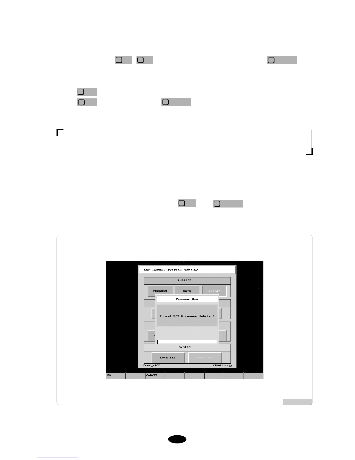
3) Program : Thread Sensing Board Program
<Fig. 3.1.1-3> automatically appears when the operating program and data is installed either via FDD or USB.
This screen can be viewed when selecting ‘THREAD’ in <Fig. 3.0-3>.
T o upgrade the thread sensing board program, press . Press to cancel.
CANCEL
F3
GO
F1
[Fig. 3.1.1-3]
2) Data : It is needed by the embroidery operating program.
Use the direction keys , as in <Fig. 3.0-3> to move to ‘DATA’ and press . Then
<Fig. 3.1.1-2> appears.
To use a floppy diskette for installation, insert the floppy diskette containing the operating program and then
press . To use a USB memory for installation, insert the USB memory into the USB port, and then
press . To cancel installation, press .
CANCEL
F3
USB
F2
FDD
F1
SELECT
F7
F2
F1
[ Caution ]
USB memory's file system should be FAT 16. If it is FAT 32, it cannot be used.

33--44
3.1.2 Backup
Backup is conducted in the opposite direction from installation. For possible loss of data, the operating program
and the data files should be saved in a floppy diskette. If there are no operating program and data files or if the
memory has been formatted, the backup function cannot be used.
1) Program
Use the direction keys , as in <Fig. 3.0-3> to move to ‘PROGRAM’ on the backup menu, and
press . Then <Fig. 3.1.2-1> appears.
To use a floppy diskette for backup, insert an empty floppy diskette and then press . To use a USB
memory for backup, insert the USB memory into the USB port, and then press . To cancel backup,
press .
CANCEL
F3
USB
F2
FDD
F1
SELECT
F7
F2
F1
2) Data
Use the direction keys , as in <Fig. 3.0-3> to move to ‘DATA’ on the backup menu, and press
. Then <Fig. 3.1.2-2> appears.
To use a floppy diskette for backup, insert an empty floppy diskette and then press . To use a USB
memory for backup, insert the USB memory into the USB port, and then press . To cancel the backup,
press .
CANCEL
F3
USB
F2
FDD
F1
SELECT
F7
F2
F1
[Caution]
USB memory's file system should be FAT 16. If it is FAT 32, it cannot be used.
[Fig. 3.1.2-1] [Fig. 3.1.2-2]

33--55
3.1.3 Memory
It has such functions as memory format and memory setting initialization.
1) Format
Use the direction keys , as in <Fig. 3.0-3> to move to ‘FORMAT’ on the memory menu, and
press . Then <Fig. 3.1.3-1> appears.
When pressing , the memory will be formatted, and all programs and data will be deleted. To cancel the
backup, press .
CANCEL
F3
GO
F1
SELECT
F7
F2
F1
2) Setting Initialization
Use the direction keys , as in <Fig. 3.0-3> to move to ‘PARA INIT’ on the memory menu, and
press . Then <Fig. 3.1.3-2> appears.
When pressing , all settings made in the operating program will be initialized. To cancel the
initialization, press .
CANCEL
F3
GO
F1
SELECT
F7
F2
F1
[Fig. 3.1.3-1]
[Fig. 3.1.3-2]

33--66
3) Machine Setting Initialization
Use the direction keys , as in <Fig. 3.0-3> to move to ‘PARA SET’ on the memory menu, and
press . Then <Fig. 3.1.3-3> appears.
When pressing , the machine setting will be initialized, and the screen for machine setting appears. To
cancel, press .
CANCEL
F3
GO
F1
SELECT
F7
F2
F1
[Fig. 3.1.3-3]

33--77
3.1.4 System
The function of entering the lock key is supported.
The embroidery machine operating program has the lock function. When the lock function is set, the operating
program can be used without problem for the set period of time. But when the set time frame passes, the lapse will
occur when opening the operating program. This intentionally causes inconvenience when the program is used after
the set time frame.
If the lock function is enabled, the logo will be displayed as in <Fig. 3.1.4-1>, not as <Fig. 3.0-1>. In case of <Fig.
3.1.4-1>, the operating program can be used without problem for 10 days, and the logo screen will stay for only 2
seconds. However, after 10 days, as in <Fig. 3.1.4-2>, lapse will occur before running the operating program. Time
lapse will also occur when conducting the second batch of embroidery after finishing the first batch of embroidery
work. Likewise after the set time frame, inconvenience occurs when using the operating program.
To resolve the inconvenience, it is required to receive new lock key from the sales agent and enter it to the system.
Otherwise, the time lapse will get lengthened further over the passage of time.
[Fig. 3.1.4-1] [Fig. 3.1.4-2]
[ Caution ]
There are two types of a lock key: limited and unlimited use. For more inquires on the lock key, contact the
distributor’s shop.

33--88
[Example] Re-entry of Lock Key
Press the start switch as in <Fig. 3.1.4-2>.
Then <Fig. 3.0-3> appears.
Use the direction keys , as in <Fig. 3.0-3> to move to ‘Lock Set’ on the system menu.
Press and then <Fig. 3.1.4-3> appears.
Call the distributor’s shop and give it the old code displayed on the user screen as in <Fig. 3.1.4.3>.
(ex : 4 1 0 4 3 2 1 2 3).
The distributor’s shop will give a new lock code.
Use the key pad to enter the new lock code.
Select and press the set key.
OK
F7
SELECT
F7
F2
F1
[Fig. 3.1.4-3]

33--99
3.2.0
Machine Setting Change
The machine setting is the function to conduct the basic specifications setup and adjust the machine settings.
<Fig. 3.2.0-1> appears in either one of the following cases:
1. Memory formatting was conducted and a system was newly installed.
2. Initialization was conducted using the SWF install program (See ‘3.1.3 Memory’).
In the above cases, when the main power switch is turned on, the first screen which appears is <Fig. 3.2.0-1>. On
<Fig. 3.2.0-1>, 12 parameters can be set. When ‘SETTING’ is selected, the screen for selecting the encoder signal
appears.
On <Fig. 3.2.0-1>, to make settings for each item, press the buttons on the right side.
Use , to move to a desired item and press . Then the screen like ‘Fig. 3.2.1
Embroidery Machine Specifications Setting’ appears where the setting of each item is possible. When the setting is
completed for all items, press . <Fig. 3.2.0-2> appears to check the set specifications.
NEXT
F7
SELECT
F7
F2
F1
[Fig. 3.2.0-1] [Fig. 3.2.0-2]

33--1100
3.2.1 Embroidery Machine Specifications Setting
10 specifications can be set.
[Fig. 3.2.1-1] [Fig. 3.2.1-2]
① Head Setting ② Color Count Setting
[Fig. 3.2.1-3]
[Fig. 3.2.1-4]
③ Trimming Method Setting ④ Y-frame Size Setting

33--1111
[Fig. 3.2.1-5] [Fig. 3.2.1-6]
⑤ X-frame Size Setting ⑥ X-space Extension
[Fig. 3.2.1-7] [Fig. 3.2.1-8]
⑦ Wheel Type Select ⑧ Sequin Type Select

33--1122
[Fig. 3.2.1-9] [Fig. 3.2.1-10]
⑨ X Satin Default Setting ⑩ Y Satin Default Setting
[Fig. 3.2.1-11]
⑪ Cording Setting

33--1133
3.2.2 Machine and Signal Setting
Press in <Fig. 3.2.0-1>, and then <Fig. 3.2.2-1> appears.
1) Main Shaft Encoder Signal Setting
Press the select button and set the machine at 100°. While adjusting the encoder, fix the machine when the beep
sound is issued, and ‘On’ is displayed on the screen. Press the select button to conclude the setting.
2) Needle Bar Position Setting
Press the select button and move to the highest number needle bar (ex: 9 color → No. 9). Adjust the potentio
meter, and when the beep sound is issued and ‘On’ is displayed, fix the machine. Press the start button and then
the select button again to conclude the setting.
3) X, Y Limit Setting
Press the select button and manually move the X, Y frame. Check the On/Off status of the sensor and press the
select button to conclude the setting.
4) Wiper Signal Setting
Press the select button and manually move the wiper. When the beep sound is issued, check the abnormality of
the sensor and press the select button again to conclude the setting.
SETTING
F6
[Fig. 3.2.2-1]
[ Warning ]
When the machine setting is wrong, it may cause problem to the machine. Unless there is clear information,
please refrain from changing the default setting.

44--11
<Fig. 4.0-1> is the initial screen of the machine operating program. The screen is composed of (1) embroidery
screen, (2) work information screen, and (3) main function button screen.
4.1
Embroidery Screen
This shows the called embroidery design. When the machine operating program is first installed or when there is no
design called, the SWF logo appears on this screen.
[Fig. 4.0-1] Initial Screen of SWF Machine Operating Programa
4
Operating Program Screen Layout
Embroidery
Screen
Work
Information
Screen
Main Function
Button Screen

44--22
Information Description
Remarks
- # : Design name/memory saving number
- ST . : Total number of stitches of a selected design
This shows all information related to the currently called design.
- X, Y length from the design starting position (central line)
- X, Y length of the selected design (unit: mm)
- Number of colors used for the selected design
- Number of jumps for the selected design
- P: reverse effect (X, Y, XY reverse)
- 0 ANG: rotation shape according to the angle of the selected design
- X 100%: value for X enlargement
- Y 100%: value for Y enlargement
- Current needle bar / next needle bar
- Frame’s return to the origin
※ As in ‘5.4.2 EMB Parameter Setting’, when ‘3) Auto Origin Return’
is selected, it is green. When ‘No’ is selected, it is gray.
- shaft’ s stop position. Either in the middle of embroidery or when it is
not 100°, its color gets gray.
※ [Warning] When changing the needle bar, its angle must be 100°.
- Time taken so far for embroidery (hh:mm)
- ST : Accumulative number of stitches made so far
- WK : Number of work finished. Whenever a work is finished, the
figure increases by one.
- X : Current X-shaft position
- Y : Current Y-shaft position
- ST: Number of stitches made so far
- %: Progress of stitching in %
- Set embroidery speed
- Current embroidery speed
- Frame moving speed : low / mid / high
4.2
Work Information Screen
44--33
4.3
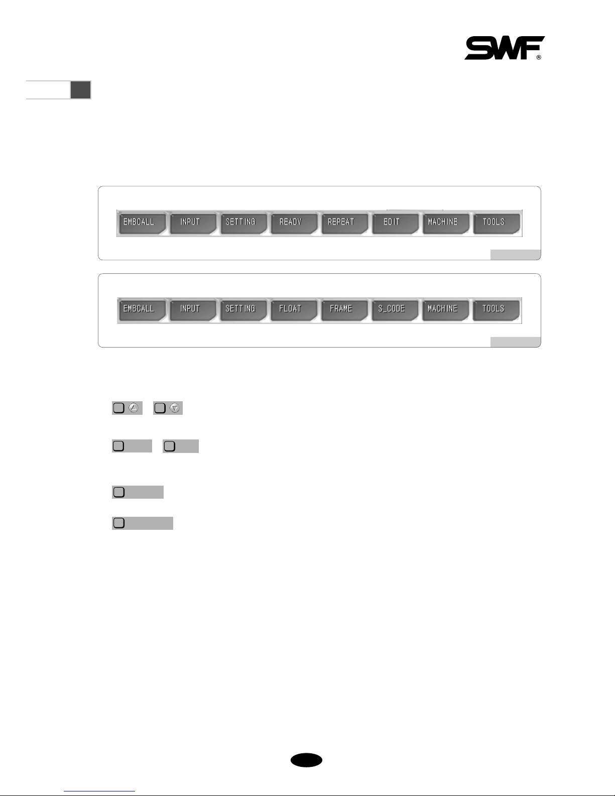
Function Menu Button Screen
There are eight menus related to embroidery work. When each button is pressed, related sub-menu appears.
Depending on whether the machine is in operation, there are two types of menu buttons including ‘Function menus
before embroidery begins’ as in <Fig. 4.3-1> and the ‘Function menus during the pause of embroidery work’ as in
<Fig. 4.3-2>. More details will be dealt with in the section of each button.
[Fig. 4.3-1]
[Fig. 4.3-2]
◆ Frequently Used Buttons on Menu (the number assigned to a key could be different on each screen)
, :
When selecting a menu, they are used to move to the desired menu for selection.
, : If there are more menus which cannot be displayed in one screen, they are used to
move to the previous or next screens.
: It is used to select a menu or execute a command.
:
The command which is going to be executed can be closed.
The window where the command was executed can be closed.
The command can be cancelled.
The move to the prior execution screen is possible.
PREVIOUS
F8
SELECT
F7
>>
F4
<<
F3
F2
F1

44--44
4.4.0
Work Progress Message and Clock
There are the message window at the bottom of <Fig. 4.4.0-1> and the clock window at the right top of the screen.
The message window displays the embroidery information in progress. The clock window displays the time.
4.4.1 Work Progress Messages
[Fig. 4.4.0-1]
Message Situation
“Stop by the stop switch”
“Stop by detecting the upper thread break”
“Stop due to color code and stop code”
“Stop due to the detection of the frame outside the limit”
“Design close”
“Stop by the back stitch”
“Frame feed under way”
“Stop the frame feed”
“Offset position stop”
“Needle bar replacement”
“Choice of the feed unit during the non-stitching operation”
“Start switch → machine operation”
“Design data loading under way”
When the stop switch is pressed
When the machine is stopped after the thread break is sensed
When the machine is stopped due to the stop code
When the frame moves beyond the set motion limit
When the embroidery work is finished
When the machine is stopped after the back stitch
When the frame is in motion
When the frame is stopped in the middle of feeding
When the machine is stopped at the offset position
When the needle bar is replaced
When the non-stitching operation is conducted
When a test is conducted in the test mode
When embroidery designs are called
44--55
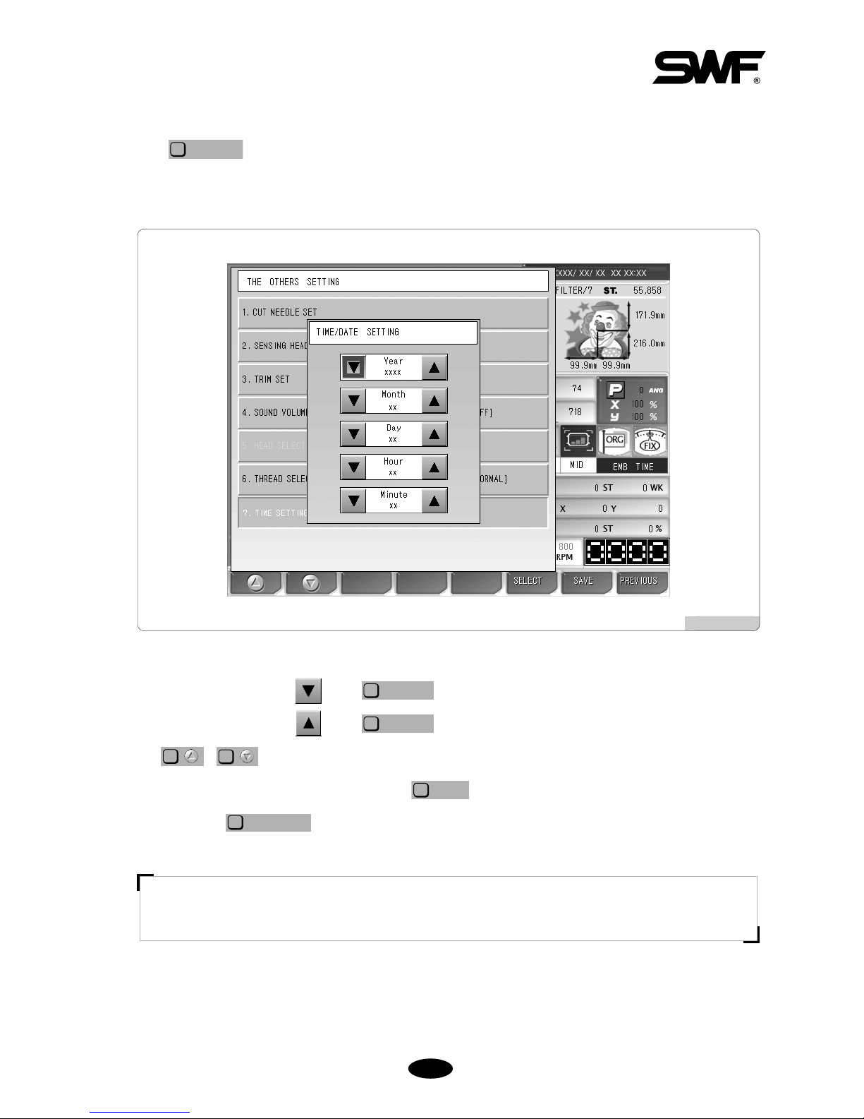
4.4.2 Date and Time Change
Press to change time or date displayed at the right top of the screen, and select ‘7. TIME SETTING’.
When the menu is selected, the date and time setting is possible as in <Fig. 4.4.2-1>.
SETTING
F3
When the cursor is located at , press to reduce the figures for date and time.
When the cursor is located at , press to increase the figures for date and time.
Use , to move around the menu.
When the date and time setting is completed, press for application.
T o cancel, press .
PREVIOUS
F8
SAVE
F6
F2
F1
SELECT
F6
SELECT
F6
[ Note ]
If the lock is set up, the date and time setting cannot be made.
[Fig. 4.4.2-1]

55--11
Prior to embroidery work, various settings should be made. In particular, when the machine operating program is
installed, various parameters should be set including design call. Of course, there is no problem in conducting
embroidery in default setting. Nevertheless, it would be better for you to learn more about the functions of the
program to produce better quality embroidery.
Basically, use ~ on the OP Box to use functions. Press each key corresponding to each function menu.
5
Function Menu Before Embroidery Begins
EMBCALL
F1
INPUT
F2
SETTING
F3
READY
F4
REPEAT
F5
EDIT
F6
MACHINE
F7
F1
G
F1

55--22
5.1
Structure of the Menu Before Embroidery Begins
★Design Call
Input
Setting
Ready
Repeat
★Edit
Machine
Tools
Design
FDD Input
USB
CF Card
Serial
★Basic Setting
Embroidery Parameter Setting
Machine Parameter Setting
Needle Setting
★Frame Offset Setting
Option Setting
The Others Settings
Position
★Gauge
★Exclude
Fastview
Trace
General Repeat
Special Repeat
Repeat Load
Stitch Edit
Design Divide
Design Filtering
Design Zoom In
Machine Service
Machine Information
Machine Test
Frame Origin
Error Information
Thread Break Information
Memory Initial
Origin
Holding
Needle DN
Needle UP
Language
Sequin Lift
Sequin Feed
Trim
Delete
Copy
Output
Export
Format
Select
Needle Select
Needle Convert
Needle Color
Cut Needle Set
Sensing Head Set
Trim Set
Sound Volume
Head Select
Thread Select
Time Setting
Jump Test
Wiper Test
Picker Test
Trim Test
Holding Test
Thread Sensing Test
Preview
Delete
Copy
※ [ Caution ] : The functions marked with ‘★’ cannot be used during the repeat work.

55--33
5.2
Design Call
- This function is to call back the embroidery designs saved in the memory. The function
can be used to copy and delete designs or export them to the external devices.
<Fig. 5.2-1> is the screen where no designs are stored in the memory or there is no design called out. If there is a
design called out previously, the previous work’s design is displayed as in <Fig. 5.2-2>.
If there are no designs called as in <Fig. 5.2-1>, several function buttons cannot be used. The buttons whose letters
are pale cannot be used until the designs are called later.
If is pressed on the screen as in <Fig. 5.2-2>, embroidery designs stored in the memory appear as
in <Fig. 5.2-3>. Up to 100 designs can be stored in the memory. Up to 20 designs can be displayed on one screen.
Let’s get to know more about embroidery design call through [Exercise 5.2-1].
EMBCALL
F1
[Fig. 5.2-1]
[Fig. 5.2-2]

55--44
[Exercise 5.2-1] Call the design from #35 Room.
Press .
When the design call button is pressed, the designs stored at each room are displayed as in <Fig. 5.2-3>. The
screen displays the room numbers and embroidery designs. Each screen shows up to 20 designs. The design we
would like to call is located at the #35 room, so we have to move to the next screen. Press to move
to the next screen.
>>
F6
EMBCALL
F1
Use , , , to move to the screen where #35 room is displayed.
As in <Fig. 5.2-4> below, 20 designs are displayed.
F2F2F2
F1
[ Note ]
The number of stitches unused indicates the memory space currently unused.
[Fig. 5.2-3]
[Fig. 5.2-4]

55--55
Go to # 35 room in <Fig. 5.2-4> and press . (the square room with slashes)
Then a new window appears as in <Fig. 5.2-5>. On the left-hand side, the chosen design is displayed. On the
right-hand side of the screen, the information on the design is displayed. On the screen, such buttons as
, , , are enabled.
SELECT
F4
EXPORT
F3
COPY
F2
DELETE
F1
SELECT
F7
Press .
The selected embroidery design will be called and displayed on the initial screen as in <Fig. 5.2-6>.
SELECT
F4
[ Note ]
On the embroidery information section, “OPTION NORMAL”might be seen. “Normal”refers to common embroidery
data. Sometimes, “Sequin”might be displayed. It means that it is the embroidery design including the sequin code.
[Fig. 5.2-5]
[Fig. 5.2-6]

55--66
[Exercise 5.2-2] Copy the design from #35 Room to #69 Room.
Repeat ~ of [Exercise 5.2-1] from “Call the design”from #35 Room.
Press in <Fig. 5.2-5>.
As in <Fig. 5.2-7>, message windows will appear, and the empty room numbers and the up/down, copy, and
cancel buttons are displayed. Empty rooms are the space where new embroidery data can be saved. It is possible
to move to the target room number by using , .
Use , to move to #69 Room and press .
COPY
F7
F2
F1F2F1
COPY
F2
[ Note ]
If it is desired to cancel the copy, press .
PREVIOUS
F8
The embroidery data in #35 Room was copied in #69 Room. As in <Fig. 5.2-8>, the design was moved to
#69 Room.
[Fig. 5.2-7]
[Fig. 5.2-8]

55--77
[Exercise 5.2-3] Delete the design in #69 Room.
Repeat ~ of [Exercise 5.2-1] “Call the design from #35 Room”.
Use the direction keys to go to #69 Room and press .
Press in <Fig. 5.2-5>.
As in <Fig. 5.2-9>, the message window appears asking “Do you want to delete?”
DELETE
F1
SELECT
F7
[ Note ]
If you do not want to delete it, press .
PREVIOUS
F8
Press .
When compared with <Fig. 5.2-8>, the design in #69 Room was deleted as in <Fig. 5.2-10>. #69 Room
becomes available for design storage.
YES
F1
[Fig. 5.2-9]
[Fig. 5.2-10]

55--88
[Exercise 5.2-4] Copy the design of #35 Room using floppy diskette or USB.
Repeat ①~③ of [Exercise 5.2-1] “Call the design from #35 Room.”
Insert a floppy diskette into the floppy drive or a USB memory into the USB port.
Press in <Fig. 5.2-5>.
As in <Fig. 5.2-11>, the message window appears asking for selecting the output device. If is
pressed, the design will be saved in the floppy diskette. If is pressed, the design will be saved in the
USB memory.
USB
F2
FDD
F1
EXPORT
F3
[ Caution ]
If a floppy diskette is removed from the disk drive while being used, the data in the diskette might be deleted
or the diskette itself can be damaged.
[ Caution ]
The file system of the USB memory shall be FAT16, not FAT32.
[Fig. 5.2-11]

55--99
Press or .
The message asking for the saving method appears as in <Fig. 5.2-12>. If is pressed, it is saved in
the floppy diskette in the SWF method. If is pressed, it is saved in the Tajima method.
T—CODE
F2
SWF
F1
USB
F2
FDD
F1
Press .
The green bar at the bottom of the message shows the progress as in <Fig. 5.2-13>. When the copy is
completed, the entire bar becomes green.
SWF
F1
[Fig. 5.2-12]
[Fig. 5.2-13]

55--1100
<Fig. 5.2-14> shows the status of the floppy diskette where the design was copied.
To check the status, see 5.3.0) Input - “FDD Input”. When saving designs in a floppy diskette, the file is saved
as SWF000.SST. The names of files copied to a floppy diskette include SWF000.SST, SWF001.SST. or
SWF000.DST , SWF001.DST, etc.
[Fig. 5.2-14]

55--1111
[Fig. 5.3.0-1]
5.3.0
Input/Output
- This function is to enter designs from external devices to the OP Box. The designs can be
copied from such external devices as a floppy diskette, USB memory, CF (Compact Flash)
card, and serial communications.
On the initial screen, press and the sub-menu appears as in <Fig. 5.3.0-1>. The sub-menu buttons
include Floppy Diskette, USB, CF Card, and Serial.
INPUT
F2

55--1122
5.3.1 FDD Input
When the Floppy Diskette button is pressed, the brief information on the designs saved in the floppy diskette is
displayed. Diskette formatting, design preview, design input, and design deletion can be performed.
Insert the floppy diskette containing embroidery design files into FDD.
Select “Floppy”in <Fig. 5.3.0-1>, and <Fig. 5.3.1-1> appears on the screen.
Up to 10 designs can be displayed on one screen. If the total number of designs saved is over 10, scroll bar and
scroll up/down buttons can be used to see next screens. Such information as file name, total # of stitches, and
creation date is displayed for each design. As in <Fig. 5.3.1-1>, use , and select #63 Room
and press . Then <Fig. 5.3.1-3> appears, and such functions as preview, delete, and
copy can be performed.
SELECT
F7
F2
F1
[ Caution ]
If a floppy diskette is removed from the disk drive while being used, the data in the diskette might be deleted
or the diskette itself can be damaged.
[Fig. 5.3.1-1]

55--1133
[Exercise 5.3.1-1] Conduct the design preview for ““63.SST””saved in the floppy diskette
and copy it in #12 Room.
In <Fig. 5.3.1-2>, select and press .
Then, the window appears as in <Fig. 5.3.1-3>.
SELECT
F7
[Fig. 5.3.1-2] [Fig. 5.3.1-3]
Select the room number.
Use the Room Up/Down buttons , to select the room number. When the buttons are pressed,
the empty rooms are displayed in order. Select #12 Room.
F2
F1
Press .
As in <Fig. 5.3.1-4>, the design is displayed on the pre-view window.
PREVIEW
F1
[Fig. 5.3.1-4]

55--1144
Press .
As in <Fig. 5.3.1-5>, the status bar at the bottom of the window turns green, showing the copying progress.
When the bar is completely green, it means that copy is finished, and the window disappears.
COPY
F3
As in <Fig. 5.3.1-6>, the design copied in #12 Room can be checked. To check the design copied, see “5.2 Design
Call”.
[Fig. 5.3.1-5]
[Fig. 5.3.1-6]

55--1155
[Exercise 5.3.1-2] Delete ““63.SST””in a floppy diskette.
Select as in <Fig. 5.3.1-2> and press .
Press .
Then, <Fig. 5.3.1-7> appears. The message asking “Do you want to delete?”appears on the screen. If you want
to delete it, press . If you do not want to delete it, press .
NO
F2
YES
F1
DELETE
F2
SELECT
F7
Press .
As in <Fig. 5.3.1-8>, the files are deleted.
YES
F1
[Fig. 5.3.1-7]
[Fig. 5.3.1-8]

55--1166
[Exercise 5.3.1-3] Floppy Diskette Format
Press the format button as in <Fig. 5.3.1-1>.
[ Caution ]
If a floppy diskette is removed from the disk drive while being used, the data in the diskette might be deleted
or the diskette itself can be damaged.

55--1177
You can move to the embroidery design folder by pressing , as in <Fig. 5.3.2-1>.
When pressing , as in <Fig. 5.3.2-2>, the design files contained in the chosen folder are displayed.
T o move to the upper -level folder, press the “”folder on the left-hand side.
DIR/FILE
F3
F2
F1
[Fig. 5.3.2-2]
5.3.2 USB Input
This function is to enter embroidery designs saved in the USB memory to the OP Box.
Insert the USB memory containing embroidery design files into the USB port.
When “USB”is selected in <Fig. 5.3.0-1>, <Fig. 5.3.2-1> appears.
[ Caution ]
The file system of the USB memory shall be FAT16, not FAT32.
[Fig. 5.3.2-1]

55--1188
When a design is selected in <Fig. 5.3.2-2>, <Fig. 5.3.2-3> appears.
When a USB memory is used, the preview function is directly performed. Input and Delete function keys appear at
the bottom. Preview, Delete, and Copy function can be used in the same way as in “5.3.1 FDD Input”.
[Fig. 5.3.2-3]

55--1199
5.3.3 CF Card Input
This function is to import the embroidery design files saved in the C/F card to the OP Box.
Connect a C/F card containing embroidery design files to the C/F card reader and insert the USB plug of the C/F
card reader into the USB port of the OP Box.
When “C/F Card”is chosen in <Fig. 5.3.0-1>, <Fig. 5.3.3-1> appears.
Use , in <Fig. 5.3.3-1> to move to the folder which has embroidery designs.
When is pressed, the design files in the chosen folder are displayed as in <Fig. 5.3.3-2>.
T o move to the upper -level folder, select the “”folder on the left-hand side.
DIR/FILE
F3
F2
F1
[Fig. 5.3.3-1]
[Fig. 5.3.3-2]

55--2200
When a design is chosen in <Fig. 5.3.3-2>, <Fig. 5.3.3-3> appears.
In the USB memory, the preview function can be directly performed. Copy and Delete buttons also exist at the
bottom. Preview, Delete, and Copy functions can be used in the same way as explained in “5.3.1 FDD Input”.
[Fig. 5.3.3-3]

55--2211
5.3.4 Serial Input
This function is to import embroidery designs from embroidery design program Wings to
the OP Box.
Use the serial cable to connect to the OP Box. Call embroidery designs from Wings after establishing the
connection. When the screen appears, press “File”on the menu and select “Export”on the file menu. When
selecting “Other”on the export menu, the Export Output window appears. If driver has not been installed, press
“Add Driver.”When the “Add Wings I/O Driver”window appears, open the Sunstar.wio file, the Sunstar-
dedicated driver. Select the driver newly added to the Design Output window and press OK. Select the desired
format and press OK.
While designs are exported from the Wings program, select “Serial”in <Fig. 5.3.0-1> and then <Fig. 5.3.4-1>
appears. Preview and Delete functions cannot be used. Select a room number by using , and
press . Then <Fig. 5.3.4-2> appears.
COPY
F3
F2
F1
[Fig. 5.3.4-1]

55--2222
T o check the designs copied after design loading, see “5.2 Design Call”.
[Fig. 5.3.4-2]

55--2233
[Fig. 5.4.0-1]
•Basic setting: Sets zoom-out, zoom-in, and angle.
•EMB parameter setting : Sets parameters related to embroidery .
•M/C parameter setting: Sets parameters related to machine.
•Needle setting: Selects or changes the needle bar .
•Frame offset setting: Designates the off-set point on designs.
•Options setting: Sets option devices such as coding and boring.
•The Others Settings: Determine needle type and set thread sensing.
5.4.0
Setting
- On the setting menu, overall setups regarding embroidery can be made. There are seven
sub-menus under the setting menu, which include basic setting, embroidery parameter,
machine parameter, needle bar , prime of fset, options, and other settings.
On the initial screen, press among main function buttons, and <Fig. 5.4.0-1> appears.
SETTING
F3

55--2244
※ Setting Tips
To conduct basic, embroidery parameter, machine parameter, frame off-set, and options setting, press each
button, and? <Fig. 5.4.0-2> appears to enter values for setting.
- <Fig. 5.4.0-2> is the screen where X scale can be set using the basic setting.
- On the very top, there is title “X Scale”and the line below displays the setting scope of X Scale in red print.
- The next line is the space to enter a desired value.
- Use the number buttons to enter a desired value
- Press to correct the entered value.
- Press to apply the entered value.
- Press to cancel the entered value.
PREVIOUS
F8
[Fig. 5.4.0-2]
Item
Scope
Value

55--2255
5.4.1 Basic Setting
Press the basic setting button in <Fig. 5.4.0-1>, and the nine basic settings appear on the screen as in <Fig. 5.4.1-1>.
Press , to see the next menu.
When is pressed, the existing setting becomes initialized.
Press to select a menu. If the setting exit is desired, press .
PREVIOUS
F8
SELECT
F7
DEFAULT
F3
F2
F1
[Fig. 5.4.1-1]

55--2266
① X Scale
Enlarges or reduces a design in the X-axis direction.
The default is 100%, and the value can be adjusted from 50% to 200% by the unit of 1% .
② Y Scale
Enlarges or reduces a design in the Y-axis direction.
The default is 100%, and the value can be adjusted from 50% to 200% by the unit of 1% .
< 100% > < Y-axis 200% >
< 100% > < X-axis 200% >
< 100% >
< Enlarge Both X and Y >
< X, Y-axis 200% >

55--2277
③ Angle
Turns around the embroidery design according to the rotation angle value set.
The default is 0°, and the value can be adjusted from 0°to 359°by the unit of 1°.
④ Mirror
Reverses a design based on X, Y, or X,Y axes.
The default is “0”or “normal work”.
< 0°> < 90°>
< No > < X-axis >
< No > < Y-axis >
< No > < X_Y-axis >
Value Description
0 Basic Setting
1 X-axis reverse
2 Y-axis reverse
3 X, Y -axis reverse

55--2288
⑤ X Satin
In case where the embroidery design is a satin stitch, this function can set the satin width.
This function determines the satin stitch length in the X-axis direction. The value can be
increased by the unit of 0.1mm.
⑥ Y Satin
This function sets the Y-axis satin width.
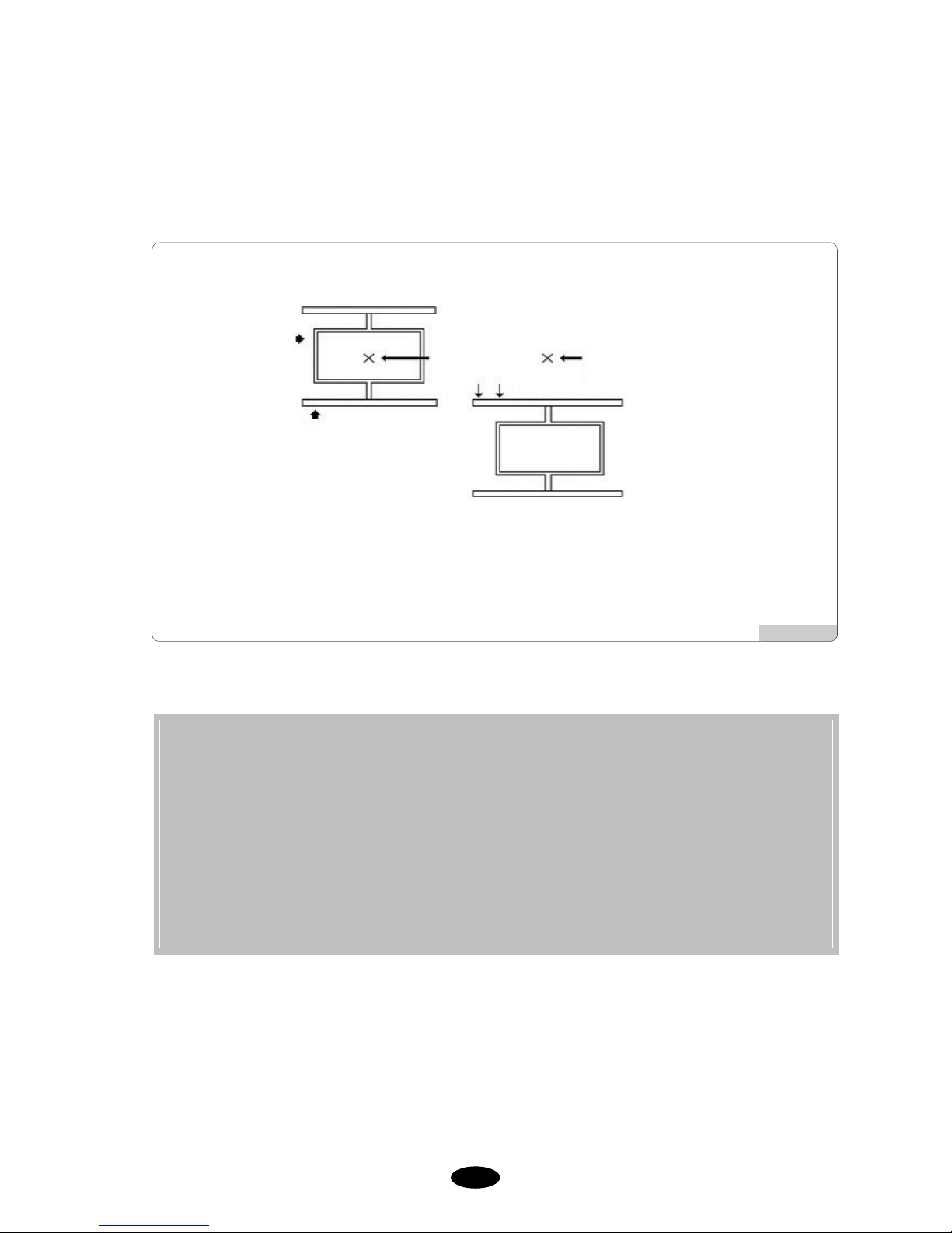
⑦ Start stitch
This function sets the starting stitch number for the embroidery design to be worked. It enables skipping as
many as stitches desired for embroidery work.
For instance, there is a design with a total of 10,000 stitches below. The design on the left side has entire
stitches embroidered. On the right side, the design has only 5,000 stitches since the starting stitch number
was set at 5,000.
[Fig. 5.4.1-4]
Start Point
Start
Point
Finish
Point
Finish
Point
The embroidery
skipped part
(5,000 stitches)
Basic Design
(a total of 10,000 stitches)
When the number of
starting stitch is set at 5,000
[Fig. 5.4.1-3][Fig. 5.4.1-2]
55--2299
⑧ Offset Function
This function determines whether to use the automatically designated off-set function or not.
[Fig. 5.4.1-5]
★ Setting Tips to Use Frame Offset Work Function
1. Select “Yes”for the question asking the frame coordinates setting in the basic setting situation.?
2. Go to “Setting”→“Frame Offset Setting”and determine the starting position, the offset middle
position, and the stop position after design completion (offset) (5.4.5 Frame Offset Setting)
3. To use the offset function during embroidery work, go to “Main Function Menu”→“Setting”→
“5.4.5 Frame Offset Setting,”and enter the desired value to “Frame Offset Position”.
※ The above three settings shall be made to carry out the frame offset work.
Embroidery
Starting Point
<Embroidery Begins> <Embroidery Is Finished>
Frame Move
Needle Bar Position After
Embroidery Is Completed
Frame
Frame

55--3300
⑨ Jump Convert
This function is to move the frame after trimming, in the case where repeat jumps take place and they occur
more than the set value.
For instance, let’s assume that the set value is 5. Then, the machine conducts jump stitches without trimming
until 4 stitches. If the repeat jump with over 5 stitches is found, conduct trimming first and move 5 stitches
back and start embroidery again. The default is 3 stitches and the value can be adjusted from 0 to 10 by the
unit of 1 stitch.
[Fig. 5.4.1-6] “Trimming by Jump Frequency”When Value is 5
[ Caution ]
If ‘0[st]’is chosen, when repeat jump takes place, there will be no trimming regardless of the number of
stitches for the number of repeat jump.
When the value is 4 [stitches]
When the value is 5 [stitches]
(The thread is linked to the next design without trimming)
(The thread moves to the next design after trimming)

55--3311
[Fig. 5.4.2-1] [Fig. 5.4.2-2]
[Fig. 5.4.2-3]
5.4.2 EMB Parameter Setting
<Fig. 5.4.2-1>, <Fig. 5.4.2-2>, and <Fig. 5.4.2-3> are the screens showing the parameter setting. For setting, use
the number keys to enter the desired values within the scope same as the basic setting.?
Press , to view the next menu.
turns back the set values to default values of the operating program.
When is pressed, the next menu is displayed.
<Fig. 5.4.2-1>, the initial screen, shows eight setting menus. When is pressed first, the following eight
setting menus appear as in <Fig. 5.4.2-2>. Press again and the last embroidery parameter setting menus
appear as in <Fig. 5.4.2-3>. When is pressed once again, the initial screen returns as in <Fig. 5.4.2-1>.
is used to select menu. Press to exit from setting.
PREVIOUS
F8
SELECT
F7
NEXT
F4
NEXT
F4
NEXT
F4
NEXT
F4
DEFAULT
F3
F2
F1

55--3322
① T otal Stitch Clean
“ ST” as in “4.2.0 Work Information Screen” is the function to accumulate the total number of stitches
worked so far from the beginning of machine use or from the information initialization. This function
initializes the total stitch number into zero.
② T otal W ork Clear
“ WK” as in “4.2.0 Work Information Screen” is the function to accumulate the total number of
embroidery works produced so far from the beginning of machine use or from the information initialization.
This function initializes the total work number into zero.
(When initialization is desired, press “0” and then press . If initialization is not desired, press .)
③ Auto Origin Return
This function makes the frame return to the origin after embroidery work is completed.
- The default is “Yes (1)”. If the return to the origin is not desired, enter “No (0)”.
④ Jump Change Data
This function sets the needle width to change the regular code to the jump code.
- The default is 8.0 mm, and the scope of adjustment is from 5.0 to 12.7 mm and it can be set by the unit of
0.1 mm. For instance, if the distance between two needles is longer than the set value when the frame
moves from one needle to the other needle, it becomes a jump stitch.
⑤ Auto Backtack
The function sets the bartack performance to create stitch for embroidery beginning (thread release
prevention).
- The default is “EndBack” It can be changed to “No(0”), “Start Bartack(1)”, “End Bartack(2)”, and
“All(3)”.
⑥ Jump Convert (Length)
If the total stitch length of the repeat jump code is above the set value, trimming is primarily performed
before carrying out the next work. This function can set the maximum jump stitch length.
- The default is “No.” The scope of adjustment is from 1mm to 50mm by the unit of 1mm.
⑦ Applique
This function is used to set up the needle bar. If the needle bar is repeatly entered for needle bar setting, and
applique is “Yes”, the machine automatically stops without trimming when the needle bars overlap.
- The default is “Yes.”

55--3333
⑧ Auto Back Stitch
When thread break is sensed, this function sets the number of backward stitches.
- The default is 0 and the scope of adjustment is from 0 to 5 by the unit of 1 stitch.
⑨ Auto Start After Trimming
The function sets up whether embroidery automatically begins after jump code and trimming or trimming by
suspension code.
- The default is “Yes.” If automatic start is not desired, enter “0” to choose “No.”
⑩ Auto Start After Frame Back
The function is to determine whether the machine is automatically started when the frame reaches “⑫ All
Needle Bars’ Starting Position After Back Stitching.”
- The default is “Yes.” If automatic start is not desired, enter “0” to choose “No.”
⑪ All Head Swing After Stitch Back
The function is to decide whether the heads with broken thread are operated only or whether the needle bars
of all heads are operated in case where the frame is moved backward from the machine stop point, and the
embroidery work is begun with the bar switch.
- The default is “single.” To operate the needle bars of all heads, press “0” to select “All.”
⑫ All Head Startpoint After F .B
When all or multiple needle bars are simultaneously in operation and the machine is stopped due to the
detection of a problem (thread break) affecting one needle bar, it is possible to conduct the back-stitching for
the concerned needle bar with the problem to correct the part where stitching did not occur. After that, if all
the needle bars are operated from the point which is located before the problem area, the embroidery will be
overlapped on the problem area, making correction. The function is to set the relative position of the entire
needle bar motion, and the value can be set at the range from 1 to 20[st]. The default is 2[st].
⑬ Frame Forward / Back Moving Unit
This function is to set the number of stitches to move by the one-time operation of the bar switch when the
frame is moved forward and backward with the bar switch.
- The default is 1[st]. It can be set at the range of 1 to 10[st] by the unit of 1[st].
⑭ Optimize Method
The part where embroidery is conducted in the form of running stitch in a certain distance away from the
outline is called a gauge. This function is to set the distance between gauge and outline.
- The default is 10[mm], and the setting range is from 1 to 30[mm].

55--3344
⑮ Software Limit Setting
This function is to set whether to use the virtual frame limit setting function.
- The default is “No.”
⒃ Thread Break Moving
This function is to set the length of automatic backward movement of the frame in case where the machine is
stopped due to the sensing of thread break in order to make the upper thread placement much easier.
- The default is 0[mm], and the setting range is from 0 to 50mm. The value can be set by the unit of 1[mm].
⒔ Lock Stitch
This function is to set the execution of multiple backtacks to prevent thread release upon trimming.
- The default value is 1 stitch, and the value can be set at the odd number within the range of 1 to 5 stitches.
⒕ Auto Start After Color Change
When the thread color change code appears during embroidery, change the needle bar according to the needle
bar setting. This function is to determine whether embroidery is automatically started after the needle bar
change.
- The default value is “Yes (1).”

55--3355
5.4.3 M/C Parameter Setting
<Fig. 5.4.3-1>, <Fig. 5.4.3-2> and <Fig. 5.4.3-3> are the screens showing machine parameter setting. As with the
basic setting, use the number buttons and enter the desired value within the permissible range.
Press , to view the next menu.
changes the saved settings to default values.
Press to move to the next page.
<Fig. 5.4.3-1> shows eight setting menus on the first screen. When is pressed, as in <Fig. 5.4.3-2>, the
next eight setting menus appear. When is pressed again, as in <Fig. 5.4.3-3>, the last setting menu
appears. When is pressed, as in <Fig.5.4.3-1>, the initial screen appears.
Press to select menus and press to exit from setting.
PREVIOUS
F8
SELECT
F7
NEXT
F4
NEXT
F4
NEXT
F4
NEXT
F4
DEFAULT
F3
F2
F1
[Fig. 5.4.3-1] [Fig. 5.4.3-2]
[Fig. 5.4.3-3]

55--3366
① Max. speed
This function sets the maximum embroidery speed.
– SB Series Embroidery Machine: The default value is 1200[rpm], and the speed can be adjusted from the
minimum speed to 1200[rpm] by 10[rpm] each time.
– Multi-head E-Series Embroidery Machine: The default is 900[rpm], and the speed can be adjusted from
the minimum speed to 1200[rpm] by 10[rpm] each time.
– DM Series Embroidery Machine: The default is 1500[rpm], and the speed can be adjusted from the
minimum speed to 1500[rpm] by 10[rpm] each time.
② Min. speed
This function sets the minimum embroidery speed.
– The default is 300[rpm], and the value can be adjusted at the range from 300 [rpm] to the maximum
speed by the unit of 10[rpm].
③ EMB speed
This function sets the embroidery speed.
– The default is 800[rpm], and the value can be adjusted at the range from the maximum speed to the
minimum speed by the unit of 10[rpm].
④ Inching speed
This function sets the starting speed for embroidery work.
– The default is 100[rpm], and the value can be adjusted at the range from 50[rpm] to 200[rpm] by the unit
of 10[rpm].
⑤ Jump speed
This function sets the range of the jump stitch speed, which is characterized by frame move without sewing.
– The default is 1000[rpm], and the value can be adjusted at the range from 300[rpm] to 1000[rpm] by the
unit of 10[rpm].
⑥ Slow Speed
This function sets the embroidery speed during slow operation.
– The default is 650[rpm], and the value can be adjusted at the range from the minimum speed to the
maximum speed by the range of 10[rpm].
⑦ After Trimming Inching Stitch
When the color change signal is issued or when embroidery work for one design is completed, the closing is
conducted. At this time, the function sets the number of stitches to be made during slow operation.
– The default is 3 stitches, and the value can be adjusted at the range from 2 to 10 stitches by the unit of 1.
⑧ Auto Trimming
This function is to enable the automatic trimming function.
– The default is “Yes”, and to turn off the automatic trimming function, choose “No”.

55--3377
⑨ Auto Color Change
This function is to enable the automatic color change function.
– The default is “Yes”, and to turn off the automatic color change function, choose “No.”
⑩ Bottom Dead Point Stop
This function is to enable the needle bat to stop at the lowest point when the embroidery work is completed.
– The default is “No,” and select “Yes (1)” to make the needle bar stop at the lowest stop position.
⑪ Frame Setting
This is to set the types of embroidery frame.
⑫ Frame Speed Setting
This is to set the frame move speed during frame feeding, such as automatic return to origin and offset move.
– The default is “High Speed(1)”. To set the low speed, enter “Low Speed (0)”.
⑬ Frame Move Method (Trimming)
This is to shake the frame left or right to separate the thread from embroidery materials
after trimming.
– The default is X(1). To set the move direction along the Y-axis direction, select Y(2). If no direction is
selected, choose “NO(0)”.
⑭ Inching stitch
When starting embroidery, the machine starts operation at the inching speed. This function is to set the
number of stitches to be made during inching operation.
– The default is 2 stitches, and the value can be adjusted at the range from 2 to 10 stitches by the unit of 1
stitch.
⑮ Needle Move Function (Offset)
This function is to lift the needle bar by activating the jump motor when it moves to the offset position.
– The default is Yes(1), and when the function is unnecessary, select No(0).
⒃ Power On Auto Origin
This function is to automatically find the origin after the power is on.
– The default is “No”. If “Yes” is chosen, but the origin setting is wrong or the machine develops problems,
all settings shall be initialized. For setting initialization, see “2) Program setting Initialization of 3.1.3
Memory”.

55--3388
⒔ Start / End Filter
This function is to prevent thread break by conducting automatic filtering for the stitch of 0.5mm or shorter,
when starting or closing embroidery.
– The default is 0.0[mm], and the value can be adjusted from 0.0[mm] to 0.5[mm] by the unit of 0.1[mm].
⒕ Speed Switching Data
When the stitch value becomes higher than the set value, the embroidery speed is slowed down. It sets the
width of a stitch.
– The default is 4.0[mm]. The value can be set at the range of 3.0[mm] ~6.0[mm] by the unit of 1.0[mm].
⒖ Thread Break Sensor
If the sensor detects the repeat breaks of the upper thread at the set length, the machine will stop its
operation. This is to prevent false detection associated with sensor’s malfunction.
– The default is 3[st], and under this setting, the thread sensor does not work. The value can be adjusted
from 0 to 10[st] by the unit of 1[st].
⒗ Thread Break Method
This function is to set the sensitivity of the sensor when it detects thread.
– The default is Low(0), and the other options to choose include High(2) and Medium(1).
Thread Length Trimmed
Frame Start Angle For “A” Area
When the embroidery width is 1.9mm or below, this function sets the rotation angle of the main shaft when
the frame starts moving.
– The default is 240。, and the value can be adjusted from 230。to 250。by the unit of 1。.
Frame Start Angle For “B” Area
When the embroidery width is 2.0mm or above, this function sets the rotation angle of the main shaft when
the frame starts moving.
– The default is 240。, and the value can be adjusted from 230。to 250。by the unit of 1。.
Picker Off Time (Trimming)
This function is to set the length of the remaining upper thread at the needle when automatic trimming is
conducted.
– The default is 13[ang]. If the value set is smaller than the default, the remaining upper thread will be
short, and vice versa. The value can be adjusted from 0 to 60[ang] by the unit of 1[ang].

55--3399
5.4.4 Needle setting (color)
This function is to enable automatic change of needle bars when the thread color change code appears. It is also
able to change the colors of the embroidery design displayed on the screen.
<Fig. 5.4.4-1> and <Fig. 5.4.0-1> appears when the needle bar setting button is pressed to set the needle bars. The
needle bar setting can be divided into three steps including needle bar selection, change, and color change.
■To understand the above, let’s look at the head section of the SWF multi-head embroidery machine as
in <Fig. 5.4.4-2>.
As in <Fig. 5.4.4-2>, the multi-head embroidery machine has needle bars for each of which unique number is
designated. Each number is matched one or one to the standard needle bar on the “Needle Bar Number Change
Menu” as in <Fig. 5.4.4-1>. If the standard needle bar and the changed needle bar are same, the needle bar with a
unique number on the head section as in <Fig. 5.4.4-2> will operate. The unique numbers can be virtually changed
by pressing the change button. Here is an example for clearer understanding.
•Select: This is the menu where the order of changing needle bars is set when the color change code appears
during embroidery. Up to 300 color change codes can be applied.
•Change: This enables the user to change the 1 or 1 match between the needle bar table and the needle bar
at the his/her discretion.
•Color change: This function is to change the colors of each needle bar.
[Fig. 5.4.4-1] [Fig. 5.4.4-2]

55--4400
(1) Needle select
This function is to determine the changing order of needle bars when the color change signal appears during
embroidery. Press “Needle Bar Select” in <Fig. 5.4.4-1>, and the necessary buttons for needle bar choice are
enabled as in <Fig. 5.4.4-3>. Let’s take an example to explain how to use the function.
[Fig. 5.4.4-3]
[ Note ]
Once the needle bar setting is completed, the set values become default and remain preserved even after the
power is turned off. When other embroidery design is called, the needle bar setting values are unchanged. As
such, when the design is changed or other setting is desired, the needle bar setting shall be adjusted again.
■ Keys Used for Needle Bar Selection
: They are used to move to the desired needle bar.
: They are used to see the previous or next screens.
: This is used to insert the number of a needle bar in between the figures of needle bar entered.
: This is used to delete the number of a needle bar chosen from the already entered needle bar
numbers.
: This is used to conduct the simulation expression function, the needle bar change function,
and the needle bar color change.
: This is used to apply the setting or move back to the previous step.
PREVIOUS
F8
FUNCTION
F7
DELETE
F6
INSERT
F5
>>
F4
<<
F3
F2
F1

55--4411
[Exercise 5.4.4-1] Needle Select
Call the design in #37 Room and set the order of needle bars like 73-5-1-6-4-2-1.
Call the design in #35 Room as in <Fig. 5.2-6>.
(For design call, see “5.2 Design Call”.)
Press .
Use the up/down buttons on the setting menu to move to “Needle Bar Parameter setting” and press
.
Move to the needle bar choice menu.
As in <Fig. 5.4.4-4>, Add, Delete, Function, and Previous keys become enabled. The cursor is located on No. 1
for order choice.
SELECT
F7
SETTING
F3
[Fig. 5.4.4-4]

55--4422
Use the number buttons and enter 7.
As in <Fig. 5.4.4-5>, 7 is entered in No. 1, and the cursor moves to No. 2 for entry.
Repeat the above method and enter 3, 5, 1, 6, 4, 2, 1 in order by using the number buttons.
Make sure of the accurate setting and press .
PREVIOUS
F8
[Fig. 5.4.4-5]

55--4433
Press .
As in <Fig. 5.4.4-7>, “6” is copied, and the needle bars increase by one.
INSERT
F5
[Exercise 5.4.4-2] Add, Delete needle bars
The order of needle bar is 7-3-5-1-6-4-2-1. Insert #7 needle bar
(between #1 and #6) and delete #4 needle bar.
The precondition of this exercise is that [Exercise 5.4.4-1] shall be conducted first.
Move to the needle bar choice menu.
Use the direction buttons to move to #5 needle bar position.
As in <Fig. 5.4.4-6>, the cursor is located at the place which is taken by “6”.
[Fig. 5.4.4-6]
[Fig. 5.4.4-7]

55--4444
Use the direction buttons and move the cursor to “4” under #7 needle bar.
As in <Fig. 5.4.4-9>, the cursor will move to the “4” position.
Press the number button “9”.
As in <Fig. 5.4.4-8>, “9” is inserted.
[Fig. 5.4.4-8]
[Fig. 5.4.4-9]

55--4455
Press .
As in <Fig. 5.4.4-10>, number “4” is deleted, and number “2” is placed under #7 needle bar.
DELETE
F6
Press to apply the setting.
PREVIOUS
F8
[Fig. 5.4.4-10]

55--4466
(2) Needle convert
This function is to virtually change the needle bar numbers fixed as in <Fig. 5.4.4-2>.
Let’s assume that the needle bar numbers are set as 1, 2, 1, 2, 1, 2, 1, 2, 1, 2 according to the order of color
change. If it is desired to change the needle bars designated as No. 2 into No. 1, this function enables making the
change all at once. Press the needle bar change button, and change No. 2 to No. 1. Then, with one-time
operation, all needle bar colors can be changed.
<Fig. 5.4.4-11> shows the screen when the needle bar change button is pressed. Let’s get to know more about
how to use the function via an exercise.
[Fig. 5.4.4-11]
■ Buttons and Keys Used for Needle Bar and Color Change
Needle convert
Needle color
Number keypad: Enter the needle bar number.
- 1 decrease: Select the needle bar position by decreasing the needle bar order
+1 increase: Select the needle bar position by increasing the needle bar order
Color select button by needle bar
They are used to move to the needle bar desired for selection.
It is used to select the menu.
It is used to apply the settings or move to the previous stage.
PREVIOUS
F8
SELECT
F7
F2
F1
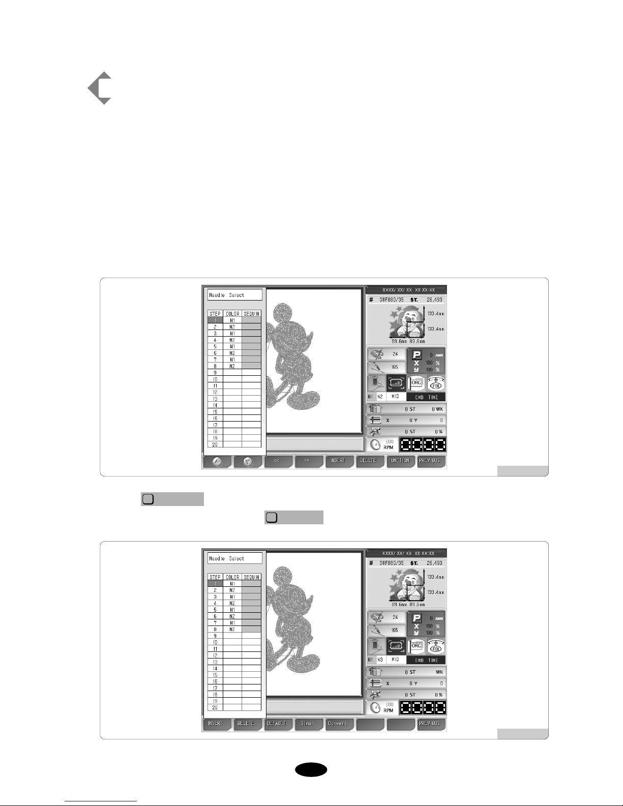
55--4477
[Exercise 5.4.4-3] Needle bar change
No. 1 needle has brown thread, and No. 2 needle has blue thread.
The order of color is 1-2-1-2-1-2-1-2-1-2. It is needed to change all
embroidery colors to brown by using the needle bar change
function.
First of all, call a design.
(For design call, see “5.2 Design Call”.)
Use the select buttons as in <Fig. 5.4.4-1> to set the order of colors as 1-2-1-2-1-2-1-2-1-2.
Make the setting as in <Fig. 5.4.4-12>.
When is pressed on the needle bar select screen as in <Fig. 5.4.4-12>, the screen
appears as in <Fig. 5.4.4-13>. Press .
CONVERT
F5
FUNCTION
F7
[Fig. 5.4.4-12]
[Fig. 5.4.4-13]

55--4488
The screen like <Fig. 5.4.4-11> appears. Move to No. 2 needle bar .
[Fig. 5.4.4-14]
Press 1 on the number key pad, and press .
In <Fig. 5.4.4-15>, confirm that the needle bar is changed at No. 2 position.
SELECT
F7
Press .
PREVIOUS
F8
[Fig. 5.4.4-15]
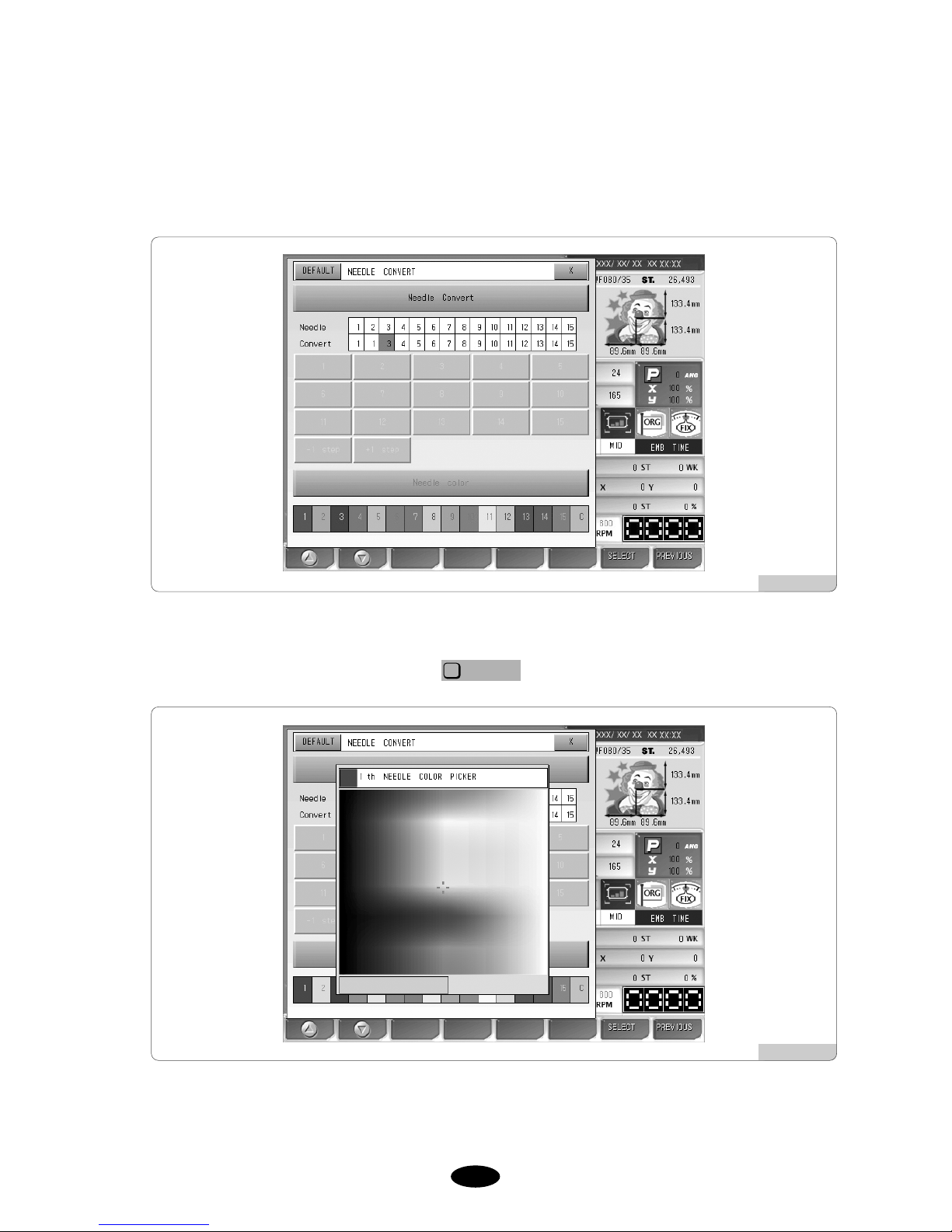
55--4499
(3) Needle color
This function is to easily show the needle bar (color) change-related information on the design by marking colors
on each needle bar. It does not affect the actual embroidery work.
<Fig. 5.4.4-16> appears when the needle bar color is pressed.
Use the number buttons to select the desired needle bar, and then <Fig. 5.4.4-17> appears where colors can be
chosen. Press the desired color for selecting it, and then the color confirmation section is changed with the color
chosen. If the color is what you wanted, press .
SELECT
F7
On the color change window in <Fig. 5.4.4-17>, use the frame speed key to adjust the cursor move speed.
[Fig. 5.4.4-16]
[Fig. 5.4.4-17]

55--5500
5.4.5 Frame offset setting
The function is to decide the starting position of the embroidery design, the offset position, and the stop position
after work completion to ensure more convenient embroidery work.
<Fig.5.4.5-1> appears when selecting “Frame Offset Setting” on the menu.
SETTING
F3
The sub-menus for frame coordinates are as below:
[Fig. 5.4.5-1]
(Design Start Point) : It decides the frame’s start position for the called design. When the
starting position is pre-determined, regardless of the current frame locations, the frame automatically moves to
the start position when the embroidery work begins.
(Offset Middle Point) : It decides the middle position between the design starting position and
the stop position when the design is completed to prevent the needle bar from contacting the embroidery
materials. If the function is unnecessary, the same value can be entered for the design starting position and the
stop position after design is completed. It does not adversely affect the machine operation.
(Design Offset Point) : It decides the frame position where design is completed or the offset
frame position. This function is useful for applique work and the replacement of hoop.
OFFSET
F3
MIDDLE
F2
START
F1
[ Caution ]
1. If the frame coordinates setting (offset) is not set as “Yes” in the basic setting, the setting of the frame
coordinates is not applied during embroidery.
2. If the frame origin is incorrect, it is difficult to find the frame coordinates.

55--5511
[Exercise 5.4.5-1] Design start position - X : 500, Y : 300
Offset middle position - X : 1000, Y : 1000
Stop position after design completion (offset) - X : 1500, Y : 1700
Make the above settings.
Press “Frame Offset Setting” on the setting menu.
Then <Fig. 5.4.5-1> appears.
Use , to move to “Design Start Point” and press .
It will enable the design start point.
Set the X, Y values for the frame location by using the frame move buttons.
Use
,
to move to the “Offset Middle Point” and select . Then the offset mid-
position will be enabled.
Set the X, Y values for the frame location by using the frame move buttons.
Press
,
to move to “Design Offset Point” and then press .
Then, the stop position becomes enabled after the embroidery work is completed.
Set the X, Y values for the frame location by using the frame move buttons.
Press .
SELECT
F7
F2
F1
SELECT
F7
F2
F1
SELECT
F7
F2
F1

55--5522
5.4.6 Options Setting
This function is to set the options for the embroidery machine. Among the options, there are cording, sequin and
boring. <Fig. 5.4.6-1> shows the screen for option setting.
No.3, No.5, No.6 and No.7 menus can be activated when No.2 and No. 4 menus are enabled.
There are 20 menus under Option Setting. Press to move to the next screen for checkout.
Press , to move around the menu.
Press to initialize the settings to default values.
Press to see the next menu.
Press to select the menu. Press to exit from setting.
PREVIOUS
F8
SELECT
F7
NEXT
F4
DEFAULT
F3
F2
F1
NEXT
F4
[Fig. 5.4.6-1]

55--5533
④ Use the number buttons and press “1(Yes)”. (<Fig. 5.4.6-3>)
T o correct the entered data, press . To cancel, press .
PREVIOUS
F8
(1) Cording setting
① Press from the main function menu.
② Select Options Setting and press .
③ Select “1. CORDING” and press . <Fig. 5.4.6-2> appears for setup.
SELECT
F7
SELECT
F7
SETTING
F3
[Fig. 5.4.6-2]
[Fig. 5.4.6-3]

55--5544
⑤ Press .
Cording setting has been completed.
⑥ Press “9. CORDING RPM.”
<Fig. 5.4.6-4> is the screen for speed setting.
⑦ Enter the desired speed using the number keypad within the speed range from the maximum to the minimum
speed.
⑧ Press .
Cording setting has been completed.
[Fig. 5.4.6-4]

55--5555
(2) Sequin setting (In case of single type sequin)
① Press on the main function menu.
② Select Options Setting on the setting screen and press .
③ Press either “2. Sequin L” or “4. Sequin R.” As in <Fig. 5.4.6-5>, the Sequin L has the setting screen like
<Fig. 5.4.6-5>, while Sequin R has the setting screen like <Fig. 5.4.6-6>.
SELECT
F7
SETTING
F3
[Fig. 5.4.6-5]
[Fig. 5.4.6-6]

55--5566
④ Press No.1 (SQ30) on the number keypad. To correct, press To cancel, press .
⑤ Press .
⑥ After setting the sequin type, set the sequin length.
Press “3. Sequin (L) Length” or “5. Sequin (R) Length”
Then, the screens <Fig. 5.4.6-7> and <Fig. 5.4.6-8> appear respectively for the sequin(L), (R) length.
PREVIOUS
F8
[Fig. 5.4.6-7]
※ Three types of sequin setting can be performed.
No(0) ------------------------------- Sequin disabled
SQ30(1) ----------------------------Single type enabled
SQ30D(2) ------------------------- Double type enabled
SQ40i(3) ---------------------------Individual sequin type enabled

55--5577
⑦ Enter a desired figure within the setting range of 3.0mm~9.9mm using the number keypad.
⑧ Press .
[Fig. 5.4.6-8]
[Fig. 5.4.6-9]
※ SQ40i Setting
IIf SQ40i is chosen as sequin type in ‘2) Sequin Setting’, first of all, the menu for setting the motion range
of the needle motor appears as in <Fig. 5.4.6-7> and <Fig.5.4.6-8>,and the menu comes up before the
menu for setting sequin (L)(R) length spears as in<Fig. 5.4.6-9> and <Fig. 5.4.6-10>.
Enter a figure within the setting range of 3mm to 15mm.
[Example] When using 3mm spangles, press ‘3’ using the number keypad to set it at 3mm.
When using 7mm spangles, press ‘7’ using the number keypad to set it at 7mm.

55--5588
[Fig. 5.4.6-10]
⑩ Enter a desired figure within the setting range of 300rpm~800rpm using the keypad.
⑪ Press .
The sequin setting has been completed.
[Fig. 5.4.6-11]
⑨ Press “6. Sequin RPM.” (T o set the right sequin speed, press No.7.)
<Fig. 5.4.6-11> is the speed for speed setting.

55--5599
④ Enter the number of the needle bar equipped with the boring within the range of permissible values.
T o correct the entered data, press . To cancel, press .
⑤ Press .
This completes the boring setting.
PREVIOUS
F8
(3) Boring setting
① Press on the main function menu.
② Select Options Setting on the setting screen and press .
③ Select “8. Boring Needle” and press .
<Fig. 5.4.6-12> appears for setup.
SELECT
F7
SELECT
F7
SETTING
F3
[Fig. 5.4.6-12]

55--6600
5.4.7 The Others Settings
Press Other Settings on the setting menu, and then <Fig. 5.4.7-1> will appear. There are six setting menus
including the cutting needle bar setting, the thread sensing function by head, the trimming-related setting, the sound
volume setting, the thread condition setting, and the date/time setting under the other settings menu.
[Fig. 5.4.7-1]

55--6611
(1) Cut Needle Set
This function is to set the needle bar equipped with the specially designed cutting needle to cut the embroidery
fabric in the desired shape. To use this function, during embroidery, thread detection and trimming functions
shall be suspended. The cutting needle bar setting is the function to automatically suspend the unnecessary
functions, when the cutting function is used. <Fig. 5.4.7-2> is the screen where the “Cut Needle Set” is pressed
in <Fig. 5.4.7-1>. Pink means that the concerned needle bars were chosen for embroidery, and bright yellow
means that the needle bars were set for cutting.
<Fig. 5.4.7-2> shows that No. 4 Head is set as the cutting needle bar.
[Fig. 5.4.7-2]

55--6622
[Exercise 5.4.7-1] Converting No. 2, 3, 4 Needle Bar to Cutting Function
Press on the main menu.
Select “The Others Setting” on the setting screen.
<Fig. 5.4.7-1> appears.
Select “1. Cut Needle Set.”
<Fig. 5.4.7-2> appears.
Use
,
to move to No. 2, 3, 4 needle bars, and press .
As in <Fig. 5.4.7-3>, if No. 2, 3, 4 heads are displayed in yellow, they have been converted into cutting
function successfully.
SELECT
F7
F2
F1
SETTING
F3
[Fig. 5.4.7-3]
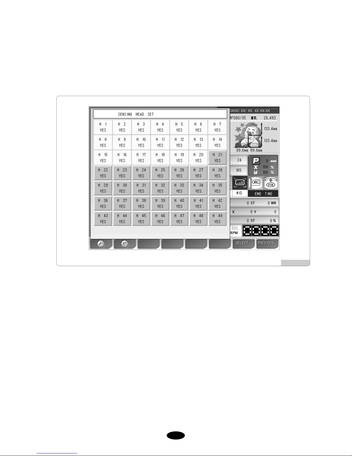
55--6633
(2) Sensing Head Set
This function is to turn on or off the thread sensor of each head. <Fig. 5.4.7-4> shows that the operating program
support up to 49 heads, and currently 20 heads have been selected for this function. The bright yellow mark
means that the thread sensor for the concerned head is in operation.
[Fig. 5.4.7-4]

55--6644
Exercise 5.4.7-2] Disabling the thread sensors of No. 2, 10, 13 heads
Press on the main screen.
Select “2. Sening Head Set” on the Other Settings.
Then <Fig. 5.4.7-4> appears.
Move to No. 2, 10, 13 heads and press .
As in <Fig. 5.4.7-5>, if No. 2, 10, 13 heads are marked in pink, it means that their thread sensors are disabled.
SELECT
F7
SETTING
F3
[Fig. 5.4.7-5]

55--6655
(3) Trim Set
There are three trimming-related settings: Trimming start angle setting, main-shaft start acceleration speed
setting, and bartack length setting for trimming.
① Trim Angle Setting
This function is to change the main shaft angle when the trimming motor feed begins.
– The default is 0。, and the value can be adjusted from -5。to 5。by the unit of 1。.
② Accelation
This function is to set the time taken for the machine to reach the embroidery speed after the machine started
operating at the inching speed.
– The default is Normal. Either Normal(0) or Slow(1) can be chosen.
embroidery speed
inching speed
Time
start
t
[Fig. 5.4.7-6]

55--6666
③ Start or End B / T Length
This function is to set the length of a stitch while bartack is performed. .
For thin or wool fabric, set the value at 0.8[mm], and the first stitch plaiting and trimming can be effectively
performed.
– The default is 0.8[mm], and the value can be adjusted from 0.6 to 0.8[mm] by the unit of 0.1[mm].
(4) Sound volume
The function is to set the volume of the sound issued when the power is turned on/off or when a menu is
selected.
– The default is OFF (0), and the value can be set at the range of 1 to 10.
(5) Head select
This function is to select the heads you desire to use.
It is not available in this type of machine.
(6) Thread Select
This function is to select appropriate threads by conditions.
– The default is Normal(0). For wool, select Wool(1).
(7) Time Setting
This function is to change the date and time displayed on the upper right side of the screen.
On the Other Settings menu, select No. 7, and the screen where date and time can be set appears as in <Fig.
5.4.7-4>.
Use the menu move buttons , , and , for setting.
For date and time setting, see “4.4.2 Date/Time Change”.
SAVE
F7
SELECT
F6
F2
F1

•Position : It shows whether the called design contacts the X, Y limits without actually carrying out
embroidery work.
•Gauge : It automatically generates gauges for the embroidery outline in accordance with the values set in
“14. Optimize Method”under “Embroidery parameter setting.”
•Exclude : It is used to embroider the outline of the called design.
•Fastview : It virtually shows the embroidery work for each stitch to display the progressing direction of
the design or the stage of color changes.
•Trace : It briefly checks whether the frame moves beyond the X, Y limits, if the embroidery work begins
from the current position of the frame.
5.5.0
Ready
- This function is to check whether the machine is prepared to conduct embroidery before
actual work. There are five functions including work position, gauge, Exclude, Fastview,
and Trace.
Press on the main menu and then sub-menus will appear as in <Fig. 5.5.0-1>.
READY
F4
[Fig. 5.5.0-1]

5.5.1 Position
This function is to set the desired position to begin embroidery.
① Select the work position in <Fig. 5.5.0-1>, and then <Fig. 5.5.1-1> will appear.
② The dotted lines within the frame in <Fig. 5.5.1-1> is the maximum horizontal and vertical sizes. The plus (+)
mark within the dotted lines indicates the starting point of embroidery and the position of the frame where the
current needle bar will begin embroidery.
③ When the desired position within the frame is pressed, the embroidery design will move to the desired position.
If there is a red part in the dotted lines, which indicate a design, errors will occur in the X, Y limits during
embroidery. Therefore, make sure to select a position where the entire dotted lines are positioned within the
frame.
③ If “Move”is selected after position setting, the frame will move to locate the embroidery design at the desired
position.
[Fig. 5.5.1-1]
[ Caution ]
When the main power is off, and the frame is pushed by hand, the frame’s origin will change. Likewise, when
the frame’s origin is changed, the work position function does not properly perform.
(For frame’s origin, see “5.8.4 Frame Origin.”)

5.5.2 Gauge
This function is to automatically create the gauge of the design outline.
① Use the menu move buttons in <Fig. 5.5.0-1>, select gauge, and press . And then <Fig. 5.5.2-1>
will appear.
SELECT
F7
② Press in <Fig. 5.5.2-1>, and as in <Fig. 5.5.2-2>, the menu for design saving will appear. Select the
room to save the design and press , and the design will be saved in the memory. To cancel the
saving, press .
PREVIOUS
F8
COPY
F7
SAVE
F1
② In <Fig. 5.5.2-1>, is the function to check whether the gauge line moves beyond the frame by
moving the frame along the gauge line.
FRAME
F2
[ Note ]
The distance between the called design and the gauge line can be set in “14. Optimize Method”of “5.4.2 EMB
Parameter Setting.”
[Fig. 5.5.2-1]
[Fig. 5.5.2-2]

5.5.3 Exclude
This function is to embroider the outline of the called design.
① Use the menu move buttons in <Fig. 5.5.0-1> to select Outline and press . And <Fig. 5.5.3-1>
will appear.
SELECT
F7
② Press in <Fig. 5.5.3-1>, and then the menu for design saving will appear as in <Fig. 5.5.3-2>. Select
the room for design saving and press . Then the design will be saved in the memory. To cancel the
saving, press .
PREVIOUS
F8
COPY
F7
SAVE
F1
② In <Fig. 5.5.3-1>, is the function aimed to check whether the frame moves beyond the outline by
moving the frame along the outline.
FRAME
F2
[Fig. 5.5.3-1]
[Fig. 5.5.3-2]

5.5.4 Fastview
This function is to show the virtual embroidery work for the chosen design. There are such sub-menus such as
color, 100 stitches, 1000 stitches, slow view, and fast view.
<Fig. 5.5.4-1> is the screen when “Route Check”is pressed in <Fig. 5.5.0-1>.
As in <Fig. 5.5.4-2>, the embroidery work for the chosen design is displayed one stitch at a time. This shows the
procedures of producing the entire design.
[Fig. 5.5.4-1]
[Fig. 5.5.4-2]
 Loading...