

Page 1
PRO-SERIES HD
Digital Video Recorder
INSTRUCTION MANUAL
Page 2

2
Important Information
FCC Verification
This equipment has been tested and found to comply with the limits for
Class B digital device, pursuant to part 15 of the FCC Rules. These limits
are designed to provide reasonable protection against harmful interference in a residential installation. This equipment generates, uses and
can radiate radio frequency energy and, if not installed and used in accordance with the instructions, may cause harmful interference to radio
or television reception, which can be determined by turning the equipment off and on, the user is encouraged to try to correct the interference
by one or more of the following measures:
• Reorient or relocate the receiving antenna
• Increase the separation between the equipment and the receiver
• Connect the equipment into an outlet on a circuit different from that
to which the receiver is connected
• Consult the dealer or an experienced radio/TV technician for help
These devices comply with part 15 of the FCC Rules. Operation is subject to the following two conditions:
• These devices may not cause harmful interference
• These devices must accept any interference received, including interference that may cause undesired operation
Important Notice - All jurisdictions have specific laws and regulations
relating to the use of cameras. Before using any camera for any purpose, it is the buyer’s responsibility to be aware of all applicable laws
and regulations that prohibit or limit the use of cameras and to comply
with the applicable laws and regulations.
FCC Regulation (for USA): Prohibition against eavesdropping
Except for the operations of law enforcement officers conducted under
lawful authority, no person shall use, either directly or indirectly, a device operated pursuant to the provisions of this Part for the purpose
of overhearing or recording the private conversations of others unless
such use is authorized by all of the parties engaging in the conversation.
Warning - Changes or modifications made to this device not approved
expressly by the party responsible for compliance could void the user’s
authority to operate the equipment.
Important Safety Instructions
• Make sure product is fixed correctly and stable if fastened in place
• Do not operate if wires and terminals are exposed
• Do not cover vents on the back of the device and allow adequate
space for ventilation
• Only use the power adapter supplied with the DVR
Password Information
To ensure your privacy, this device supports password protection. The
default all-access username is admin, the default password is 12345.
To ensure your on-going privacy, we strongly recommend setting a password as soon as possible. Choose something that you’ll remember, but
that others would be unlikely to guess.
Important Notice - Do not lose or forget your password. To ensure that
your DVR has the best security possible, password recovery has been
designed to be a complicated and time consuming process. Only a select
number of staff at Swann Technical Support Telephone Helpdesk can
assist. Password retrieval can take several days, which means you will
not be able to access your DVR during this time.
Page 3

3
Contents
Important Information 2
Contents 3
Chapter 1 - Menu 5
Menu Layout 6
Chapter 2 - Camera Configuration 7
Record: Parameters - Record 8
Record: Parameters - Substream 9
Camera: OSD 10
Camera: Image 11
Camera: Motion 12
Motion Detection Tips 13
Camera: Privacy Mask 14
Camera: Video Tampering 15
Camera: Video Loss 16
Camera: Video Quality Diagnostics 17
Camera: PTZ 18
Camera: PTZ - Creating a Preset 19
Camera: PTZ - Creating a Patrol 20
Camera: PTZ - Creating a Pattern 21
Camera: PTZ - Linear Scan 22
Chapter 3 - Recording Configuration 23
Record: Schedule 24
Record: Advanced 25
Record: Holiday 26
Manual: Record 27
Chapter 4 - Playback 28
Playback: Normal 29
Playback: Event 30
Playback: Tag 31
Playback: Smart 32
Chapter 5 - Export 34
Export: Normal 35
Export: Event 36
Chapter 6 - Configuration 37
Configuration: General - General 38
Configuration: General - DST Settings 39
Configuration: General - More Settings 40
Configuration: Network - Extranet Access 41
Configuration: Network - General 42
Configuration: Network - PPPOE 43
Configuration: Network - NTP 44
Configuration: Network - Email 45
Page 4

4
Contents
Configuration: Network - SNMP 46
Configuration: Network - NAT 47
Configuration: Network - More Settings 48
Configuration: Live View - General 49
Configuration: Live View - View 50
Configuration: Exceptions 51
Configuration: User 52
Chapter 7 - System Maintenance 53
System Maintenance: System Info 54
System Maintenance: Log Information 55
System Maintenance: Import/Export 56
System Maintenance: Upgrade 57
System Maintenance: Default 58
System Maintenance: Net Detect 59
System Maintenance: HDD Detect 60
HDD: General 61
HDD: Advanced 62
Manual: Video Quality Diagnostics 63
Warranty Information 64
Helpdesk & Technical Support 65
Page 5

5
Menu
The Menu is where you control
the various actions and options
that are available on the DVR.
You can also access previously recorded video for playback
and to export to a USB storage
device such as a flash drive.
To maintain system integrity, a
firmware upgrade can be performed when available and access to the Shutdown menu to
restart or safely turn off the
DVR.
5
26-05-2015 9:30:15 Tue
Camera 02
26-05-2015 9:30:15 Tue
26-05-2015 9:30:15 Tue
26-05-2015 9:30:15 Tue
Camera 01
Camera 03 Camera 04
Page 6

6
Menu Layout
Playback: Click this to access all Normal and Motion event recordings.
There are several playback modes to choose from, such as Normal,
Event, Tag and Smart. You can also play video files that have been exported to a USB storage device such as a flash drive.
Export: Click this to copy or backup footage from the DVR. You’ll need a
compatible USB storage device such as a flash drive to export the data.
Manual: Access manual controls for the recording functions of the DVR.
HDD: Where you’ll be able to access information about and adjust the
settings of your hard drive.
Record: Access recording options, such as quality, resolution, bitrate
and the recording schedule.
Camera: Adjust image settings such as brightness and contrast and
access to Video Quality Diagnostics to alert you to blurred images and
abnormal brightness. Controls for Motion, Privacy Mask and Video Tampering are also available here.
Configuration: Access and configure many settings of the DVR, includ-
ing your network settings, adjusting the time & date and creating or
altering user accounts.
Maintenance: For accessing system information, log information and to
upgrade the firmware.
Shutdown: To shutdown, reboot or log out of the DVR.
To shutdown or reboot the DVR, or
simply log out of the current user account, click the “Shutdown” button.
To ensure the integrity of your data
and recordings, always select “Shutdown” when powering off the DVR.
To access the Menu,
right-click the mouse
then select “Menu”.
Hover the mouse cursor over each button to
display a description.
To exit the Menu click
“Exit” or right-click the
mouse.
Page 7

7
Camera Configuration
The camera configuration options are available in the “Record” and “Camera” menus
that are accessible from the
Menu. You can change the resolution and bitrate as well as image settings for brightness and
contrast. The DVR has several
controls for Motion, Video Tampering, Video Loss and Video
Quality Diagnostics as well as
the ability to apply one or more
masks for privacy.
7
Camera 01
26-05-2015 9:30:15 Tue
26-05-2015 9:30:15 Tue
Camera 02
Page 8
8
Record: Parameters - Record
Camera: Select a camera that you would like to edit.
Stream Type: By default “Video” is selected. Select “Video & Audio” if
you have an audio source connected to the DVR’s audio input.
Resolution: The default resolution is 1920 x 1080.
Frame Rate: The number of frames per second (fps) that the DVR will
record. The default is 12fps but can be changed to Full Frame when selecting a lower resolution.
Video Quality: The amount of data the DVR will use to record video. Low-
ering the quality reduces the file size of each video saved.
Pre-record: By default the DVR will record 5 seconds before an event
occurs. This reduces the chance of an event not being recorded. We recommend changing this to 10 seconds (10s).
Post-record: Same as above but the DVR will continue recording after
an event has occurred. 30 seconds (30s) is the recommended length.
Expired Time (day): Determines how long the video footage will remain
on the hard drive without it being overwritten.
Record Audio: Click the checkbox to enable when selecting “Video &
Audio” for the stream type.
• Click the “Restore” button to revert back to default settings.
• Use the “Copy” function to apply all settings to the other cameras.
• Don’t forget to click “Apply” to save settings.
• Click the “Back” button to go back to the Menu.
The Parameters function allows you to
change the resolution
and bitrate for each
camera connected. By
default the resolution
is 1920 x 1080 which
fits in with the capabilities of the provided
cameras.
Page 9

9
Record: Parameters - Substream
Camera: Select a camera that you would like to edit.
Stream Type: By default “Video” is selected. Select “Video & Audio” if
you have an audio source connected to the DVR’s audio input.
Resolution: The default streaming resolution is 352 x 240. You can se-
lect a higher resolution to increase the streaming quality (up to 960 x
480) or you can select a lower resolution (176 x 120 or 320 x 240) if you’re
having issues streaming live video from your DVR to your mobile device
or computer via SwannView Plus.
Frame Rate: The default frame rate for streaming is 30fps for NTSC and
25fps for PAL. You can change this to 12fps or 6fps to reduce the amount
of data required.
Video Quality: The amount of data the DVR will use to stream live video.
Lowering the quality reduces the amount of data required.
• Click the “Restore” button to revert back to default settings.
• Use the “Copy” function to apply all settings to the other cameras.
• Don’t forget to click “Apply” to save settings.
• Click the “Back” button to go back to the Menu.
The Substream menu
gives you control on
how video is streamed
to your mobile device
or computer using the
SwannView Plus app
and Windows software.
You can change the
resolution and bitrate
if you’re having issues
streaming live video
from your DVR.
Page 10
10
Camera: OSD
Camera: Select a camera that you would like to edit.
Camera Name: Select a name for the camera you’ve selected. It can be
up to 32 characters in length.
Display Name: This is enabled by default. Click the checkbox if you don’t
want the camera name displayed.
Display Date: This is enabled by default. Click the checkbox if you don’t
want the date displayed.
Display Week: This is enabled by default. Click the checkbox if you don’t
want the day displayed.
Date Format: Select how you would like the date to be displayed.
Time Format: Choose between “12-hour” and “24-hour” time.
Display Mode: Select how you would like the on-screen display to ap-
pear on-screen. It’s worth having a look at the different settings available to see what best fits.
OSD Font: Select a different font size for the on-screen display.
Use the mouse to click and drag the display name and date to the desired position.
• Click the “Restore” button to revert back to default settings.
• Use the “Copy” function to apply all settings to the other cameras.
• Don’t forget to click “Apply” to save settings.
• Click the “Back” button to go back to the Menu.
Camera 01
26-05-2015 9:30:15 Tue
Page 11
11
Camera: Image
Camera: Select a camera that you would like to edit.
Time Segment 1 & 2: This function gives you the ability to assign a par-
ticular pre-set mode or customised settings for two time segments. For
example, one time segment for day time and the second time segment
for night time.
Mode: You can select from a number of different pre-set modes.
Brightness: This changes how light the image appears to be.
Contrast: This increases the difference between the blackest black and
the whitest white in the image. Don’t set the contrast too high as it will
degrade the image quality.
Saturation: This alters how much colour is displayed in the image. The
higher the saturation, the more bright and vivid colours will appear.
Hue: This changes the colour mix of the image.
Sharpness: Increase or decrease the overall sharpness of the image.
Increasing the sharpness will also increase the level of video noise that
is visible.
Denoising: This will reduce the overall noise content in the image.
Please note, any changes made to image settings will affect your
recordings.
• Click the “Restore” button to revert back to default settings.
• Use the “Copy” function to apply all settings to the other cameras.
• Don’t forget to click “Apply” to save settings.
• Click the “Back” button to go back to the Menu.
You can adjust the
various image settings available to help
fine-tune the Motion
sensitivity. At night,
images that you see
from the camera may
seem to flicker or
have increased noise.
By tweaking the image settings, you can
eliminate noise and increase image quality.
Camera 01
26-05-2015 9:30:15 Tue
Page 12
12
Camera: Motion
Camera: Select a camera that you would like to edit.
Enable Motion Detection: Click the checkbox to enable.
Settings: Here you can define what will happen when the camera you’ve
selected has detected movement -
Trigger Channel: Select additional cameras to start recording.
Arming Schedule: Adjust your arming schedule by selecting a start day
and a time period (24-hour time). Use the “Copy” function to apply all
settings to the other cameras. Don’t forget to click “Apply” to save settings. Click “OK” to exit.
Linkage Action: Options available are full screen monitoring, enabling
the DVR’s internal buzzer, send alerts to the SwannView Plus Windows
software (software must be running to receive alerts) and to send an
email. Don’t forget to click “Apply” to save settings. Click “OK” to exit.
Sensitivity: This setting is controlled by a slider, allowing you to set a
value between L (low) and H (high). The closer to H the slider is set, the
more sensitive the detection will be.
The entire view of the camera is enabled, however you can select certain
areas if you wish. Using the mouse, click the “Clear” button then click
and drag to select the area that you want to enable. To enable the entire
view of the camera, click the “Full Screen” button.
• Use the “Copy” function to apply all settings to the other cameras.
• Don’t forget to click “Apply” to save settings.
• Click the “Back” button to go back to the Menu.
Whether you’re waiting
for an expected event,
hoping you don’t spot
an unwelcome visitor,
or just curious about
what happens when
you’re not around, Motion can be configured
to record video and to
alert you when movement is detected.
Camera 01
26-05-2015 9:30:15 Tue
Page 13
13
Motion Detection Tips
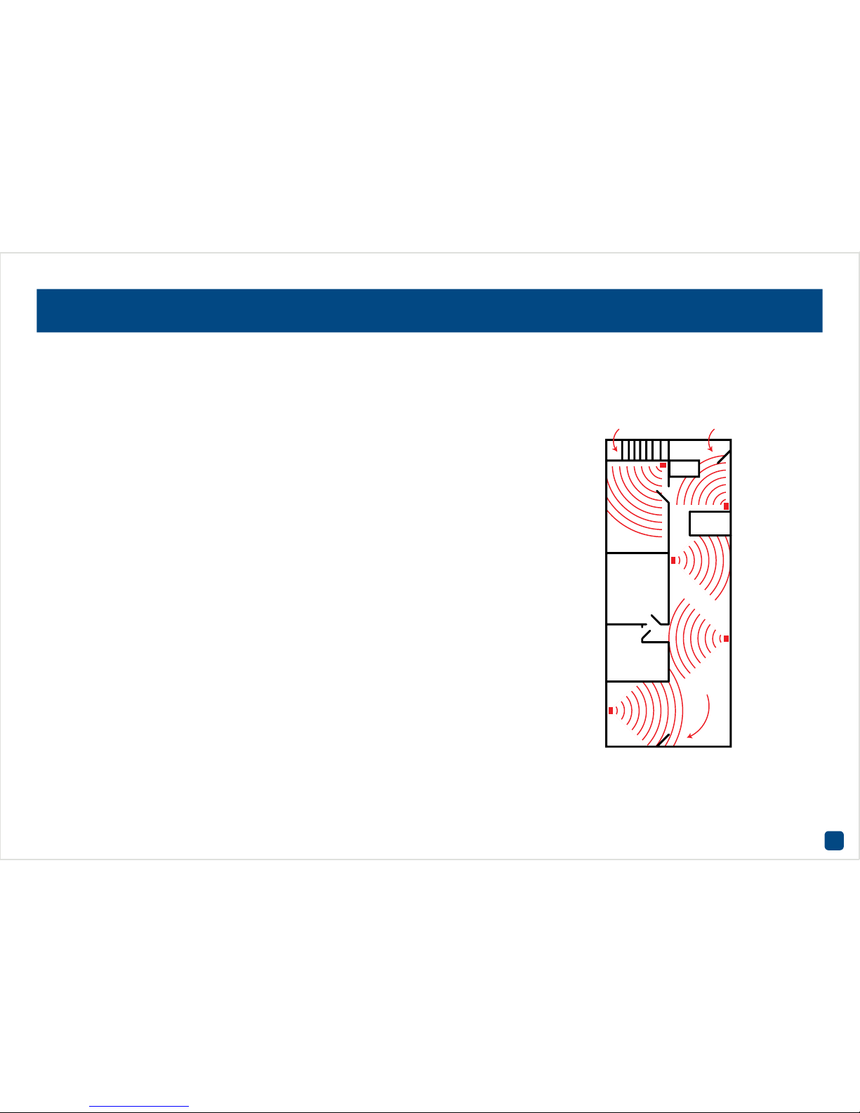
Placement of the cameras
1. Keep cameras 10 to 15 feet (3 to 4 metres) away from heating vents, where the sunlight shines in, and
radiators. If a camera detects a swift change in motion, even that of a cloud passing quickly over direct
sunlight shining into your living room, motion detection could be activated.
2. Place cameras in areas where people have to walk through, like the stairwell, main hallway or entry
door. That way, an intruder will activate motion detection regardless of where they are headed. Intruders
usually go right for the master bedroom, so put a camera near that room or other rooms where you have
valuables, like the study.
3. Walk through your house and assess where intruders are most likely to enter, and what path they would
take. Most burglars enter the home through a front or back door, so it’s advisable to place the cameras
near those areas.
4. When installing cameras outside, it’s important to keep your front and backyard well-lit for ideal night
vision and motion detection. It’s common for intruders to enter a home through an unlocked garage or by
using a garage door opener in an unlocked car located in the driveway.
Avoiding False Triggers
1. A flag or foliage that is blown by the wind - angle the camera so wind-blown objects are out of the
camera’s view.
2. Pets moving in front of the camera - lower the sensitivity level and/or point the camera into areas that
are not particular high-traffic for your pets.
3. Vehicles moving in the background - angle the camera so as to avoid movement in the background.
4. Moving air from a heater or air conditioner - angle the camera away from these sources.
5. Movement reflected off smooth surfaces - lower the sensitivity level and/or avoid pointing the camera
directly at glass surfaces.
Motion Detection is an essential part of your security system and is the main method used to detect when someone is in your home. When motion
has been detected, a signal is sent to your DVR that alerts you to a potential threat in your home. It does this in several ways such as activating its
internal buzzer, sending an email and sending an alert to your mobile device or computer. You can also trigger the other cameras to start recording.
Bedroom Backdoor
Hallways
Frontdoor
Page 14

14
Camera: Privacy Mask
Camera: Select a camera that you would like to edit.
Enable Privacy Mask: Click the checkbox to enable.
Using the mouse, click and drag to select the area that you want to enable for a mask (as shown above). Up to four masks can be created (each
mask is colour coded) per camera.
Click the “Clear All” button to clear all masks or click on a particular
mask to clear.
• Use the “Copy” function to apply all settings to the other cameras.
• Don’t forget to click “Apply” to save settings.
• Click the “Back” button to go back to the Menu.
The Privacy Mask
function can be used
if you want to obscure
part of your image.
You can also use this
to minimize false triggers when movement
is detected. Up to four
masks can be created per camera. Areas
obscured by a mask
won’t be shown live or
recorded.
Camera 01
26-05-2015 9:30:15 Tue
Page 15

15
Camera: Video Tampering
Camera: Select a camera that you would like to edit.
Enable Video Tampering Detection: Click the checkbox to enable.
Settings: Here you can define what will happen when the camera you’ve
selected is being tampered with -
Arming Schedule: Adjust your arming schedule by selecting a start day
and a time period (24-hour time). Use the “Copy” function to apply all
settings to the other cameras. Don’t forget to click “Apply” to save settings. Click “OK” to exit.
Linkage Action: Options available are full screen monitoring, enabling
the DVR’s internal buzzer, send alerts to the SwannView Plus Windows
software (software must be running to receive alerts) and to send an
email. Don’t forget to click “Apply” to save settings. Click “OK” to exit.
Sensitivity: The sensitivity setting is controlled by a slider, allowing you
to set a value between L (low) and H (high). The closer to H the slider is
set, the more sensitive it will be.
• Use the “Copy” function to apply all settings to the other cameras.
• Don’t forget to click “Apply” to save settings.
• Click the “Back” button to go back to the Menu.
Any security system
can be vulnerable to
attack or image failure. Tamper Proofing
can be used in scenarios where someone
may cover up the camera’s field of view or if
they are attempting to
tamper with the video
signal.
Camera 01
26-05-2015 9:30:15 Tue
Page 16
16
Camera: Video Loss
Camera: Select a camera that you would like to edit.
Enable Video Loss Alarm: Click the checkbox to enable.
Settings: Here you can define what will happen when the camera you’ve
selected has no incoming video signal -
Arming Schedule: Adjust your arming schedule by selecting a start day
and a time period (24-hour time). Use the “Copy” function to apply all
settings to the other cameras. Don’t forget to click “Apply” to save settings. Click “OK” to exit.
Linkage Action: Options available are full screen monitoring, enabling
the DVR’s internal buzzer, send alerts to the SwannView Plus Windows
software (software must be running to receive alerts) and to send an
email. Don’t forget to click “Apply” to save settings. Click “OK” to exit.
• Use the “Copy” function to apply all settings to the other cameras.
• Don’t forget to click “Apply” to save settings.
• Click the “Back” button to go back to the Menu.
Video Loss is regarded
as a potential alarm
event and is considered
to occur any time the
DVR doesn’t receive an
active video signal on
any of its inputs. When
an input has no incoming video signal, a “NO
VIDEO” message will
appear on-screen.
Camera 01
26-05-2015 9:30:15 Tue
Page 17
17
Camera: Video Quality Diagnostics
Camera: Select a camera that you would like to edit.
Enable Video Quality Diagnostics: Click the checkbox to enable.
Handling: Click this to instruct the DVR on how to alert you when there
is an error or notification and to set an arming schedule -
Arming Schedule: Adjust your arming schedule by selecting a start day
and a time period (24-hour time). Use the “Copy” function to apply all
settings to the other cameras. Don’t forget to click “Apply” to save settings. Click “OK” to exit.
Linkage Action: Options available are full screen monitoring, enabling
the DVR’s internal buzzer, send alerts to the SwannView Plus Windows
software (software must be running to receive alerts) and to send an
email. Don’t forget to click “Apply” to save settings. Click “OK” to exit.
Blurred Image: The DVR will alert you if the overall image is blurred.
This can happen if an object is too close to the camera or if someone is
intentionally obscuring the image.
Abnormal Brightness: The DVR will alert you if the camera detects a
bright source of light such as a torch or headlights.
Color Cast: The DVR will alert you if the camera detects an unwanted
tint in the image which is caused by a change to the lighting, white balance and if one or more color channels is strong or weak.
• Click the “Restore” button to revert back to default settings.
• Use the “Copy” function to apply all settings to the other cameras.
• Don’t forget to click “Apply” to save settings.
• Click the “Back” button to go back to the Menu.
Video Quality Diagnostics enables the
DVR to alert you if the
camera has a blurred
image, if there is abnormal brightness in
the image or if there is
an unwanted tint in the
image due to the lighting and white balance
of the camera (known
as Color Cast).
26-05-2015 9:30:15 Tue
Camera 02
Page 18
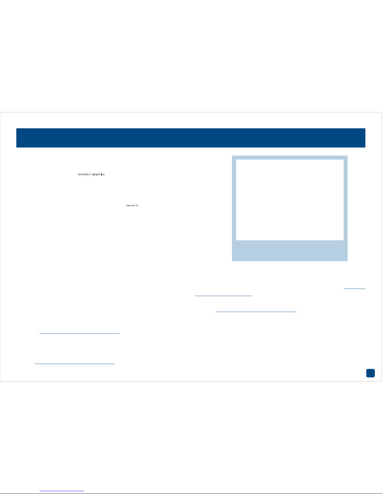
18
If you have a compatible PTZ camera connected to the DVR, use the PTZ
controls to move the camera as well as the ability to zoom into an object
and to control the level of focus (if available). You can create multiple
Preset positions, which can be recalled to focus the camera’s view to
a different position within the image. A Pattern can also be created to
record the camera’s movement along a predefined path.
Preset: A Preset is a particular position within the image that you would
like the camera to focus on. Up to 255 different Preset positions can be
created - see page 19 for more information.
Patrol: Patrol mode instructs the DVR to automatically move the cam-
era according to the Preset positions that have been created. You can
increase or decrease the duration before moving to the next Preset position - see page 20 for more information.
Pattern: A Pattern is created by recording the camera’s movements
along a predefined path. This gives you the flexibility to focus the camera’s view on multiple paths within the image automatically - see page
21 for more information.
Linear Scan: A Linear Scan instructs the camera to move in a horizontal
motion - see page 22 for more information.
PTZ Settings: Click this to configure the settings for your PTZ camera.
The DVR supports a number of different PTZ protocols. Consult the user
manual included with your camera then match those settings here.
Please note, the PTZ functions are dependent on the capabilities of your
camera and the protocol that it supports. Not all the functions available
will be compatible.
Camera: PTZ
Consult the user manual included with your
camera then match those settings here.
Camera 01
26-05-2015 9:30:15 Tue
Page 19
19
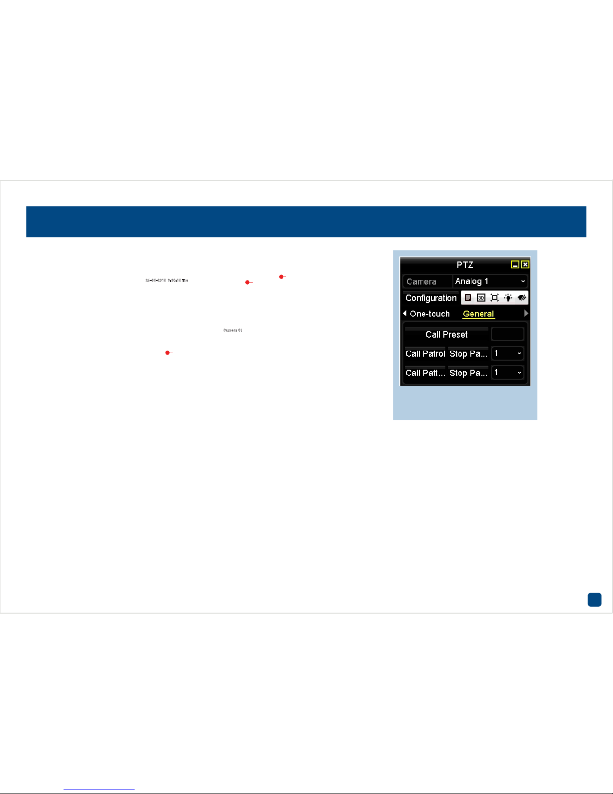
1. Use the PTZ controls to move the camera to the desired focal position.
The Zoom and Focus controls can also be used. You can use the Speed
control to determine how fast or slow the camera will move.
2. Each Preset position must be assigned a different number. Click the
Preset dialogue box as illustrated, input a number then click “Enter”.
You may want to make note which Preset position is assigned to each
number.
3. Click the “Set” button to save. Repeat these steps to create multiple
Preset positions.
Clear: Click this button to delete a Preset position.
Clear All: Click this button to delete all Preset positions.
PTZ: Click this button to access the full PTZ controls available. To ac-
cess the Preset positions, click the triangle button until you reach the
“General” menu (see above). Input a Preset number (click the dialogue
box) then click “Call Preset”. The camera will move to the Preset position assigned to that the number.
Click the “X” button to close the PTZ controls when finished.
• Click the “Back” button to go back to the Menu.
Camera: PTZ - Creating a Preset
Click the triangle button until you
reach the “General” menu.
Camera 01
26-05-2015 9:30:15 Tue
1
2
3
Page 20
20
When creating multiple Patrol groups (group 1 is the default), click the
Patrol dialogue box and change accordingly. Up to 4 different Patrol
groups can be created.
1. Click the “Set” button to create a Patrol.
2. Select a Preset position that you would like to add to the Patrol. The
Preset position will determine the order at which the camera will cycle
through the Patrol.
3. The Duration refers to the time span (in seconds) the camera will stay
at the corresponding Preset position. Change accordingly.
4. This defines the speed at which the camera will move from one Pre-
set position to the next.
Add: Click this button to add your Preset position to the Patrol. The Key-
Point will increase each time you add a Preset position.
OK: Click this button to finish.
Cancel: Click this button to cancel.
Clear: Click this button to delete the selected Patrol group.
Clear All: Click this button to delete all Patrol groups.
PTZ: Click this button to access the full PTZ controls available. Click
the triangle button until you reach the “General” menu. Select a Patrol
group then click “Call Patrol” to start. The camera will move to the first
Preset position and then move to the subsequent positions. Click “Stop
Patrol” to stop.
Click the “X” button to close the PTZ controls when finished.
• Click the “Back” button to go back to the Menu.
Camera: PTZ - Creating a Patrol
Patrol mode automatically
moves the camera using the
Preset positions created.
2
3
4
Camera 01
26-05-2015 9:30:15 Tue
1
Page 21

21
1. Use the PTZ controls to move the camera to the desired start position.
The Zoom and Focus controls can also be used. You can use the Speed
control to determine how fast or slow the camera will move.
2. Click the “Start” button to create a Pattern (only 1 pattern is support-
ed). As you move the camera to the desired areas within the image, the
DVR will record the exact movements that you make.
Stop: Click this button when you have finished creating a Pattern.
Clear All: Click this button to delete a Pattern.
PTZ: Click this button to access the full PTZ controls available. To ac-
cess the Pattern function, click the triangle button until you reach the
“General” menu (see above). Click “Call Pattern” to start. The camera
will move to the start position and then move along its predefined path.
Click “Stop Pattern” to stop.
Click the “X” button to close the PTZ controls when finished.
• Click the “Back” button to go back to the Menu.
Camera: PTZ - Creating a Pattern
Camera 01
26-05-2015 9:30:15 Tue
1
2
Click the triangle button until you
reach the “General” menu.
Page 22

22
1. Use the Left PTZ control to move the camera to the desired location
where you want to set the limit then click “Left Limit”.
2. Use the Right PTZ control to move the camera to the desired location
where you want to set the limit then click “Right Limit”.
PTZ: Click this button to access the full PTZ controls available. To ac-
cess the Linear Scan function, click the triangle button until you reach
the “One-touch” menu (see above). Click “Linear Scan” to start. The
camera will move horizontally from left to right according to the limits
that have been set.
Click the “X” button to close the PTZ controls when finished.
Click “Stop” to stop the Linear Scan.
• Click the “Back” button to go back to the Menu.
Camera: PTZ - Linear Scan
Click the triangle button until you
reach the “One-touch” menu.
Camera 01
26-05-2015 9:30:15 Tue
1 2
Page 23

23
Recording Configuration
The recording configuration options are available in the “Record” menu that is accessible
from the Menu. From here you
can access and change the recording schedule (default is
24/7 Motion Detection recording) for each camera connected
as well as enabling a schedule
when holidays are taken.
23
Page 24

24
Record: Schedule
Camera: Select a camera that you would like to edit.
Enable Schedule: This is enabled by default.
Edit: Click this to edit the schedule. You can set a schedule for one or
more days and different starting and ending times. You also have the
choice of selecting from one or more event types.
Continuous: The DVR will constantly record for any given period.
Motion: This is the default recording schedule. The DVR will only record
when it detects something moving in front of one or more cameras.
None: As the name suggests, the DVR will not record anything.
The Alarm, M | A and M & A event types are not available on this DVR.
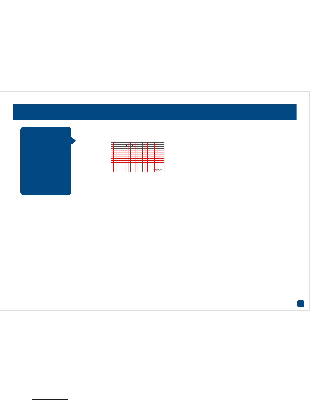
To edit the recording schedule, select the event type then move the pen
tool over the schedule. Click and hold the mouse then drag the pen tool
over the time segments that you want to change. You can also edit each
time segment individually.
In the above example, a Continuous recording schedule has been created for 012:00 a.m. to 08:00 a.m. then 06:00 p.m. to 012:00 a.m. and a Motion recording schedule for 08:00 a.m. to 06:00 p.m. Monday to Sunday.
• Use the “Copy” function to apply all settings to the other cameras.
• Don’t forget to click “Apply” to save settings.
• Click the “Back” button to go back to the Menu.
By default, a Motion
schedule has been
enabled for each connected camera. You
can however change
the schedule according to what fits in
with your needs. The
schedule is presented
as a 24-hour 7 days a
week grid and is colour
coded to represent the
event type.
Page 25

25
Record: Advanced
With the Overwrite function enabled, the DVR will record over previously
saved files stored on the hard drive. The DVR will always record over the
oldest files on your hard drive first.
It’s advisable to leave this function enabled as the DVR will always be
able to record events as they happen. However it does mean that you’ll
need to get important events backed up before they are overwritten.
• Don’t forget to click “Apply” to save settings.
• Click the “Back” button to go back to the Menu.
Page 26

26
Record: Holiday
Holiday schedules (up to 32) can be created by date, week or by the
month. When creating multiple schedules, the holiday with the highest
priority must be created first.
1. Edit: Click this to begin.
2. Holiday Name: Choose a title for the holiday period in question.
3. Enable: Click the checkbox to enable.
4. Mode: Select by date, week or month.
5. Start Date: Select a start date.
6. End Date: Select an end date.
• Don’t forget to click “Apply” to save settings.
• Click “OK” to exit.
• Click the “Back” button to go back to the Menu.
There are times when
you don’t want the DVR
to record using its default recording schedule. Perhaps you require it to record more,
or less, or just at different times. The Holiday function allows
you to define periods
of time where the DVR
will employ an alternative recording mode.
Page 27

27
Manual: Record
The green “ON” button indicates that each camera has a recording
schedule enabled. The red “OFF” button indicates that each camera has
no recording schedule enabled and the yellow “ON” button indicates
that each camera is recording manually. Click the button next to each
camera to change the recording status.
Continuous: The DVR will constantly record for any given period.
Motion Detection: This is the default recording schedule. The DVR will
only record when it detects something moving in front of one or more
cameras.
• Click the “Back” button to go back to the Menu.
This particular function allows you to
override any default
recording schedule
in place. The recording schedule for each
camera connected can
be changed.
Page 28

28
Playback
The Playback function gives you
the ability to search and play
previously recorded videos that
are stored on the DVR’s hard
drive. You have the choice of
selecting either Normal, Event,
Tag or Smart Playback. When
playing videos, you can add
Tags to help you identify people
or objects and you can then do
a search on those Tags.
28
Camera 01
23-11-2015 10:25:17 Mon
Camera 02
23-11-2015 08:24:47 Mon
Page 29

29
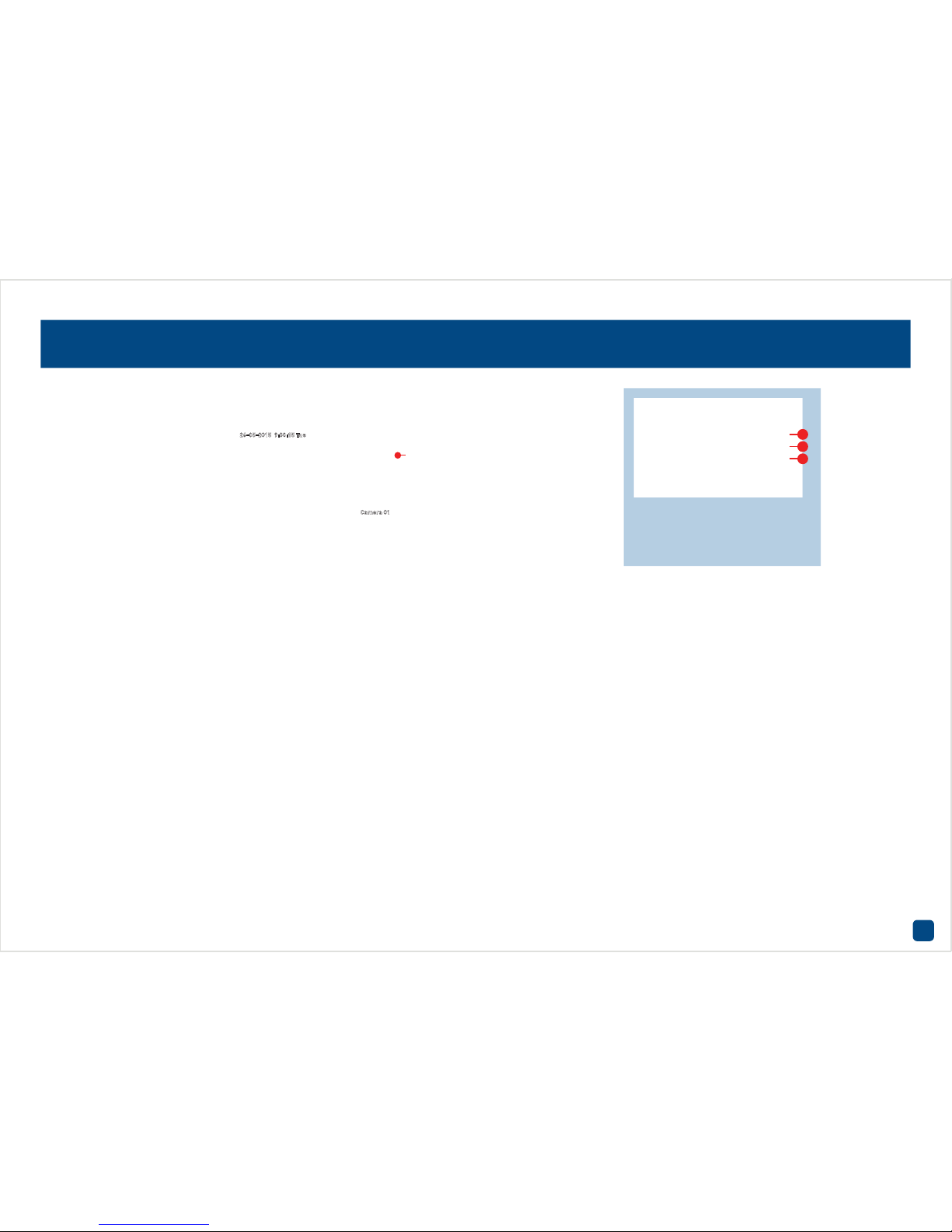
Playback: Normal
1. Mute: Mutes audio playback.
2. Start clipping: This button allows you to set mark in and out points on
your video which you can then export to a USB storage device such as a
flash drive. When you have selected a video to play, press this button at
the mark in point and press it again at the mark out point.
3. Save clip(s): Click this to save your clip(s) to a USB storage device. Al-
ternatively right-click the mouse to exit then click “Yes” to save. Select
the save location then click “Export”. Click “OK” to confirm.
4. Add default tag: Tagging allows you to record information such as
location or people within the video. Multiple tags can be added.
5. Add customized tag: As above but you can choose your own tag name.
6. Tag management: This allows you to edit or delete tags that you have
added to the video.
7. Zoom In: Click this to enter digital zoom mode. Click the video then
use the PIP (picture-on-picture) screen on the bottom right to select a
different area to zoom in to. Right-click to exit.
8. Play controls: These are your play, pause, rewind, forward, previous
day and next day controls.
9. Zoom In/Out: Zoom in and out of the timeline for precise control.
Select from one or more
camera(s) that you
would like to display for
playback.
The coloured dates
indicate video that is
recorded on those
particular days. Click the
“Play” button or doubleclick a date to play.
Normal Playback gives
you the ability to play
video from one or more
camera(s) on a given
day. The blue segments
located on the timeline
(underneath the video)
indicate a Normal
recording and the red
segments indicate an
Event recording.
Camera 01
23-11-2015 10:25:17 Mon
1 2 3 4 5 6 7 8 9
Page 30

30
Playback: Event
1. Mute: Mutes audio playback.
2. Start clipping: This button allows you to set mark in and out points on
your video which you can then export to a USB storage device such as a
flash drive. When you have selected a video to play, press this button at
the mark in point and press it again at the mark out point.
3. Save clip(s): Click this to save your clip(s) to a USB storage device. Al-
ternatively right-click the mouse to exit then click “Yes” to save. Select
the save location then click “Export”. Click “OK” to confirm.
4. Add default tag: Tagging allows you to record information such as
location or people within the video. Multiple tags can be added.
5. Add customized tag: As above but you can choose your own tag name.
6. Tag management: This allows you to edit or delete tags that you have
added to the video.
7. Zoom In: Click this to enter digital zoom mode. Click the video then
use the PIP (picture-on-picture) screen on the bottom right to select a
different area to zoom in to. Right-click to exit.
8. Play controls: These are your play, pause, rewind, forward, previous
day and next day controls.
9. Zoom In/Out: Zoom in and out of the timeline for precise control.
Select from one or more
camera(s) that you would
like to search on. Select
a start time & date and
end time & date then click
the “Search” button. The
DVR will start searching
and will then display
videos fitting your search
criteria. Double-click a
file to play.
You can change the
Pre-play and Post-play
times according to your
needs. Click “Back” to
commence a new search.
Event Playback gives
you the ability to search
for video footage that
has one or more events
over a set period of
time. For example, from
October to November
with a start and end
time of your choice.
Camera 02
23-11-2015 08:24:47 Mon
1 2 3 4 5 6 7 8 9
Page 31

31
Playback: Tag
1. Mute: Mutes audio playback.
2. Start clipping: This button allows you to set mark in and out points on
your video which you can then export to a USB storage device such as a
flash drive. When you have selected a video to play, press this button at
the mark in point and press it again at the mark out point.
3. Save clip(s): Click this to save your clip(s) to a USB storage device. Al-
ternatively right-click the mouse to exit then click “Yes” to save. Select
the save location then click “Export”. Click “OK” to confirm.
4. Tag management: This allows you to edit or delete tags that you have
added to the video.
5. Zoom In: Click this to enter digital zoom mode. Click the video then
use the PIP (picture-on-picture) screen on the bottom right to select a
different area to zoom in to. Right-click to exit.
6. Play controls: These are your play, pause, rewind, forward, previous
day and next day controls.
7. Zoom In/Out: Zoom in and out of the timeline for precise control.
Tag Playback will
isolate events based
on the Tag information
that has been applied
to a particular video.
In both Normal and
Event Playback modes,
you can apply Tags to
what is happening onscreen. For example,
each time a particular
person appears within
the video, you can add a
Tag to make it easier to
search and find videos
with that person.
Select from one or more
camera(s) that you would
like to search on. Input the
Tag name (be careful as it
is case sensitive), select a
start time & date and end
time & date then click the
“Search” button. A list of
videos fitting your search
criteria will be shown.
Double-click a file to play.
Click the “Back” button to
search again.
1 2 3 4 5 6 7
Camera 01
23-11-2015 08:24:47 Mon
Page 32

32
Playback: Smart
Smart Playback allows
you to define a specific
area of the video which
then makes it easier
to find what you are
searching for. For
example, you may have
movement on the lefthand side of a room,
but you want to see
what is happening on
the right-hand side.
Define an area where
required then search to
play video based on the
defined area.
The green segments located on the timeline (underneath the video), indicate sections that match your Smart Playback search criteria. This
will change each time you define an area to search for.
1. Smart: Click this to access the Smart Playback controls - see page 33
for more information.
2. Stop: Click this to stop playing the video.
3. Pause & Play: Click this to pause or play the video.
4. Zoom In/Out: Zoom in and out of the timeline for precise control.
Select from one or more
camera(s) that you
would like to display for
playback.
Camera 01
23-11-2015 10:42:58 Mon
241 3
The coloured dates
indicate video that is
recorded on those
particular days. Click the
“Play” button or doubleclick a date to play.
Page 33

33
Playback: Smart (cont.)
1. Click “Clear All” to remove the current defined area.
2. Click and drag to select the area that you want to define. Multiple ar-
eas can be defined. Click the “Search” button to start searching.
The video will automatically start playing. Sections not matching your
search criteria will play at a faster speed. Sections that match your defined area will play at normal speed. Repeat the above steps to define a
new area.
1
23-11-2015 10:42:58 Mon
Camera 01
2
23-11-2015 10:42:58 Mon
Camera 01
Camera 01
23-11-2015 10:42:58 Mon
Page 34

34
Export
The Export function gives you
the ability to save important
events to a USB storage device
such as a flash drive. As the
Overwrite option is enabled by
default, it’s important to backup these important events before they are overwritten. You
can play these video files either
on your DVR or your computer.
34
Page 35

35
Analog: Click this to select all cameras or select one or more cameras
to search on.
Record Mode: The record mode is “Normal” and cannot be changed.
Record Type: Select the type of video that you would like to export or
leave the default selection. The Alarm, Motion | Alarm and Motion &
Alarm event types are not available on this DVR.
File Type: Select if you would like to export “Unlocked” or “Locked” vid-
eo files or leave the default selection.
Start Time: Select your start date & time.
End Time: Select your end date & time.
Click the “Search” button to display files matching your search criteria.
1. Double-click a file to play.
2. Use the checkbox to select files that you want to export.
3. Click the “Export” button, select a save location then click “Export”
again.
4. You have the choice of exporting a video file or player program. You
can use the player program to play the video file on your computer.
5. Click “OK” to confirm.
6. Click “OK” to finish and right-click to exit.
• Click the “Back” button to go back to the Menu.
Export: Normal
Video files fitting your search
criteria will be displayed. A
thumbnail is visible displaying
the first frame of the file.
Camera 01
23-05-2015 3:19:52 Mon
Page 36

36
This function is specific to exporting Motion events only.
Major Type: Leave this on “Motion”.
Start Time: Select your start date & time.
End Time: Select your end date & time.
Analog: Click this to select all cameras or select one or more cameras
to search on.
Click the “Search” button to display files matching your search criteria.
1. Click the checkbox to select a video. You can click the “Details” button
to display a thumbnail of the video. Double-click the file to play.
2. Click the “Quick Export”, select a save location then click “Export”.
3. You have the choice of exporting a video file or player program. You
can use the player program to play the video file on your computer.
4. Click “OK” to confirm.
5. Click “OK” to finish and right-click to exit.
• Click the “Back” button to go back to the Menu.
Export: Event
Page 37

37
Configuration
The options available give you
complete control on how the
DVR is configured and how it
operates. Some of the options
such as Resolution, Time Zone,
Email, Password creation and
Daylight Saving are configured
during the Setup Wizard. For
experienced network users, the
DVR provides options that can
be configured to suite your particular requirements.
37
Page 38

38
Language: The language that the DVR’s menus, alerts and other com-
munications will use. Multiple languages are available.
Resolution: Set the output resolution of the DVR according to the display
that is connected. Check the documentation included with your display
to see the maximum resolution supported.
Time Zone: Set this to the Time Zone where you happen to be. For exam-
ple, people in the Australian Eastern Time zone (Canberra, Sydney and
Melbourne) choose GMT+10:00, whilst the Eastern Standard Time zone
(USA and Canada) choose GMT-05:00 (GMT stands for Greenwich Mean
Time - it’s the baseline that keeps all the different time zones in sync).
Date Format: The format the date will be displayed.
System Date: You can manually set the date if it is incorrect.
System Time: You can manually set the time if it is incorrect.
Mouse Pointer Speed: Move the slider to increase or decrease the
mouse pointer speed.
Enable Wizard: The DVR will automatically run the Setup Wizard when
it is turned on. The Setup Wizard itself contains the option to disable it.
Enable Password: When enabled, the DVR will require a password to
access the Menu.
• Don’t forget to click “Apply” to save settings.
• Click the “Back” button to go back to the Menu.
Configuration: General - General
The settings for Language, Resolution,
Time Zone, System
Date & Time and Daylight Saving (DST) are
configured during the
Setup Wizard.
Page 39

39
Enable DST: Enable this setting if you would like the DVR to adjust the
time when Daylight Saving begins.
From & To: Here you can define when Daylight Saving applies to your
location. There are many different standards for Daylight Saving, which
can vary dramatically even in the same time zone, so you’ll need to tell
the DVR when it applies to you.
DST Bias: This refers to the difference in minutes, between Coordinated
Universal Time (UTC) and the local time. Select the time that Daylight
Saving has increased by in your time zone.
• Don’t forget to click “Apply” to save settings.
• Click the “Back” button to go back to the Menu.
Configuration: General - DST Settings
Page 40

40
Device Name: The name that the DVR considers to be its own and what
it will use to register an IP address with your router. You can change this
to something more relevant or leave the default name.
Device No.: The device number of the DVR. We recommend that you
leave the default setting.
Auto Logout: Here you can change the time the DVR will exit the Menu
if there is no activity.
Menu Output Mode: The Menu will always appear on the display the DVR
is connected to.
• Don’t forget to click “Apply” to save settings.
• Click the “Back” button to go back to the Menu.
Configuration: General - More Settings
Page 41

41
For now, ignore the “Current State:ERROR” message that appears. This
will change when the DVR has confirmed your account details.
To create an account, go to (www.swanndvr.com) and click the “Regis-
tration” button. Follow the prompts to create your account.
Enable DDNS: Click the checkbox to enable.
DDNS Type: SwannDNS is automatically selected.
Device Domain Name: Enter the domain name that is hosted on your
account. For example, username.swanndvr.net.
User Name: Enter the username (host name) for your account.
Password: Enter the password for your account.
Click the “Test” button to confirm your account details. After a short
moment you should see “Current State:OK”.
• Don’t forget to click “Apply” to save settings.
• Click the “Back” button to go back to the Menu.
Configuration: Network - Extranet Access
Prior to developing our
SwannLink P2P technology, our SwannDNS
service was used to
connect to your DVR
remotely. This service
is still active and we
recommend creating
an account as a means
of backup.
Page 42

42
NIC Type: The DVR has the ability to connect to your network at various
speeds and can adjust itself accordingly.
Enable DHCP: Your router will automatically assign an IP address.
IPv4 Address: The DVR uses IPv4 addressing, which consists of four
groups of numbers between 0 and 255, separated by periods.
IPv4 Subnet Mask: This will be formatted in a similar way to the IP ad-
dress. For example, four numbers up to 255 separated by periods.
IPv4 Default Gateway: This allows the DVR to connect to the Internet.
IPv6 Address 1/2 & Default Gateway: IPv6 is the latest revision of the
Internet Protocol (IP). It will eventually replace the older IPv4 system.
MAC Address: The MAC (Media Access Control) address is hardwired
into the hardware and can’t be changed.
MTU (Bytes): The MTU (Maximum Transmission Unit) is the size of the
largest datagram that can be sent over a network.
Preferred DNS Server: A DNS (Domain Name System) server is used to
translate a website address to its IP address.
Alternate DNS Server: A backup DNS server.
UID: The UID is used to access the DVR from SwannView Plus on your
mobile device or computer.
Send UID: Click this button to send the UID to your email address.
• Don’t forget to click “Apply” to save settings.
• Click the “Back” button to go back to the Menu.
Configuration: Network - General
Network configuration is not required
when using SwannLink P2P for local or
remote access. All that
is required is a physical connection to your
router or wireless access point. Most of
the settings here are
recommended for advanced users only.
Page 43

43
PPPOE is an advanced protocol that allows the DVR to be directly connected to the Internet via a DSL modem. This is an option for advanced
users only.
Username: Enter the username for your DSL account provider.
Password: Enter the password for your DSL account provider.
• Don’t forget to click “Apply” to save settings.
• Click the “Back” button to go back to the Menu.
Configuration: Network - PPPOE
Page 44

44
The NTP (Network Time Protocol) function allows the DVR to automatically sync its clock with an on-line server and gives it the ability to constantly have an accurate time setting. Obviously this is very important
for a security system and is enabled by default. We don’t recommend
changing any of the default settings.
• Don’t forget to click “Apply” to save settings.
• Click the “Back” button to go back to the Menu.
Configuration: Network - NTP
Page 45

45
Enable Attached Picture: When enabled, the DVR will attach three small
images when sending an email, each time there is an event alert such
as Motion Detection.
Interval: The length of time that must elapse after the DVR sends an
email before it will send another. Adjust accordingly.
• Don’t forget to click “Apply” to save settings.
• Click the “Back” button to go back to the Menu.
Configuration: Network - Email
As you would have
configured an email
account for the DVR
during the Setup Wizard, an explanation of
the various functions
available will not be
covered here. However,
there are two options
that were not available to select during the
configuration.
Page 46

46
SNMP (Simple Network Management Protocol) is an Internet protocol
for managing devices over an IP network. It is mainly used in network
management systems to monitor network attached devices. For the
day-to-day function of the DVR, SNMP is not required to be enabled.
• Don’t forget to click “Apply” to save settings.
• Click the “Back” button to go back to the Menu.
Configuration: Network - SNMP
Page 47

47
In most circumstances there is no need to change the settings here. The
following is for advanced users only.
Enable UPnP: Click the checkbox to enable.
HTTP Port: This port is used to log into your DVR via your network or
remotely. The default port number (85) is seldom used by other devices, however if you have another device using this port, you may need to
change it. An alternative port number to use is 90. Make sure that the
number used for the “External Port” and “Internal Port” both match,
otherwise the UPnP function will not work.
RTSP Port: This port is used to stream real-time images to your mobile
device. If you’re having issues streaming video to your mobile device
or your mobile service provider is blocking access, we recommend to
change this to 5554. Do not change this if everything is working ok.
Server Port: This is the internal port that the DVR will use to send infor-
mation through. This particular port number (8000) is not used by many
devices, however if you have another DVR-like device, you may need to
change it. An alternative port number to use is 9000. Make sure that the
number used for the “External Port” and “Internal Port” both match,
otherwise the UPnP function will not work.
HTTPS Port: Basically the same as HTTP Port but with an additional
layer of security. The default port number (443) is seldom used by other
devices. Make sure that the number used for the “External Port” and
“Internal Port” both match, otherwise the UPnP function will not work.
• Don’t forget to click “Apply” to save settings.
• Click the “Back” button to go back to the Menu.
Configuration: Network - NAT
Page 48

48
Alarm Host IP: This feature is not supported.
Alarm Host Port: This feature is not supported.
Multicast IP: This feature is not supported.
Any changes to the “Server Port”, “HTTP Port” and “RTSP Port” on the
previous tab will be reflected here.
• Don’t forget to click “Apply” to save settings.
• Click the “Back” button to go back to the Menu.
Configuration: Network - More Settings
Page 49

49
Video Output Interface: As the DVR has a VGA and HDMI output, this
cannot be changed.
Live View Mode: 3 x 3 is the default mode and will display up to 8 video
channels on-screen. Selecting 1 x 1 will display the first video channel
full-screen. Other views available are 2 x 2, 1 + 5 and 1 + 7.
Dwell Time: The time in seconds to dwell on a video channel when en-
abling “Start Auto-switch” on the Live View Menu Bar. This only works
when Live View mode is set to 1 x 1.
Enable Audio Output: Click the checkbox to enable the audio output
connection on the DVR.
Event Output: All Events will display on the DVR’s VGA or HDMI output.
Full Screen Monitoring Dwell Time: The time in seconds to display an
Event screen.
• Don’t forget to click “Apply” to save settings.
• Click the “Back” button to go back to the Menu.
Configuration: Live View - General
Page 50

50
In the View tab, you can change the display order of each camera connected.
1. Select an available viewing window on the right-hand side.
2. Double-click one of the cameras available. That camera will be placed
in the viewing window that you selected.
3. Select the Live View mode that you would like to change.
4. Press the “Start live view of all channels” button to start the Live View
of all cameras connected to the DVR. Press the “Stop live view of all
channels” button to stop the Live View of all cameras connected to the
DVR. Please note, pressing the “Stop live view of all channels” button
means you will not see a real-time image in Live View mode.
5. When selecting different Live View modes, you can click the “Next”
and “Previous” buttons to change the viewing windows available. The
page numbers displayed will change depending on which Live View
mode you have selected.
• Don’t forget to click “Apply” to save settings.
• Click the “Back” button to go back to the Menu.
Configuration: Live View - View
1
2
3 4 5
Page 51

51
Enable Event Hint: When an Event occurs, a message will appear on-
screen. Click this if you wish to disable on-screen messages.
Event Hint Settings: You can select which Event messages will appear
on-screen.
Exception Type: Select the Event type you’d like the DVR to react to -
HDD Full: As the name suggests, this Event occurs when the hard drive
has run out of space. This Event type becomes redundant as “Overwrite”
is enabled by default - see page 25 for more information.
HDD Error: When the DVR has difficulty accessing the hard drive.
Network Disconnected: When the DVR has difficulty connecting to the
Internet.
IP Conflicted: When the DVR detects a conflicting IP address.
Illegal Login: When the DVR detects an incorrect login.
Input/recording resolution mismatch: When the camera connected is
not capable of matching the recording resolution selected.
Record Exception: When there is one or more errors during capture
such as a hard drive failure or if the hard drive quota has been changed.
Audible Warning: This will enable the DVR’s internal buzzer.
Alert CMS Software: This will alert the SwannView Plus Windows soft-
ware that’s installed on your computer.
Send Email: The DVR will send an email alert.
• Don’t forget to click “Apply” to save settings.
• Click the “Back” button to go back to the Menu.
Configuration: Exceptions
An Exception is any deviation from the DVR’s
normal behaviour. The
DVR can alert you in
multiple ways such
as sending an email,
alerting you via the
SwannView Plus Windows software and
activating its internal
buzzer.
Page 52

52
We recommend enabling password protection for the admin account as
it has access to all aspects of the DVR’s operation.
1. Click “Edit” to change the password. Input your old password, enable
“Change Password” and then input your new password. Click “OK” to
save.
2. If you have multiple user accounts that you have setup, click “Delete”
to remove them.
3. Click the “Add” button to setup additional users. You can setup multi-
ple admin accounts or guest accounts. Guest accounts are restricted to
a limited amount of options only.
• Don’t forget to click “Apply” to save settings.
• Click the “Back” button to go back to the Menu.
Configuration: User
Page 53

53
System Maintenance
System Maintenance gives you
an overview of the various settings and options that have
been selected for the DVR to
function. Each action that the
DVR performs as well as events
detected are logged, which you
can search, view and export.
You can also install a firmware
upgrade when available, format the hard drive and perform
a factory reset in case of error.
53
Page 54

54
In most circumstances, the information here and in the subsequent tabs
will not be needed for general use of the DVR, however one of our Swann
Helpdesk & Technical Support staff may ask you to access this if you call
for assistance.
• Click the “Back” button to go back to the Menu.
System Maintenance: System Info
Page 55

55
Log Search
1. Select the search conditions to refine your search including the start
& end time, Major Type and Minor Type.
2. Click the “Search” button to start searching the log files.
3. The matched log files will be displayed. Up to 2000 log files will be
displayed first.
4. Double-click a file to view detailed information contained in the log.
5. Insert your USB storage device to the USB port.
6. Click the “Export” button, select a save location then click “Export”
again.
Log Export
1. To export all log files without searching, click the “Log Export” tab.
2. Select your hard drive then click the “Export” button.
3. Insert your USB storage device to the USB port.
4. Select a save location then click “Export” again.
• Click the “Back” button to go back to the Menu.
System Maintenance: Log Information
Each action that the
DVR performs as well
as events detected are
logged, which you can
search, view and export to a USB storage
device.
Page 56

56
Exporting your configuration settings
1. Insert your USB storage device to the USB port.
2. Select a save location then click “Export”.
Importing your configuration settings
1. Insert your USB storage device to the USB port.
2. Select the location of the file then click “Import”. The DVR will now
restart to apply your settings.
• Click the “Back” button to go back to the Menu.
System Maintenance: Import/Export
This function gives you
the option to import
or export your current
configuration settings.
This comes in handy
as it will save you time
configuring the DVR
after performing a factory reset.
Page 57

57
When new firmware is released, you can use this function to install the
upgrade.
1. Insert your USB storage device to the USB port.
2. Select the location of the file then click “Upgrade”. The DVR will re-
start when finished.
FTP: We don’t recommend using this option in case the DVR is discon-
nected from your network during the upgrade.
• Click the “Back” button to go back to the Menu.
System Maintenance: Upgrade
Page 58

58
This functions allows you to factory reset the DVR in case of error. There
are two options available.
1. The first option will reset all parameters including network and user
settings.
2. The second option will reset all parameters except network and user
settings.
The DVR will restart after pressing the “OK” button.
• Click the “Back” button to go back to the Menu.
System Maintenance: Default
Page 59

59
In most circumstances, the information here and in the subsequent tabs
will not be needed for general use of the DVR, however one of our Swann
Helpdesk & Technical Support staff may ask you to access this if you call
for assistance.
• Click the “Back” button to go back to the Menu.
System Maintenance: Net Detect
The Net Detect function allows you to
check network traffic
and to obtain real-time
information from the
DVR such as sending
and receiving, network
detection and network
status.
Page 60

60
In most circumstances, the information here and in the subsequent tabs
will not be needed for general use of the DVR, however one of our Swann
Helpdesk & Technical Support staff may ask you to access this if you call
for assistance.
• Don’t forget to click “Apply” to save settings.
• Click the “Back” button to go back to the Menu.
System Maintenance: HDD Detect
This function displays
technical information
of the hard drive installed as well as the
ability to detect bad
sectors (a bad sector
is simply a cluster of
storage space that appears to be defective).
Page 61

61
Add: Create a folder on your NAS device to save to. Select “NAS”, input
the IP address of your NAS device then click the “Search” button. If your
NAS device uses the iSCSI protocol select “IP SAN”. Select the folder
that you created then click “OK” to continue.
Init: Click the hard drive’s checkbox to select then click this button to
format. A message will appear noting that all data will be erased. Make
sure you backup your hard drive if required before formatting. Click
“OK” to continue.
• Click the “Back” button to go back to the Menu.
HDD: General
This function allows
you to initialize the
hard drive inside the
DVR. Initializing will
format the drive and
erase any data that is
on there. You also have
the option of adding a
NAS (network attached
storage) device that
the DVR can record to.
Please note, the hard drive has been pre-formatted during manufacture. If adding a second drive, use the “Init” button to format.
Page 62

62
This function allows you to configure a quota on the hard drive for each
camera that is connected to the DVR. Each camera can be allocated a
certain amount of space that is available on the hard drive. The advantage of this is that you can allocate more hard drive space to cameras
monitoring a high traffic area and decrease space to cameras monitoring less frequented areas.
Mode: The default selection is “Quota”. Select “Group” if you have mul-
tiple hard drives installed, so you can instruct the DVR on which drive
each camera can record to.
Camera: Select the camera you want to change.
Max. Record Capacity (GB): Select in gigabytes the space you want to al-
locate, for example 50 gigabytes for camera 1, 50 gigabytes for camera
2. The free quota space will decrease each time an allocation is made.
Record on HDD Group: In Group mode, select which camera is allocated
to hard drive 1 or 2 (if you have multiple hard drives installed).
Enable HDD Sleeping: This function is only applicable if you have mul-
tiple hard drives installed. As the default mode of capture is Motion Detection, both hard drives are not required to run when no events have
been detected. Having this option enabled will reduce wear and tear and
will increase the overall lifespan.
• Use the “Copy” function to apply all settings to the other cameras.
• Don’t forget to click “Apply” to save settings.
• Click the “Back” button to go back to the Menu.
HDD: Advanced
Page 63

63
Diagnose: If you have Video Quality Diagnostics enabled on one or more
cameras, click this button to display the diagnostic result and diagnostic
time for each camera selected.
• Click the “Back” button to go back to the Menu.
Manual: Video Quality Diagnostics
Page 64

64
Warranty Information
USA
Swann Communications USA Inc.
12636 Clark Street
Santa Fe Springs CA 90670
USA
Australia
Swann Communications
Unit 13, 331 Ingles Street
Port Melbourne Vic 3207
Australia
United Kingdom
Swann Communications LTD.
Stag Gates House 63/64 The Avenue
SO171XS
United Kingdom
Warranty Terms & Conditions
Swann Communications warrants this product against defects in workmanship and material for a period of one (1) year from its original purchase
date. You must present your receipt as proof of date of purchase for warranty validation. Any unit which proves defective during the stated period
will be repaired without charge for parts or labour or replaced at the sole discretion of Swann. The end user is responsible for all freight charges
incurred to send the product to Swann’s repair centres. The end user is responsible for all shipping costs incurred when shipping from and to any
country other than the country of origin.
The warranty does not cover any incidental, accidental or consequential damages arising from the use of or the inability to use this product. Any
costs associated with the fitting or removal of this product by a tradesman or other person or any other costs associated with its use are the responsibility of the end user. This warranty applies to the original purchaser of the product only and is not transferable to any third party. Unauthorized
end user or third party modifications to any component or evidence of misuse or abuse of the device will render all warranties void.
By law some countries do not allow limitations on certain exclusions in this warranty. Where applicable by local laws, regulations and legal rights
will take precedence.
For Australia: Our goods come with guarantees which cannot be excluded under Australian Consumer Law. You are entitled to a replacement or
refund for a major failure and for compensation for any other reasonably foreseeable loss or damage. You are also entitled to have the goods repaired or replaced if the goods fail to be of acceptable quality and the failure does not amount to major failure.
Page 65

65
Helpdesk & Technical Support
Technical Support E-mail: tech@swann.com
Telephone Helpdesk
USA Toll Free 1-800-627-2799
USA Parts & Warranty 1-800-627-2799
(M-F, 9am-5pm US PT)
AUSTRALIA 1800 788 210
NEW ZEALAND Toll Free 0800 479 266
UK 0808 168 9031
M8075231115E | © Swann 2015
 Loading...