

Page 1

Security Made Smarter
PLATINUM DIGITAL HD
Professional HD
Security System
INSTRUCTION MANUAL
Page 2

Important Information
FCC Verification
This equipment has been tested and found to comply with the limits for Class
B digital device, pursuant to part 15 of the FCC Rules. These limits are designed to provide reasonable protection against harmful interference in a
residential installation. This equipment generates, uses and can radiate radio frequency energy and, if not installed and used in accordance with the
instructions, may cause harmful interference to radio or television reception,
which can be determined by turning the equipment off and on, the user is
encouraged to try to correct the interference by one or more of the following
measures:
· Reorient or relocate the receiving antenna
· Increase the separation between the equipment and the receiver
· Connect the equipment into an outlet on a circuit different from that to
which the receiver is connected
· Consult the dealer or an experienced radio/TV technician for help
These devices comply with part 15 of the FCC Rules. Operation is subject to
the following two conditions:
· These devices may not cause harmful interference
· These devices must accept any interference received, including interfer-
ence that may cause undesired operation
FCC Regulation (for USA): Prohibition against eavesdropping
Except for the operations of law enforcement officers conducted under lawful
authority, no person shall use, either directly or indirectly, a device operated
pursuant to the provisions of this Part for the purpose of overhearing or recording the private conversations of others unless such use is authorized by
all of the parties engaging in the conversation.
Warning: Changes or modifications made to this device not approved
expressly by the party responsible for compliance could void the user’s
authority to operate the equipment.
Important Safety Instructions
· Do not operate if wires and terminals are exposed
· Do not cover vents on the side of your device and allow adequate space for
ventilation
· Only use the power adapter supplied with your NVR
About this Instruction Manual
This instruction manual is written for the NVR-8580 series and was accurate
at the time it was completed. However, because of our on-going efforts to
constantly improve our products, additional features and functions may have
been added since that time.
Important Notice: All jurisdictions have specific laws and regulations relat-
ing to the use of cameras. Before using any camera for any purpose, it is the
buyer’s responsibility to be aware of all applicable laws and regulations that
prohibit or limit the use of cameras and to comply with the applicable laws
and regulations.
Click for contents
Important Password Information
This NVR does not have a default password. A password is created during the Startup Wizard. If password protection has been enabled and you
have forgotten your password, your NVR’s MAC address can be used to
create a new password (see page 3 - Password Recovery).
2
Page 3
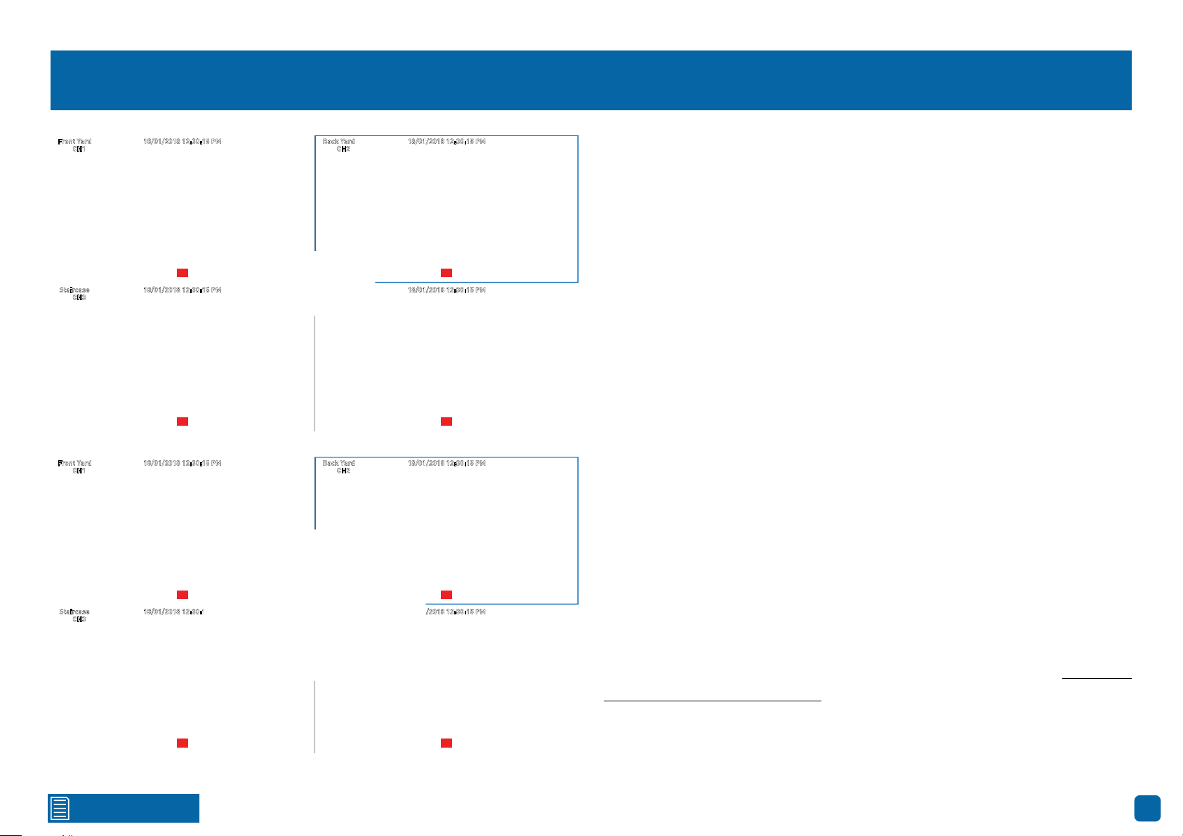
Password Recovery
18/01/2018 12:30:15 PMFront Yard
18/01/2018 12:30:15 PMBack Yard
18/01/2018 12:30:15 PMFront Yard
18/01/2018 12:30:15 PMBack Yard
CH1
CH3
CH1
CH3
CH2
Forgotten your password? Please do the following:
1. Right-click the mouse on the Live View screen to display the Menu Bar
then click “Main Menu”.
2. At the password login screen click “Forgot Password” then click “Yes”.
3. After a short moment, you will receive a password reset request email
PIRPIR
18/01/2018 12:30:15 PMStaircase
Side Gate
CH4
18/01/2018 12:30:15 PM
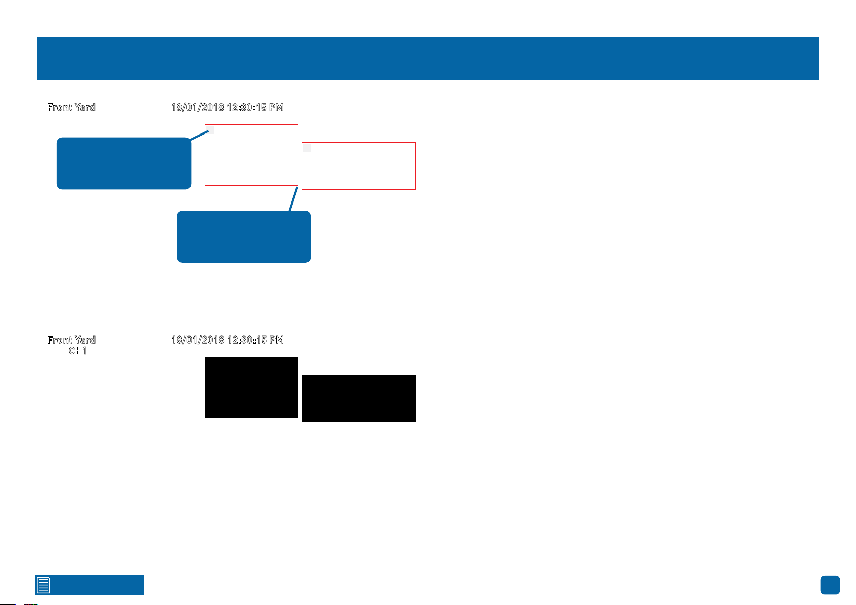
containing your NVR’s MAC address (if it’s not in your inbox, check your junk
or spam folder).
4. Input the MAC address including the semicolons (see left example) then
click “OK”.
5. A message will appear on-screen stating that your password has been
PIR PIR
reset. Click “OK” to continue.
6. Enter a new password (see bottom left example). The password has to
CH2
be a minimum of six characters and can contain a mixture of numbers and
letters. Use a password that you are familiar with, but is not easily known to
others.
7. Write down your password in the space provided below for safe keeping.
8. When finished click “Save”. A message will appear on-screen. Click “OK”
PIRPIR
18/01/2018 12:30:15 PMStaircase
Side Gate
CH4
18/01/2018 12:30:15 PM
to finish.
Don’t forget to write down your password: _________________________
PIR PIR
Click for contents
I haven’t created an email for my NVR, what can I do? Don’t worry, you can
use HomeSafe View to retrieve your recovery code (see page 106 - Password
Recovery using HomeSafe View).
3
Page 4

Contents
Important Information ������������������������������������������������������������������������������������������ 2
Password Recovery ����������������������������������������������������������������������������������������������� 3
Live View ���������������������������������������������������������������������������������������������������������������� 6
Live View Mode ������������������������������������������������������������������������������������������������������ 7
Live View Icons & Controls ����������������������������������������������������������������������������������� 8
Main Menu �������������������������������������������������������������������������������������������������������������� 9
Menu Layout ��������������������������������������������������������������������������������������������������������� 10
Camera Configuration ���������������������������������������������������������������������������������������11
Display: Live ��������������������������������������������������������������������������������������������������������� 12
Display: IP Channel ��������������������������������������������������������������������������������������������� 14
Display: Image Control ��������������������������������������������������������������������������������������� 15
Display: Privacy Zone ������������������������������������������������������������������������������������������ 18
Creating a Privacy Mask ������������������������������������������������������������������������������������� 19
Record: Mainstream (4K Camera)��������������������������������������������������������������������� 20
Record: Mainstream (5MP Camera) ����������������������������������������������������������������� 23
Record: Substream (4K Camera) ���������������������������������������������������������������������� 26
Device: PTZ ����������������������������������������������������������������������������������������������������������� 41
Controlling your PTZ Camera ���������������������������������������������������������������������������� 42
Creating a Preset ������������������������������������������������������������������������������������������������� 43
Analytics (4K Camera) ��������������������������������������������������������������������������������������� 44
Analytics: PID (Perimeter Intrusion Detection) ����������������������������������������������� 45
Drawing a Perimeter Intrusion Region ������������������������������������������������������������� 46
Analytics: LCD (Line Crossing Detection) ��������������������������������������������������������� 47
Drawing a Detection Line ����������������������������������������������������������������������������������� 48
Analytics: SOD (Stationary Object Detection) ��������������������������������������������������� 49
Drawing an Object Detection Region ���������������������������������������������������������������� 50
Analytics: PD (Pedestrian Detection) ���������������������������������������������������������������� 51
Drawing a Pedestrian Detection Region ���������������������������������������������������������� 52
Analytics: FD (Face Detection) ��������������������������������������������������������������������������� 53
Drawing a Face Detection Region ��������������������������������������������������������������������� 54
Analytics: CC (Cross Counting) �������������������������������������������������������������������������� 55
Drawing a Counting Line ������������������������������������������������������������������������������������ 56
Record: Substream (5MP Camera) ������������������������������������������������������������������� 28
Record: Mobilestream (4K Camera) ����������������������������������������������������������������� 30
Alarm: Motion ������������������������������������������������������������������������������������������������������ 32
Motion Detection Setup �������������������������������������������������������������������������������������� 34
Motion Detection Tips ����������������������������������������������������������������������������������������� 35
Thermal-Sensing Camera Tips ������������������������������������������������������������������������� 36
Alarm: Deterrent (Spotlight Security Camera) ������������������������������������������������ 37
Spotlight and Siren Detection Setup ����������������������������������������������������������������� 39
Spotlight and Siren Trigger Schedule ��������������������������������������������������������������� 40
Analytics: SD (Sound Detection) ������������������������������������������������������������������������ 57
Recording Configuration ����������������������������������������������������������������������������������� 58
Record: Record ����������������������������������������������������������������������������������������������������� 59
Record: Schedule ������������������������������������������������������������������������������������������������� 60
Capture: Capture ������������������������������������������������������������������������������������������������� 61
Capture: Schedule ����������������������������������������������������������������������������������������������� 62
Analytics: Schedule (4K Camera) ���������������������������������������������������������������������� 63
Playback & Backup ��������������������������������������������������������������������������������������������� 64
Search: General ��������������������������������������������������������������������������������������������������� 65
4
Page 5

Contents
Playback Interface ����������������������������������������������������������������������������������������������� 66
Search: Events (copy motion events to a USB drive) �������������������������������������� 68
Search: QuickShot (copy snapshots to a USB drive) ��������������������������������������� 69
Playing a Slideshow �������������������������������������������������������������������������������������������� 70
Search: QuickReview ������������������������������������������������������������������������������������������� 71
QuickReview Playback ���������������������������������������������������������������������������������������� 72
System Configuration ���������������������������������������������������������������������������������������� 74
Display: Output ����������������������������������������������������������������������������������������������������� 75
Network: Network ����������������������������������������������������������������������������������������������� 76
Network: Switch �������������������������������������������������������������������������������������������������� 78
Network: Email ���������������������������������������������������������������������������������������������������� 79
Network: Email Schedule (4K Camera) ����������������������������������������������������������� 80
Network: Email Schedule (5MP Camera) �������������������������������������������������������� 81
Network: DDNS ��������������������������������������������������������������������������������������������������� 82
Network: RTSP ���������������������������������������������������������������������������������������������������� 83
Device: HDD ���������������������������������������������������������������������������������������������������������� 84
System Status ������������������������������������������������������������������������������������������������������ 95
Search: Log ���������������������������������������������������������������������������������������������������������� 96
Search: Intelligent Analytics ������������������������������������������������������������������������������ 97
System: Info ���������������������������������������������������������������������������������������������������������� 98
System: Channel Info ������������������������������������������������������������������������������������������ 99
System: Record Info ������������������������������������������������������������������������������������������ 100
Glossary �������������������������������������������������������������������������������������������������������������� 101
Password Recovery using HomeSafe View ���������������������������������������������������� 106
Use Internet Explorer to connect to your NVR ���������������������������������������������� 108
Frequently Asked Questions ���������������������������������������������������������������������������� 109
Warranty Information ���������������������������������������������������������������������������������������� 110
Help & Resources ���������������������������������������������������������������������������������������������� 111
Device: S.M.A.R.T. ������������������������������������������������������������������������������������������������ 85
Device: Cloud �������������������������������������������������������������������������������������������������������� 86
System: General �������������������������������������������������������������������������������������������������� 87
System: DST ��������������������������������������������������������������������������������������������������������� 88
System: NTP ��������������������������������������������������������������������������������������������������������� 89
System: Users ������������������������������������������������������������������������������������������������������ 90
Advanced: Maintain ��������������������������������������������������������������������������������������������� 91
Advanced: Events ������������������������������������������������������������������������������������������������� 93
Advanced: Auto Upgrade ������������������������������������������������������������������������������������ 94
5
Page 6
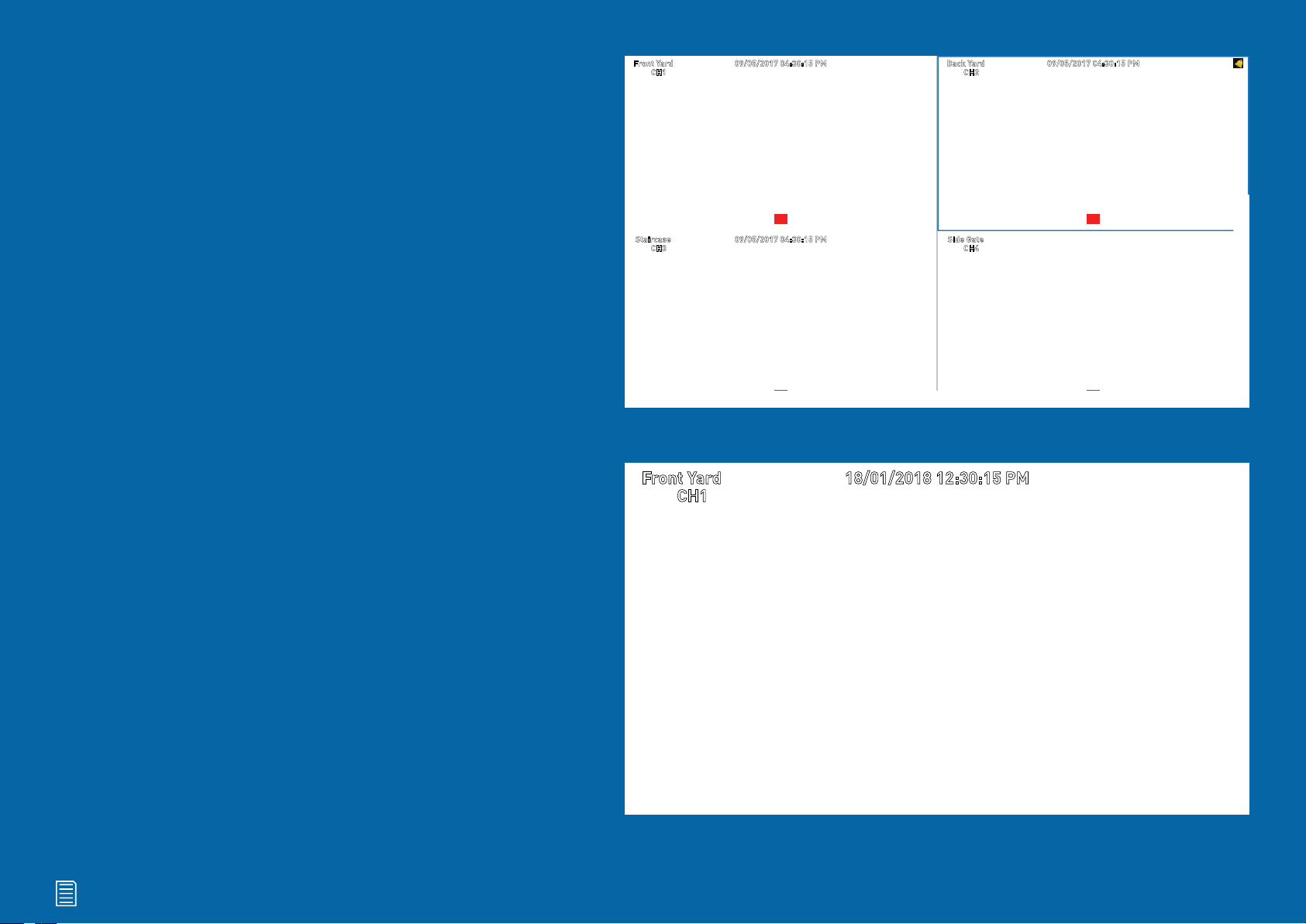
Live View
09/05/2017 04:30:15 PMFront Yard
09/05/2017 04:30:15 PMBack Yard
18/01/2018 12:30:15 PMFront Yard
Live View is the default display mode for
your NVR. Each camera connected will
be displayed on-screen. You can check
the status or operation of your NVR and
cameras using the icons and Menu Bar
CH1
CH3
CH2
PIRPIR
09/05/2017 04:30:15 PMStaircase
Side Gate
CH4
on the Live View screen. Right-click the
mouse to access the Menu Bar.
PIR PIR
CH1
Click for contents
6
Page 7
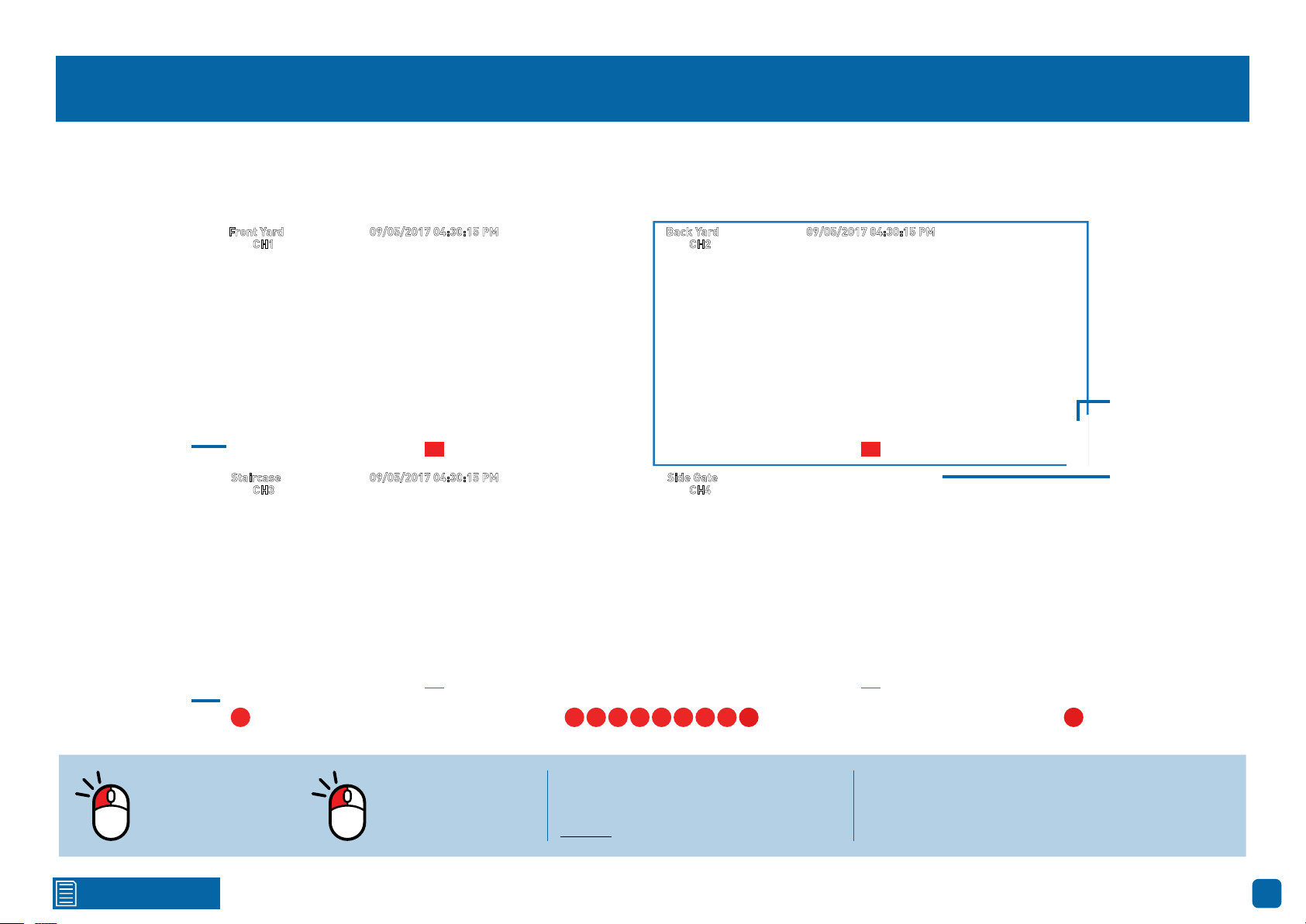
Live View Mode
09/05/2017 04:30:15 PMFront Yard
09/05/2017 04:30:15 PMBack Yard
Live View mode is the default display for your NVR. Each camera connected will be displayed (multiple view modes available). You can check the operation of
your NVR by using the status icons on the Live View screen. The date and time as well as the name for each camera is also displayed.
Status Icons
Menu Bar
CH1
09/05/2017 04:30:15 PMStaircase
CH3
PIR PIR
1 2113 4 95 6 7 8
CH2
Side Gate
CH4
Camera/Group
PIRPIR
Camera Toolbar
10
Double-click a live
video channel to
view full screen.
Click for contents
Click & drag a live
video channel to
reposition it.
Right-click the mouse in Live View
mode to display the Menu Bar (see
page 8 for more information).
Left-click a camera to access the Camera Toolbar. This provides access to functions such as
instant playback and to change image settings.
7
Page 8
Live View Icons & Controls
Menu Bar
1. Click this to open the Main Menu.
2. Lock your NVR to prevent access to the Main
Menu when “Menu Timeouts” is turned off.
3. Four camera view.
4. Nine camera view (this will display eight
cameras).
5. Click this to select from one of the mul-
ti-screen viewing modes available.
6. Click this to change from Mainstream to Sub-
stream when viewing the cameras in Live View
mode. Click again to change to Mainstream.
7. Click this to change the bitrate and frame rate
when viewing the cameras in Live View mode.
There are three profiles available - Real-time
(high bitrate/high frame rate), Balanced (a
balance between Real-time and Smooth), and
Smooth (high frame rate/low bitrate).
8. Click this to repeatedly cycle through each
channel full screen. Each channel will be displayed for five seconds.
9. Click this to change the volume or mute the
audio (click the speaker icon to mute).
10. Click this to access the Search menu.
11. Click this to access the Startup Wizard.
Please note: The 16 channel model will
have additional camera views available
(twelve camera and sixteen camera views).
To ensure the integrity of your recordings,
enter your password and click “Shutdown”
when powering off your NVR.
Status Icons
PIR
S
VIDEO LOSS
This icon indicates that the camera is being
recorded (either manually or by motion).
This icon indicates that your NVR is detecting motion from the camera.
This icon indicates that the camera has detected one or more warm objects.
This icon indicates that an event has occurred via one of the analytic functions.
Click this icon to display the analytic event
list (any analytic events that occur will be
listed here).
This icon indicates that the channel
doesn’t have a camera connected or
has lost the feed from its camera.
Click for contents
Camera/Group: When viewing a single
camera or a group of cameras, move the
mouse to the far left or right to reveal
the camera/group button. You can cycle
through each camera or group of cameras.
If you have a Spotlight Security Camera connected
to your NVR, you will see a “Spotlight” button on the
Camera Toolbar. This allows you to manually turn on
the spotlight and siren.
8
Page 9

Main Menu
The “Main Menu” is where you control the
various actions and options that are available
on your NVR. You can also access previous-
ly recorded video for playback and to copy to
a storage device such as a USB flash drive.
To maintain system integrity, a firmware up-
grade can be performed when available and
access to the “Shutdown” menu to restart or
safely turn off your NVR.
Click for contents
9
Page 10
Menu Layout
The various functions and options
available, are categorised on the lefthand side of the Menu.
To exit or access the
previous menu, rightclick the mouse.
Clicking each category will reveal a
number of tabs or sub-categories
that can be changed from their default setting.
Please note: The “Analytics” function in the
Main Menu, is only visible if one or more 4K
cameras are connected to your NVR.
Click for contents
Save changes that have been made
or restore default settings.
10
Page 11

Camera Configuration
The camera configuration options are avail-
able in the “Display”, “Record”, “Alarm” and
“Device” menus that are accessible from the
Main Menu. You can change the resolution,
bitrate, OSD (on-screen display) position as
well as image settings for hue, brightness,
contrast and saturation. Your NVR has con-
trols for detecting motion, allowing you to de-
fine specific areas to alert you to a potential
threat in and around your home. You also have
the ability to create one or more zones for pri-
vacy. If you have a Sensor Spotlight Camera
connected, you can enable the spotlight and
siren and change settings for both.
Click for contents
11
Page 12

Display: Live
The configuration options
available allow you to name
each camera relevant to
where it has been installed
as well as the ability to adjust image settings such as
brightness and contrast. You
can also change how the
date and time format are displayed in Live View mode.
Channel: Select a camera that you would like to edit.
Channel Name: Enter a name for the camera you’ve selected. It can be up to
eight characters in length.
Show Name: Leave this enabled to display the camera name in Live View
mode, otherwise click the drop down menu to disable.
Record Time: It’s recommended to leave this enabled, as a timestamp will
be embedded on all video recordings. This allows you to easily identify when
events have occurred. You can disable this if you wish.
· Don’t forget to click “Save”
to apply settings.
· Click the “Close” button to
exit the Main Menu.
time format selected for the NVR itself).
Refresh Rate: This setting correlates to the “Video Format” selection in the
Startup Wizard. When selecting “NTSC”, 60Hz will be displayed. When se-
lecting “PAL”, 50Hz will be displayed.
OSD Position: Allows you to change the position of the on-screen display on
the Live View screen. Click the “Setup” button then use the mouse to reposi-
tion. Right-click the mouse then click “Save”.
Color: Click the “Setup” button to access the image adjustment tools:
Date Format: Select a preferred display format (this is independent to the
date format selected for the NVR itself).
Time Format: Select a preferred display format (this is independent to the
Click for contents
→ Channel: Select a camera that you would like to edit.
→ Hue: This changes the color mix of the image.
(continued on next page)
12
Page 13

Display: Live
→ Bright: This changes how light the image appears to be.
· Don’t forget to click “Save”
to apply settings.
· Click the “Close” button to
exit the Main Menu.
→ Contrast: This increases the difference between the blackest black and
the whitest white in the image.
→ Saturation: This alters how much color is displayed in the image.
Use the slider to adjust each setting. Click the “Default” button to reset all
settings. When finished, click the “Save” button then click “Close” to exit.
Please note: Any changes made to the image settings available will af-
fect your recordings.
Click for contents
13
Page 14
Display: IP Channel
2
1
This function is an advanced feature that is used to manage the cameras
connected directly to your NVR as well as compatible IP cameras connected
to your router. In most circumstances, the functions available here will not be
needed for general use of your NVR.
When adding one or more cameras connected to your router, you need to
change Switch Mode to manual (see page 78 - Network: Switch).
1. Click this button “User-defined add” to add your network connected cam-
era.
2. After a short moment, your NVR will detect the camera and it will appear
as shown in the screenshot above-right. Click the checkbox to select.
3. Input the password (if required) and click the drop down menu to select the
channel that you would like to add the camera to.
Click for contents
3
4. Click this button “Add selected” to add the camera. A green status button
will appear indicating successful connection. Click the “Close” button to fin-
ish.
Please note: If you see “Off-line” in Live View mode for the camera that
you have added, this indicates that either a setting has changed (such as
password), or it has been physically disconnected from your router.
Can I add additional cameras that are connected to my router, even though
all the cameras inputs on my NVR are used?
When adding cameras that are connected to your router, it is assigned to an
available channel on your NVR, therefore if all channels are being used, you
cannot add additional cameras. You will have to disconnect one of the camer-
as connected to your NVR to add a router connected camera.
4
14
Page 15
Display: Image Control
The functions available enable you to control the appearance and characteristics
of the image shown from
each camera. Each function
can be adjusted to obtain the
best possible image quality,
providing you the flexibility
to install the camera in the
most challenging of lighting
situations.
Channel: Select a camera that you would like to edit.
IR-CUT Mode: Lets you choose how the camera handles color and how it
manages the transition from daytime to night-time and vice versa:
→ GPIO Auto: This will instruct the camera to switch automatically from
“Color Mode” to “Black White mode” and vice versa.
→ Color Mode: This will instruct the camera to operate in color mode only.
In low light conditions, the color will be quite faint. Image clarity will also
be reduced in low-light conditions.
→ Black White Mode: This will instruct the camera to operate in black &
white mode only.
IR-Cut Delay: Controls the delay of the IR cut filter when transitioning from
· Don’t forget to click “Save”
to apply settings.
· Click the “Close” button to
exit the Main Menu.
18/01/2018 12:30:15 PMFront Yard
daytime to night-time. The default setting will be suitable for most camera
locations but can be adjusted if needed. Click and hold the slider left or right
to change. The higher the number, the greater the delay.
Lens Flip & Angle Flip (4K camera): Turn the image upside down and/or
horizontally reverse the orientation of the image.
Angle Rotation (4K camera): Rotate the image by 90°, 180° and 270°.
Back Light: Improves exposure of an object that is in front of a light source.
This may happen if an object is in front of a window or if a person is coming
in from the outside. The camera will pick up the natural light, therefore the
object or person in the foreground becomes dark. If the camera is mounted
in a location where this is required, click the drop down menu to enable:
(continued on next page)
Click for contents
15
Page 16

Display: Image Control
· Don’t forget to click “Save”
to apply settings.
· Click the “Close” button to
exit the Main Menu.
18/01/2018 12:30:15 PMFront Yard
→ BLC (Back Light Compensation) Level: If “Back Light” has been enabled,
you will see this option available. Click the drop down menu to select the
level of back light compensation that you would like to apply. Some experimentation is recommended to select the best settings.
3D Noise Reduction: This function will reduce the overall noise content for
recordings done at night or in lower light conditions. The “Auto” selection will
be suitable for most camera locations but can be adjusted if needed:
→ Manual: Click the drop down menu and select “Manual”. Click and hold
the slider left or right to change. Just be aware that setting the value too
high, can cause a motion blur on moving objects appearing on-screen.
WDR (Wide Dynamic Range): This function will balance out images that have
a large dynamic range. It does this by brightening dark areas and darken-
Click for contents
ing bright areas. An example of this situation would be if an indoor camera
is pointing towards a window or building entrance. The image produced by
the camera during the day would be extremely washed out due to the high
brightness of the incoming light. If the camera is mounted in a location where
this is required, click the drop down menu to enable:
→ Level: Click and hold the slider left or right to change. The higher the
number, the wider the dynamic range will appear.
AGC (Automatic Gain Control): This function allows an increase in sensitivity,
enabling operation in lower light conditions. The camera will automatically
boost the gain control so that objects can be seen more clearly. Click the drop
down menu to select a level of control that you would like to apply.
(continued on next page)
16
Page 17
Display: Image Control
· Don’t forget to click “Save”
to apply settings.
· Click the “Close” button to
exit the Main Menu.
18/01/2018 12:30:15 PMFront Yard
White Balance: This function adjusts for lighting in order to make white ob-
jects appear white in photos. One of the indicators for an improper white
balance setting are dark colors which appear faded, shifted, or a completely
different color altogether. If this is happening, click the drop down menu and
change this to “Manual”, otherwise leave the “Auto” setting:
→ Manual: When selecting this mode, click and hold the red, green and blue
sliders left or right to change.
→ Indoor: Select this mode if the camera has been mounted inside a place
of residence.
Shutter: This function controls the length of time a camera’s shutter is open
and the amount of light reaching the sensor. In low light situations, the shutter needs to stay open longer in order for the sensor to receive enough light.
Click for contents
The “Auto” setting will be suitable for most camera locations but can be ad-
justed if needed:
→ Time Exposure: When selecting “Manual”, click the drop down menu to
select a different exposure time. The lower the number, the slower the
shutter speed (may cause a motion blur on moving objects). Some experimentation is recommended to select the best settings.
Defog Mode: This function extends visibility and improves video quality if
there is moderate to heavy fog or haze. The “Auto” setting will be suitable for
most camera locations. If selecting “Manual”, click and hold the slider left or
right to change.
Volume: Click and hold the slider left or right to change the camera’s built-in
microphone volume level.
17
Page 18
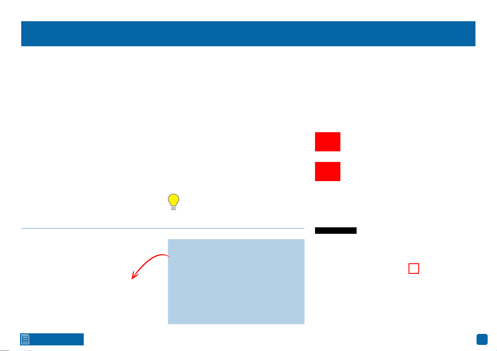
Display: Privacy Zone
This function can be used to
obscure all or part of your
image for privacy (up to four
privacy masks can be created per camera). You can also
use this to minimize false
triggers when motion is detected. Areas obscured by a
mask won’t be shown live or
recorded.
Channel: Select a camera that you would like to edit.
Mask Area: To create a mask, click the drop down menu to enable.
Area Setup: Click the checkbox on the number of privacy masks that you
want to create. Up to four privacy masks can be created per camera.
· Don’t forget to click “Save”
to apply settings.
· Click the “Close” button to
exit the Main Menu.
Mask Area: Click the “Setup” button to create one or more masks (see page
19 - Creating a Privacy Mask).
Click for contents
18
Page 19
Creating a Privacy Mask
18/01/2018 12:30:15 PMFront Yard
18/01/2018 12:30:15 PMFront Yard
1
Click and hold here to
reposition the mask to
the desired location.
2
1. Depending on the number of masks that you want to create, each mask
will be numbered. To reposition the mask, click and hold the mask number
then move the mask to the desired location.
2. To resize the mask, click and hold the bottom right corner of the mask then
resize to the desired size. You can reposition and resize each mask to overlap
each other.
CH1
Click and hold here to
resize the mask to the
desired size.
In the example provided on the left, two masks have been created to block
out cars and pedestrians adjacent to the front yard of the house. This will
minimise false triggers and block movement that is not relevant to entry via
the front entrance.
3. When finished, right-click to exit then click “Save” to apply. Areas obscured
by a mask won’t be shown live or recorded (see below left).
To remove a mask, uncheck the relevant checkbox next to “Area Setup” then
click “Save” to apply.
Click for contents
19
Page 20

Record: Mainstream (4K Camera)
The functions available allow
you to change the resolution,
frame rate and bitrate for
each camera connected. By
default the recording resolution, frame rate and bitrate
are automatically selected to
fit in with the capabilities of
the provided cameras, however you can change them if
required.
Channel: Select a camera that you would like to edit.
Resolution: By default the recording resolution is automatically selected to
match the capabilities of the provided cameras. Lower resolutions are available to select if required.
FPS: The number of frames per second (fps) that your NVR will record. The
default is 15fps, however you can change this if needed. In the HomeSafe
View app, you can select “Mainstream” in Live mode to view your cameras.
Lower the frame rate if you’re having issues streaming to your mobile device
(lowering the frame rate to 7fps for example, will reduce the bandwidth required without sacrificing image quality).
Video Encode Type: Your NVR utilizes two encoding methods to record vid-
eo. The default method of compression is H.265. This will result in less hard
· Don’t forget to click “Save”
to apply settings.
· Use the “Copy” function to
apply all settings to the other
cameras.
· Click the “Close” button to
exit the Main Menu.
drive space used when recording (before older videos are automatically over-
written) and will consume less bandwidth when using the remote playback
feature in the HomeSafe View app. The second method of compression is
H.264. This is a commonly used format for recording and compressing video
and is used in Blu-ray players and to broadcast TV signals. If visual quality is
of importance, change this to H.264, otherwise leave the default selection.
Bitrate Control: CBR (Constant Bitrate) utilises a fixed bitrate and band-
width to record video. This means your NVR will use the same number of bits
throughout the entire recording, regardless of what is happening on-screen.
VBR (Variable Bitrate) utilises a bitrate that will increase or decrease, de-
pending on how complex the scene is, to record video.
(continued on next page)
Click for contents
20
Page 21

Record: Mainstream (4K Camera)
· Don’t forget to click “Save”
to apply settings.
· Use the “Copy” function to
apply all settings to the other
cameras.
· Click the “Close” button to
exit the Main Menu.
Which method should I choose? Scene complexity can vary significantly over
several hours of recorded video, and the bitrate you select for recording will
have an effect on image quality, bandwidth consumption, and hard drive storage. A complex scene with moving action, such as traffic on a city street, or a
scene with a lot of contrasting colors, will affect image quality and bandwidth
consumption more than a less complex scene with little action or movement.
CBR: This is the default method of control that your NVR will use to record
video. If you have cameras placed in high traffic areas, CBR is the recommended control method. As the bitrate is fixed, the image quality will be consistent throughout the entire recording.
VBR: If you have cameras placed in low traffic areas, VBR is the recommend-
ed control method. As the bitrate is variable, your NVR can use a lower bitrate
Click for contents
if there is little to no movement detected. This will result in a lower recording
size as well as a lower bandwidth requirement.
When choosing VBR, you can select the recording quality that will define the
variable bitrate used. You can select from lowest to highest.
Bitrate Mode: You have the choice of selecting a predefined or user-defined
bitrate. For most instances, the default selection will be suitable.
Bitrate: The amount of data that your NVR will use to record video. The high-
er the bitrate, the more space each recording will consume on the hard drive.
The default bitrate is 6144Kbps. Change the bitrate if you’re having issues
streaming to your mobile device via the HomeSafe View app (when selecting
“Mainstream” in Live mode to view your cameras).
(continued on next page)
21
Page 22

Record: Mainstream (4K Camera)
Decreasing this will consume less bandwidth when streaming.
· Don’t forget to click “Save”
to apply settings.
· Use the “Copy” function to
apply all settings to the other
cameras.
· Click the “Close” button to
exit the Main Menu.
Audio: By default, your NVR will record audio using the camera’s built-in mi-
crophone. If this is not required, click the checkbox to disable.
Please note: Selecting the appropriate recording settings is dependent
on camera location, lighting conditions and the level of quality required.
Some experimentation is recommended to select the best settings.
Click for contents
22
Page 23

Record: Mainstream (5MP Camera)
The functions available allow
you to change the resolution,
frame rate and bitrate for
each camera connected. By
default the recording resolution, frame rate and bitrate
are automatically selected to
fit in with the capabilities of
the provided cameras, however you can change them if
required.
Channel: Select a camera that you would like to edit.
Resolution: By default the recording resolution is automatically selected to
match the capabilities of the provided cameras. Lower resolutions are available to select if required.
FPS: The number of frames per second (fps) that your NVR will record. The
default is 15fps, however you can change this if needed. In the HomeSafe
View app, you can select “Mainstream” in Live mode to view your cameras.
Lower the frame rate if you’re having issues streaming to your mobile device
(lowering the frame rate to 7fps for example, will reduce the bandwidth required without sacrificing image quality).
Video Encode Type: Your NVR utilizes two encoding methods to record vid-
eo. The default method of compression is H.265. This will result in less hard
· Don’t forget to click “Save”
to apply settings.
· Use the “Copy” function to
apply all settings to the other
cameras.
· Click the “Close” button to
exit the Main Menu.
drive space used when recording (before older videos are automatically over-
written) and will consume less bandwidth when using the remote playback
feature in the HomeSafe View app. The second method of compression is
H.264. This is a commonly used format for recording and compressing video
and is used in Blu-ray players and to broadcast TV signals. If visual quality is
of importance, change this to H.264, otherwise leave the default selection.
Bitrate Control: CBR (Constant Bitrate) utilises a fixed bitrate and band-
width to record video. This means your NVR will use the same number of bits
throughout the entire recording, regardless of what is happening on-screen.
VBR (Variable Bitrate) utilises a bitrate that will increase or decrease, de-
pending on how complex the scene is, to record video.
(continued on next page)
Click for contents
23
Page 24

Record: Mainstream (5MP Camera)
· Don’t forget to click “Save”
to apply settings.
· Use the “Copy” function to
apply all settings to the other
cameras.
· Click the “Close” button to
exit the Main Menu.
Which method should I choose? Scene complexity can vary significantly over
several hours of recorded video, and the bitrate you select for recording will
have an effect on image quality, bandwidth consumption, and hard drive storage. A complex scene with moving action, such as traffic on a city street, or a
scene with a lot of contrasting colors, will affect image quality and bandwidth
consumption more than a less complex scene with little action or movement.
CBR: This is the default method of control that your NVR will use to record
video. If you have cameras placed in high traffic areas, CBR is the recommended control method. As the bitrate is fixed, the image quality will be consistent throughout the entire recording.
VBR: If you have cameras placed in low traffic areas, VBR is the recommend-
ed control method. As the bitrate is variable, your NVR can use a lower bitrate
Click for contents
if there is little to no movement detected. This will result in a lower recording
size as well as a lower bandwidth requirement.
When choosing VBR, you can select the recording quality that will define the
variable bitrate used. You can select from lowest to highest.
Bitrate Mode: You have the choice of selecting a predefined or user-defined
bitrate. For most instances, the default selection will be suitable.
Bitrate: The amount of data that your NVR will use to record video. The high-
er the bitrate, the more space each recording will consume on the hard drive.
The default bitrate is 4096Kbps. Change the bitrate if you’re having issues
streaming to your mobile device via the HomeSafe View app (when selecting
“Mainstream” in Live mode to view your cameras).
(continued on next page)
24
Page 25

Record: Mainstream (5MP Camera)
Decreasing this will consume less bandwidth when streaming.
· Don’t forget to click “Save”
to apply settings.
· Use the “Copy” function to
apply all settings to the other
cameras.
· Click the “Close” button to
exit the Main Menu.
Audio: By default, your NVR will record audio using the camera’s built-in mi-
crophone. If this is not required, click the checkbox to disable.
Please note: Selecting the appropriate recording settings is dependent
on camera location, lighting conditions and the level of quality required.
Some experimentation is recommended to select the best settings.
Click for contents
25
Page 26

Record: Substream (4K Camera)
The functions available allow you to control how video
is streamed to your mobile
device and computer using
the HomeSafe View app and
software. You can also click
“Stream switch” to change
to Substream in Live View
mode. You can change the
resolution, frame rate, bitrate control and bitrate if
you’re having issues streaming live video from your NVR.
Channel: Select a camera that you would like to edit.
Resolution: The default resolution is 1280 x 720. You can select a lower res-
olution if you’re having issues streaming to your mobile device via the HomeSafe View app (especially when viewing multiple cameras).
FPS: The number of frames per second (fps) that your NVR will process when
streaming to your mobile device and computer via HomeSafe View. For most
instances, the default frame rate (15fps) will be suitable. This is especially
the case for cameras that monitor medium to high traffic areas and will result in smoother motion, but just be aware this will increase the bandwidth
required. You can lower this if monitoring low traffic areas.
Video Encode Type: Your NVR utilizes two encoding methods to record video.
The default method of compression is H.264. This is a commonly used format
· Don’t forget to click “Save”
to apply settings.
· Use the “Copy” function to
apply all settings to the other
cameras.
· Click the “Close” button to
exit the Main Menu.
for recording and compressing video and is used in Blu-ray players and to
broadcast TV signals. The second method of compression is H.265. This will
result in less hard drive space used when recording (before older videos are
automatically overwritten) and will consume less bandwidth when using the
remote playback feature in the HomeSafe View app. If this is of importance,
change this to H.265, otherwise leave the default selection.
Bitrate Control: Change this to VBR. This will result in a lower recording size
as well as a lower bandwidth requirement. You can select the recording qual-
ity that will define the variable bitrate used, from lowest to highest.
Bitrate Mode: You have the choice of selecting a predefined or user-defined
bitrate. For most instances, the default selection will be suitable.
(continued on next page)
Click for contents
26
Page 27

Record: Substream (4K Camera)
Bitrate: The amount of data that your NVR will use to stream video to your
mobile device. For cameras that monitor medium to high traffic areas, increase the bitrate to add more detail to the camera’s image, but just be aware
this will increase the bandwidth required. Increase the bitrate in small doses
until you are satisfied with the image quality.
· Don’t forget to click “Save”
to apply settings.
· Use the “Copy” function to
apply all settings to the other
cameras.
· Click the “Close” button to
exit the Main Menu.
Audio: By default, your NVR will record audio using the camera’s built-in mi-
crophone. If this is not required, click the checkbox to disable.
Please note: When streaming live video, the overall quality is dependent
on your internet connection and the Substream settings utilised. This is
important to note when streaming multiple cameras at the same time.
Click for contents
27
Page 28

Record: Substream (5MP Camera)
The functions available allow you to control how video
is streamed to your mobile
device and computer using
the HomeSafe View app and
software. You can also click
“Stream switch” to change
to Substream in Live View
mode. You can change the
resolution, frame rate, bitrate control and bitrate if
you’re having issues streaming live video from your NVR.
Channel: Select a camera that you would like to edit.
Resolution: The default resolution is 640 x 480. You can select a lower resolu-
tion if you’re having issues streaming to your mobile device via the HomeSafe
View app (especially when viewing multiple cameras).
FPS: The number of frames per second (fps) that your NVR will process when
streaming to your mobile device and computer via HomeSafe View. For most
instances, the default frame rate (15fps) will be suitable. This is especially
the case for cameras that monitor medium to high traffic areas and will result in smoother motion, but just be aware this will increase the bandwidth
required. You can lower this if monitoring low traffic areas.
Video Encode Type: Your NVR utilizes two encoding methods to record video.
The default method of compression is H.264. This is a commonly used format
· Don’t forget to click “Save”
to apply settings.
· Use the “Copy” function to
apply all settings to the other
cameras.
· Click the “Close” button to
exit the Main Menu.
for recording and compressing video and is used in Blu-ray players and to
broadcast TV signals. The second method of compression is H.265. This will
result in less hard drive space used when recording (before older videos are
automatically overwritten) and will consume less bandwidth when using the
remote playback feature in the HomeSafe View app. If this is of importance,
change this to H.265, otherwise leave the default selection.
Bitrate Control: Change this to VBR. This will result in a lower recording size
as well as a lower bandwidth requirement. You can select the recording qual-
ity that will define the variable bitrate used, from lowest to highest.
Bitrate Mode: You have the choice of selecting a predefined or user-defined
bitrate. For most instances, the default selection will be suitable.
(continued on next page)
Click for contents
28
Page 29

Record: Substream (5MP Camera)
Bitrate: The amount of data that your NVR will use to stream video to your
mobile device. For cameras that monitor medium to high traffic areas, increase the bitrate to add more detail to the camera’s image, but just be aware
this will increase the bandwidth required. Increase the bitrate in small doses
until you are satisfied with the image quality.
· Don’t forget to click “Save”
to apply settings.
· Use the “Copy” function to
apply all settings to the other
cameras.
· Click the “Close” button to
exit the Main Menu.
Audio: By default, your NVR will record audio using the camera’s built-in mi-
crophone. If this is not required, click the checkbox to disable.
Please note: When streaming live video, the overall quality is dependent
on your internet connection and the Substream settings utilised. This is
important to note when streaming multiple cameras at the same time.
Click for contents
29
Page 30

Record: Mobilestream (4K Camera)
Mobilestream is the default control method used to
stream video to your mobile
device and computer using
the HomeSafe View app and
software. You can change
the resolution, frame rate,
bitrate control and bitrate if
you’re having issues streaming live video from your NVR.
Channel: Select a camera that you would like to edit.
Enable: It’s strongly recommended leaving this option enabled as there is no
benefit if it is disabled (if disabled, Substream will be used to stream video).
Resolution: The default resolution is 640 x 480. You can select a lower resolu-
tion if you’re having issues streaming to your mobile device via the HomeSafe
View app (especially when viewing multiple cameras).
FPS: The number of frames per second (fps) that your NVR will process when
streaming to your mobile device and computer via HomeSafe View. For most
instances, the default frame rate (10fps) will be suitable. This is especially
the case for cameras that monitor medium to high traffic areas and will result in smoother motion, but just be aware this will increase the bandwidth
required. You can lower this if monitoring low traffic areas.
· Don’t forget to click “Save”
to apply settings.
· Use the “Copy” function to
apply all settings to the other
cameras.
· Click the “Close” button to
exit the Main Menu.
Video Encode Type: Your NVR utilizes two encoding methods to record video.
The default method of compression is H.264. This is a commonly used format
for recording and compressing video and is used in Blu-ray players and to
broadcast TV signals. The second method of compression is H.265. This will
result in less hard drive space used when recording (before older videos are
automatically overwritten) and will consume less bandwidth when using the
remote playback feature in the HomeSafe View app. If this is of importance,
change this to H.265, otherwise leave the default selection.
Bitrate Control: Change this to VBR. This will result in a lower recording size
as well as a lower bandwidth requirement. You can select the recording qual-
ity that will define the variable bitrate used, from lowest to highest.
(continued on next page)
Click for contents
30
Page 31

Record: Mobilestream (4K Camera)
Bitrate Mode: You have the choice of selecting a predefined or user-defined
bitrate. For most instances, the default selection will be suitable.
· Don’t forget to click “Save”
to apply settings.
· Use the “Copy” function to
apply all settings to the other
cameras.
· Click the “Close” button to
exit the Main Menu.
Bitrate: The amount of data that your NVR will use to stream video to your
mobile device. For cameras that monitor medium to high traffic areas, increase the bitrate to add more detail to the camera’s image, but just be aware
this will increase the bandwidth required. Increase the bitrate in small doses
until you are satisfied with the image quality.
Audio: By default, your NVR will record audio using the camera’s built-in mi-
crophone. If this is not required, click the checkbox to disable.
Please note: When streaming live video, the overall quality is dependent
on your internet connection and the Mobilestream settings utilised. This
is important to note when streaming multiple cameras at the same time.
Click for contents
31
Page 32

Alarm: Motion
When motion has been detected by one or more cameras, your NVR will alert you
to a potential threat at your
home. It does this by sending you an email alert with
an attached image from the
camera to use as a reference
(if this option is enabled) and/
or sending push notifications
via the HomeSafe View app.
Channel: Select a camera that you would like to edit.
Detection: By default, your NVR will record motion only if one or more objects
have been detected by the camera and the camera’s built-in PIR sensor. This
provides more accurate motion detection by eliminating false triggers due to
wind, leaves falling and rain (see page 36 - Thermal-Sensing Camera Tips).
If you’re monitoring an area that doesn’t require objects to be detected by the
camera’s built-in PIR sensor, such as a busy walkway or a building entrance,
change this to “Motion”.
Buzzer: When motion has been detected, you can enable the NVR’s buzzer to
alert you for a predetermined amount of time.
Sensitivity: This option allows you to change the sensitivity level. The higher
the number, the more sensitive your NVR will be when detecting motion. For
· Don’t forget to click “Save”
to apply settings.
· Click the “Close” button to
exit the Main Menu.
If you have a Spotlight Security
Camera connected to your NVR,
you will see a “Deterrent” tab (see
page 37 - Alarm: Deterrent” for
further instructions.
most instances, the default selection will be suitable, however it’s recom-
mended to conduct a test to see if the sensitivity level is correct for the cam-
era’s location (see page 35 - Motion Detection Tips).
Area: Click the “Setup” button to change the default motion detection area.
The entire view of the camera is enabled for motion detection, however you
can select certain areas if you wish (see page 34 - Motion Detection Setup).
Post Recording: This option instructs your NVR to record for a set period of
time after an event has occurred. For most instances, the default selection
will be suitable, however you can change this if you wish.
Show Message: When motion has been detected, the motion icon will appear
on-screen. Click the checkbox if you want to disable this.
(continued on next page)
Click for contents
32
Page 33

Alarm: Motion
· Don’t forget to click “Save”
to apply settings.
· Click the “Close” button to
exit the Main Menu.
Send Email: Click the checkbox to enable your NVR to send an email alert
when motion has been detected.
Full Screen: Click the checkbox if you would like to view the camera full
screen in Live View mode when motion has been detected.
Push: Click the checkbox to receive notifications via the HomeSafe View app
(alarm notification has to be enabled within the app - see “Alarm Mode” in the
HomeSafe View manual for more information).
Send to Cloud: Click the checkbox to copy snapshots to the cloud via Dropbox
(see page 86 - Device: Cloud).
Record Channel: This option instructs your NVR to trigger additional camer-
as to start recording when motion has been detected. Click the checkbox to
select all cameras or click on the individual camera number to trigger.
Click for contents
Please note: The “Push” and “Send to Cloud” options are only available
when thermal-sensing cameras are connected to your NVR. When selecting “Motion” for the detection type, these two options are not available to
select.
33
Page 34

Motion Detection Setup
To delete the default
motion detection area,
place your mouse here.
1. Place the mouse inside the cell or square surrounded by a yellow border (as
illustrated on the left). Press and hold the left mouse button, click and drag
to the bottom right-hand corner then release the mouse. This will delete the
default motion detection area.
2. To create a new motion detection area, select the cell or square that you
want to start at. Press and hold the left mouse button, click and drag to select
the area that you want to create then release the mouse.
3. Multiple areas can be created. Each individual cell or square can be enabled
to detect motion. The same action also applies to delete an area that has been
created.
In the example provided, a motion detection area has been created for the
front yard but excludes objects such as trees as well as cars and pedestrians
adjacent to the front yard of the house. Anyone who walks along the path via
the front entrance and approaches the front door will be detected.
Movement outside of the motion detection areas will not be detected so will
not trigger recordings or event notifications.
Each individual cell or
square can be enabled
to detect motion.
Click for contents
4. Right-click the mouse to exit. Adjust the sensitivity if required.
5. Click the “Save” button to save changes made.
34
Page 35

Motion Detection Tips
Placement of the cameras
1. Place cameras so they are facing areas where people have to walk through to approach your home
regardless of where they are headed. A good idea is to place a camera overlooking your front door
to capture an image of anyone approaching it for later reference. This is great if you have parcels
delivered to your door or if the potential burglar knocks or rings the doorbell to see if anyone is home.
2. Walk around your house and assess where intruders are most likely to approach to enter, and what
path they would take. Most burglars enter the home through a front or back door, so it’s advisable
to place the cameras near those areas so that you get the best amount of detail of anyone who
approaches.
3. When installing cameras outside, it’s important to keep your front and backyard as well-lit as
possible for ideal night vision and the ability to detect motion. It’s common for intruders to enter a
home through an unlocked garage or by using a garage door opener in an unlocked car located in
the driveway. Positioning your cameras to overlook cars in the driveway and similar locations can be
very useful.
Avoiding False Triggers
1. A tree, shrub or foliage that is blown by the wind - angle the camera so wind-blown objects are out
of the camera’s view or use the camera motion detection area settings to exclude these areas from
detection.
2. People moving along sidewalks or streets that are close to your home, aim your cameras and use
the motion detection area settings to ensure only legitimate threats are triggering events.
3. Vehicles moving in the background - angle the camera so as to avoid movement in the background
or use the motion detection area settings to stop detection of cars in the street.
4. Movement or light reflected off smooth surfaces such as glass - adjust the sensitivity level and/or
avoid pointing the camera directly at glass surfaces.
Click for contents
The red cameras illustrated (see above) are your
primary locations. Place your cameras close to
the front door, back door, garage entrance and
overlooking the backyard.
The blue cameras illustrated are your secondary
locations. If your NVR includes additional cameras, place these at the front entrance inside the
home, the front of the house (this could overlook
the front garden or driveway), a side gate or if you
have multiple entrances to the backyard.
35
Page 36

Thermal-Sensing Camera Tips
Your cameras have a built-in PIR (passive infrared motion detector) sensor. This means they can
sense movement of warm objects including people, cars and animals. The advantage over cameras
that don’t have a PIR sensor, is they are very resistant to false triggers from changes in the image.
→ PIR sensors work best when an intruder walks parallel or is passing across their “field of view”
as opposed to walking directly at them. For example, in a hallway or path around the house you
tend to walk parallel to the walls, not directly toward them. Position your cameras so that anyone
approaching your home will cross the camera’s view and trigger an event.
→ For a recording to occur, the PIR must sense a warm object moving in front of it and the camera’s
image sensor must detect movement in the image. If either of these triggers has not occurred,
no video will be recorded.
→ When the PIR is triggered, the PIR icon (red box) will flash on-screen. If PIR and motion are trig-
gered, the “running man” icon will be shown on-screen indicating that an event has occurred and
that a recording is happening.
→ The PIR can detect objects outside of the camera’s field of view, so not everything that triggers the
sensor will be visible on your camera.
→ The PIR can reliably detect movement up to 30ft/9m, movement beyond this range may or may
not be detected.
→ Be aware that sudden changes in temperature of paths, roads, for example, can cause some mi-
nor false alerts to occur when there is also movement in the image such as trees and shadows.
→ If some false triggering is occurring, use the motion area setup to remove moving objects from
being detected, and to further refine your alerts (see page 34 - Motion Detection Setup).
→ When used indoors, keep the cameras away from heating vents, heaters and other heat sources
as they can trigger the PIR. However if there is no movement in the image, a false alert is unlikely.
When installing cameras outside, mount them
where intruders are most likely to enter (front &
back doors, garage entrance). Angle the cameras so the intruder walks parallel to the sensor.
PIR sensors work best when an intruder walks
parallel or is passing across their “field of view”
as opposed to walking directly at them.
Click for contents
36
Page 37

Alarm: Deterrent (Spotlight Security Camera)
· Don’t forget to click “Save”
to apply settings.
· Click the “Default” button to
revert back to default settings.
· Click the “Close” button to
exit the Main Menu.
WARNING: The “Strobe” function
may trigger seizures for people
with photosensitive epilepsy. User
discretion is advised.
Channel: Select a camera that you would like to edit.
Enable: The camera’s spotlight is enabled by default. If the spotlight is not
required, click the drop down menu to disable.
Light Level: Click and hold the slider left or right to adjust the spotlight’s light
level. The higher the number, the brighter the spotlight will appear. Adjust
accordingly.
Light Mode: Lets you choose how the spotlight operates when motion has
been detected. By default, the spotlight will turn on and remain lit for the
light duration selected (see below). The second option instructs the spotlight
to flash continually (a strobe effect) for the light duration selected. Click the
drop down menu to change.
Light Duration: Lets you change the length of time the spotlight will either
Click for contents
remain lit or flash continually when motion has been detected (depending on
the light mode selected). Adjust accordingly.
Siren: The camera’s siren is disabled by default. If the siren is required, click
the drop down menu to enable. A warning message will appear on-screen.
Click “OK” to continue.
Siren Level: Click and hold the slider left or right to adjust the siren’s audio
level. The higher the number, the louder the siren will be.
Siren Duration: Lets you change the length of time the siren will remain
turned on when motion has been detected. Adjust accordingly.
(continued on next page)
37
Page 38

Alarm: Deterrent (Spotlight Security Camera)
Sensitivity: This option allows you to change how sensitive the spotlight and
siren will be when your NVR has detected motion. This is independent of the
camera’s sensitivity for detecting motion. As an example, you may want to
record movement that is happening in the background but you don’t want the
spotlight and or the siren to be triggered until one or more objects gets closer to the camera. For this scenario, you would adjust the sensitivity to 1 or 2.
Some experimentation is recommended to select the best settings.
· Don’t forget to click “Save”
to apply settings.
· Click the “Default” button to
revert back to default settings.
· Click the “Close” button to
exit the Main Menu.
WARNING: The “Strobe” function
may trigger seizures for people
with photosensitive epilepsy. User
discretion is advised.
Area: Click the “Setup” button to change the default spotlight and siren de-
tection area. The entire view of the camera is enabled, however you can select
certain areas if you wish (see page 39 - Spotlight and Siren Detection Setup).
Schedule: Click the “Setup” button to change the default spotlight and siren
trigger schedule (see page 40 - Spotlight and Siren Trigger Schedule).
Click for contents
38
Page 39

Spotlight and Siren Detection Setup
1. Place the mouse inside the cell or square surrounded by a yellow border (as
To delete the default
spotlight and siren detection area, place your
mouse here.
illustrated on the left). Press and hold the left mouse button, click and drag
to the bottom right-hand corner then release the mouse. This will delete the
default spotlight and siren detection area.
2. To create a spotlight and siren motion detection area, select the cell or
square that you want to start at. Press and hold the left mouse button, click
and drag to select the area that you want to create then release the mouse.
3. Multiple areas can be created. Each individual square can be enabled to
trigger the spotlight and siren. The same action also applies to delete an area
that has been created.
In the example provided, a spotlight and siren detection area has been created
for the backyard and will trigger the spotlight and siren when one or more
objects gets closer to the rear of the house.
Movement outside of the spotlight and siren detection area will not trigger the
spotlight and siren.
Each individual square
can be enabled to trigger
the spotlight and siren.
Click for contents
4. Right-click the mouse to exit. Adjust the sensitivity if required.
5. Click the “Save” button to save changes made.
39
Page 40

Spotlight and Siren Trigger Schedule
By default, the spotlight and siren will not trigger between 06:30 a.m. and
04:30 p.m., however you can change this according to your needs.
Each square represents 30 minutes. Using the mouse, click on a particular
square to change or click and drag the mouse over the squares corresponding to your desired time period.
Click the “Save” button to save changes made.
Click for contents
40
Page 41

Device: PTZ
If you have a compatible PTZ camera connected to your NVR, you can use the
PTZ controls to move the camera as well as the ability to zoom into an object
and to control the level of focus (if available). You can create multiple preset
positions, which can be recalled to focus the camera’s view to a different position. Cruise mode can also be used to move the camera to different preset
positions that have been created.
· Don’t forget to click “Save”
to apply settings.
· Use the “Copy” function to
apply all settings to the other
cameras.
· Click the “Close” button to
exit the Main Menu.
To configure your PTZ camera, consult the instruction manual included with
your device then match those settings here.
For instructions on how to control your PTZ camera and creating preset positions (see page 42 - Controlling your PTZ Camera).
Click for contents
41
Page 42

Controlling your PTZ Camera
18/01/2018 12:30:15 PMBack Yard
CH2
1 2 3
4
56
The 8580 series supports the Onvif protocol, allowing connection of nonSwann PTZ compatible cameras (some functions may not be available).
To move the PTZ con-
trols, click and hold then
reposition it.
To control your PTZ camera, in Live View mode click on the channel the camera is connected to then click the “PTZ” button located on the camera toolbar. The channel will go full screen and the PTZ controls will be visible (as
shown on the left).
1. If you have multiple PTZ cameras connected, click this to select a different
camera.
2. Click this to start cruise mode (preset positions must be created first).
Cruise mode instructs your NVR to automatically move the camera according to the preset positions that have been created. Click again to stop cruise
mode.
3. Adjust the speed control to alter how fast or slow the camera will pan or
tilt. Move the slider to decrease or increase the speed.
4. Click this to access the Preset panel. This allows you to create multiple
preset positions and to access the camera’s on-screen display. Click again
to close.
Click for contents
5. This allows you to zoom into an object and to control the level of focus (de-
pending on the camera you have, the iris control may not be available).
6. Click the directional buttons to move the camera in the direction selected
(the middle button has no function).
For instructions on how to create a preset and to access the camera’s onscreen display (see page 43 - Creating a Preset).
42
Page 43

Creating a Preset
18/01/2018 12:30:15 PMBack Yard
CH2
Creating a Preset
→ To create a preset, use the PTZ controls to move the camera to the de-
sired focal position. The zoom and focus controls can also be used. Use
the speed control to alter how fast or slow the camera will move.
→ Change the length of time the camera will stay at this position.
1
2
56
5 6
3
4
1. Each preset position will have a different number assigned to it. To recall
a particular position, click the dialogue box, input a number then click “GO
TO”. The camera will then move to that particular position. When creating
a preset position, you may want to make note which position is assigned to
each number.
2. Click the dialogue box to change the length of time (in seconds) the camera
will stay at a particular position, before moving to the next position.
3. Click this to go to a particular preset position.
4. Click this to create a preset.
5. Click this to save any changes made.
→ Click the “Set” button to create the preset. You will notice that the preset
position will increase each time a preset is created. The total number of
presets created will also be displayed. Up to 255 different preset positions
can be created.
→ Repeat these steps to create multiple preset positions. When finished,
click the “Save” button to save. Right-click to exit.
→ Click the “Start Cruise” button to continually cycle through each preset
created. Click again to stop.
Accessing your Camera’s On-screen Display
→ Click the preset position dialogue box (1) then click the backspace button
twice. Enter “95”, click the enter button then click the “GO TO” button.
→ To navigate the on-screen display, click the up and down directional but-
tons. The hyphen indicates which option or setting has been selected.
→ Click the right directional button to confirm selection. Click the left and
right directional buttons to change settings within sub-menus.
→ Consult the camera’s instruction manual for information about the func-
tions available in the on-screen display.
6. Click this to clear a preset.
Click for contents
Please note: If the above instructions don’t work for your camera, try
pressing the Iris “+” button to access the on-screen display.
43
Page 44

Analytics (4K Camera)
Analytics provides you with much great-
er control on how your NVR detects mo-
tion. You can enable face detection, be
alerted if the camera detects static ob-
jects removed or left behind, and to count
movement crossing a line that you draw
on the image. By drawing a detection
line, you can apply a rule on which direc-
tion your NVR detects motion, and you
can also define specific intrusion areas
that can alert you if one or more objects
has stayed within a given time (especial-
ly helpful if people are loitering or if a car
is parked where it shouldn’t be).
Click for contents
44
Page 45

Analytics: PID (Perimeter Intrusion Detection)
A perimeter intrusion region
can be used to define specific
areas that you want to monitor for motion. For example,
a rule can be defined so that
your NVR will alert you if one
or more objects have stayed
within the intrusion region
for a particular time. You can
also select which direction
an object can enter and or
exit the region defined.
Channel: Select a camera that you would like to edit.
Enable: Two choices are available. Select “PID” to receive alerts when mo-
tion has been detected. Select “PIR+PID” to receive alerts when motion has
been detected by the camera and the camera’s built-in PIR sensor.
· Don’t forget to click “Save”
to apply settings.
· Click the “Default” button to
revert back to default settings.
· Click the “Close” button to
exit the Main Menu.
Post Recording: This option instructs your NVR to record for a set period of
time after an event has occurred.
Show Message: When motion has been detected, the analytic icon will ap-
pear on-screen. Click the checkbox if you want to disable this.
Buzzer: When motion has been detected, you can enable the NVR’s buzzer to
alert you for a predetermined amount of time.
Sensitivity: Adjust the sensitivity level of the perimeter intrusion region. The
higher the number, the more sensitive the intrusion region will be.
Scene: Select the appropriate setting for where the camera is located.
Area: Click the “Setup” button to draw one or more perimeter intrusion re-
gions (see page 46 - Drawing a Perimeter Intrusion Region).
Click for contents
Send Email: Click the checkbox to enable your NVR to send an email alert
when motion has been detected.
Full Screen: Click the checkbox if you would like to view the camera full
screen in Live View mode when motion has been detected.
Record Channel: This option instructs your NVR to trigger additional camer-
as to start recording when motion has been detected. Click the checkbox to
select all cameras or click on the individual camera number that you want to
trigger for recording.
45
Page 46

Drawing a Perimeter Intrusion Region
18/01/2018 12:30:15 PMFront Yard
18/01/2018 12:30:15 PMFront Yard
1
A B
A
1
B
A
B
A
A B
A
B
A
B
A
B
B
Rule Number: Click the drop down menu to select the rule number that you
want to create. Up to four perimeter intrusion regions can be drawn.
Rule Switch: Leave this enabled.
Rule Type: There are three rule types that can be selected. Select the appro-
priate rule for the region created (each region can have a different rule).
A->B: Motion is detected when an object has crossed the line from direction
A only.
B->A: Motion is detected when an object has crossed the line from direction
B only.
A<->B: Motion is detected when an object has crossed the line from both
directions.
To remove a perimeter intrusion region, click the rule number checkbox to select then press the “Remove” button.
Using the mouse, you need to create four points to draw a perimeter intrusion region (it can be drawn at any size). Your NVR does not allow lines to be
crossed when drawing an intrusion region.
As illustrated above left, click once at the start point then move right and
click once to create the second point. Move the mouse down and click once to
create the third point then move left and click once to create the fourth point.
Remove: See above right example.
Remove All: Click this to remove all perimeter intrusion regions.
Save: Click this to save any changes made then click “OK” to continue.
Right-click to exit.
Click for contents
46
Page 47

Analytics: LCD (Line Crossing Detection)
By drawing a detection line
(it can be drawn at any orientation, length or angle),
you can apply a rule on which
direction your NVR detects
motion. As an example, this
can be used to detect people
jumping a fence or entering
and or exiting a doorway.
Channel: Select a camera that you would like to edit.
Enable: Two choices are available. Select “LCD” to receive alerts when mo-
tion has been detected. Select “PIR+LCD” to receive alerts when motion has
been detected by the camera and the camera’s built-in PIR sensor.
· Don’t forget to click “Save”
to apply settings.
· Click the “Default” button to
revert back to default settings.
· Click the “Close” button to
exit the Main Menu.
Post Recording: This option instructs your NVR to record for a set period of
time after an event has occurred.
Show Message: When motion has been detected, the analytic icon will ap-
pear on-screen. Click the checkbox if you want to disable this.
Buzzer: When motion has been detected, you can enable the NVR’s buzzer to
alert you for a predetermined amount of time.
Sensitivity: Adjust the sensitivity level of the detection line. The higher the
number, the more sensitive the detection will be.
Scene: Select the appropriate setting for where the camera is located.
Area: Click the “Setup” button to draw one or more detection lines (see page
48 - Drawing a Detection Line).
Click for contents
Send Email: Click the checkbox to enable your NVR to send an email alert
when motion has been detected.
Full Screen: Click the checkbox if you would like to view the camera full
screen in Live View mode when motion has been detected.
Record Channel: This option instructs your NVR to trigger additional camer-
as to start recording when motion has been detected. Click the checkbox to
select all cameras or click on the individual camera number that you want to
trigger for recording.
47
Page 48

Drawing a Detection Line
18/01/2018 12:30:15 PMBack Yard
18/01/2018 12:30:15 PMBack Yard
1
B
1
B
A
A
To remove a detection line, click the rule number checkbox
to select then press the “Remove” button.
Rule Number: Click the drop down menu to select the rule number that you
want to create. Up to four detection lines can be drawn.
Rule Switch: Leave this enabled.
Rule Type: There are three rule types that can be selected. Select the appro-
priate rule for the line drawn (each line can have a different rule).
A->B: Motion is detected when an object has crossed the line from direction
A only.
B->A: Motion is detected when an object has crossed the line from direction
B only.
A<->B: Motion is detected when an object has crossed the line from both
directions.
Click for contents
Using the mouse, click once at the start point then click again at the end
point. A detection line will be drawn between the two points. Direction A and
direction B will be shown, denoting the rule that you can apply to the detection line. A detection line can be drawn at any orientation, length or angle.
As illustrated above left, a detection line has been drawn across the fence line.
When selecting rule B->A, motion is detected when an object has crossed the
line from direction B only.
Remove: See above right example.
Remove All: Click this to remove all detection lines.
Save: Click this to save any changes made then click “OK” to continue.
Right-click to exit.
48
Page 49

Analytics: SOD (Stationary Object Detection)
This function can be used to
monitor static objects in and
around your home. By drawing an area around an object,
if that object is removed, your
NVR will trigger recording
and alert you to an event.
Protect valuables or use it on
your porch to detect a parcel
delivered.
Channel: Select a camera that you would like to edit.
Enable: Two choices are available. Select “SOD” to receive alerts when mo-
tion has been detected. Select “PIR+SOD” to receive alerts when motion has
been detected by the camera and the camera’s built-in PIR sensor.
· Don’t forget to click “Save”
to apply settings.
· Click the “Default” button to
revert back to default settings.
· Click the “Close” button to
exit the Main Menu.
Post Recording: This option instructs your NVR to record for a set period of
time after an event has occurred.
Show Message: When motion has been detected, the analytic icon will ap-
pear on-screen. Click the checkbox if you want to disable this.
Buzzer: When motion has been detected, you can enable the NVR’s buzzer to
alert you for a predetermined amount of time.
Sensitivity: Adjust the sensitivity level of the object detection region. The
higher the number, the more sensitive the detection will be.
Scene: Select the appropriate setting for where the camera is located.
Area: Click the “Setup” button to draw one or more detection lines (see page
50 - Drawing an Object Detection Region).
Click for contents
Send Email: Click the checkbox to enable your NVR to send an email alert
when motion has been detected.
Full Screen: Click the checkbox if you would like to view the camera full
screen in Live View mode when motion has been detected.
Record Channel: This option instructs your NVR to trigger additional camer-
as to start recording when motion has been detected. Click the checkbox to
select all cameras or click on the individual camera number that you want to
trigger for recording.
49
Page 50

Drawing an Object Detection Region
18/01/2018 12:30:15 PMLiving Room
18/01/2018 12:30:15 PMLiving Room
1 Taken
To remove an object detection region, click the rule number
checkbox to select then press the “Remove” button.
1 Taken
Rule Number: Click the drop down menu to select the rule number that you
want to create. Up to four object detection regions can be drawn.
Rule Switch: Leave this enabled.
Rule Type: There are three rule types that can be selected. Select the appro-
priate rule for the region created (each region can have a different rule).
Left: An event will occur when an object has been left within the object de-
tection region.
Taken: An event will occur when an object has been taken or removed from
within the object detection region.
Taken & Left: An event will occur when an object has been taken or removed
and or when an object has been left within the object detection region.
Click for contents
Using the mouse, you need to create four points to draw an object detection region (it can be drawn at any size). Your NVR does not allow lines to be
crossed when drawing a detection region. Make sure the detection region is
greater than or equal to the size of the detected object.
As illustrated above left, click once at the start point then move right and
click once to create the second point. Move the mouse down and click once to
create the third point then move left and click once to create the fourth point.
Remove: See above right example.
Remove All: Click this to remove all object detection regions.
Save: Click this to save any changes made then click “OK” to continue.
Right-click to exit.
50
Page 51

Analytics: PD (Pedestrian Detection)
This function distinguishes
movement of person-shaped
objects. When detected, your
NVR will activate recording,
and it will also send an alert.
Use it to detect anyone walking towards your property or
residence.
Channel: Select a camera that you would like to edit.
Enable: Two choices are available. Select “PD” to receive alerts when motion
has been detected. Select “PIR+PD” to receive alerts when motion has been
detected by the camera and the camera’s built-in PIR sensor.
· Don’t forget to click “Save”
to apply settings.
· Click the “Default” button to
revert back to default settings.
· Click the “Close” button to
exit the Main Menu.
Please note: This function can
only be used if the PID, LCD
and SOD analytic functions are
disabled.
Post Recording: This option instructs your NVR to record for a set period of
time after an event has occurred.
Show Message: When motion has been detected, the analytic icon will ap-
pear on-screen. Click the checkbox if you want to disable this.
Buzzer: When motion has been detected, you can enable the NVR’s buzzer to
alert you for a predetermined amount of time.
Level: “Small” is recommended to detect objects that are further in the dis-
tance. “Big” is recommended to detect objects that are closer to the camera.
Scene: Select the appropriate setting for where the camera is located.
Area: Click the “Setup” button to draw a pedestrian detection region (see
page 52 - Drawing a Pedestrian Detection Region).
Click for contents
Send Email: Click the checkbox to enable your NVR to send an email alert
when motion has been detected.
Full Screen: Click the checkbox if you would like to view the camera full
screen in Live View mode when motion has been detected.
Record Channel: This option instructs your NVR to trigger additional camer-
as to start recording when motion has been detected. Click the checkbox to
select all cameras or click on the individual camera number that you want to
trigger for recording.
51
Page 52

Drawing a Pedestrian Detection Region
18/01/2018 12:30:15 PM
Side Gate
1
Side Gate
18/01/2018 12:30:15 PM
1
Rule Switch: Leave this enabled.
Using the mouse, you need to create four points to draw a pedestrian detection region (it can be drawn at any size). Your NVR does not allow lines to be
crossed when drawing a detection region. Make sure the detection region is
greater than or equal to the size of the detected object.
As illustrated above left, click once at the start point then move right and
click once to create the second point. Move the mouse down and click once to
create the third point then move left and click once to create the fourth point.
To remove a pedestrian detection region, click the rule number checkbox to select then press the “Remove” button.
Right-click to exit.
Remove: See above right example.
Remove All: Click this to remove all pedestrian detection regions.
Save: Click this to save any changes made then click “OK” to continue.
Click for contents
52
Page 53

Analytics: FD (Face Detection)
Enabling this function is a
great way to improve how
you monitor the different areas that you want to keep an
eye on. When human faces
are detected, your NVR will
activate recording, and it
will also send an alert. This
makes it ideal for restricted
places where there shouldn’t
be people roaming around at
particular times.
Channel: Select a camera that you would like to edit.
Enable: Two choices are available. Select “FD” to receive alerts when motion
has been detected. Select “PIR+FD” to receive alerts when motion has been
detected by the camera and the camera’s built-in PIR sensor.
· Don’t forget to click “Save”
to apply settings.
· Click the “Default” button to
revert back to default settings.
· Click the “Close” button to
exit the Main Menu.
Please note: This function can
only be used if the PID, LCD
and SOD analytic functions are
disabled.
Post Recording: This option instructs your NVR to record for a set period of
time after an event has occurred.
Show Message: When motion has been detected, the analytic icon will ap-
pear on-screen. Click the checkbox if you want to disable this.
Buzzer: When motion has been detected, you can enable the NVR’s buzzer to
alert you for a predetermined amount of time.
Level: “Small” is recommended to detect objects that are further in the dis-
tance. “Big” is recommended to detect objects that are closer to the camera.
Scene: Select the appropriate setting for where the camera is located.
Area: Click the “Setup” button to draw a face detection region (see page 54 -
Drawing a Face Detection Region).
Click for contents
Send Email: Click the checkbox to enable your NVR to send an email alert
when motion has been detected.
Full Screen: Click the checkbox if you would like to view the camera full
screen in Live View mode when motion has been detected.
Record Channel: This option instructs your NVR to trigger additional camer-
as to start recording when motion has been detected. Click the checkbox to
select all cameras or click on the individual camera number that you want to
trigger for recording.
53
Page 54

Drawing a Face Detection Region
18/01/2018 12:30:15 PMBack Yard
18/01/2018 12:30:15 PMBack Yard
1
1
To remove a face detection region, click the rule number
checkbox to select then press the “Remove” button.
Rule Switch: Leave this enabled.
Using the mouse, you need to create four points to draw a face detection region (it can be drawn at any size). Your NVR does not allow lines to be crossed
when drawing a detection region. Make sure the detection region is greater
than or equal to the size of the detected object.
As illustrated above left, click once at the start point then move right and
click once to create the second point. Move the mouse down and click once to
create the third point then move left and click once to create the fourth point.
Remove: See above right example.
Remove All: Click this to remove all face detection regions.
Save: Click this to save any changes made then click “OK” to continue.
Click for contents
Right-click to exit.
54
Page 55

Analytics: CC (Cross Counting)
This function will count the
times an object or person has
crossed a counting line from
both directions. It will display
this in Live View mode for the
camera that has been enabled. This is especially useful
for businesses to count customers entering and exiting
the premises.
Channel: Select a camera that you would like to edit.
Enable: Two choices are available. Select “CC” to receive alerts when motion
has been detected. Select “PIR+CC” to receive alerts when motion has been
detected by the camera and the camera’s built-in PIR sensor.
· Don’t forget to click “Save”
to apply settings.
· Click the “Default” button to
revert back to default settings.
· Click the “Close” button to
exit the Main Menu.
Please note: This function can
only be used if the PID, LCD
and SOD analytic functions are
disabled.
Post Recording: This option instructs your NVR to record for a set period of
time after an event has occurred.
Show Message: When motion has been detected, the analytic icon will ap-
pear on-screen. Click the checkbox if you want to disable this.
Buzzer: When motion has been detected, you can enable the NVR’s buzzer to
alert you for a predetermined amount of time.
Sensitivity: Adjust the sensitivity level of the counting line. The higher the
number, the more sensitive the detection will be.
Scene: Select the appropriate setting for where the camera is located.
Area: Click the “Setup” button to draw a counting line (see page 56 - Drawing
a Counting Line).
Click for contents
Send Email: Click the checkbox to enable your NVR to send an email alert
when motion has been detected.
Full Screen: Click the checkbox if you would like to view the camera full
screen in Live View mode when motion has been detected.
Record Channel: This option instructs your NVR to trigger additional camer-
as to start recording when motion has been detected. Click the checkbox to
select all cameras or click on the individual camera number that you want to
trigger for recording.
55
Page 56

Drawing a Counting Line
In: 0 Out: 0 Total: 0
Rule Number: Click the drop down menu to select the rule number that you
want to create. Up to four detection lines can be drawn.
Rule Switch: Leave this enabled.
Rule Type: Select the appropriate rule for the line drawn. The two rules avail-
able will change the in/out counting direction.
Using the mouse, click once at the start point then click again at the end
point. A counting line will be drawn between the two points. Direction A and
direction B will be shown, denoting the rule that you can apply to the counting
line. A counting line can be drawn at any orientation, length or angle.
In: 0 Out: 0 Total: 0
18/01/2018 12:30:15 PMCamera 1
18/01/2018 12:30:15 PMCamera 1
1
B
A
1
B
A
To remove a counting line, click the rule number checkbox
to select then press the “Remove” button.
Remove: See above right example.
Remove All: Click this to remove all detection lines.
Save: Click this to save any changes made then click “OK” to continue.
Right-click to exit.
As illustrated above left, a counting line has been drawn across the shop entrance. When selecting “Pedestrian”, the In counter will increase when a person has entered and the Out counter will increase when they leave.
Click for contents
56
Page 57

Analytics: SD (Sound Detection)
As many security incidents
are preceded or initiated
by some kind of noise, this
function will alert you when
your NVR detects audio that
matches or exceeds the set
trigger level.
Channel: Select a camera that you would like to edit.
Enable: Click the drop down menu to enable.
Buzzer: When your NVR detects audio that matches or exceeds the set trig-
ger level, you can enable your NVR’s buzzer to alert you for a predetermined
amount of time.
· Don’t forget to click “Save”
to apply settings.
· Click the “Default” button to
revert back to default settings.
· Click the “Close” button to
exit the Main Menu.
after an event has occurred.
Show Message: The analytic icon will appear on-screen when an event has
occurred. Click the checkbox if you want to disable this.
Send Email: Click the checkbox to enable your NVR to send an email alert
when audio matches or exceeds the set trigger level.
Live Level: This gives you a real-time reading of the audio that your NVR de-
tects using the camera’s built-in microphone.
Trigger Level: Click and hold the slider left or right to set the desired trigger
level. For example, if you set the trigger level to 20, any audio detected that
matches or exceeds this level, an event will occur and an alert will be sent.
Post Recording: This instructs your NVR to record for a set period of time
Click for contents
Full Screen: Click the checkbox to view the camera full screen in Live View
mode when audio matches or exceeds the set trigger level.
Push: Click the checkbox to receive notifications via the HomeSafe View app.
Record Channel: This instructs your NVR to trigger additional cameras to
start recording when audio matches or exceeds the set trigger level. Click
the checkbox to select all cameras or click on the individual camera number.
57
Page 58

Recording Configuration
The recording configuration options are avail-
able in the “Record”, “Capture” and “Analyt-
ics” menus that are accessible from the Main
Menu. From here you can access and change
the default recording schedule (presented
as a 24 hour 7 days a week grid and is color
coded) for each camera connected. You can
also enable and set a schedule for your NVR
to take a snapshot each time an event occurs.
A separate schedule is available for the ana-
lytic functions available, that can be changed
to suit your needs.
Click for contents
58
Page 59

Record: Record
Channel: Select a camera that you would like to edit.
· Don’t forget to click “Save”
to apply settings.
· Use the “Copy” function to
apply all settings to the other
cameras.
· Click the “Default” button to
revert back to default settings.
· Click the “Close” button to
exit the Main Menu.
Record Switch: When disabled, your NVR will detect motion but it will not
record (manual record is also disabled).
Stream Mode: By default, your NVR will record both Mainstream and Sub-
stream video (known as DualStream). This is especially useful when using
“Playback” mode via the HomeSafe View app, as Substream can be selected. This requires less bandwidth to stream the video from your NVR to your
mobile device. Mainstream video is used for playback when using your NVR
directly. If remote playback is not required, you can select Mainstream recording only.
PreRecord: Allows your NVR to record for a number of seconds before an
event occurs. It’s recommended to leave this enabled.
Click for contents
59
Page 60

Record: Schedule
By default, a Motion schedule
has been enabled for each
camera connected, however
you can change the schedule to suit your needs. The
schedule is presented as a
24-hour 7 days a week grid
and is color coded to represent the event type.
Channel: Select a camera that you would like to edit.
Normal: Your NVR will constantly record for a set period of time.
Motion: Your NVR will only record when motion has been detected from one
or more cameras.
· Don’t forget to click “Save”
to apply settings.
· Use the “Copy” function to
apply all settings to the other
cameras.
· Click the “Default” button to
revert back to default settings.
· Click the “Close” button to
exit the Main Menu.
To search for and play previous Normal and Motion recordings (see page 65
- Search: General).
Each square represents 30 minutes. Using the mouse, select the desired recording mode then click on a particular square to change or click and drag
the mouse over the squares corresponding to your desired time period. The
same action can also be applied if Normal and Motion recording is not required on one or more sections that have recording enabled.
In the above example, a Motion recording schedule has been created for
12:00 a.m. to 06:00 p.m. and a Normal recording schedule for 06:00 p.m. to
12:00 a.m. Sunday to Saturday.
Click for contents
60
Page 61

Capture: Capture
As an added feature, you can
enable and set a schedule for
your NVR to take a snapshot
each time an event occurs.
This is particularly useful for
finding motion events quickly
and can also be used for different purposes such as time
lapse photography.
Channel: Select a camera that you would like to edit.
Auto Capture: When enabled, your NVR will take a snapshot each time an
event occurs.
Stream Mode: Leave the default selection. This will save each snapshot at
the camera’s native resolution.
Normal Interval: The length of time that must elapse before a snapshot is
taken. For example, when setting a Normal capture schedule, a snapshot
will be taken every 5 seconds using the default selection. Adjust accordingly.
· Don’t forget to click “Save”
to apply settings.
· Use the “Copy” function to
apply all settings to the other
cameras.
· Click the “Default” button to
revert back to default settings.
· Click the “Close” button to
exit the Main Menu.
Manual Capture: Enable this feature if you would like to manually take a
snapshot using the Manual Capture button on the camera toolbar.
As this is an added feature, a capture schedule is not enabled by default. To
enable this (see page 62 - Capture: Schedule).
Please note: The Capture Schedule, Normal Interval and Alarm Interval
options are not available on the 4 channel model. Snapshots will be automatically taken when enabled.
Alarm Interval: When setting a Motion capture schedule, a snapshot will be
taken each time motion has been detected according to the interval selected.
Adjust accordingly.
Click for contents
61
Page 62

Capture: Schedule
Channel: Select a camera that you would like to edit.
· Don’t forget to click “Save”
to apply settings.
· Use the “Copy” function to
apply all settings to the other
cameras.
· Click the “Default” button to
revert back to default settings.
· Click the “Close” button to
exit the Main Menu.
Each square represents 30 minutes. Using the mouse, select the desired
capture mode then click on a particular square to change or click and drag
the mouse over the squares corresponding to your desired time period. The
same action can also be applied if Normal, Motion or Alarm capture mode is
not required on one or more sections that have been enabled.
In the above example, a Motion capture schedule has been created for 12:00
a.m. to 06:00 p.m. and a Normal capture schedule for 06:00 p.m. to 12:00
a.m. Sunday to Saturday.
Click for contents
62
Page 63

Analytics: Schedule (4K Camera)
By default, an Analytic
schedule has been enabled
for each camera connected,
however you can change the
schedule to suit your needs.
When one or more analytic
functions have been enabled,
they will automatically be
scheduled to record and to
send alerts.
Channel: Select a camera that you would like to edit.
Each square represents 30 minutes. Using the mouse, click on a particular
square to change or click and drag the mouse over the squares corresponding to your desired time period. The same action can also be applied if recording and alerts are not required on one or more sections that have been
enabled (when an analytic event occurs, a green “S” icon will appear in Live
View mode, indicating that a schedule has not been enabled).
· Don’t forget to click “Save”
to apply settings.
· Use the “Copy” function to
apply all settings to the other
cameras.
· Click the “Default” button to
revert back to default settings.
· Click the “Close” button to
exit the Main Menu.
To search for and play previous Normal and Motion recordings (see page 65
- Search: General).
Click for contents
63
Page 64

Playback & Backup
The Search function gives you the ability to
search for and play previously recorded vid-
eos as well as snapshots that are stored on
your NVR’s hard drive. You have the choice
of playing video that matches your recording
and analytic schedules, manual recordings or
motion events only. The Backup function gives
you the ability to save important events (both
video and snapshots) to a USB flash drive.
Click for contents
64
Page 65

Search: General
1. Click the drop down menu to select the month to search on.
2. Click the drop down menu to select the year to search on.
3 4 5
21
3. Click the drop down menu to select from one or all cameras that you would
like to search on and display for playback.
4. Click the drop down menu to select the video type that you want to search
on. For events triggered by one of the analytic functions, select “Smart”. For
motion events, select “PIR” or leave this on “All” if you want to search for all
6
video types. Adjust accordingly.
5. Click the “Search” button to filter your search criteria.
6. The orange triangles indicate there are recordings on those particular
7
dates that match your search criteria. Click on a date that you want to select
for playback.
1098
7. When selecting all cameras for playback, this will indicate the channels
that match your search (each channel will be marked with an orange triangle). You can leave the default selection or you can select specific cameras
for playback. For the 8 channel model, a maximum of two cameras can be
selected for playback. For the 16 channel model, a maximum of four cameras can be selected for playback.
The orange triangles indicate there are recordings available on those
particular dates.
8. You can leave the default selection or you can click the dialogue box to
enter a specific start time.
9. You can leave the default selection or you can click the dialogue box to
enter a specific end time.
Click for contents
10. Click the “Play” button to start playing.
You will now see the playback interface (see page 66 - Playback Interface).
65
Page 66

Playback Interface
Calendar
Playback Mode
Camera List
Timeline
1 2
22/01/2018 10:01:05 AMFront Yard 22/01/2018 10:01:05 AMBack Yard
Click to close
Play
Click on a camera to select it (a surrounding blue
square is shown).
The orange lock icon represents cameras that can
be selected for playback.
Click and hold the timeline then drag left or right
to the desired time period.
3
Calendar: You can select a different date without
exiting to the previous screen.
Playback Mode: You have the option of selecting
a different playback mode (a message will appear
on-screen when changing modes).
Camera List: Click the checkbox next to the cam-
era currently enabled then select a different camera for playback.
Click for contents
Time Period: This represents the time period that
is visible. Click on a different time period to zoom
in for precise control or to zoom out.
1. Click this to hide the playback interface so you
can maximise your viewing area. Right-click to restore.
2. From left to right, these are your reverse, slow
motion, play, pause, stop and fast forward con-
Video TypeTime Period
trols. Subsequent presses of the reverse, slow
motion and fast forward buttons will increase the
speed of each action.
3. Select a camera, click this button then use the
scroll button on the mouse to zoom. Use the picture-in-picture screen to select a different area to
view. Right-click to exit.
(continued on next page)
66
Page 67

Playback Interface
Calendar
Playback Mode
Camera List
Timeline
22/01/2018 10:01:05 AMFront Yard 22/01/2018 10:01:05 AMBack Yard
Play
Double-click a camera
to view full screen. Double-click again to return.
Click to close
4
5
6
4. This button allows you to edit the video by set-
ting mark in and mark out points which you can
then copy to a USB flash drive. Click on a camera
to select it, press this button at the mark in point
and press it again at the mark out point. For the
backup type, leave the default selection or change
to AVI or MP4 for wider playback compatibility on
your computer (we recommend VLC media player
Click for contents
software, you can download a free copy from www.
videolan.org). Insert a USB flash drive to your NVR
then click “Save”. You can format the flash drive or
create a new folder if required. Click “OK” to save
then click “Close” when finished.
5. Click this button to mute or unmute the audio.
6. Click and hold the slider left or right to change
the volume level.
Video TypeTime Period
Video Type: Indicates the video type on the time-
line.
67
Page 68

Search: Events (copy motion events to a USB drive)
This function can be used to search, play and copy events to a USB flash drive.
Date: Click the calendar icon to select the month, year and date that you
would like to search on.
Time: You can leave the default selection or you can click the dialogue box to
enter a specific start and end time.
Channel: Click the drop down menu to select from one or all cameras that
you would like to search on.
Type: Leave the default selection or click the drop down menu to select the
event type.
Quick Backup: Click this to copy all or selected events that match your search
criteria.
Click for contents
Search: Click this to display a list of events that match your search criteria (as
shown above). Double-click an event to play (the event will play full screen).
Click the checkbox next to each event to select it.
Backup: Click this to copy selected events. For the backup type, leave the
default selection or change to AVI or MP4 for wider playback compatibility on
your computer (we recommend VLC media player software, you can download a free copy from www.videolan.org). Insert a USB flash drive to your NVR
then click “Save”. You can format the flash drive or create a new folder if required. Click “OK” to save then click “Close” when finished.
Close: Click this to exit.
68
Page 69

Search: QuickShot (copy snapshots to a USB drive)
This function can be used to search, play and copy snapshots to a USB flash
drive.
Date: Click the calendar icon to select the month, year and date that you
would like to search on.
Time: You can leave the default selection or you can click the dialogue box to
enter a specific start and end time.
Channel: Click the drop down menu to select from one or all cameras that
you would like to search on.
Type: You can leave the default selection or you can click the dialogue box to
select the type of snapshot you would like to search on.
Quick Backup: Click this to copy all snapshots matching your search criteria.
Click for contents
Search: Click this to display a list of snapshots that match your search cri-
teria (as shown above). Double-click a snapshot to display it full screen.
You can also play a slideshow (see page 70 - Playing a Slideshow). Click the
checkbox next to each event to select it (a maximum of 5000 snapshots can
be displayed at any one time).
Backup: Click this to copy selected snapshots. Insert a USB flash drive to
your NVR then click “Save”. You can format the flash drive or create a new
folder if required. Click “OK” to save then click “Close” when finished.
Close: Click this to exit.
69
Page 70

Playing a Slideshow
22/01/2018 11:53:19 AMFront Yard
22/01/2018 11:53:24 AMBack Yard
22/01/2018 11:53:34 AMStaircase
Play
22/01/2018 11:53:39 AMSide Gate
22/01/2018 11:53:54 AMBedroom
1. Click this to play the slideshow in reverse.
2. Click this to play the slideshow.
3. Click this to stop the slideshow.
4. Click this to display the previous snapshot or
group of snapshots.
22/01/2018 11:53:44 AMBack Yard
22/01/2018 11:53:59 AMLiving Room
1 2 3 4 5 6 7 8
6. Click this to view a single snapshot at a time.
7. Click this to view four snapshots at a time.
8. Click this to view eight snapshots at a time (16
channel model only).
Right-click to exit.
22/01/2018 11:53:49 AMCourt Yard
5. Click this to display the next snapshot or group
of snapshots.
Click for contents
70
Page 71

Search: QuickReview
3 4 5
7
109
QuickReview allows you to play multiple normal recordings and motion
events simultaneously from a single channel. With normal and event recordings, the video is divided evenly depending on the split-screen mode that has
been selected. For example, if the video is an hour long and you have selected
21
Split-screens x 2, each split-screen will play for 30 minutes.
1. Click the drop down menu to select the month to search on.
2. Click the drop down menu to select the year to search on.
6
3. Click the drop down menu to select the camera that you would like to dis-
play for playback (only one camera can be selected).
4. Click the drop down menu to select the video type to search on. In most
8
circumstances “Motion” would be selected but you can leave this on “All” if
you want to search for all video types. Adjust accordingly.
5. Click the “Search” button to filter your search criteria.
6. The orange triangles indicate there are recordings on those particular
dates that match your search criteria. Click on a date that you want to select
for playback.
Click for contents
7. You can leave the default selection or you can click the dialogue box to
enter a specific start time.
8. You can leave the default selection or you can click the dialogue box to
enter a specific end time.
9. For the 8 channel model, a maximum of two split-screens can be enabled.
For the 16 channel model, a maximum of four split-screens can be enabled.
10. Click the “Play” button to start playing.
(continued on next page)
71
Page 72

QuickReview Playback
Split-screens
Timeline
1 2
22/01/2018 10:36:03 AMFront Yard 22/01/2018 03:38:03 PMFront Yard
Click to close
Play
Click on a split-screen to
select it (a surrounding
blue square is shown).
Within the split-screen
selected, you can select
a different time period on
the timeline.
3
Split-screens: Click the drop down menu to se-
lect the preferred split-screen mode for playback.
Time Period: This represents the time period that
is visible. Click on a different time period to zoom
in for precise control or to zoom out.
1. Click this to hide the playback interface so you
can maximise your viewing area. Right-click to restore.
Click for contents
2. From left to right, these are your reverse, slow
motion, play, pause, stop and fast forward controls. Subsequent presses of the reverse, slow
motion and fast forward buttons will increase the
speed of each action.
3. Select a camera, click this button then use the
scroll button on the mouse to zoom. Use the picture-in-picture screen to select a different area to
Video TypeTime Period
view. Right-click to exit.
(continued on next page)
72
Page 73

QuickReview Playback
Split-screens
Timeline
22/01/2018 10:36:03 AMFront Yard 22/01/2018 03:38:03 PMFront Yard
Click to close
Play
4
5
6
4. This button allows you to edit the video by set-
ting mark in and mark out points which you can
then copy to a USB flash drive. Click on a camera
to select it, press this button at the mark in point
and press it again at the mark out point. For the
backup type, leave the default selection or change
to AVI or MP4 for wider playback compatibility on
your computer (we recommend VLC media player
Click for contents
software, you can download a free copy from www.
videolan.org). Insert a USB flash drive to your NVR
then click “Save”. You can format the flash drive or
create a new folder if required. Click “OK” to save
then click “Close” when finished.
5. Click this button to mute or unmute the audio.
6. Click and hold the slider left or right to change
the volume level.
Video TypeTime Period
Video Type: Indicates the video type on the time-
line.
73
Page 74

System Configuration
The options available give you complete con-
trol on how your NVR is configured and how
it operates. Some of the options such as dis-
play resolution, time zone, email configura-
tion, Daylight Saving and password creation
are configured during the Startup Wizard. For
experienced network users, your NVR pro-
vides options that can be configured to suit
your particular requirements. You can also
perform a firmware upgrade when available.
Click for contents
74
Page 75

Display: Output
· Don’t forget to click “Save”
to apply settings.
· Click the “Default” button to
revert back to default settings.
· Click the “Close” button to
exit the Main Menu.
Video Output: This option cannot be changed.
SEQ Mode: Select how many video channels you would like to display when
your NVR is in sequence mode. You can select from one, four or six cameras
to display at a time.
SEQ Dwell Time: Enter in seconds the maximum length of time you would
like to display a video channel in sequence mode before displaying the next
video channel (300 seconds is the maximum).
VGA/HDMI Resolution: Select a display resolution that is suitable for your
TV. 1920 x 1080 will suit most TVs. If you have a 4K capable TV, you can select
either 2K (2560 x 1440) or 4K (3840 x 2160) to take advantage of the higher
resolution that your TV provides.
Transparency: Click and hold the slider left or right to change how transpar-
Click for contents
ent the Menu Bar and Main Menu will appear on-screen. Adjust accordingly.
Support Overscan: Is mainly used on older television sets to display the en-
tire viewable area correctly on-screen. It does this by cutting off the edges
of the picture. This is not required for modern TVs as the image is digitally
processed to display the correct aspect ratio.
75
Page 76

Network: Network
As SwannLink Peer-to-Peer
technology is utilised to communicate with your network
and mobile device, configuration of the network settings is not required. If you
have networking expertise
and require specific settings
for your network, you do have
the ability to change them.
PPPoE: Allows your NVR to be directly connected to a DSL modem. When
selecting this option, you need to input the user name, password and DNS
settings for your internet service provider.
DHCP (Dynamic Host Configuration Protocol): Your router will automatically
assign an IP address to each device connected to your network. This is enabled by default.
Static: All devices on your network have their IP address manually defined.
Server Port: This port number is used by your NVR to send information
through. The default number will work in most situations.
HTTP Port: This port number is used to log into your NVR from a remote lo-
cation. The default number will work in most situations.
· Don’t forget to click “Save”
to apply settings.
· Click the “Default” button to
revert back to default settings.
· Click the “Close” button to
exit the Main Menu.
The following five options can be changed when selecting Static:
IP Address: Each device on your network must have a unique IP address. A
typical address might be “192.168.1.24” or something similar.
Subnet Mask: This allows the flow of network traffic between hosts to be
segregated based on a network configuration. A typical address might be
“255.255.255.0” or something similar.
Gateway: This allows your NVR to connect to the internet. This is typically the
same IP address as your modem or router.
DNS (Domain Name System)1/2: Input the DNS settings for your internet
service provider.
(continued on next page)
Click for contents
76
Page 77

Network: Network
UPNP: A network protocol designed to allow network connected devices to
automatically configure the router for the purposes of remote access. This is
not required when using UID to access your NVR via the HomeSafe View app.
You can enable UPNP if required.
· Don’t forget to click “Save”
to apply settings.
· Click the “Default” button to
revert back to default settings.
· Click the “Close” button to
exit the Main Menu.
Click for contents
77
Page 78

Network: Switch
Switch Mode: When adding one or more cameras connected to your router,
you need to change this to Manual Mode. Click the drop down menu and adjust accordingly.
· Don’t forget to click “Save”
to apply settings.
· Click the “Default” button to
revert back to default settings.
· Click the “Close” button to
exit the Main Menu.
Please note: When changing back to Auto Mode, any camera or camer-
as that you have added in Manual Mode, will be deleted. Do not change
the IP Address, Subnet Mask and Gateway settings as your cameras may
stop working.
Click for contents
78
Page 79

Network: Email
The following email providers are supported - Gmail
gmail.com and Outlook outlook.com. On your computer
or mobile device, go to the
relevant website to create an
account. When finished, input those details here.
Email: Click “Enable” to input your email details.
Encryption: Leave this on “Auto”. This ensures your NVR will always use the
correct encryption for your email provider.
SMTP Port: Gmail input 00587. Outlook input 00587.
SMTP Server: Gmail input “smtp.gmail.com”. Outlook input “smtp.live.com”.
User Name: Input the email user name for the account you created.
Password: Input the email password for the account you created. Click the
“show” checkbox if you would like to hide your password.
Sender: Input a name for your email account, for example NVR8-8580.
Receiver1: Input the email address that you want to send email alerts to.
· Don’t forget to click “Save”
to apply settings.
· Click the “Default” button to
revert back to default settings.
· Click the “Close” button to
exit the Main Menu.
Why do I need to create an email for
my NVR? So your NVR can send you
email alerts and to send you a password reset request if you have forgotten your password.
Interval: This is the length of time that must elapse after your NVR sends an
email alert before it will send another. Adjust accordingly.
Test Email: Click to verify the information is correct then click “OK”. A mes-
sage will appear if the test has been successful. Click “OK” to continue.
If the test email is not in your inbox, check your junk or spam folder.
Email not working? Please try the following:
1. Check that your email user name and password are correct.
2. Located at the back of your NVR, you should see one or two flashing LEDs
(above the Ethernet port). If you don’t see this, disconnect then reconnect the
Ethernet cable or try a different port on your router.
3. Search “less secure apps” at support.swann.com.
Click for contents
79
Page 80

Network: Email Schedule (4K Camera)
· Don’t forget to click “Save”
to apply settings.
· Use the “Copy” function to
apply all settings to the other
cameras.
· Click the “Default” button to
revert back to default settings.
· Click the “Close” button to
exit the Main Menu.
Channel: Select a camera that you would like to edit.
Motion: If email alerts have been enabled for motion detection, you can
change the schedule on when your NVR can send those alerts. For example, you may only want to receive motion alerts during the day but not in the
evening. A different schedule can be created for each camera.
Exception: There are three event types that your NVR will detect as an excep-
tion - no space left on the hard drive, a hard drive error and if one or more
channels has lost the feed from its camera (see page 93 - Advanced: Events).
It’s recommended to leave the default schedule in place.
Analytics: If any of the analytic functions have been enabled, an email alert
will automatically be sent when motion has been detected. A different schedule can be created for each camera.
Click for contents
Each square represents 30 minutes. Using the mouse, click the schedule’s
checkbox (Motion, Exception or Analytics) then click on a particular square to
change or click and drag the mouse over the squares corresponding to your
desired time period.
80
Page 81

Network: Email Schedule (5MP Camera)
· Don’t forget to click “Save”
to apply settings.
· Use the “Copy” function to
apply all settings to the other
cameras.
· Click the “Default” button to
revert back to default settings.
· Click the “Close” button to
exit the Main Menu.
Channel: Select a camera that you would like to edit.
Motion: If email alerts have been enabled for motion detection, you can
change the schedule on when your NVR can send those alerts. For example, you may only want to receive motion alerts during the day but not in the
evening. A different schedule can be created for each camera.
Exception: There are three event types that your NVR will detect as an excep-
tion - no space left on the hard drive, a hard drive error and if one or more
channels has lost the feed from its camera (see page 93 - Advanced: Events).
It’s recommended to leave the default schedule in place.
Each square represents 30 minutes. Using the mouse, click the schedule’s
checkbox (Motion or Exception) then click on a particular square to change
or click and drag the mouse over the squares corresponding to your desired
Click for contents
time period.
81
Page 82

Network: DDNS
Prior to developing our
SwannLink Peer-to-Peer
technology, our SwannDNS
service was used to connect
to your NVR remotely. This
service is still active and we
recommend creating an account as a means of backup.
Go to www.swanndvr.com and click the “Registration” button. Follow the
prompts to create your account.
DDNS: Click the drop down menu to enable.
· Don’t forget to click “Save”
to apply settings.
· Click the “Default” button to
revert back to default settings.
· Click the “Close” button to
exit the Main Menu.
Server: SWANNDVR is automatically selected.
Domain: Enter the domain name that is hosted on your account. For exam-
ple, (username.swanndvr.net).
User: Enter the username (host name) for your account.
Password: Enter the password for your account.
Test DDNS: Click this button then click “OK” to confirm your account details.
After a short moment you will see “DDNS test is successful!”. Click “OK” to
close.
Click for contents
82
Page 83

Network: RTSP
The RTSP function can be
used to stream a camera’s
live view image to your computer, using video streaming
software such as VLC media player. Multiple cameras
can be streamed at the same
time. You can also record
each stream if required.
The following instructions are for the VLC media player software (you can
download a free copy from www.videolan.org). After download, double click
the file then follow the on-screen instructions for installation.
RTSP Enable: Click the drop down menu to enable.
Verify: Leave the default selection if you would like VLC to verify your us-
ername and password for access, otherwise click the drop down menu to
disable.
· Don’t forget to click “Save”
to apply settings.
· Click the “Default” button to
revert back to default settings.
· Click the “Close” button to
exit the Main Menu.
Menu to display the IP address) into VLC. The following is an example of what
you need to enter - (rtsp://192.168.99.160:554/ip1/0).
rtsp://192.168.99.160: This is the IP address of your NVR.
554: This is the RTSP port of your NVR.
ip1: This represents channel 1. To display channel 2 enter ip2, etc.
0: This represents Mainstream. For Substream enter 1 instead.
RTSP Port: The default port number will work in most circumstances.
1. On your computer, load the VLC media player software. Click “Media” then
click “Open Network Stream”.
2. Enter the IP address of your NVR (on your NVR click “Network” in the Main
Click for contents
3. Click “Play” then enter the user name and password (if required). You will
now see a live view image from the camera.
83
Page 84

Device: HDD
· Don’t forget to click “Save”
to apply settings.
· Click the “Default” button to
revert back to default settings.
· Click the “Close” button to
exit the Main Menu.
This function gives you the option of formatting your NVR’s hard drive, and it
will be listed here for selection.
Overwrite: This instructs your NVR to overwrite the oldest video files as the
hard drive becomes full. You also have the option of disabling this or selecting
the amount of days events are kept before they are overwritten. It’s recommended to leave the default selection as this prevents your NVR from running out of storage space.
Format HDD: Click the checkbox to select the hard drive then click this but-
ton to format. A message will appear noting that all data will be erased. Click
“OK” to continue.
Please note: From time to time, we recommend that you format the
hard drive. This ensures that your NVR maintains system integrity.
Click for contents
Connect a USB flash drive to copy events that you want to save. Remember,
formatting the hard drive erases all your recordings.
*If a new hard drive has been installed inside your NVR, you need to format
the drive before it can be used.
84
Page 85

Device: S.M.A.R.T.
This function can be used to
display technical information
on the hard drive installed
inside your NVR. You can
also perform a test (there
are three types available) to
evaluate and detect potential
drive errors.
Whole Evaluation not passed, continue to use the disk: If for some reason
the hard drive has developed a fault (such as one or more bad sectors), you
can instruct your NVR to continue saving to the drive.
Self-check Type: There are three types available:
· Don’t forget to click “Save”
to apply settings.
· Click the “Close” button to
exit the Main Menu.
When performing a test, your NVR will continue to work as normal.
In most circumstances, the information here will not be needed for general
use of your NVR, however one of our Swann Helpdesk & Technical Support
staff may ask you to access this if you call for assistance.
Conveyance: This is a very quick test that verifies the mechanical parts of the
hard drive are working.
Short: This test verifies major components of the hard drive such as read/
write heads, electronics and internal memory.
Long: This is a longer test that verifies the above as well as performing a
surface scan to reveal problematic areas (if any) and forces bad sector relocation.
Click for contents
85
Page 86

Device: Cloud
Your NVR has the ability to
copy snapshots to the cloud
via Dropbox™. Dropbox™ is
a service that allows you to
store and share snapshots
and always have them on
hand when you need them.
Click the YouTube logo to
watch our tutorial video.
Before activating the cloud function, we recommend that you create a Dropbox account using the same email address and password used for your NVR.
On your computer go to www.dropbox.com, input your name, email address
and password, agree to the terms & conditions then click the sign up button
(don’t log out of your account after sign up).
· Don’t forget to click “Save”
to apply settings.
· Click the “Default” button to
revert back to default settings.
· Click the “Close” button to
exit the Main Menu.
Please note: When browsing your
files in Dropbox, you will see a “NVR88580” or “NVR16-8580” folder. Your
snapshots will be saved here. Click a
snapshot to display.
3. Open the HomeSafe View app on your mobile device, tap the “Menu” but-
ton (top left) then tap “Cloud”. Tap your device shown then scan the QR code
displayed on your computer. A code will be displayed within the app, tap “Authorize”. A message will appear stating authorization successful. Tap “OK”
to finish.
Cloud Storage: Click the drop down menu to enable.
Channel: Leave the default selection (all cameras will be activated).
Activate Cloud: Click this to activate then click “OK” to confirm.
1. After a short moment, you will see a message on-screen. An activation link
has been sent to your email (the email address used to receive email alerts).
2. On your computer, check your email then click the link within to activate.
Click for contents
With the cloud function enabled, you need to instruct your NVR to send alerts
to the cloud:
1. In the Main Menu, click “Alarm”.
2. Select the camera that you want to send to the cloud.
3. Click the “Send to Cloud” checkbox then click “Save”.
Use the “Copy” function to apply cloud alerts to the other cameras available.
86
Page 87

System: General
· Don’t forget to click “Save”
to apply settings.
· Click the “Default” button to
revert back to default settings.
· Click the “Close” button to
exit the Main Menu.
Date: Click the calendar icon to change the date.
Time: Click the dialogue box to change the time. Click the drop down menu
to select AM or PM.
As NTP is enabled by default, the date and time should always remain accurate.
Date Format: Click the drop down menu to select the preferred date format.
Time Format: Click the drop down menu to select the preferred time format
(the playback interface will display in 24-hour time only).
Time Zone: Select a time zone relevant to your region or city.
Language: Select a language you would like the system menus to be dis-
played in. Multiple languages are available.
Click for contents
Video Format: Select the correct video standard for your country. USA and
Canada are NTSC. UK, Australia and New Zealand are PAL.
Menu Timeouts: Click the drop down menu to select the time your NVR will
exit the Main Menu when idle. You can also disable this by selecting “OFF”
(password protection will be temporarily disabled).
Watermark: By default, the Swann logo is overlaid as a watermark for each
camera connected. If this isn’t required, click the drop down menu to disable.
Show Wizard: Click the checkbox if you would like to display the Startup Wiz-
ard each time you turn on or reboot your NVR.
87
Page 88

System: DST
The DST (Daylight Saving
Time) function allows you to
select the amount of time
that Daylight Saving has increased by in your particular
time zone or region.
DST: If Daylight Saving applies to your time zone or region, click the drop
down menu to enable.
Time Offset: Select the amount of time that Daylight Saving has increased by
in your time zone. This refers to the difference in minutes, between Coordinated Universal Time (UTC) and the local time.
· Don’t forget to click “Save”
to apply settings.
· Click the “Default” button to
revert back to default settings.
· Click the “Close” button to
exit the Main Menu.
Daylight Saving Time: You can select how Daylight Saving starts and ends:
Week: Select the month, a particular day and time when Daylight Saving
starts and ends. For example, 2 a.m. on the first Sunday of a particular month.
Date: Select the start date (click the calendar icon), end date and time when
Daylight Saving starts and ends.
Click for contents
88
Page 89

System: NTP
The NTP (Network Time Protocol) function allows your
NVR to automatically sync
its clock with a time server.
This gives it the ability to constantly have an accurate time
setting (your NVR will periodically sync automatically).
NTP: This is enabled by default.
Server Address: The default time server will work in most circumstances. If
for some reason the NVR’s clock is not syncing, select a different time server.
· Don’t forget to click “Save”
to apply settings.
· Click the “Default” button to
revert back to default settings.
· Click the “Close” button to
exit the Main Menu.
Update Now: If for some reason the date and time are not correct, click this
button to update then click “OK” to continue.
Click for contents
89
Page 90

System: Users
To change your NVR’s password, click the “Edit” button. The password has to
be a minimum of six characters and can contain a mixture of numbers and
letters. Enter your new password again to confirm.
Additional user accounts can also be enabled:
1. Select “user1” then click the “Edit” button.
2. Click the drop down menu to enable.
3. Enter a user name and password.
4. Click the “Save” button, enter the admin password then click “OK” to con-
firm.
To change permissions, click the “Permission” button then select which options you would like to enable. Click the “All” button to select all options. Click
Click for contents
the “Save” button then click “OK” to confirm.
90
Page 91

Advanced: Maintain
· Don’t forget to click “Save”
to apply settings.
· Click the “Default” button to
revert back to default settings.
· Click the “Close” button to
exit the Main Menu.
Default User: Admin is the default user account. If multiple user accounts
have been created, click the drop down menu to disable.
Auto Reboot: It’s recommended leaving this option enabled, as it maintains
the operational integrity of your NVR.
Reboot: Choose an appropriate day and time to reboot your NVR.
Upgrade: Click this button to upgrade the firmware from a USB flash drive.
Select the firmware file then “OK” to confirm. When the firmware upgrade
has completed, your NVR will reboot automatically.
Load Settings: Click this button to import a configuration file containing all
the settings that you have customised.
IPC Load Default: Click this button to restore the camera’s default settings.
Click for contents
Click the checkbox for the camera that you want to restore or click “Select
All” to select all cameras. Click “OK” to continue. A message will appear onscreen and the camera will momentarily reset. Click “Exit” to close.
Load Default: Click this button to restore your NVR’s default settings. Click
“All” then click “Save”. The Startup Wizard will appear on-screen after reboot.
Save Settings: Click this button to export a configuration file containing all
the settings that you have customised.
Reboot IPC: Click this button to reboot the camera. Click the checkbox for
the camera that you want to reboot or click “Select All” to select all cameras.
Click “OK” to continue. A message will appear on-screen and the camera will
momentarily reset. Click “Exit” to close.
(continued on next page)
91
Page 92

Advanced: Maintain
IPC Upgrade: Click this button to upgrade the camera’s firmware from a USB
flash drive. Select the firmware file, click the checkbox for the camera that
you want to upgrade or click “All” to select all cameras then click “OK” to
confirm. When the firmware upgrade has completed, the camera will momentarily reset. Click “OK” to close. It’s recommended to reboot your NVR to
maintain operational integrity.
· Don’t forget to click “Save”
to apply settings.
· Click the “Default” button to
revert back to default settings.
· Click the “Close” button to
exit the Main Menu.
Please note: To restore all default settings on your NVR, you need to
restore your NVR and camera (changes to image settings are stored on
the camera).
Click for contents
92
Page 93

Advanced: Events
Whenever there is an event
or if your NVR displays usual
behaviour, you can be alerted
to in multiple ways such as
receiving an email, displaying
a message on-screen and
activating its internal buzzer.
There are three event types
that your NVR will detect as
an exception.
Event Type: Select the event type that you would like to change.
Enable: Click the checkbox if you would like to disable alerts for the event
selected.
· Don’t forget to click “Save”
to apply settings.
· Click the “Default” button to
revert back to default settings.
· Click the “Close” button to
exit the Main Menu.
enabled within the app - see “Alarm Mode” in the HomeSafe View manual for
more information).
Show Message: Click the checkbox if you like to disable the on-screen mes-
sage for the event selected.
Send Email: Click the checkbox if you would like to disable email alerts for
the event selected.
Alarm Out: Click the checkbox to enable the alarm output for the event se-
lected.
Please note: When your NVR detects an exception, it will automatically
send an alert to the HomeSafe View app (alarm notification has to be
Click for contents
93
Page 94

Advanced: Auto Upgrade
Auto Upgrade: By default, your NVR will automatically download and install
new firmware when available. Click the drop down menu if you would like to
disable this feature.
· Don’t forget to click “Save”
to apply settings.
· Click the “Default” button to
revert back to default settings.
· Click the “Close” button to
exit the Main Menu.
Check for update from internet: By default, your NVR will automatical-
ly check and alert you if new firmware is available for download. Click the
checkbox if you would like to disable this feature.
Check now: Click this button to check if new firmware is available. If new
firmware is available, follow the on-screen instructions.
Click for contents
94
Page 95

System Status
The various status tabs give you an overview
of the various settings and options that have
been selected for your NVR to function. Each
action that your NVR performs as well as
events detected are logged, which you can
search and view. If you call our helpdesk for
assistance, our staff may ask you to access
these tabs to assist them in solving any tech-
nical issues that you may be having.
Click for contents
95
Page 96

Search: Log
Each action that your NVR
performs as well as events
detected are logged. These
log files can be searched,
viewed and copied to a USB
flash drive for safe keeping.
Start/End Date: Click the calendar icon to select the month, year and date
that you would like to search on.
Start/End Time: You can leave the default selection or you can click the dia-
logue box to enter a specific start and end time.
Log Type: Leave the default selection or click the drop down menu to select
a specific action that you would like to search for.
Search: Click this to display a list of log files that match your search criteria.
Double-click a file to display information about that log.
Backup: Click this to copy the log files that match your search criteria. Insert
a USB flash drive to your NVR then click “Save”. You have the choice of formatting the flash drive or creating a new folder if required. Click “OK” to save
then click “Close” when finished.
Click for contents
96
Page 97

Search: Intelligent Analytics
With the Cross Counting analytic function enabled, you
can perform a daily, weekly, monthly or yearly report,
showing objects and pedestrians that have crossed a
counting line.
Channel: Select a camera that has the Cross Counting function applied.
Report Type: Select the report type that you want to display. You can perform
a daily, weekly, monthly or yearly report.
Alarm Type: Select the alarm type that you want to display (this will depend
on the rule type that has been applied to a counting line).
Statistical Type: Select the counting direction that you want to display.
Begin Time: Click the calendar icon to select the month, year and date that
you would like to search on.
Search: Click this to display the search results.
Click for contents
97
Page 98

System: Info
This tab displays technical
information about your NVR
as well as your device ID and
QR code. If you call our helpdesk for assistance, our staff
may ask you to access this
tab to assist them in solving
any technical issues that you
may be having.
Device Name: Click the dialogue box to rename your NVR (if required).
MAC Address: You can use this as a recovery password if you have forgotten
your current password.
If you call our helpdesk for assistance, our staff may ask you to access this
tab to assist them in solving any technical issues that you may be having.
Click for contents
98
Page 99

System: Channel Info
Displays the Mainstream, Substream and Mobilestream settings used for
each camera connected.
If you call our helpdesk for assistance, our staff may ask you to access this
tab to assist them in solving any technical issues that you may be having.
· Click the “Close” button to exit the Main Menu.
Click for contents
99
Page 100

System: Record Info
Displays the recording settings for each camera connected.
If you call our helpdesk for assistance, our staff may ask you to access this
tab to assist them in solving any technical issues that you may be having.
· Click the “Close” button to exit the Main Menu.
Click for contents
100
 Loading...