

Page 1
English
English
Network
Video Recorder
NVR16-7200
M16720H020513E
1
Page 2

Introduction
English
Before You Begin
FCC Verication
NOTE: This equipment has been tested and found to comply with the limits for Class B digital device, pursuant to part 15 of the
FCC Rules. These limits are designed to provide reasonable protection against harmful interference in a residential installation. This
equipment generates, uses and can radiate radio frequency energy and, if not installed and used in accordance with the instructions,
may cause harmful interference to radio or television reception, which can be determined by turning the equipment o and on, the
user is encouraged to try to correct the interference by one or more of the following measures:
• Reorient or relocate the receiving antenna
• Increase the separation between the equipment and the receiver
• Connect the equipment into an outlet on a circuit dierent from that to which the receiver is connected
• Consult the dealer or an experienced radio/TV technician for help
These devices comply with part 15 of the FCC Rules. Operation is subject to the following two conditions:
These devices may not cause harmful interference, and
These devices must accept any interference received, including interference that may cause undesired operation.
IMPORTANT NOTE:
All jurisdictions have specic laws and regulations relating to the use of cameras. Before using any camera for any purpose, it is the
buyer’s responsibility to be aware of all applicable laws and regulations that prohibit or limit the use of cameras and to comply with
the applicable laws and regulations.
FCC Regulation (for USA): Prohibition against eavesdropping
Except for the operations of law enforcement ocers conducted under lawful authority, no person shall use, either directly or indirectly,
a device operated pursuant to the provisions of this Part for the purpose of overhearing or recording the private conversations of
others unless such use is authorized by all of the parties engaging in the conversation.
WARNING
Modications not approved by the party responsible for compliance could void user’s authority to operate the equipment.
IMPORTANT SAFETY INSTRUCTIONS
• Make sure product is xed correctly and stable if fastened in place
• Do not operate if wires and terminals are exposed
• Do not cover vents on the side or back of the NVR and allow adequate space for ventilation
DEFAULT PASSWORD INFORMATION
To ensure your privacy, this NVR supports password protection.
The default, all-access username is “admin”, the default password is “12345”.
To ensure your ongoing privacy, we strongly recommend setting a password as soon as possible. Choose something that you’ll
remember, but that others would be unlikely to guess.
IMPORTANT NOTICE - Do not lose or forget your password. To ensure that your NVR has the best
security possible, password recovery has been designed to be a complicated and time consuming
process. Only a select number of sta at the Swann Technical Support Telephone Helpdesk can
assist. Password retrieval can take several days, which means you will not be able to access your
NVR during this time.
2
Page 3

English
Contents
Introduction
Before You Begin 2
Contents 3
Introduction 4
Installation Guidelines 4
Connecting the NVR
Front Panel of the NVR 5
Rear Panel of the NVR 6
Connection Diagram 7
Connecting Additional Devices 8
The Alarm & Sensor I/O Block 9
Basic Setup
Basic NVR Operation 10
The Setup Wizard 11
The Quick Menu 14
The Quick Camera Menu 14
Operating the NVR locally 15
Camera Management: Tamper Proof 32
Camera Management: Video Loss 33
Conguration: General 34
Conguration: General: DST Settings 35
Conguration: General: More Settings 36
Conguration: Network: General 37
Conguration: Network: PPPOE 38
Conguration: Network: DDNS/NTP 39
Conguration: Network: Email 40
Conguration: Network: SNMP/UPnP 41
Conguration: Network: More Settings 42
Conguration: Alarm: Alarm Status 43
Conguration: Alarm Input 44
Conguration: Alarm Output 44
Conguration: RS-232 45
Conguration: Live View 45
Conguration: Live View: View 46
Introduction
Menu Layout 16
Advanced Conguration
Playback 17
Export: Normal/Event 18
Export: Picture 18
Manual: Record 19
Manual: Continuous Capture 19
Manual: Alarm 19
HDD: General 20
HDD: Advanced 20
Record: Schedule 21
Record: Encoding 22
Record: Advanced 23
Record: Holiday 24
Camera Management: IP Camera 25
Camera Management: OSD (On-screen Display) 26
Camera Management: Image 27
Conguration: Exceptions 47
Conguration: User 48
System Maintenance: System Info 49
System Maintenance: Log Information 50
System Maintenance: Import/Export 51
System Maintenance: Upgrade 52
System Maintenance: Default 53
System Maintenance: Net Detect 54
System Maintenance: HDD Detect 55
System Maintenance: HDD Detect:
Bad Sector Detection 55
Reference
Troubleshooting 56
Addendum: Third Party Hardware 57
Warranty Information 58
Notes 59
Helpdesk/Technical Support Details 60
Camera Management: Motion 28
Camera Management: Privacy Mask 31
3
Page 4

English
Introduction
Introduction
Congratulations on your purchase of this Swann NVR. You’ve made
a ne choice for keeping a watchful eye over your home or business.
Let’s take a moment to talk about some of the features this NVR
oers, and how to get the most out of them.
Oh my, this is a big manual. How long will this take?
Yes, but you won’t have to read all of it - you should be up and
running by page 15!
It can take a few hours to connect everything and run through the
setup procedure.
The latter part of this manual is for advanced users only - the NVR is
seriously congurable - the out-of-the-box settings do a great job in
90% of situations, but some users will want to get into the nitty-gritty
detail, so that information is presented for those who need it.
The Basic Setup
The default settings will cover most basic installation requirements
of the NVR.
To get the most out of your hard drive, we’ve congured the NVR to
record only when it detects motion - that way, you won’t ll the hard
drive with video of nothing happening.
Getting the NVR Setup
There are three stages to getting your NVR set up. If you want to use
the default settings, you’ll only need to complete steps one and two.
Stage 1. Connecting the NVR (page 5 to page 9)
This section details what you can connect to the dierent inputs/
outputs of the NVR.
Everyone’s setup will vary a little bit - it depends on which cameras
came with the NVR (if any) and what device(s) you’ve already got.
Stage 2. Basic NVR Setup
The NVR needs a few things to be set properly before it can do
its thing. Follow the instructions from page 10 to page 15 to get
everything working.
3. Optional: Advanced NVR Conguration
The latter part of this manual covers advanced NVR operations.
This NVR comes with all the professional-grade capabilities you’d
expect from a quality Swann product, but many advanced capabilities
require detailed setup to function correctly.
Before installing anything, connect the NVR and cameras and test
your system.
We ensure everything is working properly when we ship them
out, but sometimes things can be damaged in transport, and
occasionally components can fail. Better to nd out now, before
everything is xed in place!
Installation Guidelines
• Do not expose the NVR to moisture. Water is the arch-
enemy of electrical components and also poses a high risk
of electric shock.
• Avoid dusty locations. Dust has a tendency to build up
inside the NVR case, leading to a high risk of failure or
even re.
• Only install the NVR in a well ventilated space. Like
all electronics, the circuitry and hard drive in the NVR
produce heat, and this heat needs a way out.
• Do not open the NVR case except to install/swap the
hard drive inside. There are no user serviceable parts
inside.
If you’re not an advanced user, don’t worry. The out-of-the-box
settings really do work well, and we’d only suggest changing them if
you’ve got a really specic plan in mind.
You’ll need to read a page or two of this section if:
• you’re connecting external sensors (page 44).
• you want to alter the motion detection sensitivity or the areas it
applies to (page 28).
• Do not cut or modify any cable for any reason. Doing
so will void your warranty, as well as pose a great risk of
re or electrical shock.
• Do not expose the NVR to sudden bumps or shocks (for
example, being dropped). The NVR is as robust as possible,
but many of the internal components are quite fragile.
• Remember that the NVR is, in all likelihood, going to be
left on 24 hours a day, 7 days a week. Keep this in mind
when choosing a location for installation.
• Never open the case whilst the NVR is plugged in, and
never turn the NVR on whilst the case is open.
4
Page 5
English
14
13
12
11
10
4 5 6
7
8
9
3
2
1
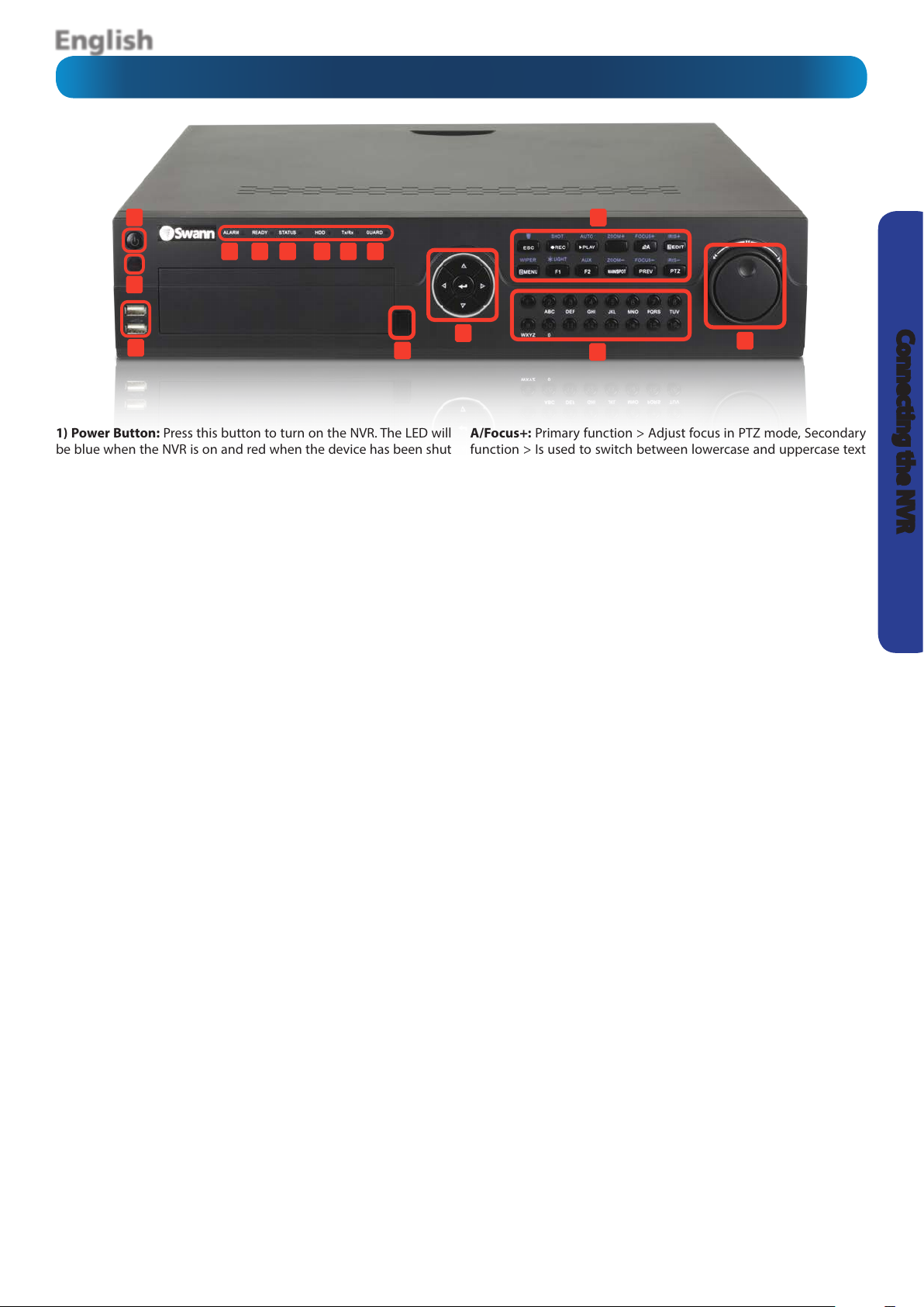
Front Panel of the NVR
Connecting the NVR
1) Power Button: Press this button to turn on the NVR. The LED will
be blue when the NVR is on and red when the device has been shut
down.
2) Infrared Sensor: Monitors signals coming from the infra-red
remote control. If this sensor is blocked or obstructed, then the
functionality of the remote will be impaired.
3) USB 2.0 Ports: For connecting USB external storage for backup, or
for applying new rmware.
4) Alarm LED: Will be lit when a sensor alarm is detected.
5) Ready LED: Indicates that the NVR is ready and functioning
correctly.
6) Status LED: This will be lit if you are using the supplied remote
control and the device ID is set to 254. It will not be lit if the device
ID is set to 255 (default setting). The LED will turn red when using a
RS485 keyboard.
7) HDD LED: Will ash whenever the NVR is writing to/reading from
the installed hard drive.
8) Tx/Rx (LAN) LED: Flashes rapidly when the NVR’s network port is
sending or receiving information.
9) Guard LED: Will be lit when the NVR has been armed. The LED will
turn o when the NVR is unarmed. The arm/disarmed status can be
changed by pressing and holding the ESC button for more than three
seconds in live view mode.
10) DVD Eject Button: If you have a DVD-ROM/Writer installed, this
button will open/close the DVD tray.
11) D-Pad: For navigating around menus when you are not using
the mouse. The enter button is used to conrm your selection. It is
also used to tick checkbox elds and to play/pause video in Playback
mode.
12) These buttons have multiple functions depending on which
mode you are currently in. The text and symbols in blue are the
secondary function:
ESC/Guard: Primary function > Go back to the previous menu,
Secondary function > Press this to arm/disarm the NVR. Press and
hold for more than three seconds in live view mode to arm or disarm.
REC/Shot: Primary function > Enters the Manual: Record menu,
Secondary function > In PTZ mode, you can recall a preset by pressing
this and then one of the alphanumeric numbers. It is also used to turn
the audio on/o in Playback mode.
Play/Auto: Primary function > Enters Playback mode, Secondary
function > Is used to auto scan in PTZ mode.
Zoom+: Is used to increase zoom for a PTZ camera in PTZ mode.
A/Focus+: Primary function > Adjust focus in PTZ mode, Secondary
function > Is used to switch between lowercase and uppercase text
input and for symbols and numeric input.
Edit/Iris+: Primary function > Allows you to edit text elds. It will
also function as a backspace button to delete characters in front of
the cursor, Secondary function > Adjusts the iris of the camera in PTZ
mode.
Menu/Wiper: Primary function > Allows you to enter the main menu,
Secondary function > Enables the camera wiper in PTZ mode. In
Playback mode, it is used to show/hide the control toolbar.
F1/Light: Primary function > Is used to select all items on a list when
used in a list eld, Secondary function > In PTZ mode, it is used to
turn on/o the PTZ light (if applicable). In Playback mode, it is used
to switch between play and reverse play.
F2/Aux: Primary function > Cycles through the various tabs in the
main menu, Secondary function > In synchronous Playback mode, it
is used to switch channels.
Main/Spot/Zoom-: Primary function > Switch between main and
spot output, Secondary function > Is used to decrease zoom for a
PTZ camera in PTZ mode.
Prev/Focus-: Primary function > Switch between single view and
multi view mode, Secondary function > Adjust focus in PTZ mode in
conjunction with the A/Focus+ button.
PTZ/Iris-: Allows you to enter the PTZ menu, Secondary function >
Adjusts the iris of the camera in PTZ mode.
13) Alphanumeric Buttons: These buttons will allow you to switch
to the corresponding channel in live view and Playback modes.
The buttons will have a dierent LED status depending on what is
happening:
Blue > The camera is currently recording. The button will not be lit
when the camera is not recording.
Red > When streaming a live image across the network. The camera
is currently not recording.
Pink > When streaming a live image across the network while the
camera is recording.
14) Jog Shuttle Control: In Playback mode, the outer control is used
to speed up or slow down playback and can be used as left/right
control when navigating menus. In live view mode, it can be used
to cycle through the available channels. The inner control is used to
jump ahead or behind 30 seconds in Playback mode and can be used
as up/down control when navigating menus. In PTZ mode, it can be
used to control the movement of a PTZ camera.
5
Page 6
English
1
2
3
4
5
6
7
8910
11
12
Connecting the NVR
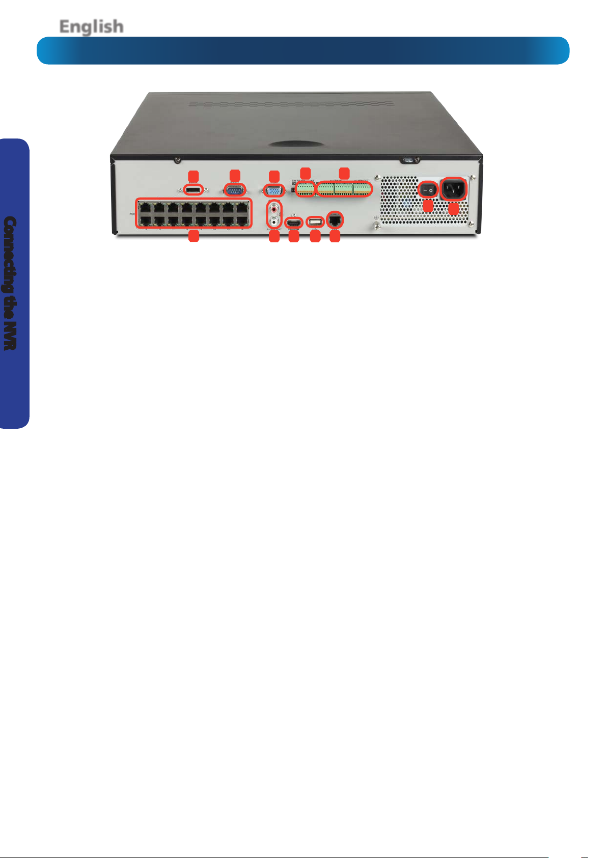
Rear Panel of the NVR
1) Video Inputs 1 - 16: These are your primary video inputs.
The channels are labelled by number in the same order as they
will appear on your NVR’s interface. Each accepts an Ethernet
(RJ45) plug, which is the same type plug as the Network Port.
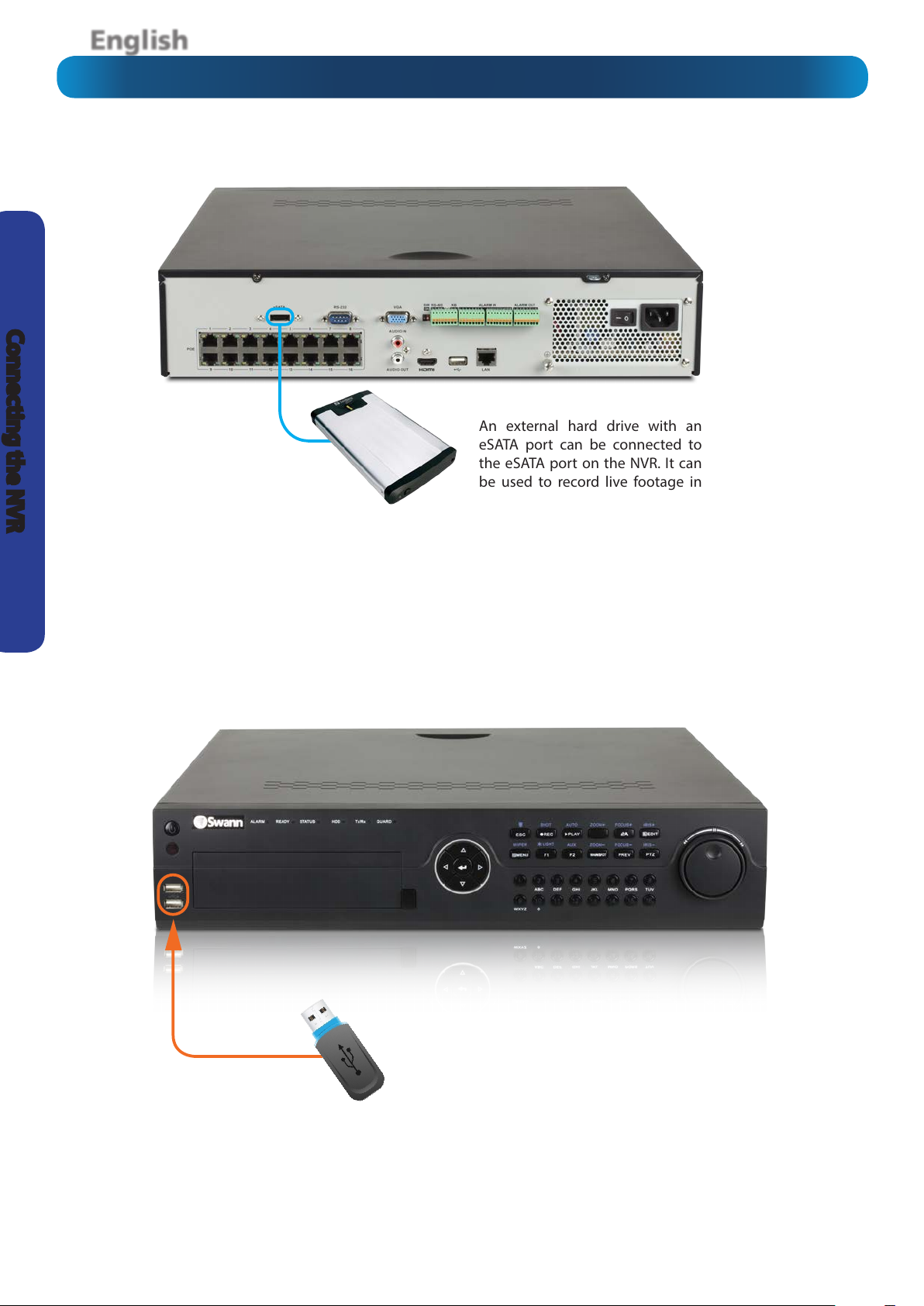
2) eSATA Port: An external hard drive with an eSATA port can
be connected to the eSATA port on the NVR. It can be used
to record live footage in the same way as the internal hard
drives(s).
3) RS-232 Port: To connect the NVR to the serial port on your
computer. It is mainly used for low level testing and is not
required for day to day use.
4) VGA Output: For connecting a television or PC monitor
with a VGA input.
5) Audio Input/Output: As the cameras supplied with the
NVR do not support audio capture, the Audio Input/Output is
not required for normal operation.
6) HDMI Output: The primary output of the NVR. For the
highest possible video output quality, we suggest using this
output.
7) RS485 Port: Connector for RS485 devices.
8) USB 2.0 Port: The supplied mouse connects here. You can
also connect USB external storage devices for backup or for
applying new rmware.
9) Alarm & Sensor I/O Block: For connecting external alarm
sensors and/or alarm output devices (such as sirens or lighting)
to the NVR.
10) Network Port: Where you can connect the NVR to a
network, typically directly into the router or network switch.
11) Power Switch: Master ON/OFF switch.
12) Power Input: Where you connect the included power
cable.
6
Page 7
English
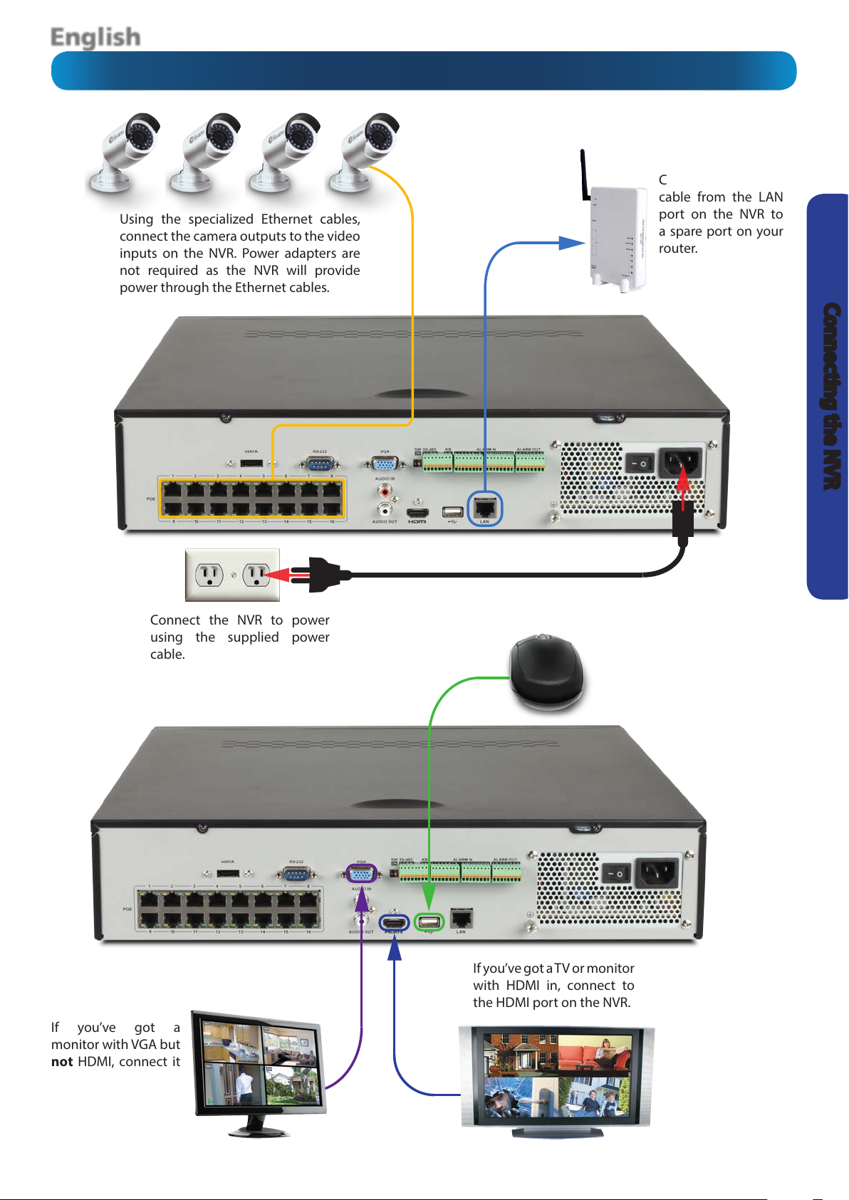
Using the specialized Ethernet cables,
connect the camera outputs to the video
inputs on the NVR. Power adapters are
not required as the NVR will provide
power through the Ethernet cables.
Connection Diagram
Connect an Ethernet
cable from the LAN
port on the NVR to
a spare port on your
router.
Connecting the NVR
Connect the NVR to power
using the supplied power
cable.
If you’ve got a
monitor with VGA but
not HDMI, connect it
to the VGA output on
the NVR.
Connect the mouse to
the USB 2.0 Port.
If you’ve got a TV or monitor
with HDMI in, connect to
the HDMI port on the NVR.
7
Page 8
English
Connecting the NVR
Connecting Additional Devices
An external hard drive with an
eSATA port can be connected to
the eSATA port on the NVR. It can
be used to record live footage in
the same way as the internal hard
drives(s).
The front USB 2.0 port can be
used for backing up footage to a
USB Flash Drive or USB Hard Drive
(HDD).
8
Page 9
English
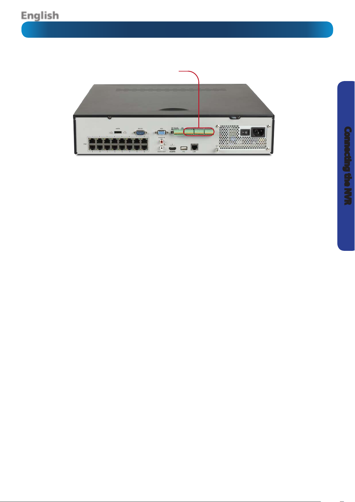
Alarm & Sensor I/O Block
The NVR has 16 alarm
inputs and 4 alarm outputs, for connecting external sensors.
Connecting the NVR
Alarm In 1 - 16: Connect the output from external sensors
here. Only one of the two should be connected here, the
other should be connected to the Ground terminal (consult
the documentation for the sensor).
The Alarm In number does not directly correspond with a
channel number - these can be set later (page 44).
Alarm Out 1 - 4: The outputs for connecting an external alarm
device, such as a siren or security lights, to the NVR.
Please note, the alarm & sensor I/O block does not provide
power to alarms and sensors. Please make sure that a power
supply was included with your device.
9
Page 10
English
Basic NVR Operation
Basic Setup
Starting the NVR for the rst time:
When you rst boot the NVR, it will automatically start the
Setup Wizard which will guide you through the various
setup options available.
The USB Mouse (Recommended)
The easiest way to operate the NVR is to use the included USB
optical mouse - we put together the look and feel of the menu
system specically for mouse-friendly navigation.
The controls are pretty easy to remember - heck, there are only
two buttons. It couldn’t be simpler.
Left click:
• Selects an item or conrms a choice.
Right click:
• Opens the menu bar from the live viewing screen.
• Returns one “step” from a submenu.
• Opens a context menu in some settings screens.
The Scroll Wheel:
• Can be used to adjust the values of sliders and scales
when highlighted by the mouse.
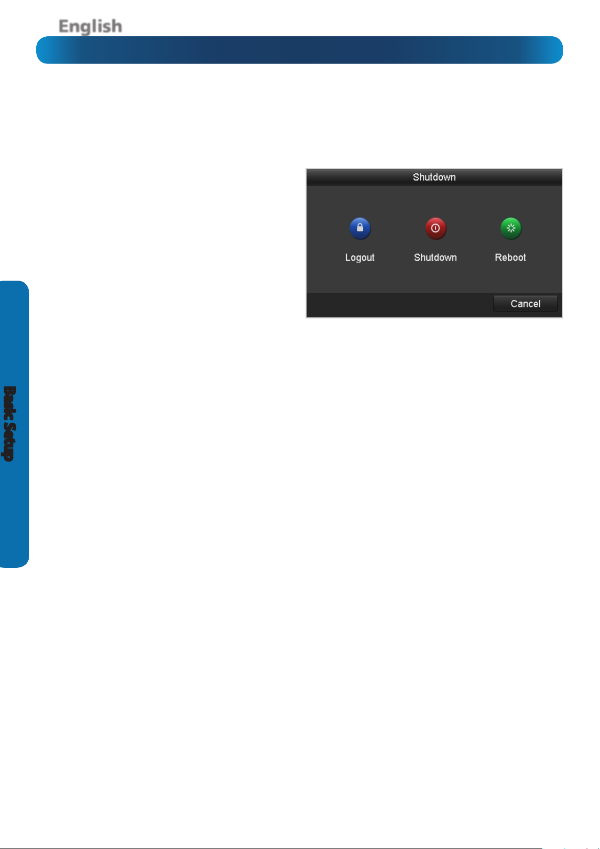
Shutting Down & Rebooting
If you want to shut down or reboot the NVR, or simply log out
of the user account you’re logged in as, access the Shutdown
menu, accessible via the main menu.
To ensure the integrity of your data and recordings, always
select Shut Down when powering o the NVR.
Note: Wireless Mice and Bluetooth devices
Note that Wireless Mice and Bluetooth devices are NOT
compatible with the NVR. Please use the USB optical mouse
supplied.
10
Page 11
English
The Setup Wizard
The wizard contains six quick setup screens which
will allow you to choose how you want the NVR to
behave. Please be patient as it can take up to 60
seconds for the wizard to appear after the NVR is
turned on.
You’ll be asked to:
• Select a language.
• Set a password for the ADMIN account.
• Congure the time, date and time zone for your
location.
• Congure the NVR so it can operate on your
network and access (and be accessed from) the
Internet.
• Initialize and format your hard drive(s), if required.
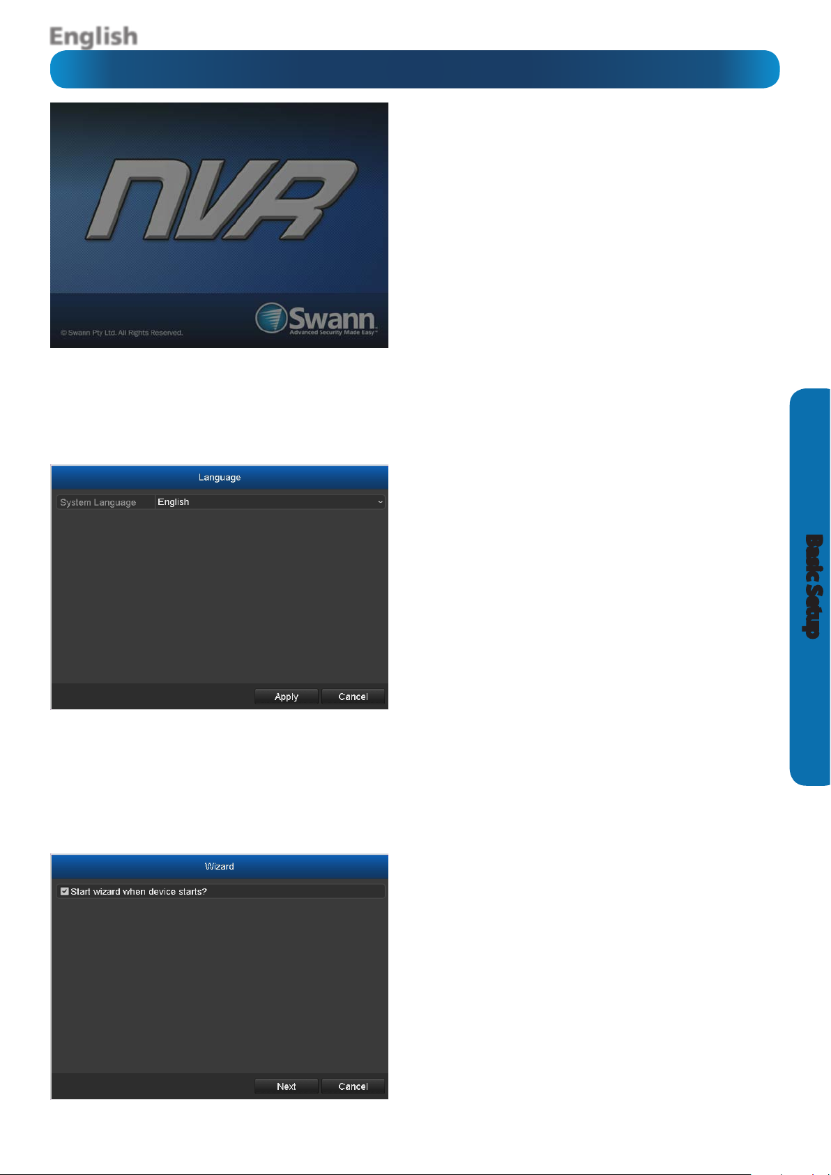
Setup Wizard: Language
System Language: Choose the language you’d like
the menu system to be displayed in.
Setup Wizard: Wizard
Basic Setup
When this check-box is left ticked, the setup wizard
will run again the next time the NVR is rebooted or
powered on. If you don’t want the wizard to start next
time the NVR is turned on, uncheck this box.
To access the wizard once it’s been disabled, open
Main Menu > Conguration > General and select
Enable Wizard.
11
Page 12
English
The Setup Wizard
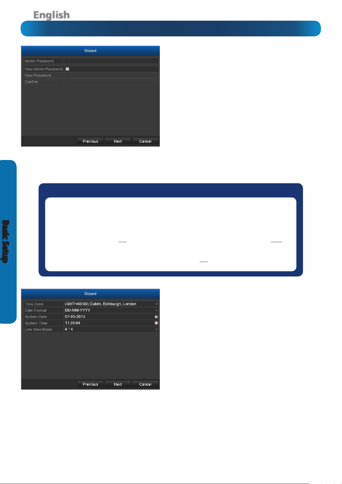
Setup Wizard: Admin Password
For your on-going security and peace of mind, we
strongly suggest setting a password for your Admin
account. A password can be any combination of numbers (no letters) up to 16 numerals long.
Admin Password: Enter the existing Admin password
here. The default password for the Admin account is
12345. Don’t enter what you’d like the password to be
- that goes in the elds below this one.
New Admin Password (check-box): When checked,
the NVR will accept a new password for the Admin
account.
New Password / Conrm: Enter what you’d like the
new password to be in the upper eld, and then conrm it in the lower eld.
Basic Setup
Default Password Information
To ensure your privacy, this NVR supports password protection.
The default, all-access username is “admin”, the default password is “12345”.
To ensure your on-going privacy, we strongly recommend setting a password as soon as possible.
Choose something that you’ll remember, but that others would be unlikely to guess.
IMPORTANT NOTICE - Do not lose or forget your password. To ensure that your NVR has the best
security possible, password recovery has been designed to be a complicated and time consuming
process. Only a select number of sta at the Swann Technical Support Telephone Helpdesk can assist.
Password retrieval can take several days, which means you will not be able to access your NVR during
this time.
Wizard: Time, Date, Location, Live View
It’s important to ensure that your NVR has the correct
time and date, as well as the correct time zone set.
This is particularly true in a legal context when a mistaken time or date can mean the dierence between
your security footage being regarded as legitimate
evidence or not!
Time Zone: Select your location from the list. The East
Coast of the United States is GMT -05:00 and the West
Coast is GMT -08:00. The UK is at GMT+ 00:00 and the
East Coast of Australia is at GMT +10:00.
12
Remember that these values will be displaced by an
hour during DST (daylight savings time) if that applies
in your locale. However, don’t set that here - the NVR
supports automatically adjusting the time during DST
- see page 35.
Page 13
English
The Setup Wizard
Wizard: Time, Date, Location, Live View (ctd)
Date Format: How you’d like the date to be displayed. For best results, use the standard format for your
location (MM-DD-YYYY for the USA, DD-MM-YYYY for the UK and Australia).
System Date: The current date setting on the NVR. To alter this value, select the small calendar icon.
System Time: The current time setting on the NVR. To alter this value, select the small clock icon.
Note for NTP Users: Setting the date and time is less important if you’re using NTP (Network Time Proto-
col) but we still recommend you set it here, rst. Just in case.
Live View Mode: 4 x 4 is the default mode for live video mode. This will display up to 16 video channels
on-screen at a single time. Selecting 1 x 1 will display the rst video channel full-screen - see page 45.
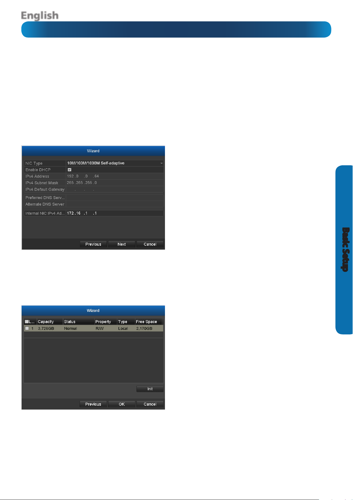
Wizard: Network Settings
NIC Type: What sort of network you’re using. There
are a few to choose from. The vast majority of users will use the default option of 10M/100M/1000M
Self-adaptive. If you’re using a network other than this
type, chances are you know about that.
Enable DHCP (check-box): Ensure that this is
checked unless you’re specically running a manually
addressed network (sometimes called static IP addressing) or your router doesn’t support DHCP.
IPv4 Address, Subnet Mask, Default Gateway:
When you’re using DHCP, these values will self-populate. If you’re using a manually addressed network,
you’ll need to set these to match the other devices on
your network.
To learn more about the Network settings of the NVR see page 37.
Wizard: HDD Management
Here, you can view and initialize the hard drive(s) in
the NVR. Typically, there will be only one entry here,
the HDD which came with the NVR (if one was included). Each drive will be identied and be listed along
with statistics such as Capacity, Status and Free Space.
If you’re booting the NVR for the rst time, the HDD
should already be initialized or if you’ve just installed
a new HDD, then you’ll need to initialize the drive.
Basic Setup
Init: Initializes the HDD so that it’s ready to accept
data.
Warning: Don’t initialize a drive that already has data
on it, as the initialization process will erase any information on the drive.
13
Page 14
English
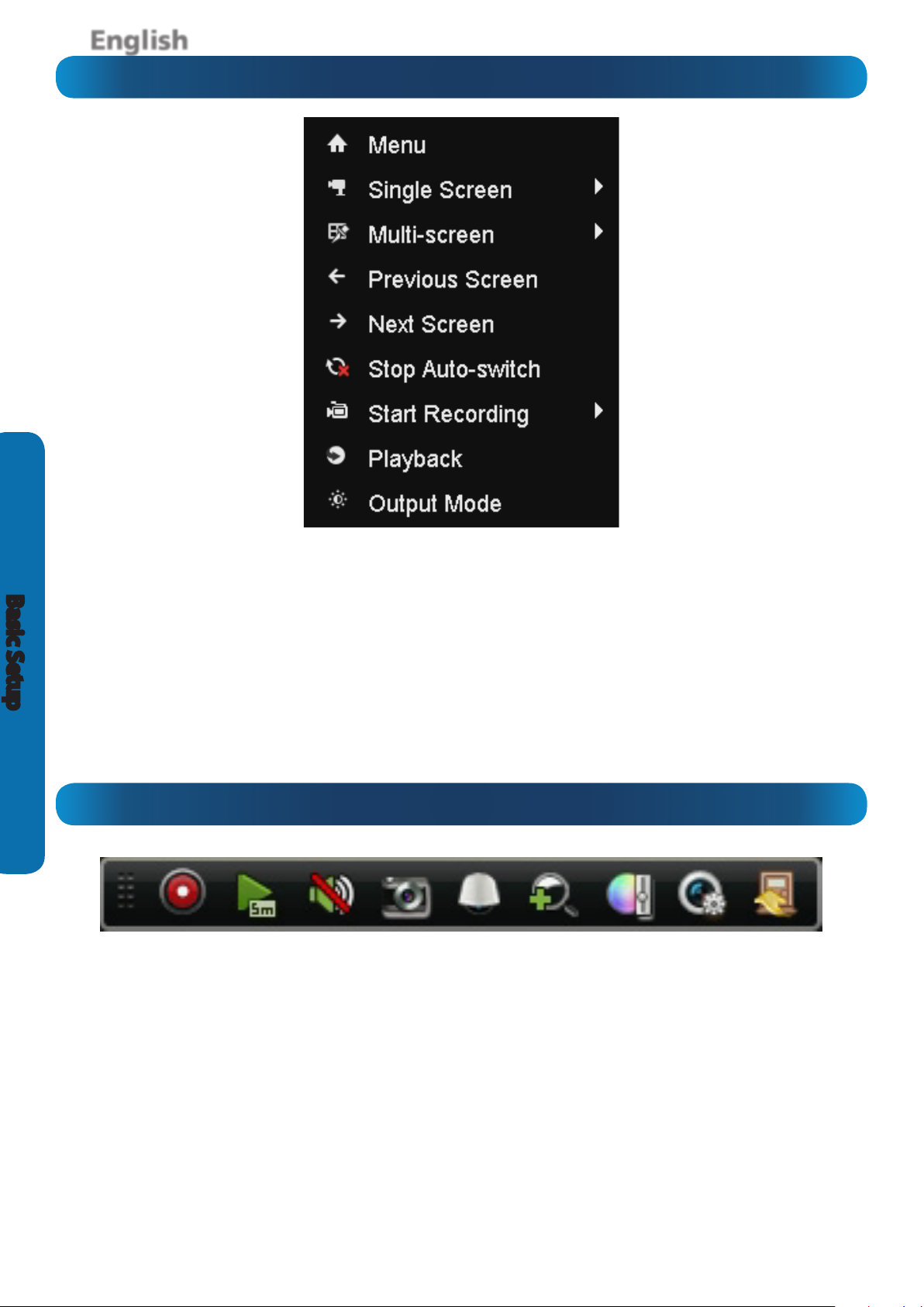
The Quick Menu
Basic Setup
To access the Quick Menu, right click the USB mouse once.
Menu: Opens the Main Menu (see page 16).
Single Screen: Opens a single channel for viewing in full-
screen mode. The slide-out menu contains a list of channels
to choose from.
Multi-Screen: Select a multi-screen viewing option, where
you’ll be able to see multiple video feeds at once.
Previous Screen: Moves to the previous channel.
Next Screen: Moves to the next channel.
The Quick Camera Menu
To access the Quick Camera Menu, left click the USB mouse
once on one of the live video inputs available.
Recording: Start or stop live recording.
Instant Playback: Playback the last 5 minutes of recorded
video.
Audio On: As the cameras supplied with the NVR do not
support audio capture, the Audio On option is disabled.
Capture: Allows you take a snapshot which is saved in JPEG
format.
Start Auto-switch: Will periodically display a dierent video
feed from each channel available.
Start Recording: Begins recording on all channels
immediately, regardless of the current recording schedule.
Playback: Allows you to playback recordings from a single
channel for the current day. Move the cursor over one of the
live video inputs that you would like to playback, right click
the USB mouse, then select Playback.
Output Mode: Allows you to change the contrast level of the
video display.
button on the USB mouse to zoom, and press the right click
button to exit. Use the PIP (Picture-in-Picture) screen on the
bottom right to select a dierent area to zoom to.
Image Settings: Change the brightness, contrast, saturation
and hue of the live video feed.
Live View Strategy: Allows you to change how you view the
live video feed. You can select a higher quality video feed with
a lower frame rate or you can decrease the quality and have a
higher frame rate. Please note, this does not aect the quality
of recorded video.
PTZ: To control a PTZ camera if you have one connected to
the NVR.
Digital Zoom: Enter Digital Zoom mode. Press the left click
14
Close: Close the menu.
Hovering the mouse cursor over each button or icon will
display a description of what it does.
Page 15

English
Operating the NVR Locally
If you’re reading this page, it means that either:
• You’ve got the NVR setup, but its standard recording
program isn’t for you. Fair enough - we cater to all
requirements here.
• You’re interested in what other options and
capabilities the NVR has. Excellent - the answer is “a lot”.
• Everything works except just that one thing that isn’t
right but you don’t know where the option is. Darn.
We’ll try and get you xed up by the end of this page.
There are some sections of Advanced Conguration that we
think are of benet for most NVR owners to know about - in
particular, the Alarm settings and the Email Conguration of
the NVR.
By Default...
• The NVR has motion recording enabled on every channel,
congured to operate at an average level of sensitivity.
• To be a little more likely to record a border-line motion
event than not (we think it’s better to get a false trigger
than miss an event).
• To record video each time it detects a motion event, but
not notify you via email (all events will be listed in the log).
Quick Reference
Some of the more common reasons to have a look in the
Advanced Conguration include:
Altering the Recording Schedule
The recording schedule is one of the most important things to
get right when conguring the NVR. More information about
the schedule can be found at:
• “Record: Schedule” on page 21
Conguring the Auto-Email Functions
If you want the NVR to notify you via email when it detects a
motion event, then you’ll need to congure:
• “Conguration: Network: Email” on page 40
• “Camera Management: Motion” on page 28
Altering the Motion Detection Settings
If you want to change the way the NVR handles motion, then
you’ll need to look at:
• “Camera Management: Motion” on page 28
Basic Setup
To alter the NVR’s default behaviour, you’ll need to change
some of the advanced settings.
You can do this on the NVR directly or by using the SwannView
Plus client software located on the included CD, there is a fairly
comprehensive manual also included. You can also access the
NVR’s built-in web interface using your Internet browser.
• “Camera Management: Image” on page 27
Connecting External Sensors to the NVR
To congure external sensors, pair them to video channels
and change the associated action for each, see:
• “The Alarm & Sensor I/O Block” on page 9
• “Conguration: Alarm: Input / Output” on page 44
15
Page 16
English
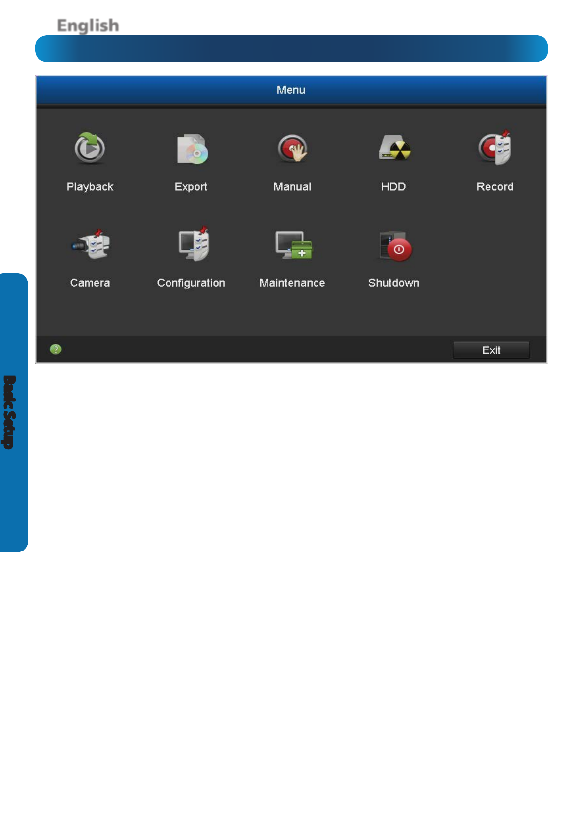
Menu Layout
Basic Setup
Playback: To access recorded images, use the Playback menu.
There are several playback modes to choose from, such as
standard chronological playback mode, or event playback
mode.
Export: To copy or backup footage from the NVR, use the
Export menu. You’ll need a compatible USB Flash Drive or USB
Hard Drive (HDD) to store the data.
Manual: Access manual controls for the recording and alarm
functions of the NVR.
HDD: Where you’ll be able to access information about and
adjust the settings of your hard drive(s).
Record: Access recording options, such as quality, resolution,
bitrate and the recording schedule.
Camera: Adjusts and congures how the NVR looks for
cameras via the video inputs. Access to Motion Detection
conguration is located here.
Conguration: Access and congure many settings of the
NVR, including your network settings, adjusting the time and
date, creating or altering user accounts and adjusting the
behaviour of the alarm inputs/outputs.
Maintenance: For changing how the NVR performs its
automatic maintenance and for upgrading the NVR’s rmware.
Shut Down: To safely lock, shut down or reboot the NVR.
Hovering the mouse cursor over each button or icon will
display a description of what it does.
16
Page 17
English
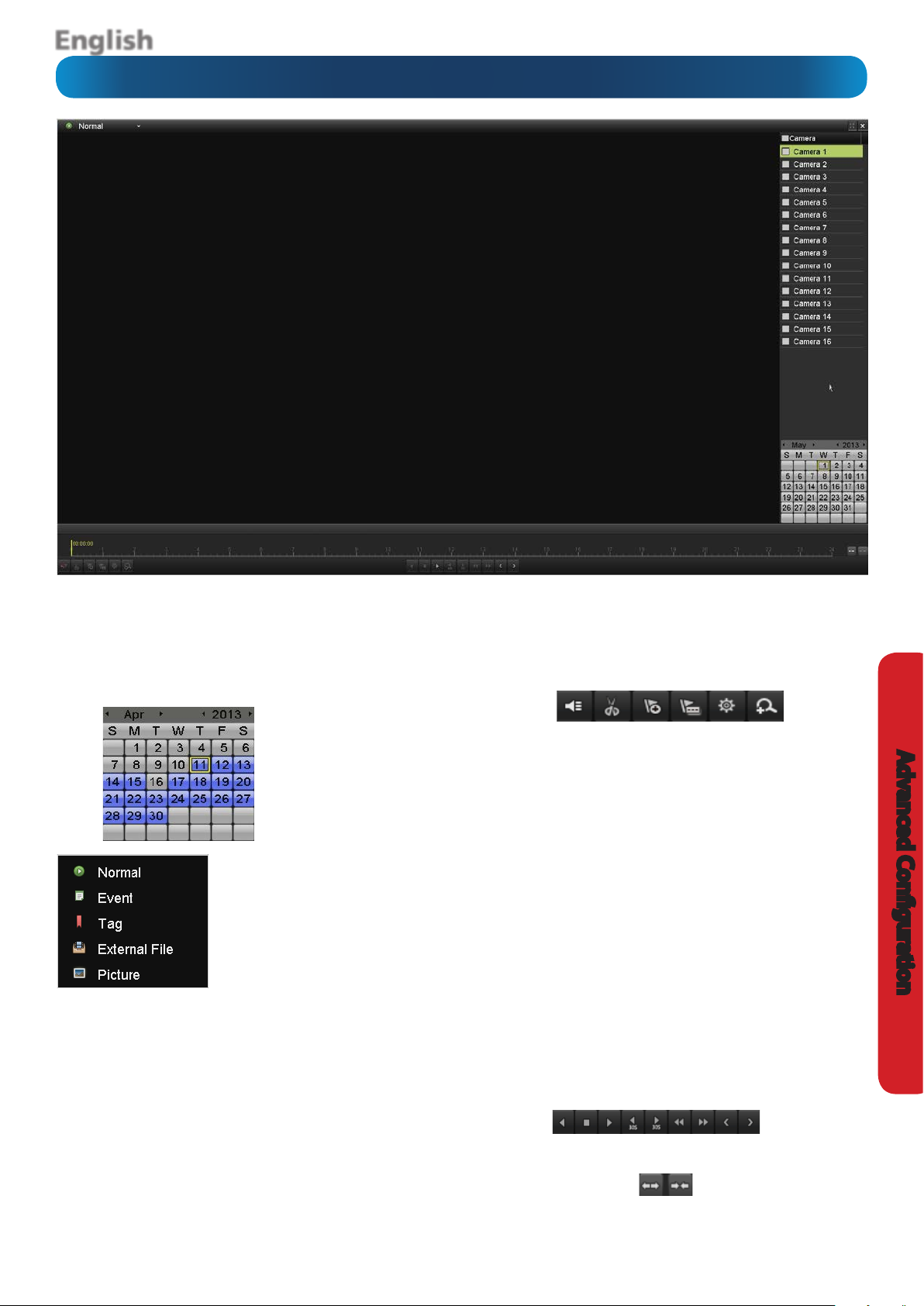
Playback
Camera: Select the camera that you’d like to playback. Up to sixteen
cameras can be selected.
For Normal event playback, you will see a calender display underneath
the camera selection. When you have selected one or more cameras,
you will see the dates highlighted in blue that contain video footage
from those cameras:
You can select a particular
date, month and year. The
dates highlighted in blue
contain video footage
from one or more cameras
connected.
You can also select the type of event
that you would like to playback. The
options are Normal, Event (Alarm Input,
Motion), Tag, External File and Picture.
When you select Alarm Input, you can
select up to sixteen alarm inputs to
playback from.
Normal: Press the play button to play video. If you have selected
multiple cameras, double click a camera to view it full screen. Double
click again to exit full screen display. Blue sections on the timeline
indicate an alarm or motion event.
Event (Alarm Input, Motion): Select your start date and time and end
date and time, then press the Search button. A list of events will be
displayed on the right hand side. To initiate playback, select the Play
button on each event. Press the Back button to select a dierent time
period.
Tag: Gives you the option of searching for a particular tag. Tagging
allows you to record information such as location or people at a certain
point within the video. You can add tags in Normal and Event playback.
External File: Allows you to play video les from an external source
such as a USB Flash Drive or USB Hard Drive (HDD).
Picture: This NVR has the ability to enable a schedule if you want to
save a series of still pictures in JPEG format. This option allows you to
search for a particular still picture. See “Record: Schedule” on page
21 for details.
When playing your video, there are a number of options and controls
available:
Mute: Mutes audio playback.
Start clipping: This button allows you to set mark in and mark out points
on your video which you can then export to a USB Flash Drive or USB
Hard Drive. It’s a basic way to edit a video le that you have selected
to play. When you have selected to play a video le, press the Start
clipping button at the mark in point and press it again at the mark out
point. To save the le, press the Exit button. You will then be prompted
if you would like to save the le; click Yes to save. If you have made a
mistake, click the Exit button and click No. Repeat the above process.
Multiple mark in and mark out points can be applied.
Add default tag: Tagging allows you to record information such as
location or people at a certain point within the video. The default tag
name is TAG. Multiple tags can be added.
Add customized tag: Same as above but you can choose your own tag
name.
Tag management: This button allows you to edit or delete tags that you
have added to the video.
Zoom In: Enter Digital Zoom mode. Press the left click button on the
USB mouse to zoom, and press the right click button to exit. Use the PIP
(Picture-in-Picture) screen on the bottom right to select a dierent area
to zoom to.
Play controls: These are your play, pause, rewind and forward controls.
Zoom In/Zoom Out: Allows you to zoom in and out of the time line.
Zooming into the time line will allow you to have more precise control
for navigation.
17
Advanced Conguration
Page 18
English
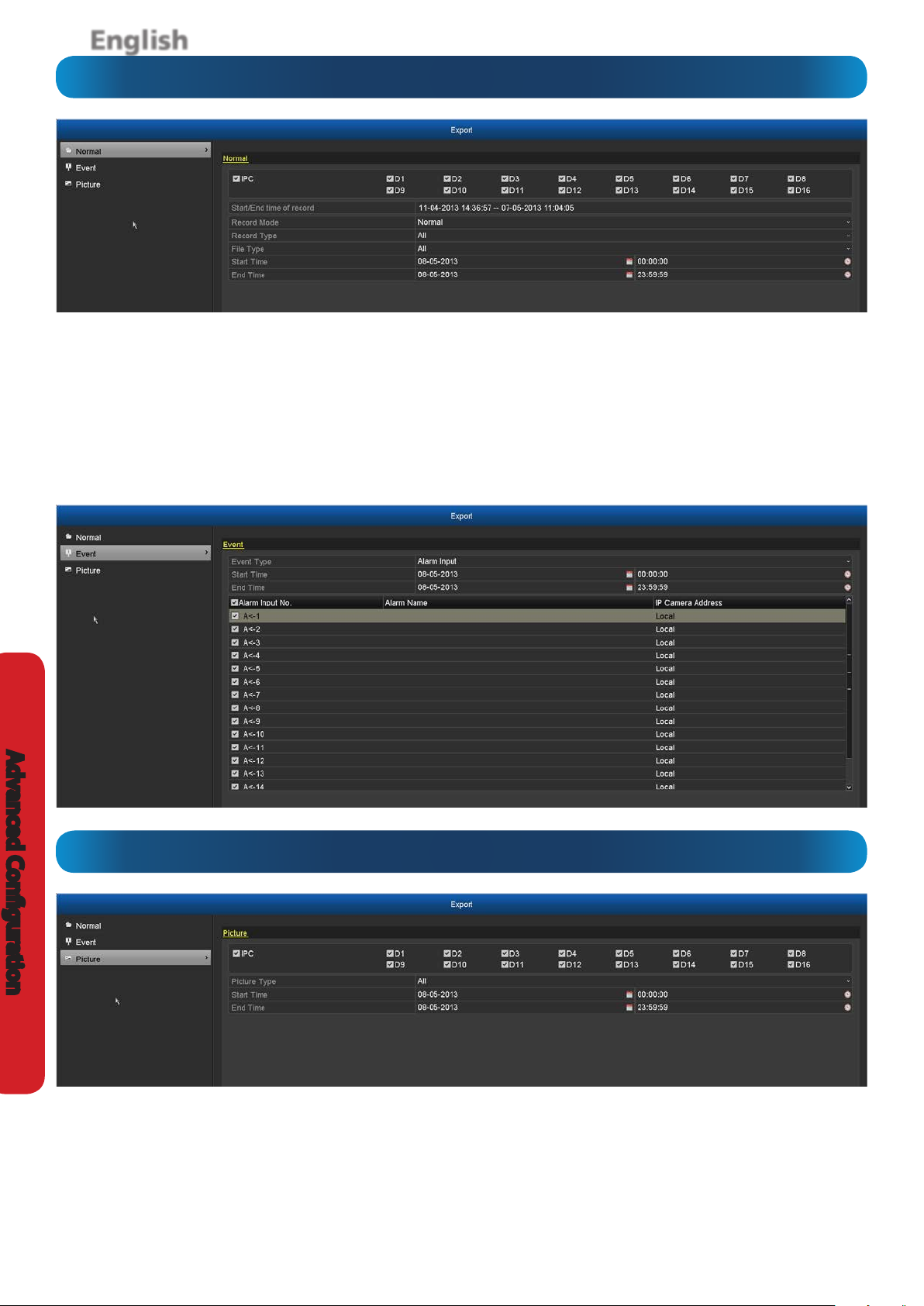
Export: Normal/Event
Advanced Conguration
The Export: Normal menu (above) will show you all
recordings that you can export to a USB Flash Drive or USB
Hard Drive (HDD).
From the Record Type menu, select the type(s) of video you’d
like to playback. The options are Normal, Motion, Alarm,
Motion | Alarm, Motion & Alarm, Command Triggered,
Manual and All. Set your Start Date/Time and your End
Date/Time and click the Search button.
The Export: Event menu (below) will show you recordings
that were triggered by the NVR detecting motion or by the
alarm sensor being triggered.
Export: Picture
The Export: Picture option allows you to export a series of
still pictures in JPEG format, that were triggered by the NVR
detecting motion or by the alarm sensor being triggered.
18
Page 19

English
Manual: Record
The Manual: Record menu allows you to override any default
recording schedules in place. The recording schedule for each
camera connected, can be changed. Pressing the button next
to IP Camera will stop recording on all cameras. You can also
control each camera by pressing the button next to each of the
camera names. You can select normal recording (Recording by
manual operation) or motion detection recording (Recording
by schedule).
Normal: The NVR will constantly record for any period where
Normal is selected. You won’t miss anything, but constant
Manual: Continuous Capture
recording will ll your hard drive very quickly. (The NVR does
record the equivalent of a DVD lm every two hours on every
channel, so that’s rather a lot of data!) Typically, we suggest
Motion Detection as a better recording mode for most users.
Motion Detection: The recommended recording setting for
most applications. The NVR will only record when it detects
something moving in front of a camera, and will then only
record footage from the camera(s) that do detect motion
unless you alter your Action settings “Camera Management:
Motion” on page 28 to include other channels.
Advanced Conguration
The Manual: Continuous Capture option is used to save a
series of still pictures instead of recording video.
Manual: Alarm
The Manual: Alarm menu allows you to send a trigger to the
alarm output(s) to see that it is working correctly.
19
Page 20

English
HDD: General
Advanced Conguration
The HDD: General menu allows you to initialize the hard
drive(s) in the NVR. Don’t initialize a drive that already has data
on it, as the initialization process will erase any information
on the drive. You also have the option of adding a Networkattached storage device (NAS) that you can record to.
Add: Create a folder on your NAS device, then input the IP
address of your NAS device and the folder name that you
created earlier.
HDD: Advanced
Init: Initializes the HDD so that it’s ready to accept data.
To nd out which NAS devices are compatible with our NVR,
please visit our website www.swann.com or contact Swann
Technical Support Telephone Helpdesk.
The HDD: Advanced menu allows you to congure a quota
on the HDD for each camera that is connected to the NVR.
Each camera can be allocated a certain amount of space that
is available on the HDD. If you have multiple HDDs installed,
you can also instruct the NVR on which HDD each camera can
record to.
20
To do this, for Mode select Group and click the Apply button,
you will then be asked to restart the NVR for this selection to
take eect. When the NVR has rebooted, go to HDD: General.
You will see an Edit option; click this to select a dierent
property and group for that particular hard drive installed.
Click the Advanced menu, for Record on HDD Group; you
can select a dierent group and which cameras are assigned
to that group.
Page 21

English
Record: Schedule
Important Guidelines
The schedule presented on-screen applies to one channel
only.
Use the Copy function to quickly assign identical schedule
layouts to multiple channels at once.
Be careful when programming your schedule. It’s one of the
most important aspects of setting up your NVR, and if it’s
wrong in any way, it could lead to disastrous complications
later.
Camera: Select a camera that you would like to add a schedule
to.
Enable Schedule: Select this to enable the schedule.
Copy (Channel): Located at the base of the screen, this will
allow you to copy the schedule from the channel you’re
editing to another channel or channels.
Note: The Action Options for Motion Detection and the
External Sensors will aect the way the schedule works.
By default, all channels are armed to use Motion
Detection as their recording mode, but not to use
external sensors (not included).
Recording Modes:
There are four types of recording to choose from.
Normal: The NVR will constantly record for any period where
Normal is selected. You won’t miss anything, but constant
recording will ll your hard drive very quickly. (The NVR does
record the equivalent of a DVD lm every two hours on every
channel, so that’s rather a lot of data!) Typically, we suggest
Motion Detection as a better recording mode for most users.
Motion: The recommended recording setting for most
applications. The NVR will only record when it detects
something moving in front of a camera, and will then only
record footage from the camera(s) that do detect motion.
It is recommended that Motion Detection is properly
congured for the channel(s) you want to associate with it.
See “Camera Management: Motion” on page 28 for more
information about setting up and conguring Motion
Detection.
Alarm: The NVR is armed to record if it detects an alarm
event. This is the setting you’ll want to use if you’ve connected
external sensors to the NVR’s alarm block.
Motion / Alarm (M / A): Will trigger the NVR to record on
either an alarm event or motion being detected.
Advanced Conguration
Motion & Alarm (M & A): Will trigger the NVR to record when
there is an alarm event and motion being detected.
None: As the name suggests, the NVR will not record
anything.
Capture: This option is used to save a series of still pictures
in JPEG format instead of recording video. By default, the
schedule has not been enabled for all channels for this option.
21
Page 22

English
Record: Encoding
Advanced Conguration
Encoding Parameters: Each video feed of the NVR is
comprised of two components, the Main Stream and the
SubStream.
Both the Main Stream and the SubStream are always active you don’t have to choose one for the NVR to use as it’s always
using both. You can, however, change the quality, size and
types of compression used for either.
Camera: Select a camera that you would like to alter.
Main Stream (Normal & Event): The images you’ll see in the
live-view interface of the NVR. This is the higher quality of the
two streams, and is what you’ll see on the NVR itself or via a
local network. When you alter settings for Normal, the same
settings will also apply to Event automatically.
Stream Type: What kind of data you want the stream to
contain. The cameras included with the NVR stream video
only.
Resolution: Select a resolution, up to the native resolution
of your camera. The higher the resolution, the more potential
detail there will be in your images. The higher your resolution,
the higher the bitrate will need to be to maintain a level of
detail per-pixel.
Frame Rate: The number of frames per second (fps) that the
NVR will record. The default (and maximum) is referred to as
“Full Frame” and is 30fps (NTSC) or 25fps (PAL).
Video Quality: The actual amount of data the NVR will use to
record video.
Pre-record: While Pre-record is enabled, the NVR will record
between X and Y seconds before an event occurs. It’s a little
like making the NVR psychic (but not really - it’s actually
just caching a few seconds of video which it adds to event
recordings as they occur).
22
If you’re using Motion Detection (recommended) and/or
Alarm based recording as your primary recording method(s),
then it’s a really good idea to use Pre-record - sometimes, if an
event is fast enough, it might have left view before the NVR
can trigger a recording. With Pre-record, there’s almost no
chance you’ll miss it.
Post-record: How long after an event occurs that the NVR
will continue to record. It can be very useful - for example, if
an intruder or potential target triggers the motion detection
but pauses in view; having Post-record enabled will get a
much better look at them. 30 seconds is the recommended
length for the Post-record setting, but it can be set higher (the
options are 5 seconds, 10 seconds, 30 seconds, 60 seconds,
120 seconds, 300 seconds, 600 seconds) depending on your
unique circumstances.
Expired Time (day): Determines how long the video footage
will remain on the hard drive without it being overwritten.
Record Audio (check-box): Whether the NVR will record
audio from this camera. The camera must contain a compatible
audio device for this option to be selectable. As the cameras
included with the NVR stream video only, this option is not
selectable.
Substream: A fraction of the Main Stream, and what you’ll
see over the Internet or via a mobile device. Typically, the
Substream will be of signicantly lower quality and bitrate
than the main stream.
Capture: Select a resolution, quality type and interval for
pictures to be saved in JPEG format.
Page 23

English
Record: Advanced
Overwrite: When enabled, the NVR will record over the les
already stored on the hard drive. The NVR will always record
over the oldest les on your hard drive rst.
Using the overwrite option is advisable, as the NVR will always
be able to record events as they happen. However, it does
mean that you’ll need to get important events o the HDD
before they’re overwritten.
Advanced Conguration
23
Page 24

English
Record: Holiday
Advanced Conguration
There are times when you won’t want the NVR to record using
its normal programming. Perhaps you require it to record
more, or less, or just at dierent times.
The Record: Holiday screen allows you to dene periods of
time where the NVR will employ an alternate recording mode
(perhaps at a dierent quality and on a dierent schedule as
well).
You can dene up to 32 holiday periods. These periods can be
delineated by date, by weeks or by the month.
Holiday Name: Choose a title for the holiday period in
question.
Enable: Whether the selected holiday period is enabled or
not.
Mode: Select mode by date, week or month.
Start Date: Select a start date.
End Date: Select an end date.
24
Page 25

English
Camera Management: IP Camera
The Camera Management: IP Camera screen is where you
can congure how and where the NVR will look for cameras,
and what networking protocols and settings you want to use
for them.
We are unable to provide direct support for cameras other
than those that came with the NVR.
Note: Depending on the type of camera(s) connected and their
method of connection, the NVR is able to self-populate many of
the elds on this screen. If you nd a value you can’t edit, this is
because the NVR automatically detects and sets the appropriate
value.
Protocol: Provides you with the option of changing the port
number for the Main Stream and SubStream video feed. We
recommend leaving the default settings as the NVR has been
congured to work with port 554 for RTSP (Real-Time Streaming Protocol).
Camera No: Displays the number of the currently selected
camera (see the list of cameras displayed below).
Edit: Provides you with the option of changing the network
settings of the camera. We recommend leaving the default
settings as the NVR will automatically detect each camera that
is connected.
Delete: As the NVR is designed to work with the network cameras provided, the delete function has been disabled.
Camera Name: Displays the name of the currently selected
camera.
IP Camera Address: The address of the camera currently selected.
Manage Port: The port number the selected camera is using
to communicate over the network to which it is attached.
Protocol: The way that the selected camera communicates
with the NVR. The cameras included with your NVR will be set
to SWANN.
Device Model: Displays the model number of the currently
selected camera.
Status: Displays the status of the currently selected camera.
Serial No.: Displays the serial number of the currently select-
ed camera.
Firmware: Displays the rmware version of the currently selected camera.
Note: You will see a window on the top left-hand side of the
screen with a Quick Add and Search buttons. As the NVR is
designed to work with the supplied cameras only, you cannot
add additional network cameras; therefore this feature has
been disabled.
Advanced Conguration
Live View: Press the play button to display a live view of the
camera that you have selected. A small preview screen will appear displaying a live view from the camera.
25
Page 26

English
Camera Management: OSD (On-screen Display)
Advanced Conguration
Camera Name: Select a name for the camera you’ve selected.
By default, all channels are named as the Camera No. eld, but
this can be set to anything you’d like up to 32 characters.
Display Name: Whether the name of the camera will be part
of the OSD information. This is entirely optional, and depends
on your preference.
Display Date: Whether the current date will be part of the
OSD information. We strongly recommend leaving this box
checked, and ensuring that the date is correct! For best results,
use NTP (see Conguration: Network: NTP - page 39).
Display Week: Whether the current day will be part of the OSD
information. We strongly recommend leaving this box checked,
and ensuring that the date is correct! For best results, use NTP (see
Conguration: Network: NTP - page 39).
Date Format: How you’d like the date to be displayed. We
strongly suggest setting this to the default standard for your
locale. For example: MM-DD-YYYY for the USA or DD-MMYYYY for the UK or Australia.
Time Format: Choose between 12-hour and 24-hour time.
Display Mode: How you would like the OSD to be displayed.
Bear in mind that some OSD settings (such as Transparent and/
or Flashing) are harder for a video forger to impersonate or
modify than other settings - on the other hand, they’re harder
to read. Select the best setting for your circumstances - it’s
worth having a look at a few settings to see what options are
available.
OSD Display Position: The inset OSD position window allows
you to set the exact positions of any overlaid text, such as the
camera name and the date and time.
Simply select any item you want to move (such as the Channel
Name and/or the Date and Time) and click and drag it to the
position you’d like it to be.
26
Page 27

English
Camera Management: Image
Mode: If you’re using only the cameras which came with the
NVR (recommended) or additional Swann cameras of the same
type, then the only option here will be Customize.
Future Swann IP Cameras may support additional image
adjustment modes, and if they do, they will be adjustable here.
Brightness: Changes how light the image appears to be.
However, it can’t make the camera see further in the dark, or
increase the clarity of an ill-lit image.
Contrast: Increases the dierence between the blackest black
and the whitest white in the image. Useful if sections of the
image “grey out” but setting the contrast too high will degrade
image quality.
Saturation: Alters how much color is displayed in the image. The
higher the saturation, the more bright and vivid colors will appear
to be. Again, setting this too high can degrade image quality.
Hue: Changes the color mix of the image (this can have
very dramatic results). It’s somewhat like moving through a
rainbow.
Remember: Your image settings will aect your recordings!
You can use the Image Settings to help ne-tune your Motion
Detection sensitivity. At night, the images that you see from
the camera may seem to icker slightly, or to have increased
“noise”. In video, “noise” is random uctuations of pixels, a little
like an old television that is not set to a station, often called
“static”.
By tweaking the Brightness and the Contrast you can eliminate
much of this video noise, increasing the quality of your images
and the accuracy of the Motion Detection.
Advanced Conguration
27
Page 28

English
Camera Management: Motion
Advanced Conguration
As Motion Detection is the default recording mode for the
NVR, it’s worth taking a moment to ensure it is properly
congured.
If the motion detection sensitivity is too sensitive, then the
NVR will record frequently or continually - any benet of
motion detection will be lost.
If the motion detection sensitivity is not sensitive enough,
then the NVR will not record when it should and may not
record anything at all.
We think that motion detection is the best way to get your
NVR to operate almost autonomously for long periods of
time (typically weeks to months) without you having to worry
about losing old footage.
However, it can be important that it’s congured correctly!
How Motion Detection Works
The way that the NVR looks for motion is quite straight forward
- it’s a process where it compares one frame (that is, a single
image taken approximately a 25th/30th of a second from the
previous image) with the next. A certain amount of “dierence”
between these two “frames” is interpreted as motion.
As a result, the NVR is able to detect when there is a change
in the picture. However, this does not necessarily need to be
something moving in the frame. For example, a light being
turned on or o, a lightning ash or even the sun coming out
momentarily on a cloudy day might be enough to trigger the
motion detection on the NVR. However, as these events last
only a moment (and are relatively rare) they will only create
a few very short redundant clips, which will not take up too
much space or pose a problem with scanning through footage.
Here, you’ll be able to set the motion detection features of
the NVR for each channel. We suggest that motion detection
is, under most circumstances, the most practical recording
method for the NVR to employ.
28
Page 29

English
Camera Management: Motion (ctd)
False Triggers
Setting the motion detection at high sensitivity levels increases
the frequency of false alarms. On the other hand, low sensitivity
levels increase the risk that a signicant motion event (such as
an intruder) will not trigger the motion detection to record.
Check the Motion Detection settings both during the day
and at night. In low-light conditions (or when your cameras
are using infrared night vision) the NVR may be more or less
sensitive to motion, depending on your unique circumstances.
The dierence might be very dramatic!
Weather
The weather conditions are going to aect your motion detection.
Dramatic weather phenomenon such as heavy rain, strong
winds, lightning and so on, may trigger the motion detection
with surprising frequency.
On the other hand, things like fog, mist and other obscuring
kinds of weather might mask or obscure something moving to
the point that the NVR fails to detect them.
• Limit the motion sensitive area to only the areas in view
that a target could be. In particular, large featureless
areas in the camera’s view are the ones most likely to
give false triggers - turning o the motion sensitivity
to any area a target cannot move in front of will help
reduce false triggers - see page 30.
Note: The motion detection feature will seem more sensitive
at night. We recommend that you test your motion detection
sensitivity both during the day and at night to ensure your
sensitivity setting is suitable for either lighting condition.
Some tips to customizing your motion detection
sensitivity and actions:
• Consider how important it is to be notied of motion
events as they happen.
Using the email alerts is a great way to be kept up-to-speed
on what’s happening, but may quickly become annoying if
something occurs which will generate a number of false triggers.
As a rule, we suggest employing the email alert only on interior
cameras during times that no one should be moving about in
front of them.
Which is the bigger problem - a dozen false triggers per day, or
missing one critical event?
There’s no magic setting which will make motion detection work
perfectly. There will always be some events that it’s not sensitive
enough to catch, or minor happenings that will trigger an overly
sensitive camera to record. Typically, the best motion detection
settings are one’s that give few false triggers but don’t miss
anything.
Even motion detection which false triggers a few times per hour
will still save a signicant amount of hard drive space compared
with a constant recording schedule for the same duration.
You can also use the Privacy Mask option to minimize false
triggers by obscuring dierent parts of your image - see page 31.
How it Works: Once motion detection has been enabled for
a channel, it will register to the NVR as a Motion Event. Thus,
you can use the Motion recording mode in the schedule to
trigger the NVR to record when motion detection triggers an
alarm signal.
Enable Motion Detection: Whether or not motion detection
is enabled on a specic channel. Each channel can be
congured independently of one another.
Say, for example, you are trying to monitor your front yard,
whilst in the background there is a busy street, and the cars
driving past continually set o the motion detection. What
can you do about it? Setting only part of the camera’s view
to be motion sensitive might be the answer. This is useful in a
number of circumstances, such as monitoring one particular
door at the end of a busy hallway, or a backyard with a tree
that keeps blowing in the wind.
Handling: Here you can dene what will happen when the
camera you’ve selected detects motion. You can trigger
additional cameras to start recording, you can adjust your
arming schedule, send alerts to the SwannView Plus software
or to email or trigger the alarm output.
Advanced Conguration
• It can be important to have a complete record of a
subject’s movements and actions for legal reasons.
If your cameras capture an illegal event (typically an intruder,
but we’re continually surprised by stories from our users) it is
important to have as much information as possible. For example,
images of someone in your home may not actually prove that
they broke in - but footage of them breaking a window does. If
you use a camera inside the home to trigger all exterior cameras
with pre-record enabled, then you will have a record of how they
entered in addition to what they did.
• Always consider what’s really important.
29
Page 30

English
Camera Management: Motion (ctd)
Advanced Conguration
To set the MOTION DETECTION AREA
In the MOTION DETECTION menu, select the AREA SETUP
(shown above) for the channel you wish to setup the MOTION
DETECTION AREA for.
• You will see a grid of red boxes. The outlined boxes mark
the area that is sensitive to motion. The area without
the red outlines is not sensitive to motion.
• Use the mouse to move the cursor around the screen.
• By left clicking an area in the grid, you can toggle motion
detection ON or OFF in that location.
• Click and drag to select the area you want to select or deselect.
In the sample image above, a person entering the room
through the window would trigger the motion detection.
However, a person entering from the right of screen should
avoid the motion sensitive area. This is a good solution to
monitor the windows (left of image) without getting false
triggers every time someone enters the room from the right.
Sensitivity: The Sensitivity setting is controlled by a slider,
allowing you to set a value between L (low) and H (high). The
closer to H the slider is set, the more sensitive the motion
detection will be.
Full Screen: Will select the entire area for motion detection.
Clear: Will clear the entire area.
Get an able-bodied volunteer to move about in front of
the cameras you’d like to tune the sensitivity for. The ideal
sensitivity level is when your volunteer moving about always
triggers the motion detection, but there are no false triggers
(or very few) when your volunteer isn’t moving about.
30
Page 31

English
Camera Management: Privacy Mask
A Privacy Mask can be used if you want to obscure part of
your image. You can also use this option to minimize false
triggers for motion detection. You can dene up to four areas
per channel to mask. Click and drag to select the area you
want to select or de-select.
Remember: Anything obscured by a privacy mask won’t be
shown in Live View and will not be recorded.
Advanced Conguration
31
Page 32

English
Camera Management: Tamper Proof
Advanced Conguration
Tamper Proong can be used in scenarios where someone
may cover up the camera’s eld of view or if they are attempting
to tamper with the video signal.
Camera: Select the channel that you want to enable for
tamper proong.
Enable Tamper-proof: Select this to enable.
Handling: Here you can dene what will happen when the
camera you’ve selected detects tampering. You can adjust
your arming schedule, send alerts to the SwannView Plus
software or to email or trigger the alarm output.
Sensitivity: Increase or decrease the level of sensitivity.
32
Page 33

English
Camera Management: Video Loss
Camera Management: Video Loss
Video Loss is regarded as a potential alarm event, and is
considered to occur any time that the NVR doesn’t receive an
active video signal on any of its inputs.
The default behaviour of the NVR, when a channel has no
incoming video signal, is simply to display “No Video” in white
text on a black background over the associated channel.
If you’re not using all the inputs on your NVR, then some
channels will be in “permanent” video loss state. Just be sure
that you don’t enable a video loss action for these channels.
Camera: Which channel/camera you’d like to set the video
loss behaviour for.
Enable Video Loss Alarm: Whether the selected channel has
video loss monitoring active or not.
Camera Management: Video Loss - Handling
Full Screen Monitoring: When the video signal has re-
established connection, the camera will display a full screen
image momentarily.
Audible Warning: The NVR will use its internal buzzer to emit
an alarm tone. It sounds like an old computer indicating an
error, or a large truck backing up.
Alert CMS Software: A warning message is sent to the
SwannView Plus client software installed on the computer.
Send Email: The NVR will send an auto-email alert when the
event type you’ve selected occurs. To congure your email
settings - see “Conguration: Network: Email” on page 40
for details.
Trigger Alarm Output: Instructs the NVR to output an alarm
signal from the alarm output terminal(s). The alarm output(s)
must be correctly connected and congured.
Advanced Conguration
33
Page 34

English
Conguration: General
Advanced Conguration
Language: The language that the NVR’s menus, alerts and
other communications will use. English is the only language
available.
Resolution: The number of “little dots” that make up an
image. This should be set as high as possible, but equal to
or lower than the maximum resolution your screen/monitor
can display. Things change a little depending on what kind of
monitor you’re using, and how it’s connected.
The NVR has ve formats available, in two dierent aspect
ratios:
Square (4:3) - 1024 x 768, 1280 x 1024 or 1600 x 1200
Widescreen (16:9) - 1280 x 720 (720p) or 1920 x 1080 (1080p)
Square Monitor via VGA: Use one of the 4:3 formats to
correctly align the NVR’s output on your screen. Using a
widescreen format will “stretch” the image vertically.
Widescreen Monitor via VGA: If possible, use the
widescreen (16:9) format. If your monitor can’t display that
resolution, you might need to enable letter-boxing on your
monitor and use a 4:3 format.
PC Monitor via HMDI: Choose a format appropriate for your
monitor. If it’s a widescreen, use a widescreen format. Set to
the highest option that is equal to or less than the screen’s
maximum resolution.
Widescreen Plasma/LCD HDTV via HDMI: The resolution
should be set to the maximum your television can process
not display. Typically, this will be 1080p, as even screens
which don’t have that many pixels can still display the image,
just with less detail. Check your television’s documentation
to learn this value. If your television can’t display 1080p, then
use 720p instead.
Time Zone: Particularly important if you’ve enabled NTP - set
this to the time zone where you happen to be. For example,
people in eastern Australia (Canberra, Sydney and Melbourne)
choose GMT+10:00, whilst the Eastern Time zone in the USA
and Canada is GMT-05:00. (GMT stands for Greenwich Mean
Time - it’s the baseline that keeps all the dierent time zones
in sync.)
Date Format: The format of the date (DD/MM/YYYY or MM
DD/YYYY and so on).
System Date: This can be edited manually, or set to update
automatically by using NTP (see “Conguration: Network:
DDNS/NTP” on page 39).
System Time: This can be edited manually, or set to update
automatically by using NTP (see “Conguration: Network:
DDNS/NTP” on page 39).
Mouse Pointer Speed: Move the slider to increase or decrease
the mouse pointer speed.
Enable Wizard: When checked, the NVR will automatically
run the setup wizard when the NVR is switched on. The wizard
itself contains the option to disable it.
Enable ID Authentication: When enabled, the NVR will
require a username and password to access, even for local
users.
34
Page 35

English
Conguration: General: DST Settings
Enable DST (check-box): Enable this setting if you’d like the
NVR to adjust the time when daylight savings time begins.
From / To: Here you can dene when daylight savings applies
to your location. There are many dierent standards for DST
which can vary dramatically even in the same time zone, so
you’ll need to tell the NVR when it applies to you.
DST Bias: This refers to the dierence in minutes, between
Coordinated Universal Time (UTC) and the local time. Select
the time that DST has increased by in your time zone.
NOTE: Some NTP servers are NOT fully compatible with DST
(Daylight Savings Time). This may cause your system to doublecount adding one or removing one more hour than they should,
or cancel each other out. You may need to intentionally change
your time zone to compensate, or simply not use NTP and DST
simultaneously.
Advanced Conguration
35
Page 36

English
Conguration: General: More Settings
Advanced Conguration
Device Name: The name that the NVR considers to be its own
and what it will use to register an IP address with your DHCP
host.
Device No.: The internal device number of the NVR.
Operation Timeout: Here you can change the time the NVR
will exit the menu screen and return to the camera viewing
screen if there is no activity.
Menu Output Mode: The menu output mode is currently set
to HDMI / VGA and cannot be changed.
36
Page 37

English
Conguration: Network
NIC Type: The NVR has the ability to connect to your LAN
(Local Area Network) at various speeds and can adjust
itself accordingly depending on the network trac. It is
recommended to leave the current default setting for the best
streaming performance.
Enable DHCP: DHCP (Dynamic Host Conguration Protocol) is
a system where one device on your network (usually a router)
will automatically assign IP addresses to devices connected
to the network. This option is enabled by default and is the
recommended way for the NVR to receive an IP address from
your router.
If you require the NVR to have a static IP address, you will need
to disable this option.
STATIC: Static networks require all devices to have their IP
addresses manually dened, as there is no device dedicated
to automatically assigning addresses.
IPv4 Address: Just as houses and businesses need to have an
address which identies their location on the road network,
so too do computers and other devices need addresses (called
IP ADDRESSES) to identify their position on the electronic
network. The NVR uses IPv4 addressing, which consists of four
groups of numbers between 0 and 255, separated by periods.
For example, a typical IP address might be “192.168.1.24” or
something similar. The most important thing when setting the
IP address is that nothing else on your network shares that IP
address.
IPv4 Subnet Mask: If the IP address is like a street address,
then a subnetwork is like your neighbourhood. This will be
formatted in a similar way to the IP address (i.e. four numbers
up to 255 separated by periods) but contain very dierent
numbers. In the above example, the Subnet Mask might be
something like: “255.255.255.0”.
IPv4 Default Gateway: This is the address of the “way to the
Internet” - to continue the road analogy, this is like your local
access point to the highway. This is an IP address in the same
format as the others, and is typically very similar to the IP
address of the NVR. To continue the above examples, it might
be something such as: “192.168.1.254”.
IPv6 Address 1/2/Default Gateway: IPv6 is the latest revision
of the Internet Protocol (IP). It will eventually replace the older
IPv4 system for assigning IP addresses to devices on your
network. The majority of internet server providers (ISPs) are
still using the IPv4 system but will eventually transition to IPv6.
As the NVR supports IPv6, you will be able to take advantage
of the new system when it arrives.
Mac Address: The Media Access Control address. This is
a unique code which nothing else should share. You can’t
change this one - it’s hard set when the NVR ships out.
MTU (Bytes): The MTU (Maximum Transmission Unit) is the
size of the largest datagram that can be sent over a network. It
is recommended to leave the default setting.
Preferred DNS Server: “Domain Name System”. Everything
on the Internet is located via an IP address - however, for
ease of use, we associate domain names (such as “www.
exampledomainname.com”) with those IP addresses. This
index is accessible in many locations online, and we call those
locations “DNS servers”.
Alternate DNS Server: A backup DNS server. This is here as a
redundancy - your NVR will probably work without one.
Advanced Conguration
37
Page 38

English
Conguration: Network: PPPOE
Advanced Conguration
PPPOE is an advanced protocol that allows the NVR to be
more directly connected via a DSL modem. This is an option
for advanced users only.
Username: Enter the username for your DSL account provider.
Password: Enter the password for your DSL account provider.
38
Page 39

English
Conguration: Network: DDNS/NTP
yourhostname.swanndvr.net
Your USERNAME
Your PASSWORD
Conrm PASSWORD
Static and Dynamic IP Addresses
In much the same way as your home network can use static
or dynamic IP addresses, many Internet providers don’t issue
(or charge more for) a static IP address for users. The easiest
way to nd out is to contact your Internet service provider.
Alternately, you can access the www.whatismyip.com service,
make a note of your IP, then reboot your router/gateway. This
should refresh your Internet connection. If your IP address
changes, you have a dynamic IP address. If it stays the same,
you may have a static IP - contact your ISP to conrm.
How do I deal with a dynamic IP address?
One option is to contact your ISP and request a static IP
address. They’ll usually charge a small fee for doing this. It’s
worth noting that not all ISPs oer static IP addresses.
If your ISP does not oer static IP addresses then you can use
a dynamic referencing service. We provide one free of charge.
We recommend using SwannDNS as your DNS service.
This is a free service for Swann DVR/NVR owners, which we
directly support.
To create an account with SwannDNS, go to:
http://www.swanndvr.net/
and click the Registration button.
Follow the prompts to create your account.
DDNS Type: SwannDNS is automatically selected as the DNS
service (www.swanndvr.net).
Device Domain Name: Enter the host name that you set up in
your DDNS service. This is the address you use to access your
network. For example: yourhostname.swanndvr.net
Username/Password/Conrm: Enter the username and
password you setup with your DDNS server. These do not have
to match your username/password combination in either your
NVR or router (for the sake of security, we suggest making
them dierent). Conrm your password in the eld provided.
For NVR users: Your username is the email address you
used to register the account. The password is whatever you
selected when you registered.
Advanced Conguration
NTP: Network Time Protocol. If you’ve got the NVR connected
to the Internet, you can have it automatically sync time with
an online server.
Important:
If you’re using NTP, then it is essential that your Time Zone
(see page 34) and DST (daylight savings time - see page 35)
be set correctly.
Interval (min): The amount of time in minutes that will
elapse between the NVR updating its internal clock to match
that of the NTP server. The default period of 60 minutes is
recommended.
NTP Server: The server you’d like to use for NTP. There are
many available online - the default (pool.ntp.org) works just
ne.
NTP Port: The port used by the NTP server of your choice. The
default for pool.ntp.org is 123.
39
Page 40
English
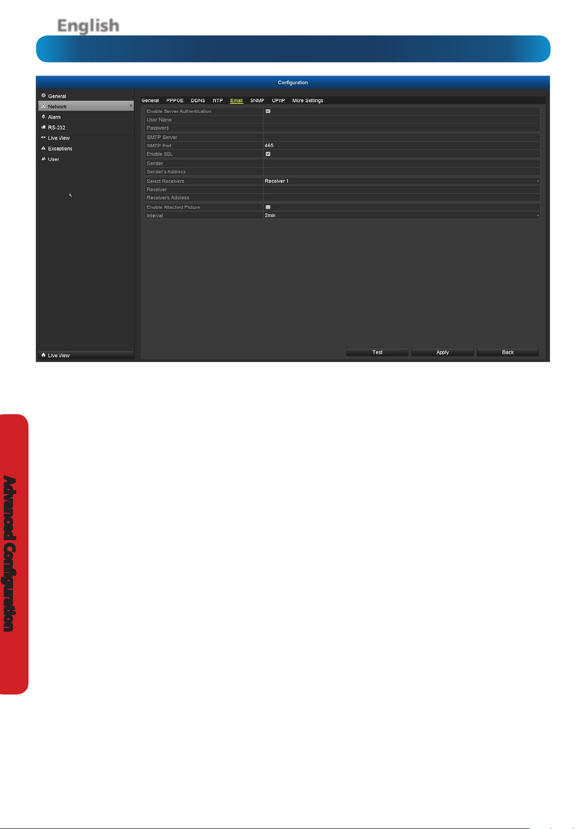
Conguration: Network: Email
Username for email account
Password for email account
smtp.gmail.com
Name for sender account
outgoing@email address
Receiver’s name
receiver@email address
Advanced Conguration
We suggest using Gmail as your email client - it’s quite easy to
set up an account and use it solely for the NVR. We’ve tested
the email procedure with Gmail, and it does work.
Other email servers may not work correctly - many interpret
the procedurally generated email from the NVR as spam and
block the mail from being sent.
For the Auto-Mail function to work correctly, the NVR will need to
be correctly congured with the details of the email servers and
addresses you want to use.
Enable Server Authentication: If your outgoing mail server
requires authentication, ensure this box is checked.
User Name: The username for the outgoing email account.
Password: The password for the outgoing email account.
SMTP Server: The name of the SMTP server of the email provider
that you have selected. Here are the SMTP server names for Gmail
(Google), Yahoo Mail and Windows Live Mail (Hotmail):
Gmail (Google): smtp.gmail.com
Yahoo Mail:
Windows Live Mail (Hotmail):
smtp.mail.yahoo.com
smtp.live.com
You’ll need to setup an account with one of these email providers.
All oer free email accounts. To signup, visit the email provider’s
website:
Gmail (Google): www.gmail.com
Yahoo Mail:
Windows Live Mail (Hotmail):
www.mail.yahoo.com
www.hotmail.com
SMTP Port: The SMTP port used by the email provider of your
choice. The SMTP port for Gmail users is 465.
Enable SSL: Whether the email server you’re using requires a
secure link. This should be left on if you’re using any of the preset
email servers.
If you want to use your ISP’s outgoing email, then you’ll need to
contact your ISP to learn the correct values for the other elds
(such as the correct SMTP server, SMTP port, SSL requirements and
so on).
Sender’s Address: The address you’re sending the email from.
This will be the username you’ve set up for the email server you’re
using, followed by “@” and then the email server. For example:
“youraddress@gmail.com” or similar.
Select Receivers: You can select up to three dierent receivers to
send an email to.
Receiver’s Address: The email address you want the NVR to send
emails to. This can be any email address you like, however, bear
in mind that the NVR might send a large number of automatic
emails under certain conditions.
Enable Attached Picture: When this is selected, the NVR will
attach three small images to each email alert (where applicable).
For motion-based email alerts, this will be an image of whatever
triggered the motion detection.
Interval: The length of time that must elapse after the NVR sends
an email alert before it will send another.
Short Interval settings are likely to lead to huge numbers of
alerts being sent by the NVR - perhaps even several emails for
one event (if that one event lasts longer than the interval setting).
On the other hand, a long interval setting might mean you’ll miss
a specic update that you needed. There’s no right answer, and
you’ll probably have to ne-tune this setting to get the results
you’re after - it’ll be dierent for everyone’s unique circumstances.
40
Page 41

English
Conguration: Network: SNMP/UPnP
SNMP (Above)
SNMP: Simple Network Management Protocol. If your
network is setup to use SNMP (if you’re not sure, your network
administrator(s) should be able to tell you if this protocol is in
use) then you can congure it here.
Enable SNMP: Whether SNMP is in use. If it’s not in use, then
ensure this stays disabled. The SNMP protocol can interfere
with normal networking functionality.
SNMP Version: The version of SNMP currently being used.
SNMP Port: The SNMP port currently being used. This is
typically port 161, however exceptions exist.
Read Community: Who has read-only access to information
on the network (can view, but not change).
Write Community: Who has control over information on
the network (can view, modify, change, create or delete
information).
Trap Address: The address of the network trap (the
asynchronous notication from agent to manager).
Trap Port: The port being used for the trap.
UPnP (Below)
Enable UPnP: UPnP makes conguring your network easier
and faster. To use the UPnP setting on the NVR, you’ll need a
router which supports this feature, with UPnP enabled. Note
that many routers which do support UPnP do not come with
the feature enabled by default. You may need to ask your
Internet service provider to turn it on.
When UPnP is enabled on your NVR and your router, the Ports
that the NVR requires to be open for access to and from the
Internet will automatically be opened and closed as necessary
by your router, saving you the trouble of manually forwarding
these ports. If UPnP is not enabled, or your router does not
support this feature, you’ll need to forward the ports the NVR
uses from the router to the NVR - since this is a technically
challenging process; we strongly recommend using UPnP if
possible. Make sure that the number used for the External
Port and Internal Port match, otherwise the UPnP function
will not work.
Edit: Allows you to change the current External Port number.
Mapping IP Address: Will display the public IP address of the
router that the NVR is connected to.
Status: If UPnP is working correctly, you will see Active
displayed. If UPnP is not enabled or you haven’t forwarded the
correct port number, the status will be Inactive.
Advanced Conguration
41
Page 42

English
Conguration: Network: More Settings
Advanced Conguration
Alarm Host IP: The location on your network where an IPbased alarm system is hosted.
Alarm Host Port: The port associated with the IP-based alarm
system.
Server Port: This is the internal port that the NVR will use to
send information through. The most important things are:
• You’ll need to enable UPnP on your router so your router
can selectively open these ports, allowing the NVR to
communicate via the Internet. If your router doesn’t
support UPnP, you have two options. You can either get
a new router (which we’d actually recommend - UPnP
is such a good feature!) or you can manually forward
ports from the router to the NVR. Port forwarding is a
technical and involved process, recommended only for
the technically inclined.
• Nothing else uses this port. The default port number is
8000, which is not used by many other devices/programs.
However, particularly if you have another NVR or NVR-like
device, something might be using this port already. If this
is the case, change this value to be unique.
• You’ll need to know this port value when logging
within your network or remotely - so, if you change it,
remember what it is!
• Make sure that the number used for the External Port
and Internal Port match, otherwise the UPnP function
will not work.
• You’ll need to know this port value when logging
within your network or remotely - so, if you change it,
remember what it is!
Multicast IP: Multicast IP is a technique for one-to-many
and many-to-many real-time communication over an IP
infrastructure in a network. The receiver will receive data from
that IP without the need to contact individual devices directly.
In most circumstances this option is not required.
RTSP (Real-Time Streaming Protocol) Port: This port is
used to stream real-time images through, and is the port that
will be used to communicate with mobile devices. If you are
having issues streaming video to your mobile device or your
mobile service provider is blocking access, we recommend to
change this value to 5554. Do not change this if everything is
working ok.
What port number(s) should I use?
If the default port numbers are in use (85 and/or 8000) then the
simplest solution is just to keep “adding one” until you nd a port
which is not in use. So, if 85 is already taken, try 86 or 87.
There’s no “right” port number(s) to use - any port number will
work provided the NVR is the only device using it. For this reason,
avoid using port numbers 80, 81, 82, 88, 90, and 99 as these
are often used by other devices/programs/protocols.
HTTP Port: This is the port through which you will be able to
log in to the NVR.
• Like the RTSP port, it will need to be forwarded properly
in order to ensure smooth, latency-free communication.
The default value is “85”, as this port is seldom used by
other devices or applications. If there is another device on
your network using this port, you’ll need to change it to
be unique.
42
Page 43

English
Conguration: Alarm: Alarm Status
The Conguration: Alarm: Alarm Status menu displays the
current status and conguration of the Alarm Input and Alarm
Output connections.
Advanced Conguration
43
Page 44

English
Conguration: Alarm Input
Advanced Conguration
The Alarm Input menu will allow you to customize and congure
how you’d like the NVR to interpret input from and respond to the
sensor input panel on the rear of the NVR.
Alarm Input No.: The connection that corresponds to the input
you’ve connected the sensor to. Note that the Alarm Input
Number and the Channel Number don’t have to be the same. The
<- characters indicate that these are alarm inputs.
Alarm Name: The name you want to associate with the alarm. We
suggest something descriptive and useful, such as “Lounge Room
PIR Sensor” or “Front Door Sensor”. The NVR will use this name in
email alerts and in the event log to let you know where alarms are
being generated.
Type: Whether the sensor is a NO (normally open) or NC (normally
closed). You’ll need to check your sensor’s documentation to learn
the correct value to use. It refers to the way the sensor tells the
NVR when it has detected something. If this is set to the wrong
value, you’ll get constant “false” alarms, which will stop only when
the sensor detects something.
Conguration: Alarm Output
Setting: Tick this check-box to enable the Alarm Input.
Handling:
alarm input has been alerted.
Please note: depending on the conguration and intended
purpose of your external alarm device, it may or may not
continue to be in an alarmed state once the NVR’s signal has
ceased.
If you enabled an action for a sensor input and set the sensor
type to NO and don’t have a sensor connected to the NVR, then
this will constantly trigger alarm events.
Here you can dene what will happen when the
Here you can control the operation of the NVR’s Alarm Out
port. Note that the alarm output(s) on the NVR is Normally
Open (NO). If you’ve got an external device, it must be
congured to use a NO triggering method; otherwise they’ll
be in a permanently alarmed state.
Alarm Output No.: The connection that corresponds to the
output you’ve connected an external device to.
44
Alarm Name: The name you want to associate with the alarm.
Dwell Time: The amount of time you’d like the NVR to maintain
the Alarm Output status.
Handling: Here you can dene what will happen when the
alarm output(s) has been alerted.
Page 45

English
Conguration: RS-232
The Conguration: RS-232 menu will allow you to change
settings for the RS-232 port. It is mainly used for low level
testing and is not required for day to day use.
Conguration: Live View
Video Output Interface: The default output is VGA/HDMI.
Live Video Mode: 4 x 4 is the default mode for live video
mode. This will display up to 16 video channels on-screen at a
single time. Selecting 1 x 1 will display the rst video channel
full-screen. Other views available are 2 x 2, 3 x 3, 1 + 5 and 1
+ 7.
Dwell Time: The time in seconds to dwell on a video channel
when enabling Start Auto-switch in Live View. This only
works when the Live Video Mode is set 1 x 1.
Enable Audio Output: As the cameras supplied with the NVR
do not support audio capture, this option is not required.
Event Output: The default output is VGA/HDMI.
Full Screen Monitoring Dwell Time: The time in seconds to
show an alarm event screen.
Advanced Conguration
45
Page 46

English
Conguration: Live View: View
Advanced Conguration
In Live View, you can change the display order of each camera
connected -
1. Select an available viewing window on the right-hand side.
2. Double click one of the available cameras on the left-hand
side that you would like to place in the viewing window that
you have selected.
Play: Pressing the Play button will start the live view of all
cameras connected to the NVR.
Stop: Pressing the Stop button will stop the live view of all
cameras connected to the NVR.
Please note: Pressing the stop button means that you will
not see a real-time view of all the cameras connected to the
NVR at the main viewing screen. Press the play button to
enable real-time view.
46
Page 47

English
Conguration: Exceptions
An Exception is any deviation from the NVR’s normal
behaviour - phrased another way, it’s like saying the NVR’s
been working ne except for these events
Exception Type: What event type you’d like the NVR to react
to. By conguring the Action for these events, you can create
any combination of audio alerts (see below) or auto-emails to
be sent for dierent event types.
HDD Full: As the name suggests, this event occurs when the
NVR runs out of space on the hard drive to save new footage.
This event is redundant if you’ve got overwrite enabled, as
the NVR will automatically delete old footage to ensure it can
continue to record.
HDD Error: Occurs when the NVR has trouble accessing its
hard drives, or when it cannot detect one at all.
Network Disconnected: Will occur if the NVR has problems
connecting to the Internet. This may indicate a problem
with the NVR’s conguration, a fault with your network or a
problem with your Internet Service Provider (ISP).
IP Conicted: This event will occur if the NVR detects another
device on the same network with a conicting IP address. It’s a
little like two houses with the same number being on the same
street - one house might get the other’s mail, or get woken up
at all hours of the night being asked if someone named “Big
Bob” lives there.
Illegal Login: This will occur if the NVR detects a login with an
incorrect username or password.
Record/Capture Exception: This will occur if there are
unexpected errors during capture such as a HDD failure, if the
HDD is full or if the HDD quota has been changed.
Audible Warning: The NVR will use its internal buzzer to emit
an alarm tone. It sounds like an old computer indicating an
error, or a large truck backing up.
Alert CMS Software: A warning message is sent to the
SwannView Plus client software installed on the computer.
Send Email: The NVR will send an auto-email alert when the
event type you’ve selected occurs.
Trigger Alarm Output: Instructs the NVR to output an alarm
signal from the alarm output terminal(s). The alarm output(s)
must be correctly connected and congured.
Advanced Conguration
Basically, it indicates that two devices are trying to use the
same IP address. This shouldn’t occur if you’re using DHCP
addressing, unless one or more devices is set to use a STATIC
IP (the static addressing method overrides the automatic
assignment process).
47
Page 48

English
Conguration: User
Advanced Conguration
The Conguration: User menu is where you can dene and
congure the dierent levels of access various users have to
the NVR.
We suggest that at minimum the admin account be password
protected, as it has access to all aspects of the NVR’s operation.
To add additional users, choose Add.
To customize a user’s level of access, choose Edit.
To remove a user, choose Delete.
User’s MAC Address: To restrict remote user access, you can
input the MAC address of the remote computer that will be
used to access NVR. The NVR will only allow remote access
from a computer with this MAC address to gain access.
You cannot modify the access level of the default admin
account - they can do everything.
This is to prevent an unfortunate incident where, for example,
no user has the permissions required to change another user’s
permissions - which could lead to the NVR being, in at least
some senses, inoperable.
48
Page 49

English
System Maintenance: System Info
If you’re looking at the System Information screen, you’ve
probably been directed to do so by Swann Technical Support.
If we haven’t told you to come here, you might be wondering
what all the information means. On a day-to-day level, the
answer is “very little”. However, if you’re still curious:
Device Info: Displays the Device Name, Model, Serial Number,
Firmware and Encoding Version of the NVR.
Camera: Displays the cameras connected to the NVR.
Record: Displays the current recording settings.
Alarm: Displays the current alarm status.
Network: Displays the current network settings.
HDD: Displays the current status of the hard drive(s) installed
or connected.
Advanced Conguration
49
Page 50

English
System Maintenance: Log Information
Advanced Conguration
The System Maintenance: Log Information menu contains
information for operation, alarm, exceptions and information
of the NVR.
1. Set the log search conditions to rene your search including
the Start Time, End Time, Major Type and Minor Type.
2. Click the Search button to start searching the log les.
3. The matched log les will be displayed. Up to 2000 log les
can be displayed each time.
4. Double click each le to view detailed information contained
in the log.
5. Click the Play button to view the video that is related to that
log le.
6. If you want to export the log le, click the Export button to
enter the Export menu. Click the Search button rst otherwise
the Export button will not be active.
7. Select the backup device from the Device Name dropdown
list. Click New Folder to create a new folder or Format to
format the backup device. Click Export to export the log les
to the backup device.
To export all the log les, click the Log Export option, select
the hard drive that you want to export, select the backup
device from the Device Name dropdown list, then click the
Export button.
50
Page 51
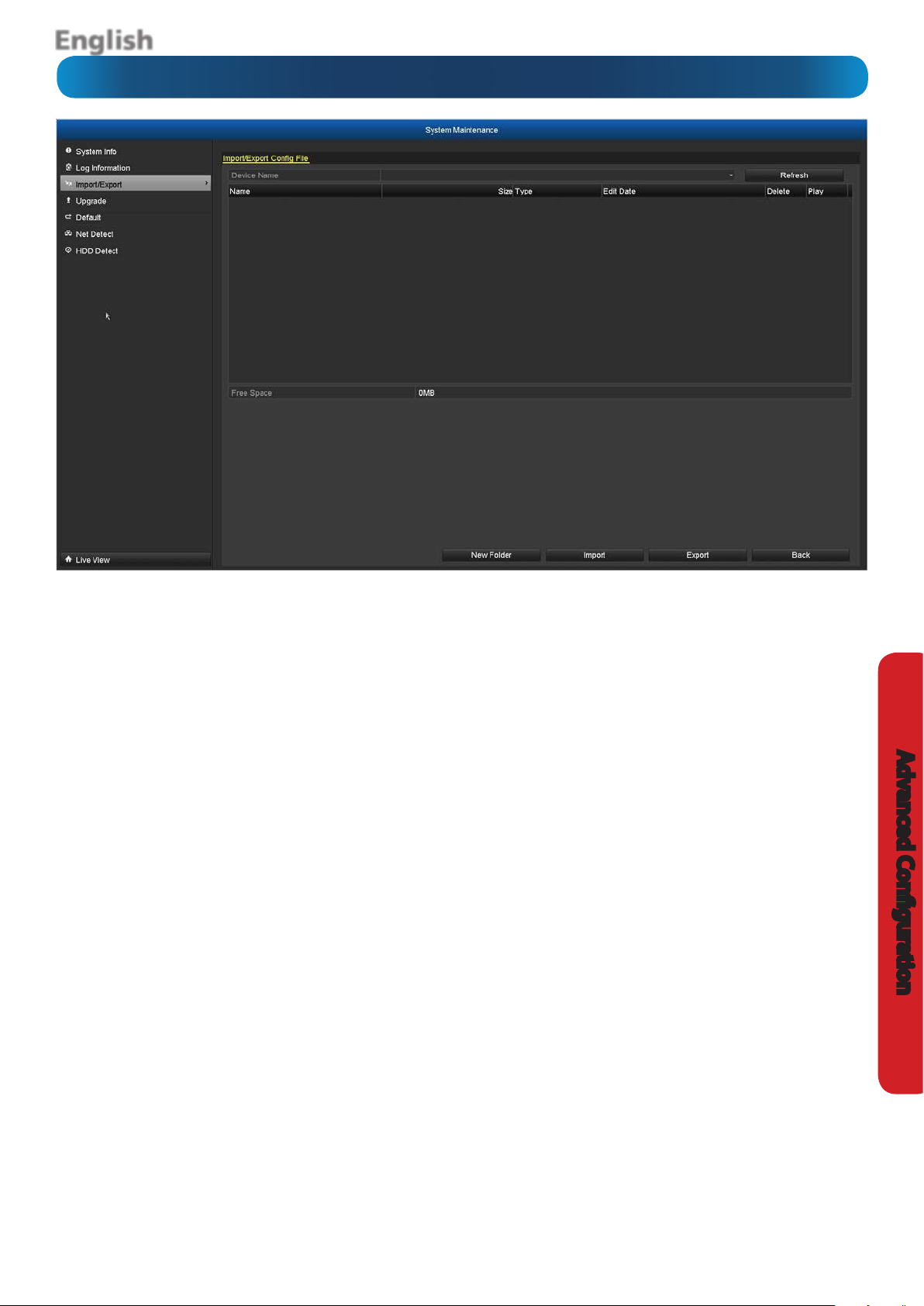
English
System Maintenance: Import/Export
The System Maintenance: Import / Export menu allows you
to import or export your current conguration settings. This
will come in handy as it will save you time if you have to reset
the NVR back to factory default settings.
To export your current conguration le, select the backup
device from the Device Name dropdown list. Click New
Folder to create a new folder or Format to format the backup
device. Click Export to export the conguration le to the
backup device.
To import a previously saved conguration le, select the
backup device from the Device Name dropdown list. Select
the conguration le - it will be called devCfg_(serial
number)_(year/month/time).bin, then click the Import
button. After the conguration le has been imported, the
NVR will reboot automatically.
Advanced Conguration
51
Page 52

English
System Maintenance: Upgrade
Advanced Conguration
The System Maintenance: Upgrade menu allows you to
upgrade the rmware of the NVR. You’ll only need to use these
options if instructed to do so by Swann Technical Support.
Local Upgrade: The rmware will be updated locally using a
USB Flash Drive or USB Hard Drive. Click the Upgrade button
to commence the update.
FTP: The rmware will be updated using your computer as a
FTP server. Make sure that both your computer and NVR are
connected to the same Local Area Network (LAN). You will need
to download and install 3rd party TFTP software onto your
computer. Place the rmware le into the root directory of the
TFTP software and input the IP address of your computer into
the NVR. Click the Upgrade button to commence the update.
52
Page 53

English
System Maintenance: Default
The System Maintenance: Default menu allows you to reset
the NVR and load factory default settings. There are two
options available - you can select the rst option which will
reset all the parameters including network and user settings,
or you can select the second option which will do the same
but will maintain your network and user settings. The NVR will
reboot after pressing the OK button. Please note, all data on
the HDD will remain.
Advanced Conguration
53
Page 54

English
System Maintenance: Net Detect
Advanced Conguration
The System Maintenance: Net Detect menu allows you to
check network trac and to obtain real-time information
from the NVR such as network detection, network status and
sending and receiving network trac.
54
Page 55

English
System Maintenance: HDD Detect
The System Maintenance: HDD Detect menu will display
technical specications of the hard drive(s) installed. If you’re
looking at this screen, you’ve probably been directed to do so
by Swann Technical Support.
System Maintenance: HDD Detect: Bad Sector Detection
The System Maintenance: HDD Detect: Bad Sector
Detection menu allows you to do a test on the hard drive(s)
for bad sectors. If you’re looking at this screen, you’ve probably
been directed to do so by Swann Technical Support.
Advanced Conguration
55
Page 56

English
Troubleshooting
Q: I can’t login to or unlock the NVR - it says my password is
wrong.
A: The default username/password combination for the NVR
is “admin” with the password “12345”. If that doesn’t work (and
you haven’t set a password of your own that you’ve forgotten)
then something strange has happened - contact Swann
technical support (contact details are on the rear cover).
Q: The NVR will boot up and show live images, but there are no
menus being displayed. Why?
A: There might be a fault with one (or more) of the hard drives
installed in the NVR. Before the menu system is displayed, the
NVR attempts to detect what drives are connected. If there is
an ambiguous signal preventing the NVR from ascertaining
whether there is a drive connected or not, then it will keep
looking and waiting for the drive to respond.
If you’ve just installed a new drive, disconnect it and see if that
xes the problem. You can also try disconnecting one drive at
a time to see if that one is the culprit.
Q: How do I eliminate false-triggers on my motion detection?
A: There’s no guaranteed way to eliminate false triggers, but -
in the majority of cases - you can ne-tune the NVR’s motion
detection settings to reduce the number of false triggers
you’re likely to get. (See “Camera Management: Motion” on
page 28 for more detailed information about setting motion
detection.)
Q: I’m getting too many email alerts from the NVR.
A: There are a few things that might help, depending what’s
generating the email alerts. Here are a few possibilities:
• The emails are for real events, however it is telling me
about it multiple times.
This indicates that the NVR is functioning properly, but that
the Interval setting for your email alerts is too low. Increasing
the Interval time will decrease the number of email alerts the
NVR sends.
• The NVR sends email alerts when nothing seems to be
happening.
This suggests that there might be something amiss with your
Motion Detection settings, or with the conguration of your
sensors (if used).
The most likely explanation is that there is something in view
of your cameras which is moving, or causes the illusion of
movement. Have a look at “Camera Management: Motion” on
page 28 for some more information.
• The NVR keeps reporting errors (such as Video Loss,
HDD Error or similar).
There seems to be a hardware or conguration fault with the
NVR. These are most often caused by a faulty (or simply poorly
connected) connection or cable. Check the integrity of your
cables and connections.
1. Mask any redundant movement. This includes obvious
things like trees blowing in the wind, roads with cars passing
and so forth. Some less obvious things which might cause
false triggers include: the “ickering” of screens, monitors
or uorescent lights, reections of movement in windows/
mirrors and so on, lights which are often turned on or o,
shadows passing and so on. We can’t possibly imagine what
you’re going to nd in your unique circumstances, so we
encourage you to experiment.
2. Fine-tune your sensitivity. There’s no substitute for getting
a volunteer to play the part of intruder and experimenting.
Some cameras are just more “touchy” than others; some
lighting conditions are harder to get the settings “right” for.
3. Adjust your image settings (see “Camera Management: Image”
on page 27). Unlike many image adjustment options, the NVR
pre-processes video, which means that, when the NVR looks
Reference
for motion, it’s looking at your already processed images. By
reducing the amount of video noise in your image, you can
increase the accuracy of the motion detection dramatically.
Typically, the settings that most often require adjustment are
Brightness and Contrast.
Video noise is a problem with any video signal. It’s the very
slight change in brightness and/or color of pixels between
frames, and it’s commonly regarded as being “just one of
those things” when dealing with digital imaging. By tweaking
the brightness and contrast, you can usually remove a good
deal of this noise, as it tends to be most pronounced near the
blacks (the really dark bits) and the whites (the really bright
bits) of your images.
Q: I would like to use other network connected cameras with
the NVR, is this possible?
A: The NVR is guaranteed to work with Swann branded
network cameras only.
56
Page 57

English
Addendum: Third Party Hardware
Due to its nature as a networked device, the NVR is often
required to operate with third party hardware. We do
everything we can to ensure the NVR is compatible with as
many third party devices as possible; there will always be
some that require a little extra conguration.
Routers
I’m using a router which doesn’t support DHCP addressing.
or
Some devices on my network require STATIC addressing.
You’ll need to set the address of the NVR manually. You’ll need
to:
• Find Your Network’s IP Address Range
• Create a Unique IP Address
• Assign the IP address information to the NVR.
Finding your Network’s IP Address Range
First, you’ll need to know the IP address, Subnet Mask and
DNS Server of at least one other device on your network. It’s
easiest to nd these addresses by using a computer on the
same network.
For Windows-based PCs:
• Open the Start Menu, navigate to Accessories and open
Command Prompt.
Assigning the IP Address information to the NVR.
We recommend doing this locally (on the NVR itself) even if you
can access the NVR via the network (using the SwannView Plus
client software) in the meantime.
If you’re connected remotely and the networking information
changes, you might lose the connection to the NVR.
• Open the Conguration: Network menu on your NVR
(see page 37).
• Select Static addressing.
• IP Address: Enter the unique IP that you created for the
NVR here.
• Subnet Mask: Enter the same value as the computer’s
Subnet Mask.
• DNS Server: Enter the same value as the computer’s DNS.
The NVR should now be accessible via your local network.
Before you can access the NVR remotely, you’ll need to
Forward Ports (STATIC addressing does not support UPnP,
see below).
I’m using a router which doesn’t support UPnP. How do I
“forward ports”?
It depends on what type of router you have. There’s no
standard procedure for forwarding ports - each manufacturer
has their own user interface and procedure for customising
the behaviour of the router.
• Type “ipcong” and press Enter.
• Your IP Address information will be displayed.
For Mac-based systems:
• From the Apple menu, select System Preferences.
• Click on the Network pane.
• Click on the Advanced button and look under the TCP/IP,
DNS, and Ethernet tabs.
Creating a Unique IP Address
The IP Address of your computer will be made up of four
groups of numbers, separated by periods: aaa.bbb.ccc.ddd
The rst three groups of numbers (aaa.bbb.ccc) must be the
same as the other device on your network. The last number
(ddd) must be changed to something unique that nothing else
on your network uses.
For example:
If your computer’s IP address is 192.168.1.10, then a suitable
unique IP address for your NVR will be 192.168.1.210
Note: Each number in the IP address cannot exceed 255.
First, check the router’s documentation - the instructions may
be there.
If your router’s documentation doesn’t describe the method
for port forwarding, then open a web browser and navigate
to www.portforward.com - they’ve got instructions on port
forwarding for (literally) thousands of dierent routers.
We can’t oer much more information about forwarding ports
here, as this is a process totally dependent on third-party
hardware. If you do run into trouble, we suggest contacting
the manufacturer of the router.
Alternately, if you’re using an older router which doesn’t
support UPnP, then it might be time for an upgrade - modern
routers are increasingly powerful and are (in most cases) easier
than ever to setup. We think that UPnP is a fantastic feature
that’s well worth having, not just for NVRs.
Reference
57
Page 58

English
Warranty Information
USA
Swann Communications USA Inc.
12636 Clark Street
Santa Fe Springs CA 90670
USA
Swann Communications warrants this product against defects in workmanship and material for a period
of one (1) year from its original purchase date. You must present your receipt as proof of date of purchase
for warranty validation. Any unit which proves defective during the stated period will be repaired without
charge for parts or labour or replaced at the sole discretion of Swann. The end user is responsible for all
freight charges incurred to send the product to Swann’s repair centres. The end user is responsible for all
Swann Communications
Unit 13, 331 Ingles Street,
Port Melbourne Vic 3207
Australia
Warranty Terms & Conditions
Australia
Swann Communications LTD.
Stag Gates House
63/64 The Avenue
SO171XS
United Kingdom
United Kingdom
shipping costs incurred when shipping from and to any country other than the country of origin.
The warranty does not cover any incidental, accidental or consequential damages arising from the use of
or the inability to use this product. Any costs associated with the tting or removal of this product by a
tradesman or other person or any other costs associated with its use are the responsibility of the end user.
This warranty applies to the original purchaser of the product only and is not transferable to any third
party. Unauthorized end user or third party modications to any component or evidence of misuse or
abuse of the device will render all warranties void.
By law some countries do not allow limitations on certain exclusions in this warranty. Where applicable by
Reference
local laws, regulations and legal rights will take precedence.
For Australia: Our goods come with guarantees which cannot be excluded under Australian Consumer
Law. You are entitled to a replacement or refund for a major failure and for compensation for any other
reasonably foreseeable loss or damage. You are also entitled to have the goods repaired or replaced if the
goods fail to be of acceptable quality and the failure does not amount to major failure.
58
Page 59

English
Notes
______________________________________________________________
______________________________________________________________
______________________________________________________________
______________________________________________________________
______________________________________________________________
______________________________________________________________
______________________________________________________________
______________________________________________________________
______________________________________________________________
______________________________________________________________
______________________________________________________________
______________________________________________________________
______________________________________________________________
______________________________________________________________
______________________________________________________________
Reference
______________________________________________________________
______________________________________________________________
______________________________________________________________
59
Page 60

English
Helpdesk / Technical Support Details
Swann Technical Support
All Countries E-mail: tech@swann.com
Telephone Helpdesk
USA toll free
1-800-627-2799
USA Exchange & Repairs
1-800-627-2799 (Option 1)
(M-F, 9am-5pm US PT)
AUSTRALIA toll free
1300 138 324
NEW ZEALAND toll free
0800 479 266
UK
0203 027 0979
60
© Swann Communications 2013
 Loading...