

Page 1
GuardianEye
Monitoring System
INSTRUCTION MANUAL
Page 2

2
Important Information
FCC Verification
This equipment has been tested and found to comply with the limits for
Class B digital device, pursuant to part 15 of the FCC Rules. These limits
are designed to provide reasonable protection against harmful interference in a residential installation. This equipment generates, uses and
can radiate radio frequency energy and, if not installed and used in accordance with the instructions, may cause harmful interference to radio
or television reception, which can be determined by turning the equipment off and on, the user is encouraged to try to correct the interference
by one or more of the following measures:
• Reorient or relocate the receiving antenna
• Increase the separation between the equipment and the receiver
• Connect the equipment into an outlet on a circuit different from that
to which the receiver is connected
• Consult the dealer or an experienced radio/TV technician for help
These devices comply with part 15 of the FCC Rules. Operation is subject to the following two conditions:
• These devices may not cause harmful interference
• These devices must accept any interference received, including interference that may cause undesired operation
Important Notice - All jurisdictions have specific laws and regulations
relating to the use of cameras. Before using any camera for any purpose, it is the buyer’s responsibility to be aware of all applicable laws
and regulations that prohibit or limit the use of cameras and to comply
with the applicable laws and regulations.
FCC Regulation (for USA): Prohibition against eavesdropping
Except for the operations of law enforcement officers conducted under
lawful authority, no person shall use, either directly or indirectly, a device operated pursuant to the provisions of this Part for the purpose
of overhearing or recording the private conversations of others unless
such use is authorized by all of the parties engaging in the conversation.
Warning - Changes or modifications made to this device not approved
expressly by the party responsible for compliance could void the user’s
authority to operate the equipment.
Important Safety Instructions
• Make sure product is fixed correctly and stable if fastened in place
• Do not operate if wires and terminals are exposed
• Do not cover vents on the side of the device and allow adequate space
for ventilation
• Only use the power adapter supplied with your NVR
Password Information
Your NVR does not have a default password. A password is created during the Wizard. If password protection has been enabled and you have
forgotten your password, please contact Swann Helpdesk & Technical
Support for assistance (contact numbers on the last page).
About this Manual
This instruction manual is written for the GuardianEye Monitoring System and was accurate at the time it was completed. However, because
of our on-going efforts to constantly improve our products, additional
features and functions may have been added since that time. We encourage you to visit our website to check for the latest updates.
Page 3

3
Contents
Important Information 2
Contents 3
Chapter 1: Live View 4
Live View Mode 5
Live View Icons 6
Chapter 2: Menu 7
Menu Layout 8
Chapter 3: Camera Configuration 9
Recording: Encode 10
Channel: Device List 11
Motion 12
Motion: Motion Detection 13
Motion: Schedule 14
Motion Detection Tips 15
Chapter 4: Recording Configuration 16
Recording Schedule 17
Chapter 5: Playback & Backup 18
Search: Video Search 19
The Playback Interface 20
Search: Backup 21
Chapter 6: System Configuration 22
System: General 23
Daylight Saving 24
System: HDD 25
System: Maintenance 26
Network: General 27
Network: Advanced 28
Email Settings 29
Network: WIFI Setting 30
System: System Information 31
Troubleshooting 32
Glossary 34
Warranty Information 36
Helpdesk & Technical Support 37
Page 4
44
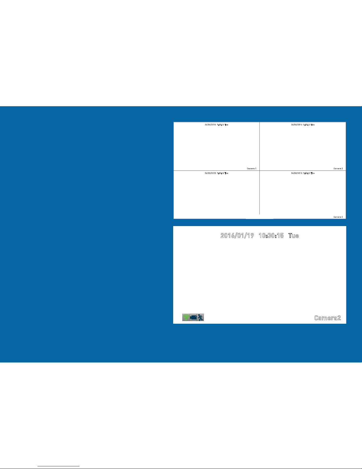
Live View
Live View is the default display mode
for your NVR. Each camera connected
will be displayed on-screen. You can
check the status or operation of your
NVR and cameras using the status
icons and Menu Bar on the Live View
screen. Right-click the mouse to ac-
cess the Menu Bar.
4
26/05/2015 9:30:15 Tue
Camera 2
26/05/2015 9:30:15 Tue
26/05/2015 9:30:15 Tue 26/05/2015 9:30:15 Tue
Camera 1
Camera 4
2016/01/19 10:30:15 Tue
Camera2
Page 5
5
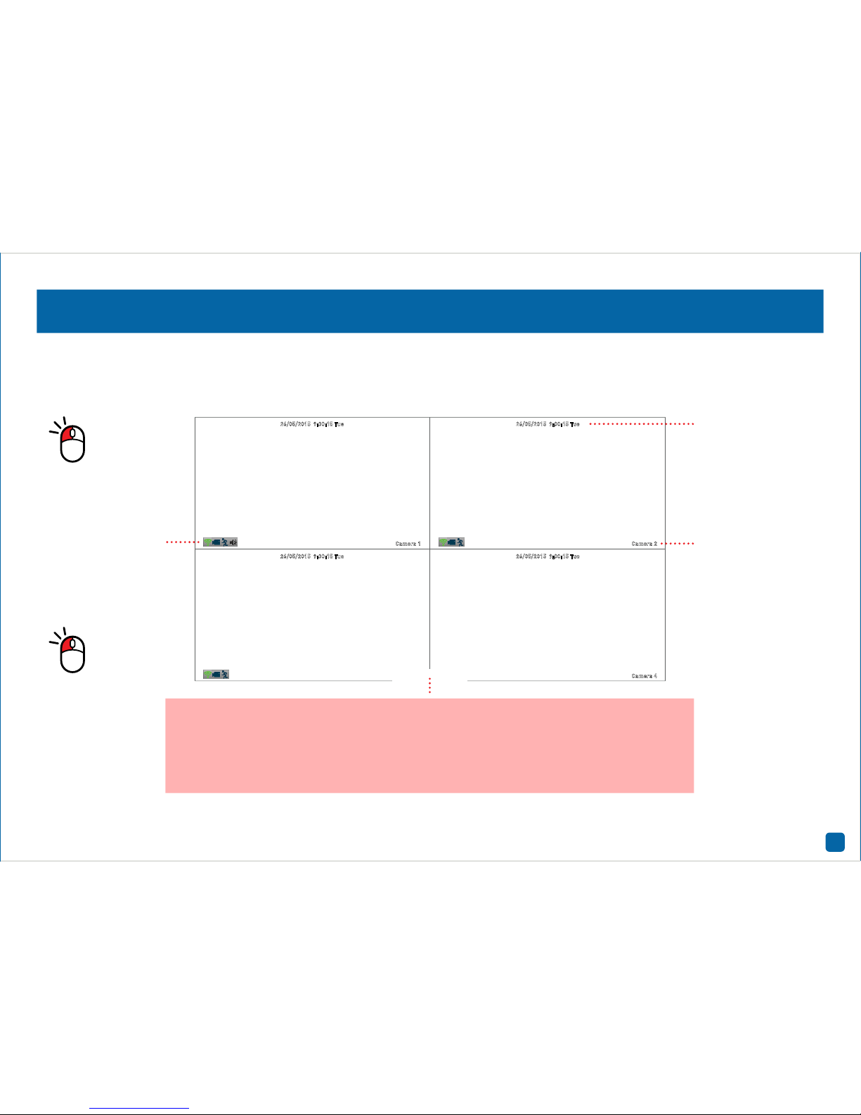
Live View Mode
Live View is the default display mode for your NVR. Each camera connected will be displayed on-screen. You can check the status or operation of
your NVR and cameras using the status icons and Menu Bar on the Live View screen (right-click the mouse to display the Menu Bar at the bottom
of the screen). You can also access the Menu to adjust settings for Recording, Motion, Network, and to search and play previously recorded videos.
26/05/2015 9:30:15 Tue
Camera 2
26/05/2015 9:30:15 Tue
26/05/2015 9:30:15 Tue 26/05/2015 9:30:15 Tue
Camera 1
Camera 4
Camera Name
Date & Time
Status Icons
Menu - Opens the Menu.
Channel - Opens the Device List which displays
your cameras that are currently connected.
Search - Click to search and playback previ-
ously recorded videos.
Audio - Click to enable or disable live audio
playback. Only one video channel can be enabled at a time.
Shutdown - Click to Lock (password must be
enabled), Shutdown or Reboot your NVR.
Click & drag a
video channel to
reposition it.
Double-click a
video channel to
view full screen.
Page 6
6
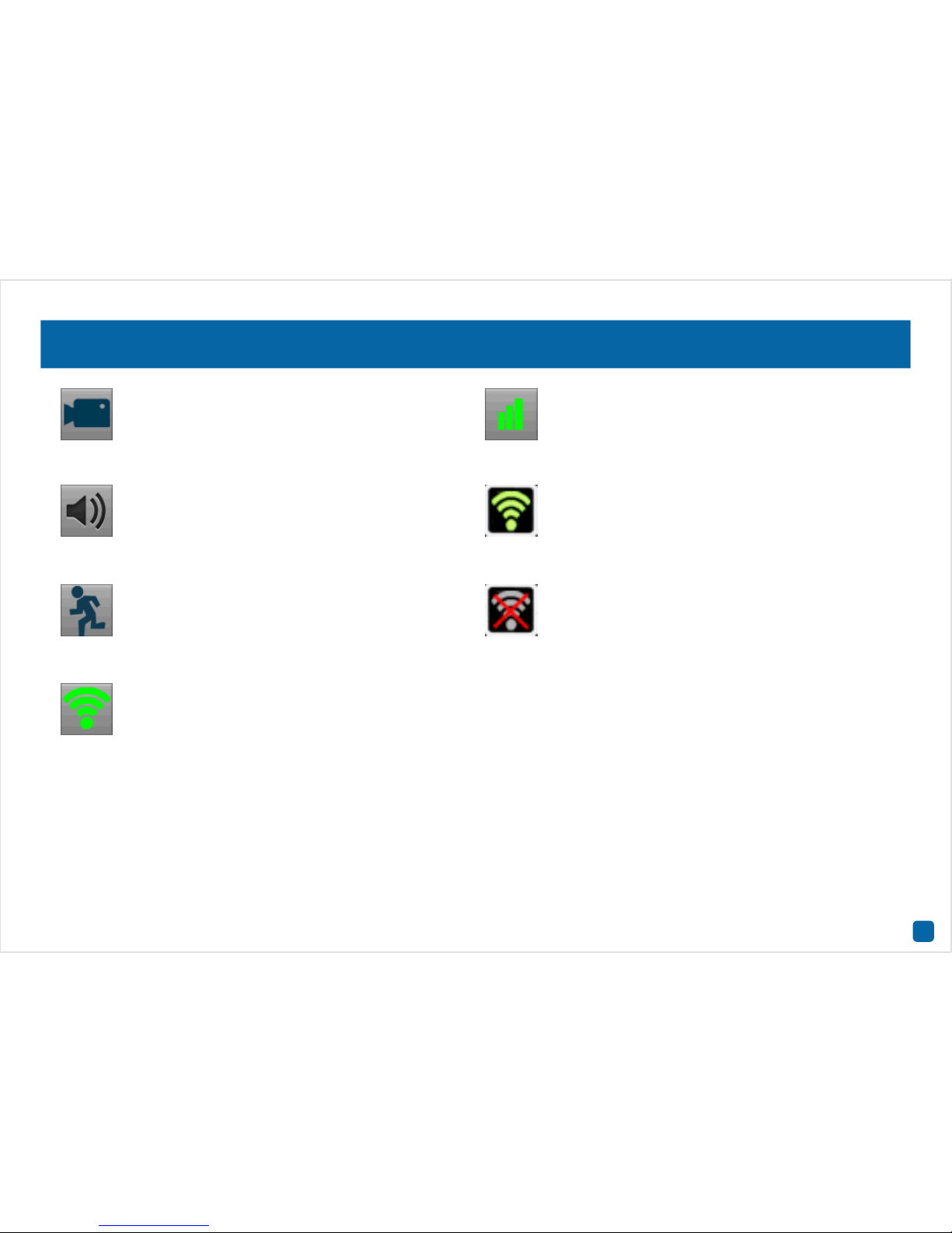
Live View Icons
The record icon indicates that your NVR is currently recording the camera’s video stream.
The audio icon indicates that the camera is selected for
live audio (click the “Audio” button on the Menu Bar to
enable).
The motion icon indicates that your NVR is detecting
motion from the camera.
This Wi-Fi icon indicates that the camera is communicating wirelessly with your NVR. The icon may change
indicating the strength of the Wi-Fi signal (strong, medium or weak).
The network icon indicates that the camera is physically
connected to your network via its LAN connection.
This Wi-Fi icon indicates that your NVR is running in Station mode and is wirelessly connected to your network.
The icon may change indicating the strength of the Wi-Fi
signal (strong, medium or weak).
This indicates that the channel displaying
this message, has lost the feed from its
camera.
This Wi-Fi icon indicates that your NVR has been disconnected from your wireless network.
Page 7

7
Menu
The Menu is where you control the
various actions and options that are
available on your NVR, such as ad-
justing settings for motion detection
and changing network modes. You can
also access previously recorded video
for playback and to export to a USB
storage device such as a flash drive.
To maintain system integrity, a firm-
ware upgrade can be performed when
available.
77
Page 8
8
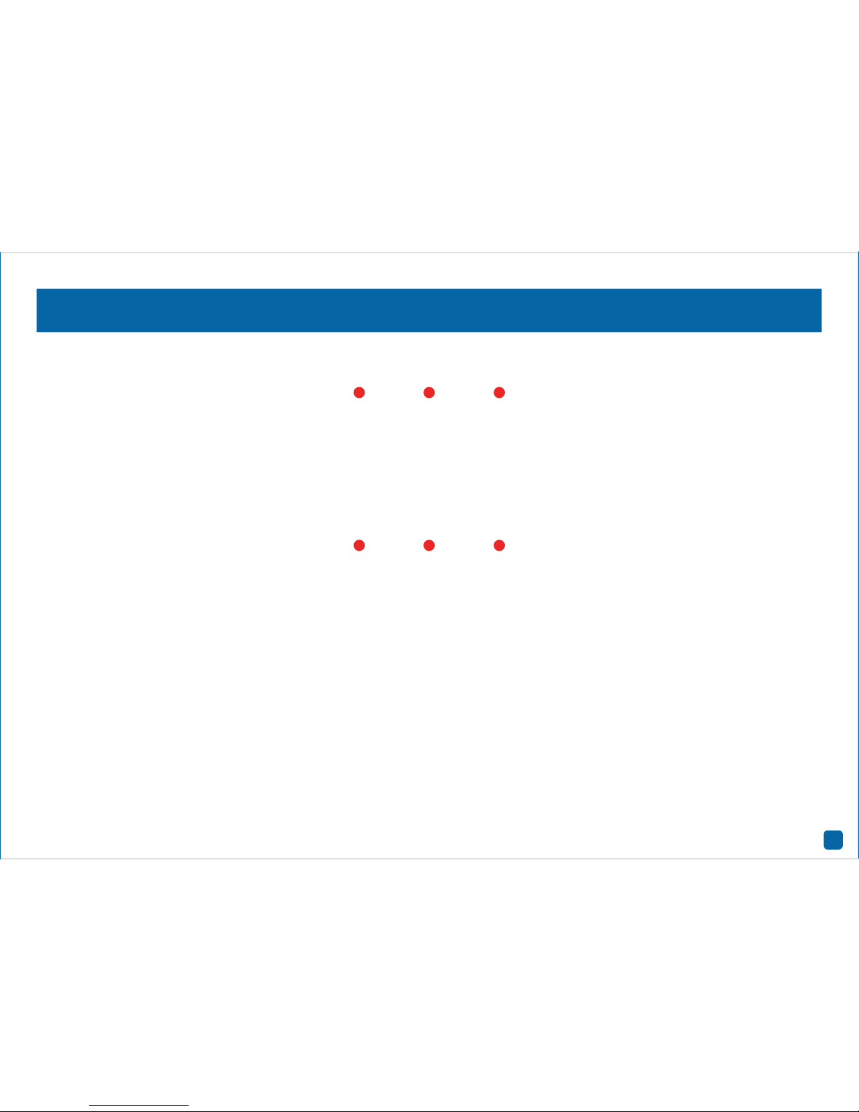
Menu Layout
By right-clicking the mouse, you can access the Menu to play back previously recorded videos, to adjust settings for motion detection and to
change system settings or upgrading the firmware.
1. Recording: This function allows you to adjust settings for the cam-
era such as camera name, encoding settings for Main Stream and Sub
Stream as well as changing the bitrate and frame rate. You can also
change the schedule for both normal and motion recording.
2. Search: This function allows you to search and play back previously
recorded videos. You’re presented with an overview of video recorded on
a particular day for a particular month for each channel on your NVR.
You can also create a backup to a USB flash drive.
3. Motion: Motion is the default recording mode for your NVR. The en-
tire view of the camera is enabled to detect motion however you can
select certain areas if you wish. The sensitivity and schedule can also
be changed according to your needs. When motion is detected, you can
enable your NVR to send you an email notification.
4. Network: This function gives you access to the various network op-
tions available including your email settings. The option to change to
Station mode can also be done here.
5. System: This function gives you access to the various system settings
such as language selection, display resolution, Daylight Saving, formatting the hard drive and upgrading the firmware.
6. Wizard: Click this to access the Wizard.
1 2 3
4 5 6
Page 9

9
Camera Configuration
The camera configuration options
are available in the “Recording” and
“Motion” menus and by clicking the
“Channel” button on the Menu Bar.
You can change the camera name,
alter the encoding settings for Main
Stream and Sub Stream, change the
bitrate and frame rate and assign a
different channel number for each
camera detected. The default motion
detection area and schedule can also
be changed.
9
Page 10

10
Recording: Encode
Camera No.: Select a camera that you would like to configure.
Camera Name: Give your camera a relevant name. It can be up to 16
characters in length.
OSD Display Position: Allows you to change the position of the on-screen
display. Click the “Set” button to change. Use the mouse to reposition
the camera name. Right-click the mouse then click “Save” to exit.
Record Audio: This is enabled by default. Click the checkbox if audio
recording is not required.
Encoding Parameters: Select which parameter that you would like to
configure, Main Stream or Sub Stream. By default, the SwannView Link
app and Windows software utilises the Sub Stream parameter to stream
video from your NVR to your mobile device or computer.
Resolution: The default resolution is 1080P (1920 x 1080) for Main
Stream (a lower resolution is also available). For Sub Stream the default
resolution is 640 x 360.
Max. Frame Rate(fps): For Main Stream, the default frame rate is
15fps. For Sub Stream, the default frame rate is 6fps. Increasing the
Sub Stream frame rate may improve playback quality when streaming.
Max. BitRate(Kbps): The default bitrate is 2048Kbps for Main Stream
and 160Kbps for Sub Stream. Changing the bitrate may improve playback quality when streaming.
• Click the “Default” button to revert back to default settings.
• Use the “Copy to” button to apply all settings to the other cameras.
• Don’t forget to click “Apply” to save settings.
Page 11

11
Channel: Device List
Accessing the Device List displays the cameras that are currently configured, the IP address and status for each camera as well as the ability
to assign a different channel number or to disconnect a camera (see
above right).
You can also permanently change the position the camera is viewed in
Live View mode, for example, a camera installed at the front entrance
is currently assigned to Channel4 (bottom right in Live View mode),
and you would prefer if this was positioned top left which is assigned to
Channel1 (you can change the camera position in Live View mode, however rebooting the NVR will revert back to the original position).
Channel1: Top left. Channel2: Top right.
Channel3: Bottom left. Channel4: Bottom right.
To access the Device List, right-click the mouse then click the “Channel” button.
When assigning a different channel number, each camera must have a
unique number, they cannot share a channel number.
• Click the “Refresh” button to refresh the Device List.
• Click the “Cancel” button to exit.
• Don’t forget to click “Apply” to save settings.
Page 12

12
Motion
Channel: Select a camera that you would like to configure.
Enable: Motion is enabled by default. Click the checkbox if you want to
disable motion detection.
Motion Detection: Click the “Set” button to change the default motion
detection area - see page 13 for more information.
Sensitivity: Click the “Set” button to change the sensitivity level for each
time period available.
Schedule: Click the “Set” button to change the default alarm schedule
- see page 14 for more information.
Send Email: Click the checkbox to send an email when motion has been
detected.
• Click the “Default” button to revert back to default settings.
• Use the “Copy to” button to apply all settings to the other cameras.
• Don’t forget to click “Apply” to save settings.
Page 13
13
Motion: Motion Detection
Detecting motion is an essential part of your security system. When motion has been detected by one or more cameras, a signal is sent to your
NVR, alerting you to a potential threat in your home. It does this by sending an email and sending an alert to your mobile device or computer.
The entire view of the camera is enabled, however you can select certain areas if you wish. In the above example, a detection zone has been
created for the windows and dining room entrance. Movement outside
of these zones will not be detected.
1. Right-click the mouse to access the sub-menu then click “Delete All”.
2. Click and drag to select the area that you want to create a zone for.
Multiple zones can be created. The same action also applies if you want
to delete a zone that has been created.
3. Right-click the mouse to access the sub-menu then click “Sensitivity”
to adjust the sensitivity level (see above) if required.
4. Right-click the mouse to access the sub-menu then click “Save” to
save any changes that you have made. To revert back to default settings
click “Add to All” or click “Cancel” to exit.
• Click the “Default” button to revert back to default settings.
• Don’t forget to click “Apply” to save settings.
• Click “Cancel” to exit.
Using the “Sensitivity” function, you can
change the motion sensitivity for each time
period available. Move the slider left or right
to change the sensitivity level.
2016/01/19 10:30:15 Tue
Camera4
Page 14

14
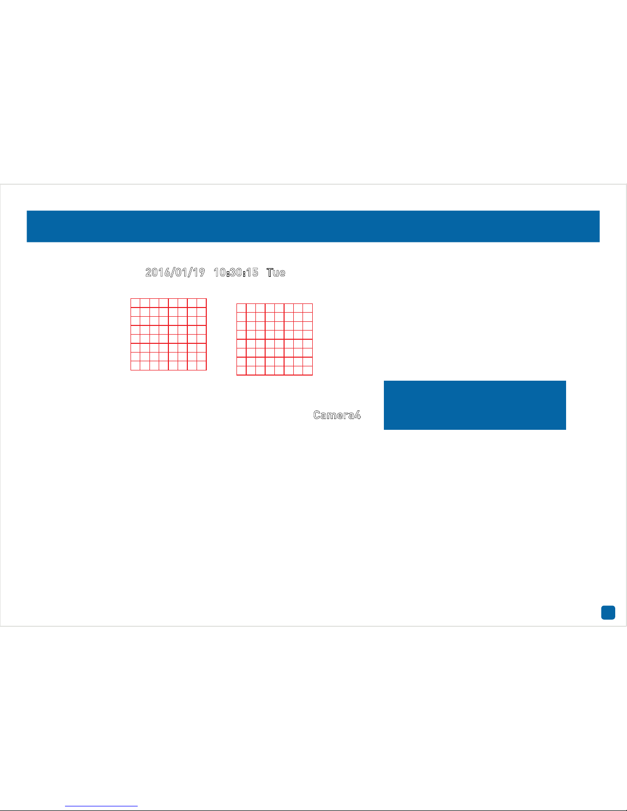
Motion: Schedule
The schedule is presented as a 24 hour 7 days a week grid and is colour
coded to represent the event type. By default, a motion detection alarm
schedule has been enabled for each camera. You can however change
the schedule according to what fits in with your needs.
In the above example, a schedule has been created for 06:00 a.m. to
06:00 p.m. Sunday to Saturday. Using the mouse, click and drag the
mouse over the squares corresponding to your desired time period.
• Click the “Default” button to revert back to default settings.
• Don’t forget to click “Apply” to save settings.
• Click “Cancel” to exit.
Page 15

15
Motion Detection Tips
Placement of the cameras
1. Keep cameras 10 to 15 feet (3 to 4 metres) away from heating vents, where the sunlight shines in, and
radiators. If a camera detects a swift change in motion, even that of a cloud passing quickly over direct
sunlight shining into your living room, Motion Detection could be activated.
2. Place cameras in areas where people have to walk through, like the stairwell, main hallway or entry
door. That way, an intruder will activate Motion Detection regardless of where they are headed. Intruders
usually go right for the master bedroom, so put a camera near that room or other rooms where you have
valuables, like the study.
3. Walk through your house and assess where intruders are most likely to enter, and what path they would
take. Most burglars enter the home through a front or back door, so it’s advisable to place the cameras
near those areas.
4. When installing cameras outside, it’s important to keep your front and backyard well-lit for ideal night
vision and the ability to detect motion. It’s common for intruders to enter a home through an unlocked
garage or by using a garage door opener in an unlocked car located in the driveway.
Avoiding false triggers
1. A flag or foliage that is blown by the wind - angle the camera so wind-blown objects are out of the
camera’s view.
2. Pets moving in front of the camera - lower the sensitivity level and/or point the camera into areas that
are not particular high-traffic for your pets.
3. Vehicles moving in the background - angle the camera so as to avoid movement in the background.
4. Moving air from a heater or air conditioner - angle the camera away from these sources.
5. Movement reflected off smooth surfaces such as glass - lower the sensitivity level and/or avoid pointing
the camera directly at glass surfaces.
Bedroom Backdoor
Hallways
Frontdoor
Page 16

16
Recording Configuration
The recording schedule is accessi-
ble from the “Recording” menu. From
here you can change the schedule for
each camera connected. By default, a
motion detection alarm schedule has
been enabled for each camera. How-
ever, you can change the schedule ac-
cording to what fits in with your needs.
1616
2016/01/19 10:30:15 Tue
Camera1
Page 17

17
Recording: Schedule
The schedule is presented as a 24 hour 7 days a week grid and is colour
coded to represent the event type. By default, a motion detection alarm
schedule has been enabled for each camera. You can however change
the schedule according to what fits in with your needs.
Camera No.: Select a camera that you would like to configure.
Normal: Your NVR will constantly record for a set period of time.
Motion: Your NVR will only record when motion has been detected from
one or more cameras.
None: As the name suggests, your NVR will not record.
In the above example, a motion recording schedule has been created
for 06:00 a.m. to 06:00 p.m. and a normal recording schedule for 06:00
p.m. to 12:00 a.m. Sunday to Saturday. Using the mouse, select the de-
sired recording mode (Normal, Motion or None) then click and drag the
mouse over the squares corresponding to your desired time period.
• Click the “Default” button to revert back to default settings.
• Use the “Copy to” button to apply all settings to the other cameras.
• Don’t forget to click “Apply” to save settings.
Page 18

18
Playback & Backup
The Search function gives you the abil-
ity to search and play previously re-
corded videos that are stored on your
NVR’s hard drive. Each camera is pre-
sented as a 24 hour grid and is colour
coded to represent the event type. A
monthly calendar is also visible alert-
ing you on which days have record-
ings available. The Backup function
gives you the ability to save important
events to a USB storage device such
as a flash drive.
1818
Page 19

19
Search: Video Search
Each camera is presented as a 24 hour grid and is colour coded to represent the event type (Normal or Alarm). A monthly calendar is also
visible alerting you on which days have recordings available (dates in red
have recordings available).
1. Select the year and month that you would like to search for then se-
lect a date to display the recordings available.
2. Click on a particular event to play back video - see page 20 for more
information.
3. Click this to save important events to a USB storage device such as
a flash drive. After clicking the “Backup” button, you will see a list of
videos for the date that has been selected - see page 21 for more infor-
mation.
Please note - When playing back recordings, your NVR will con-
tinue to monitor and record as normal, therefore playback performance may be sacrificed to ensure reliable recording.
1
2
3
Page 20

20
The Playback Interface
1. Mute: Mutes audio playback.
2. Cut: This button allows you to make multiple cuts in your video which
you can then export to a USB storage device. When a video is playing,
press this button, press and hold the mouse button while dragging along
the timeline to set the mark in point then release the mouse button to
set the mark out point. You will see a scissor icon above the timeline
indicating the two points that have been created.
3. Copy: Click this to save your mark in and mark out points to a USB
storage device such as a flash drive.
4. Fast Rewind: Click this to play backwards. Click a number of times to
increase speed.
5. Play: Click to play.
6. Pause/Single Frame: Pauses playback. Subsequent presses will
move a single frame forward in the video.
7. Fast Forwards: Speeds up playback. Click a number of times to in-
crease speed.
8. Slow Forwards: Play video at reduced speed. Click a number of times
to reduce the speed.
9. Hide: Click this to hide the playback interface so you can maximise
your viewing area (you can also do this by right-clicking the mouse then
clicking “Console”).
10. Exit: Click this to exit the playback interface.
11. Zoom In/Out: Zoom in and out of the timeline for precise control.
26/05/2015 12:50:15 Tue
Camera 2
26/05/2015 12:50:15 Tue
26/05/2015 12:50:15 Tue 26/05/2015 12:50:15 Tue
Camera 1
1 2 3 4 5 6 7 8 9 10
11
Double-click a
video channel to
view full screen.
Page 21

21
Search: Backup
1. By default, each video listed has been selected for backup. If you don’t
want this, click the checkbox next to the “CH.” heading then click the
checkbox next to the video that you want to backup.
2. You can also click “Play” to check that the video you have selected is
the one that you want to backup.
3. Before proceeding, connect a USB flash drive to the spare USB port
located at the rear of your NVR.
4. Wait a short moment then click “Backup”.
5. Select the location that you want to save to then click “Start”. A pro-
gress bar will be displayed on-screen. You also have the option of deleting files and to format the storage device. When finished, right-click the
mouse to exit.
Please note - Depending on the number of files that have been
selected, the backup process can be time consuming.
Page 22

22
System Configuration
The options available here give you
complete control on how your NVR is
configured and how it operates. Some
of the options such as screen resolu-
tion, time zone, email configuration,
password creation and Daylight Sav-
ing Time are configured during the
Wizard. You can also perform a firm-
ware upgrade when available.
2222
Page 23

23
System: General
Language: Select a language you would like the system menus to be
displayed in. In addition to the default English selection, both French
and Spanish languages are available.
Video Standard: Select the correct video standard for your country. USA,
Canada and some Latin American countries are NTSC. UK and Australia
are PAL.
Display Resolution: Select a resolution that is suitable for your display.
1920 x 1080 resolution will give you the best display quality.
Time Zone: Select a time zone relevant to your region.
System Time: Select the correct date and time. The date is displayed as
month, day and year. The time is displayed in 24-hour time.
Sync with Time Server: Click to automatically synchronize your NVR’s
internal clock with a time server. A message will appear on-screen stating sync time has been successful. Click “OK” to continue.
DST Setting: This allows you to configure your NVR to automatically ad-
just its time for Daylight Saving in your time zone - see page 24 for more
information.
• Don’t forget to click “Apply” to save settings.
Page 24

24
Daylight Saving
Enable DST: Click the checkbox to enable.
Offset: Select the time that Daylight Saving has increased by in your
time zone. Adjust accordingly.
Mode: Select to enable Daylight Saving by week or by date.
Start Time/End Time: Set when Daylight Saving starts and ends, for ex-
ample, 2 a.m. on the first Sunday of a particular month or on a particular
date. Adjust accordingly.
• Click the “Default” button to revert back to default settings.
• Don’t forget to click “Apply” to save settings.
• Click “Cancel” to exit.
Page 25

25
System: HDD
This function gives you the option of formatting your NVR’s hard drive.
If a new hard drive has been installed, it must be formatted before use.
Format: Click this to format the hard drive. A message will appear on-
screen stating that all your recordings will be deleted (If you have any
recordings that are required, back them up to a USB storage device
first). Click “OK” to continue. The hard drive will now format which will
only take a few short moments.
When completed, your NVR will display the used and free figures available (this is dependent on the capacity of the hard drive installed and may
vary from the example shown).
Page 26

26
System: Maintenance
Enable auto reboot: It’s recommended to leave this enabled as it main-
tains the operational integrity of your NVR.
Auto reboot at: Choose an appropriate day and time to reboot your NVR.
Upgrade From Local: Click this to upgrade the firmware from a local
source such as a USB flash drive. Select the firmware file, click “Upgrade” then “OK” to confirm. When the firmware upgrade has completed, your NVR will reboot automatically.
Check From Cloud: Click this to check if an updated firmware is avail-
able using your Internet connection. A message will appear on-screen
informing you if an update is available. Click the “Upgrade” button to
proceed then follow the on-screen instructions.
Upgrade IPC From USB: Click this to upgrade the camera’s firmware
from a local source such as a USB flash drive (see above right screenshot). To upgrade the firmware, click “Browse”, select the firmware file
then click “OK”. Repeat these steps for each camera displayed. When
finished click “Upgrade”. Each camera will restart when the upgrade
has completed.
Default Settings: Click this to restore factory default settings. All re-
cordings on the hard drive will remain.
• Click the “Default” button to revert back to default settings.
• Don’t forget to click “Apply” to save settings.
Page 27

27
Network: General
As SwannLink Peer-to-Peer technology is utilised to communicate with
your network and mobile device, configuration of the network settings is
not required. If you have networking expertise and require specific settings for your network, your NVR does have the ability to change them.
Network Access: You can select between two different network types
that your NVR can be connected to. The two types are -
DHCP (Dynamic Host Configuration Protocol): This is a system where
your router will automatically assign an IP address to each device connected to your network.
Static: This requires that all devices on your network have their IP ad-
dress manually defined.
IP Address: Each device on your network must have a unique IP address
to identify itself. A typical address might be “192.168.1.24” or something
similar.
Subnet Mask: This allows the flow of network traffic between hosts to be
segregated based on a network configuration. A typical address might
be “255.255.255.0” or something similar.
Default Gateway: This allows your NVR to connect to the Internet. This
is typically the same IP address as your modem or router.
Auto DNS/Static DNS: Select how would like to define your DNS servers.
It’s recommended to leave this on auto.
• Click the “Default” button to revert back to default settings.
• Don’t forget to click “Apply” to save settings.
Page 28

28
Network: Advanced
Email Settings: Click the “Set” button if any changes are required to
your email account - see page 29 for more information.
Server Port: This is the port that your NVR will use to send information
through. The default number will work in most situations.
HTTP Port: This port is used to log into your NVR from a remote location.
NTP (Network Time Protocol): This function allows your NVR to auto-
matically sync its clock with an on-line server. This gives it the ability to
constantly have an accurate time setting.
UID: This is your NVR’s unique identification code. Click “Send UID” to
send this to your email address.
• Click the “Default” button to revert back to default settings.
• Don’t forget to click “Apply” to save settings.
Page 29

29
Email Settings
1. Populate each field as shown above (the email addresses shown are
examples only, don’t use these). You can input up to three email addresses that you can send email alerts to.
2. The interval is the length of time that must elapse after your NVR
sends an email alert before it will send another. Adjust accordingly.
3. Click “Test” to verify the information you’ve entered is correct. Click
“OK” to continue.
• Don’t forget to click “Apply” to save settings.
• Click “Cancel” to exit.
Please note - If you receive an error message, check that you
have input your email address and password correctly and check
your cables and connections.
Page 30

30
Network: WIFI Setting
As mentioned in the Wizard quick start guide, the default mode of operation is AP mode. You can however change this to Station mode.
Station mode allows wireless communication with your router to gain
internet access. This give you the flexibility of placing your NVR in a different location, without having to be physically connected to your router.
Having internet access gives your NVR the ability to automatically synchronise its internal clock, to send email alerts when events occur and
remote access using the SwannView Link app and software.
As mentioned in the on-screen message, make sure each camera has
successfully connected with your NVR before changing modes. This is
very important as your NVR will instruct the cameras on which mode
has been selected. If you see all four cameras in Live View mode, you’re
good to go.
WIFI Mode: Change from “AP” to “Station” mode -
1. At the next screen, select your Wi-Fi router then click the next button
(circle and triangle). Other routers within you vicinity may also appear. If
your router does not appear, click the “Refresh” button.
2. Input the password for your Wi-Fi router. It’s very important that the
password is correct, otherwise your NVR and cameras will fail to connect. Click the next button.
3. A list will appear with all four cameras automatically selected. If one
or more cameras fail to appear, click the “Refresh” button. When all
four cameras appear (click the camera’s checkbox if not selected) then
click the “Apply” button. Your NVR and cameras will now reboot and appear on-screen after a few short moments.
Page 31

31
System: System Information
Device Name: Give your NVR a relevant name.
If you call our helpdesk for assistance, our staff may ask you to access
this tab to assist them in solving any technical issues that you may be
having.
• Don’t forget to click “Apply” to save settings.
Page 32

32
Troubleshooting
What can I do if my NVR no longer communicates with my cameras?
At some point in time this may happen. You may have input your router’s
password incorrectly or failed to sync network settings to all cameras.
This can cause your NVR and cameras to stop talking to each other.
There are two methods available to restore communication with your
cameras. A factory reset is required to restore the network settings on
your NVR -
1. Right-click the mouse, click “Menu”, input your password (if needed),
click “System” then click “Restore”.
2. As shown above, click the checkbox on the third option available then
click “OK”. Click “OK” again to confirm. This should only take a few
shorts moments. Right-click the mouse to exit.
3. It’s now time to reset each camera. Disconnect the camera’s power
then hold down the reset button. Keep holding the reset button while
plugging in the power cable, hold for 20 seconds then release. This
should only take a few short moments.
4. You should now see the camera in Live View mode. Repeat the above
steps for each camera available.
Page 33

33
Troubleshooting (cont.)
The second method is a little more complicated, so if the first method
doesn’t work, please try this.
An additional Ethernet cable is required, check the components included with your router, one should have been included.
We recommend that you restore one camera at a time, so disconnect the
power cable from each camera before proceeding.
1. If you haven’t done a factory reset, follow the instructions on the pre-
vious page to restore the network settings on your NVR.
2. Go to “WIFI Setting” in the “Network” menu. As shown above, your
NVR will be in AP mode. Make sure your NVR is connected to your router
using the provided Ethernet cable.
3. Grab your spare Ethernet cable, plug this into the LAN port on the
camera then connect this to your router.
4. Hold down the camera’s reset button. Keep holding the reset button
while plugging in the camera’s power cable, hold for 20 seconds then
release.
5. Click the “Sync” button. As shown above, your camera should be list-
ed. If not, click the “Refresh” button. When the camera appears (click
the camera’s checkbox if not selected) then click the “Apply” button.
6. After a few short moments, you should now see the camera in Live
View mode. Disconnect the Ethernet cable from the camera’s LAN port
and repeat the above steps for each camera available.
Each camera restored will also appear in the camera list when restoring
the other cameras.
Page 34

34
Glossary
AP Mode - This mode allows wireless communication with the provided
cameras, however your NVR must be physically connected to your router to gain Internet access.
Auto DNS (Domain Name System) - A service that stores domain names
and translates them into Internet protocol addresses. For example,
www.google.com will have a DNS server address that is equivalent to
74.125.224.72. For this option, the DNS server is automatically provided
by your Internet service provider.
Bitrate - The amount of data that your NVR will use to record video.
The higher the bitrate, the more space each recording will consume on
the hard drive. Increasing this will also consume more bandwidth when
streaming.
DHCP (Dynamic Host Configuration Protocol) - Uses an appropriate
server or router to enable dynamic assignment of an IP address to a
device connected to the network.
Display Resolution - Is the number of pixels supported by your HDTV or
VGA monitor. 1920 x 1080 resolution will give you the best display quality.
DNS Server - Is a standard technology for managing public names of
web sites and other Internet domains. DNS technology allows you to
type names into your web browser which your computer will automatically find the address on the Internet.
DST - Daylight Saving is the period of the year when clocks are moved
one hour ahead.
Format - Is a command that prepares a storage device such as a USB
flash drive or hard drive to hold data.
Frame Rate - The measurement of the rate that pictures are displayed
to create a video feed. This is typically done as frames per second.
HTTP Port - It stands for Hypertext Transfer Protocol and is the port that
is used to log into your NVR.
IP Address - The address of a device attached to the network. Each de-
vice on the network must use a unique address. IP addresses range
from 0.0.0.0 to 255.255.255.255.
Main Stream - Is the video feed that your NVR will display and record.
Motion Detection - Is the main method used by your NVR to detect mo-
tion and is an essential part of your security system. It does this by comparing one frame of video with the next. A certain amount of difference
between these two frames is interpreted as motion.
NTP - It stands for Network Time Protocol and is used to synchronize
your NVR’s clock with a time based server.
NTSC - Is the video system used in North America, Canada and some
Latin American countries. In NTSC, 30 frames are transmitted each
second.
OSD (On-screen Display) - Display information from the camera such
as time, date and camera name on-screen.
PAL - Is the video system used in the United Kingdom, Australia and
most European countries. In PAL, 25 frames are transmitted each second.
Resolution - The measure of detail that can be seen in an image. The
higher the number, the greater the detail available.
Server Port - Is a logical connection place and specifically, using the
Internet protocol TCP/IP, the way a client program specifies a particular
server program on a computer in a network. Your NVR will use this port
to send information through.
Page 35

35
Glossary
SMTP Port - Is the port number used by a SMTP server. This is specified
by your Internet service provider or by the email provider.
SMTP Server - It stands for Simple Mail Transfer Protocol and is the
address used to send emails.
SSID - Is the technical term for a network name. When you setup a wire-
less network, you give it a name to distinguish it from other networks in
your neighbourhood.
Static - Requires all devices on the network to have their IP addresses
manually defined, as there is no device dedicated to automatically assigning addresses.
Static DNS - In some circumstances, your Internet service provider may
require you to use a static DNS instead of an auto DNS on your router.
Match your routers settings here.
Station Mode - This mode allows your NVR to gain internet access, with-
out having to be physically connected to your router.
Sub Stream - Is the video stream that your NVR will send to remote
devices via the network or Internet. Video quality is reduced to make it
easier to send.
Subnet Mask - Is a method that allows one large network to be broken
down into several smaller ones.
Time Server - Is a computer or server that reads the actual time from
reference clock and distributes the information to its clients on the network.
Time Zone - Is a region that observes a uniform standard time for le-
gal, commercial, and social purposes. It is convenient for areas in close
communication to keep the same time.
UID - It stands for Unique Identifier and is a numeric or alphanumeric
string that is associated with a single entity within a given system. By
entering your NVR’s UID into the SwannView Link app and software, allows you to communicate with your NVR without having to remember IP
addresses or port numbers.
Page 36

36
Warranty Information
USA
Swann Communications USA Inc.
12636 Clark Street
Santa Fe Springs CA 90670
USA
Australia
Swann Communications
Unit 13, 331 Ingles Street
Port Melbourne Vic 3207
Australia
United Kingdom
Swann Communications LTD.
Stag Gates House 63/64 The Avenue
SO171XS
United Kingdom
Warranty Terms & Conditions
Swann Communications warrants this product against defects in workmanship and material for a period of one (1) year from its original purchase
date. You must present your receipt as proof of date of purchase for warranty validation. Any unit which proves defective during the stated period
will be repaired without charge for parts or labour or replaced at the sole discretion of Swann. The end user is responsible for all freight charges
incurred to send the product to Swann’s repair centres. The end user is responsible for all shipping costs incurred when shipping from and to any
country other than the country of origin.
The warranty does not cover any incidental, accidental or consequential damages arising from the use of or the inability to use this product. Any
costs associated with the fitting or removal of this product by a tradesman or other person or any other costs associated with its use are the responsibility of the end user. This warranty applies to the original purchaser of the product only and is not transferable to any third party. Unauthorized
end user or third party modifications to any component or evidence of misuse or abuse of the device will render all warranties void.
By law some countries do not allow limitations on certain exclusions in this warranty. Where applicable by local laws, regulations and legal rights
will take precedence.
For Australia: Our goods come with guarantees which cannot be excluded under Australian Consumer Law. You are entitled to a replacement or
refund for a major failure and for compensation for any other reasonably foreseeable loss or damage. You are also entitled to have the goods repaired or replaced if the goods fail to be of acceptable quality and the failure does not amount to major failure.
Page 37

37
Helpdesk & Technical Support
Technical Support E-mail: tech@swann.com
Technical Support Website: support.swann.com
Telephone Helpdesk
USA Toll Free 1-800-627-2799
USA Parts & Warranty 1-800-627-2799
(M-F, 9am-5pm US PT)
AUSTRALIA 1800 788 210
NEW ZEALAND Toll Free 0800 479 266
UK 0808 168 9031
M480100216E | © Swann 2016
 Loading...