

Swann 8600 Series, DVR 8600 Series, SW242-6TH, SW242-8TH User Manual
1
DVR 8600 Series
8/16 Channel H.264 DVR
User Manual
SW242-6TH, SW242-8TH

Digital Video Recorder User Manual
2
FCC WARNING STATEMENT
This device complies with Part 15 of FCC Rules.
Operation is subject to the following two conditions:
(1) This device may not cause harmful interference, and
(2) This device must accept any interference received, including interference that may cause undesired operation
Important Notice
All jurisdictions have specific laws and regulations regarding the use of cameras. Before using any camera for any purpose, it
is the buyer’s responsibility to be aware of all applicable laws and regulations that prohibit or limit the use of cameras and to
comply with the applicable laws and regulations. The legality of watching people other than you changes from country to
country and even state to state. Contact your local government’s privacy information body or your local Police for more
information on what if any restrictions you may face.
WARNING: Important notice about correct usage of the power adapter
The correct orientation for the enclosed power adapter is in a vertical or floor mount position.

3
CAUTION
z Please read this user manual carefully to ensure that you can use the device correct ly and safely
z We do not warrant all the content is correct. The contents of this manual are subject to change without notice
z This device should be operated only from the type of power source indicated on the marking label. The voltage
of the power must be verified before using. If not in use for a long time, pull out the plug from the socket
z Do not install this device near any heat sources such as radiators, heat registers, stoves or other device that
produce heat
z Do not install this device near water. Clean only with a dry cloth
z Do not block any ventilation openings. And ensure well ventilation around the machine
z Do not power off the DVR at normal recording condition! The correct operation to shut off DVR is to stop
recording firstly, and then select “shut-down” button at the right of the menu bar to exit, and finally to cut off the
power.
z This machine is indoor using equipment. Do not expose the machine in rain or moist en vironment. In case any
solid or liquid get into the machine’s case, please cut off the power supply immediately, and ask for qualified
technicians to check the machine before restart
z Refer all servicing to qualified service personnel. No any parts repaired by yourself without technical aid or
approval.

Digital Video Recorder User Manual
4
z This manual is suitable for 8-channel and 16-channel digital video recorders. All examples and pictures used in
the manual are from 16-channel DVR. For 8-channel DVR, its function is conform with 16-channel DVR.

Digital Video Recorder User Manual
i
Table of Contents
CHAPTER 1 Introduction.......................................................................................................................................1
1.1 DVR Introduction.............................................................................................................................................1
1.2 Main Features ...................................................................................................................................................1
CHAPTER 2 Hardware Installation.......................................................................................................................4
2.1 Install Hard Drive &DVD Writer......................................................................................................................4
2.1.1 Install Hard Drive ......................................................................................................................................4
2.1.2 Install DVD Writer.....................................................................................................................................5
2.2 Front Panel Instruction......................................................................................................................................6
2.3 Rear Panel Instruction.......................................................................................................................................7
2.3.1 Rear Panel Interface...................................................................................................................................7
2.3.2 Install Sensor &Alarm .............................................................................................................................10
2.4 Remote Controller...........................................................................................................................................12
2.5 Control with Mouse ........................................................................................................................................14
2.5.1 Connect Mouse........................................................................................................................................14
2.5.2 Use Mouse ...............................................................................................................................................14
CHAPTER 3 Basic Function Instruction .............................................................................................................17
3.1 Power On/Off..................................................................................................................................................17
3.1.1 Start..........................................................................................................................................................11
3.1.2 Close........................................................................................................................................................11
3.2 Login, Password & User Management........................................................................................................19
3.3 Recording........................................................................................................................................................23
3.3.1 Record Setup............................................................................................................................................23

Digital Video Recorder User Manual
ii
3.3.2 Manual Recording....................................................................................................................................24
3.3.3 Timer Recording......................................................................................................................................25
3.3.4 Motion Detection Recording....................................................................................................................26
3.3.5 Alarm Recording......................................................................................................................................29
3.4 Playback..........................................................................................................................................................30
3.5 Backup &View................................................................................................................................................34
3.6 PTZ Control....................................................................................................................................................42
CHAPTER 4 Menu Setup Guide ..........................................................................................................................46
4.1 Menu Navigation ............................................................................................................................................46
4.2 Main Menu Setup............................................................................................................................................47
4.2.1 Basic Configuration.................................................................................................................................49
4.2.2 Live Configuration...................................................................................................................................50
4.2.3 Record Configuration...............................................................................................................................51
4.2.4 Schedule Configuration ...........................................................................................................................53
4.2.5 Alarm Configuration ................................................................................................................................54
4.2.6 Motion Configuration ..............................................................................................................................56
4.2.7 Network Configuration............................................................................................................................57
4.2.8 P.T.Z Configuration..................................................................................................................................60
4.2.9 User Configuration...................................................................................................................................62
4.2.10 T ools Configuration...............................................................................................................................63
CHAPTER 5 Manage DVR ...................................................................................................................................65
5.1 Format Hard Disk ...........................................................................................................................................65
5.2 Update Firmware ............................................................................................................................................66
5.3 Load Default Setup.........................................................................................................................................67
5.4 Check System Information ............................................................................................................................. 68
5.5 Check System Log..........................................................................................................................................70

Digital Video Recorder User Manual
iii
5.6 Check On-line Network Users........................................................................................................................72
5.7 Lock &Delete Files.........................................................................................................................................73
CHAPTER 6 Remote Surveillance .......................................................................................................................75
6.1 Accessing DVR...............................................................................................................................................75
6.1.1 On LAN ...................................................................................................................................................75
6.1.2 On WAN...................................................................................................................................................76
6.2 Remote Preview..............................................................................................................................................77
6.3 Remote Playback &Backup............................................................................................................................83
6.3.1 Remote Playback .....................................................................................................................................83
6.3.2 Remote Backup........................................................................................................................................87
6.4 Remote Menu Configuration ..........................................................................................................................88
6.5 Remote DVR Management.............................................................................................................................90
6.5.1 Check System Log Remotely...................................................................................................................90
6.5.2 Lock &Delete Files Remotely..................................................................................................................92
CHAPTER 7 Mobile Surveillance.........................................................................................................................94
7.1 By Phones with WinCE..................................................................................................................................94
7.2 By Phones with Symbian................................................................................................................................98
Appendix A FAQ ................................................................................................................................................102
Appendix B Calculation of Recording Capacity..............................................................................................109
Appendix C Compatible Devices.......................................................................................................................111
Appendix D DVR Specifications(16-channel) ..................................................................................................112
Appendix E DVR Specifications(8-channel)....................................................................................................111

Digital Video Recorder User Manual
1
CHAPTER 1 Introduction
NOTICE: The default login is “admin” and the default password is “123456”, Swann recommends
changing the default password for security purposes as shown on pp19-21
1.1 DVR Introduction
This DVR adopts high performance video processing chips and embedded Linux system. It utilizes many most advanced
technologies, such as standard H.264 with low bit rate, Dual stream, SATA interface, VGA output mouse supported, IE
browser supported with full remote control, mobile view(by phones), etc. it has very powerful functions and high stability. It
can be widely used in bank, telecommunication, transportation, factories, warehouse, irrigation, etc.
1.2 Main Features
COMPRESSION FORMAT
• Standard H.264 compression with low bit rate.
LIVE SURVEILLANCE
• Support VGA output
• Support channel security by hiding live display
• Display the local record state and basic information
• Support USB or PS/2 mouse to make full control

Digital Video Recorder User Manual
2
RECORD MEDIA
• Support 2 X SATA HDD to record to save long time, without limitation limited
BACKUP
• Support USB devices to backup
• Support built-in SATA DVD writer to backup
• Support saving recorded files with AVI standard format to a remote computer through internet
RECORD & PLAYBACK
• Record modes: Manual, Schedule, Motion detection and Sensor alarm recording
• Support recycle after HDD full
• Resolution, frame rate and picture quality are adjustable
• 64MB for every video file packaging
• 4 audio channels available
• Two record search mode: time search and event search
• Support single and 4 screen playback
• Support deleting and locking the recorded files one by one
• Support remote playback in Network Client through LAN or internet
ALARM
• 16 channel alarm input and 4 channel alarm output available
• Support schedule for motion detection and sensor alarm
• Support pre-recording and post recording
• Support linked channels recording once motion or alarm triggered on certain channel
• Support linked PTZ preset and auto cruise of the corresponding channel
PTZ CONTROL
• Support various PTZ protocols
• Support 128 presets and 32 auto cruise tracks

Digital Video Recorder User Manual
3
• Support remote PTZ control through internet
SECURITY
• Two level user group management: advance and normal, rights authorized by administrator
• Support one administrator and 15 users.
• Support event log recording and checking, events unlimited
NETWORK
• Support TCP/IP, DHCP, PPPoE, DDNS protocol
• Support IE browser to do remote view
• Support max 5 connection simultaneously
• Support dual stream. Network stream adjustable independently to fit the network bandwidth and environment.
• Support picture snap and color adjustment in remote live
• Support remote time and event search, mouse drag search, single channel playback with picture snap
• Support remote PTZ control with preset and auto cruise
• Support remote full menu setup, changing all the DVR parameters remotely
• Support mobile surveillance by smart phones or PDA with WinCE OS, 3G network available
• Support CMS to manage multi devices on internet

Digital Video Recorder User Manual
4
CHAPTER 2 Hardware Installation
Notice: Check the unit and the accessories after getting the DVR.
Please disconnect the power before being connected to other devices. Don't hot plug in/out
2.1 Install Hard Drive &DVD Writer
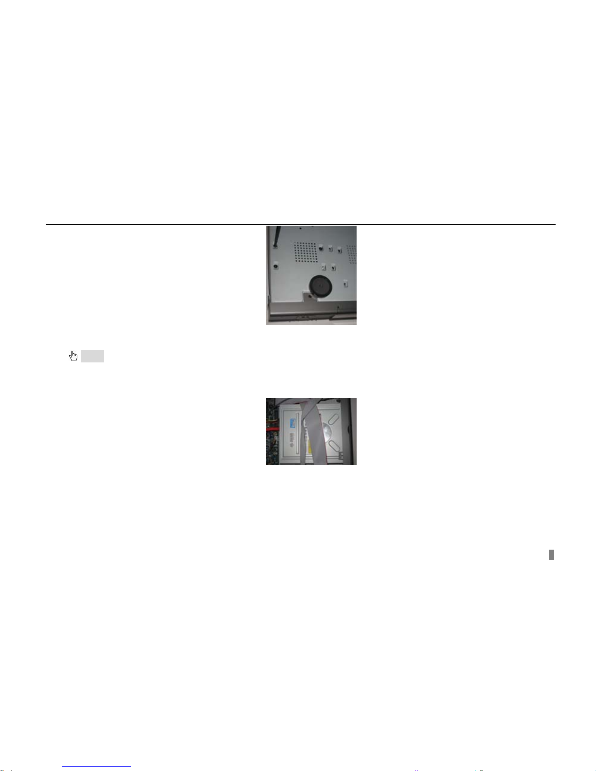
2.1.1 Install Hard Drive
Notice: 1. Support two SATA hard drive. Please use the hard drive the manufacturers recommend specially for security and safe field.
2. Please calculate HDD capacity according to the recording setting. Please refer to “Appendix B Calculate Recording Capacity”.
STEP1 Unscrew and Open the top cover
STEP2 Connect the power and data cables. Place the HDD onto the bottom case as below.
Fig 2.1 Connect HDD
STEP3 Screw the HDD as below.
Note: For the convenience to install, please connect the power and data cables firstly, and then screw to fix.
Digital Video Recorder User Manual
5
Fig 2.2 Screw HDD
2.1.2 Install DVD Writer
Notice: 1. The writers must be the compatible devices we recommend. Please refer to “Appendix C Compatible Devices”
2. This device is only for backup
STEP1 Unscrew and Open the top cover
STEP2 Connect the power and data cables. Place the DVD writer onto the bottom case as below.
Fig 2.3 Connect the DVD Writer
STEP3 Screw the DVD writer as below.
Digital Video Recorder User Manual
6
Fig 2.4 Screw the Writer
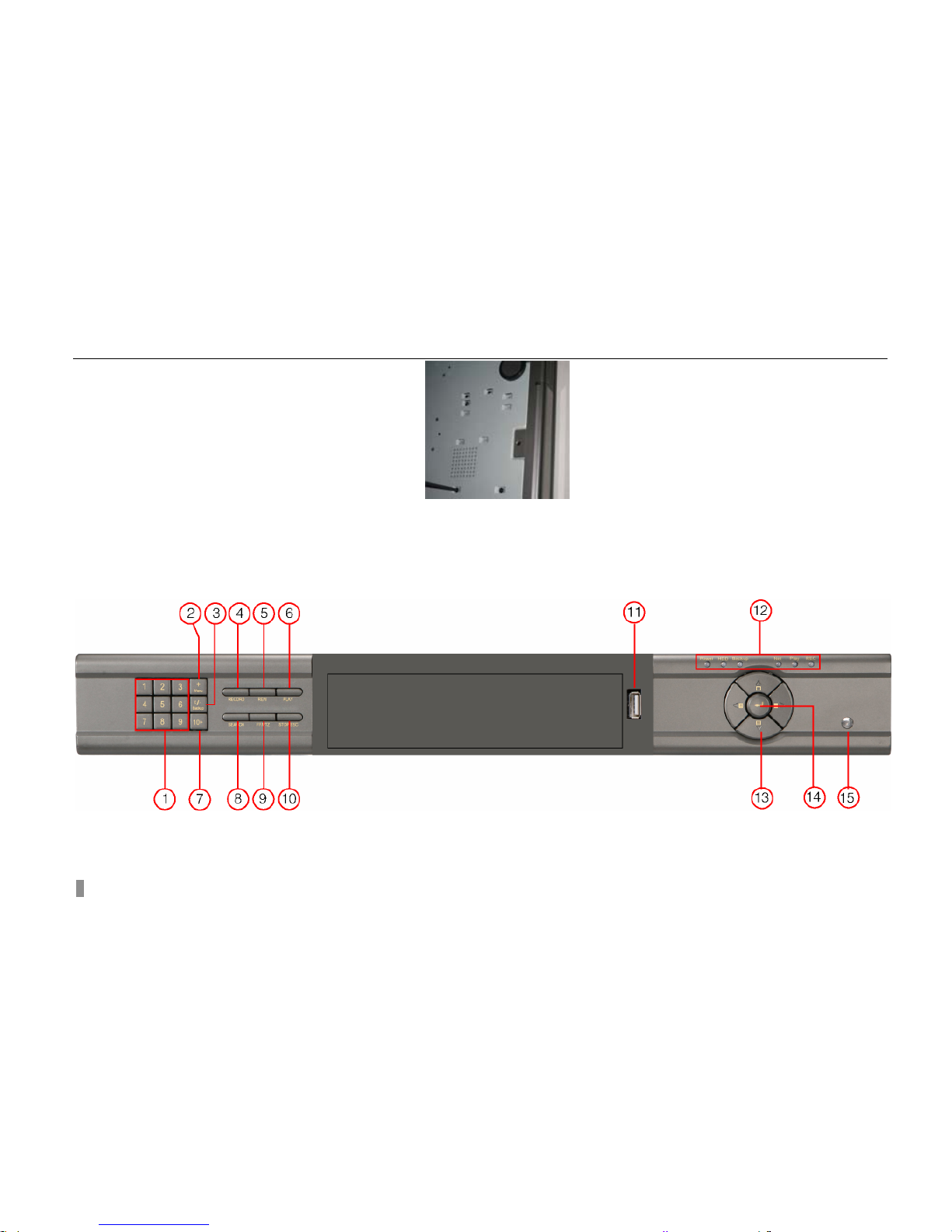
2.2 Front Panel Instruction
The Front Panel interface is shown as
Fig 2.5 Front Panel
.
Fig 2.5 Front Panel for 8-channel and 16-channel DVR

Digital Video Recorder User Manual
7
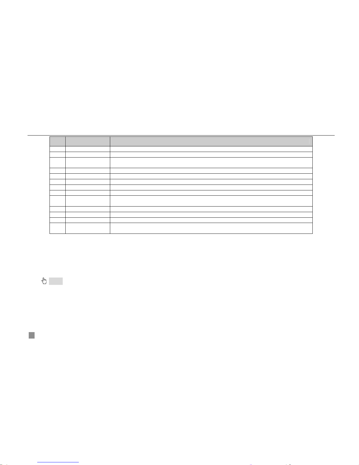
Item Name Function
1 Digital button Input digitals or choose camera
2 +/Menu button
1. Increase the value in setup
2. Enter menu in live
3 -/Backup
1. Decrease the value in setup
2. Enter backup mode in live
4 RECORD Record manually
5 REW Rewind
6 PLAY Enter playback interface
7 10+ Choose channel 10 above with other digitals 0-9, and double-click is 10.
8 SEARCH Enter search mode
9 FF/PTZ
1. Fast forward
2. Enter PTZ mode in live
10 STOP/ESC
1. Quit playback mode
2. Exit the current interface or status
11 USB port To connect external USB devices like USB flash, USB HDD for backup or update firmware
12 Indicator Working indicators of power, HDD, network, etc
13
Direction/Multi-screen
button
1. Direction buttons. Move cursor in setup or pan/title PTZ
2. Change screen display like single, 4, 9 and 16 screens
14 Enter button To confirm the choice or setup
15 IR Receiver For remote controller
Tab 2.1 Definition of Front Panel Buttons
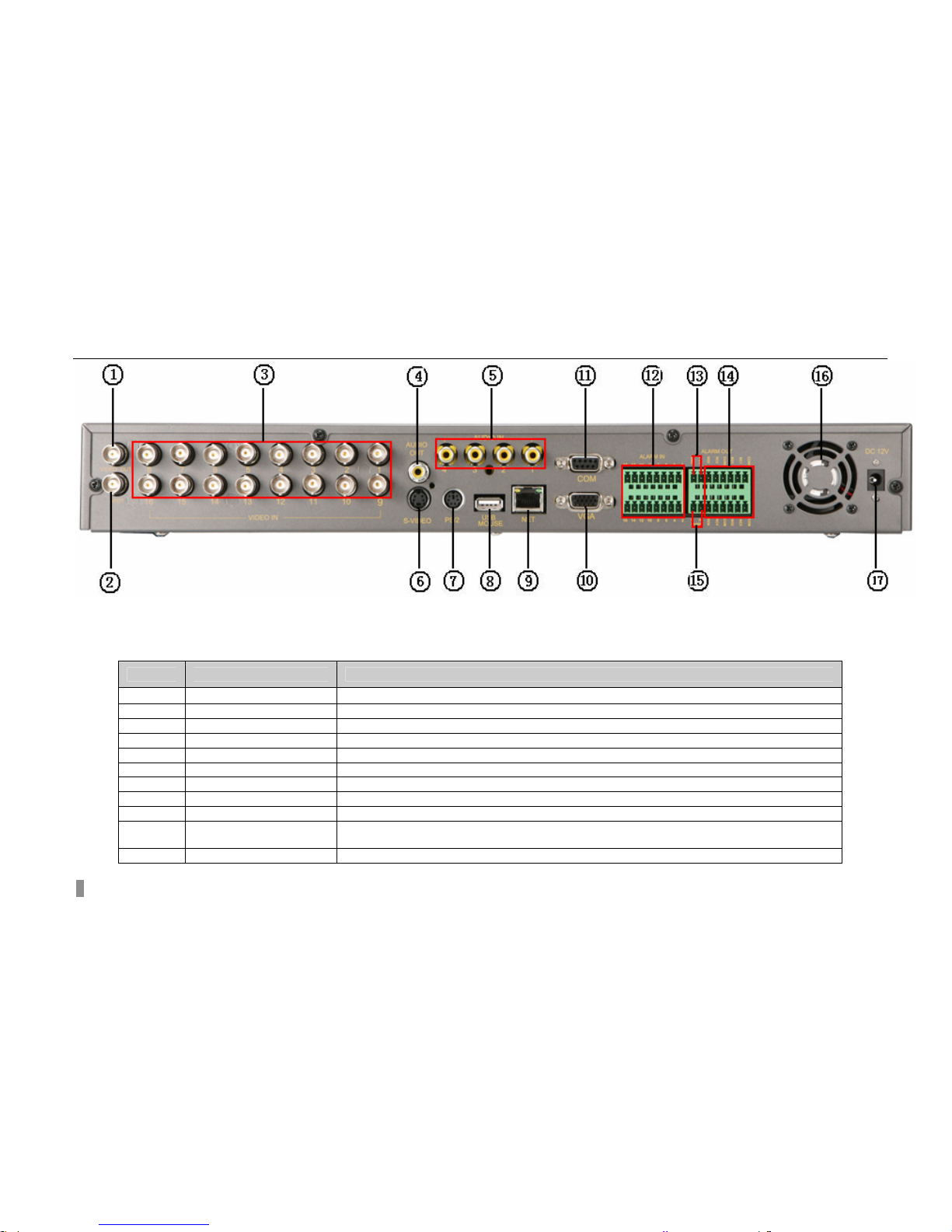
2.3 Rear Panel Instruction
2.3.1 Rear Panel Interface
The rear Panel interface is shown as
Fig 2.6 Rear Panel.
Digital Video Recorder User Manual
8
Fig 2.6 Rear Panel for 16-channel DVR
Item Name Description
1 VIDEO OUT Connect to monitor
2 SPOT Connect to monitor as an AUX output channel by channel. only video display, no menu show
3 VIDEO IN 16ch Video input
4 AUDIO OUT Audio output, connect to the sound box
5 AUDIO IN Audio input, connect to MIC or other audio capture devices
6 S-VIDEO S-Video output, connect to monitor
7 PS/2 port Connect to PS/2 mouse
8 USB port Only for USB mouse
9 RJ45 port Connected to internet
10 VGA port VGA output, connect to monitor
11 COM port For debug
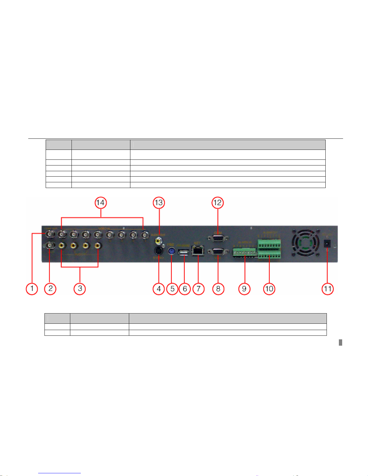
Digital Video Recorder User Manual
9
Item Name Description
12 ALARM IN Connect to external sensor1-16. Please refer to 2.3.2 Install Sensor &Alarm
13 +5V and GND +5 Voltage and Ground
14 ALARM OUT Relay output1-4. Connect to external alarm. Please refer to 2.3.2 Install Sensor &Alarm
15 RS485 Connected to speed domes
16 FAN For cooling the device
17 POWER INPUT DC 12V
Tab 2.2 Definition of Rear Interface
Fig 2.7 Rear Panel for 8-channel
Item Name Description
1 VIDEO OUT Connect to monitor
2 SPOT OUT Connect to monitor as an AUX output channel by channel. only video display, no menu show

Digital Video Recorder User Manual
10
Item Name Description
3 AUDIO IN 8-channel Video input
4 S-VIDEO S-Video output, connect to monitor
5 PS/2 port Connect to PS/2 mouse
5 AUDIO OUT Audio output, connect to the sound box
6 USB MOUSE port Only for USB mouse
7 RJ45 port Connected to internet
8 VGA port VGA output, connect to monitor
9 ALARM IN Connect to external sensor 1-8. Please refer to 2.3.2 Install Sensor &Alarm
10 ALARM OUT Relay output 1-4. Connect to external alarm. Please refer to 2.3.2 Install Sensor &Alarm
11 POWER INPUT DC 12V
12 COM port For debug
13 AUDIO OUT Audio output, connect to the sound box
14 VIDEO IN Connect camera
Tab 2.3 Definition of Rear Interface
Notice: The resolution of VGA output is 800*600/60Hz. If connected through VGA port, please assure your display supports the display
mode.(For most of LCD screens, they can adapt to it automatically without adjustment manually)
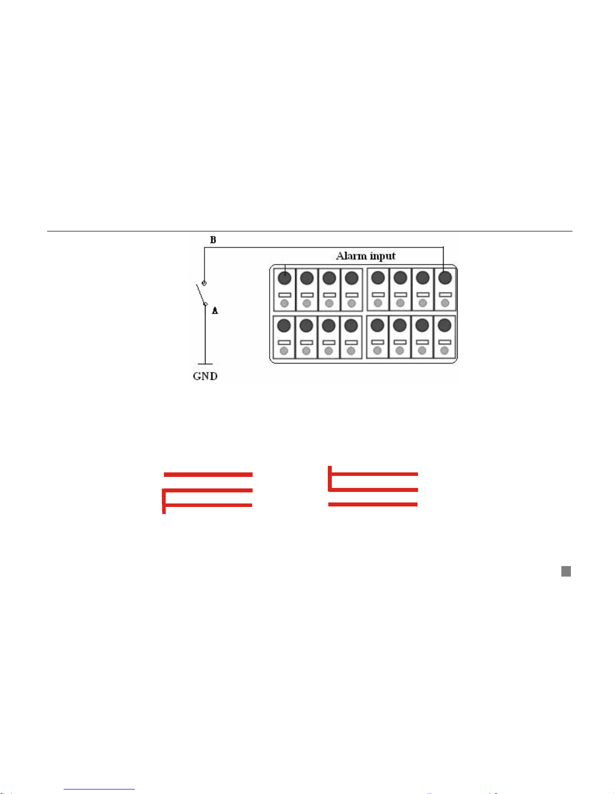
2.3.2 Install Sensor &Alarm
The DVR has 16 channel alarm input and 4-channel alarm output.
Alarm Input:
The alarm input is triggered by electric level (High: 5V, Low: 0V). Users can connect external sensors, like gas detector,
smoke detector and infrared detector. Once the DVR detects that the electric level meets the setting users make, it will
trigger DVR to record or alarm out.
For example, a sensor is connected to alarm input1. If the sensor gives relay out(switch on/off), user need set the sensor
according to the switch status at alarm. If the switch is open at alarm, users need set SENSOR TYPE as NC(Normal
Close),. Cable A and B will be disconnected once the sensor detect event. It will detect +5V (high level) to sensor1 when
events happen. DVR is triggered. it will record and output alarm.
Digital Video Recorder User Manual
11
Fig 2.8 Alarm status
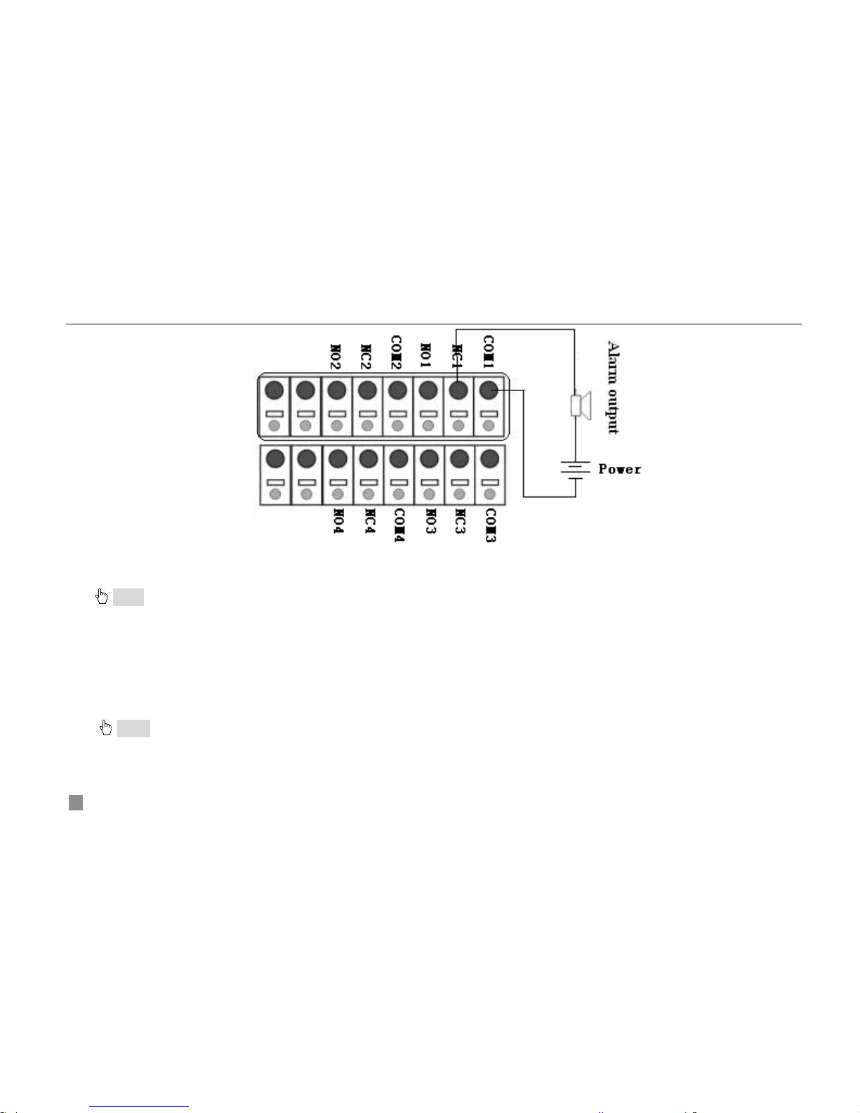
Alarm output:
The DVR has 4-channel relay alarm output, which just give on/off signal to external alarm. The status of these pin are
illustrated as 2.8.
NO
..
COM
NC
..
NO
..
COM
NC
..
Before alarm
After alarm
Fig 2.9 Relay Output Status
Users need connect their alarm according to the NO or NC type of the alarm. One connection example as Fig 2.1
Digital Video Recorder User Manual
12
Fig 2.10 Alarm Output Connection
Notice: The power in series must be 277VAC/10A or 30VDC/10A or below
2.4 Remote Controller
It uses two AAA size batteries and works after loading batteries as below
STEP1 Open the battery cover of the Remote Controller
STEP2 Place batteries. Please take care the poles (+ and -)
STEP3 Replace the battery cover
Notice: Frequently defect checking as following
1. Check batteries poles
2. Check the remaining charge in the batteries
3. Check IR controller sensor is mask
Digital Video Recorder User Manual
13
If it doesn't still work, Please change a new remote controller to try, or contact your dealers
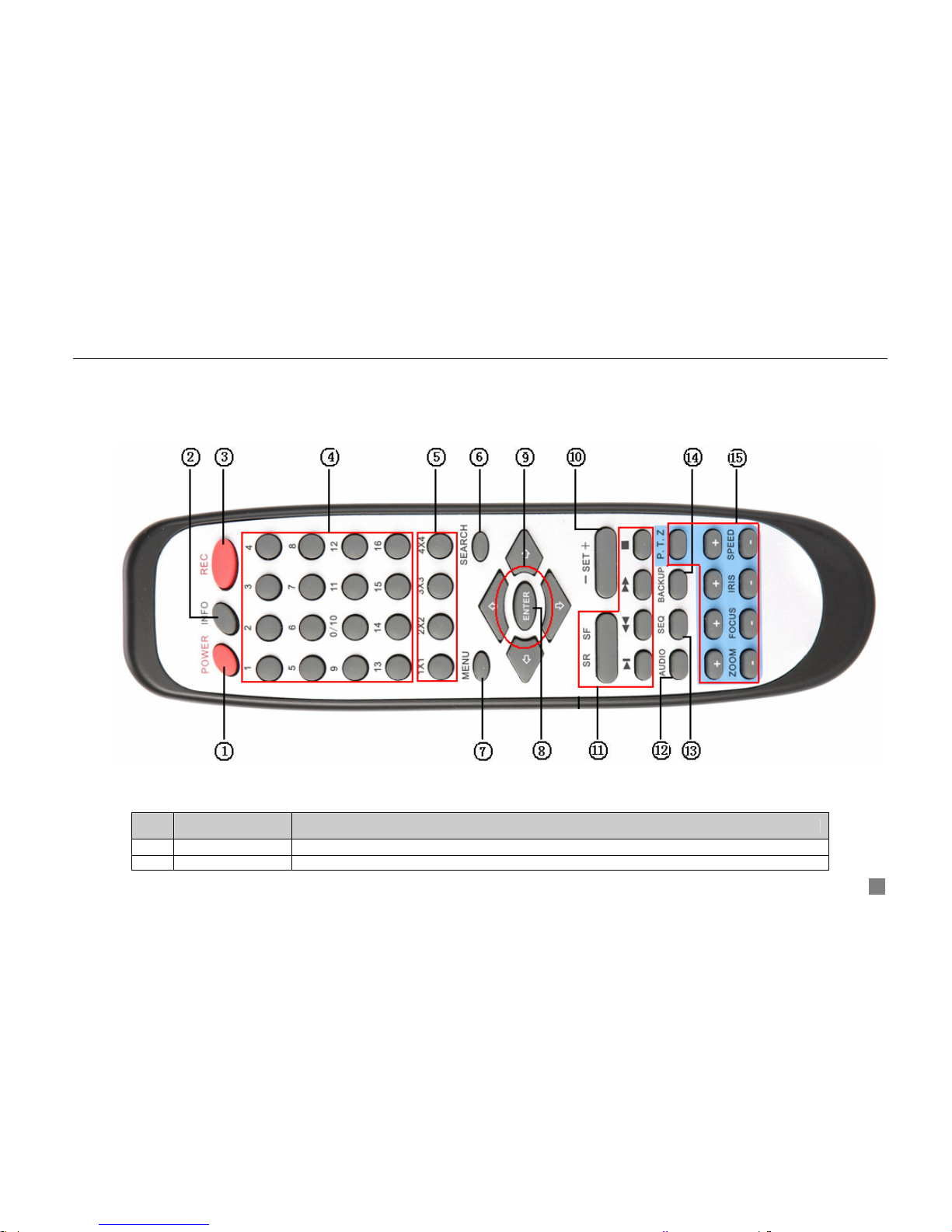
The interface of remote controller is shown in
Fig 2.11 Remote Controller
Fig 2.11 Remote Controller
Item Name Function
1 Power Button Soft switch off to stop firmware running. Do it before power off.
2 INFOR Button Get information about the DVR like firmware version, HDD information
Digital Video Recorder User Manual
14
Item Name Function
3 REC Button To record manually
4 Digital Button Input digital or choose camera
5
Multi Screen
Button
To choose multi screen display mode
6 SEARCH Button To enter search mode
7 MENU Button To enter menu
8 ENTER Button To confirm the choice or setup
9 Direction Button Move cursor in setup or pan/title PTZ
10 +/- Button To increase or decrease the value in setup
11
Playback Control
Button
To control playback. Fast forward/rewind/stop/single frame play
12 AUDIO Button To enable audio output in live mode
13 Auto Dwell Button To enter auto dwell mode
14 BACKUP Button To enter backup mode
15
PTZ Control
Button
To control PTZ camera. Move camera/ZOOM/FOCUS/IRIS/SPEED control
Tab 2.4 Definition of Remote Controller
2.5 Control with Mouse
2.5.1 Connect Mouse
It supports PS/2 or USB mouse through the ports on the rear panel, please refer to
Fig 2.11 Remote Controller.
Notice: If mouse is not detected or doesn't work, check as below
1. Unplug/re-plug several times
2. Power off/on several times
3. Change a mouse to try
2.5.2 Use Mouse
The structure of the main menu is shown in
Fig 2.11 Remote Controller
Digital Video Recorder User Manual
15
In live:
Click left button on one camera to be full screen display. Click again to return to the previous screen display.
Click right button to show the control bar at the bottom of the screen as
Fig 2.11 Remote Controller. Here are all control and setup. Click right mouse again to hide the control bar.
In setup:
Click left button to enter. Click right button to cancel setup, or return to the previous.
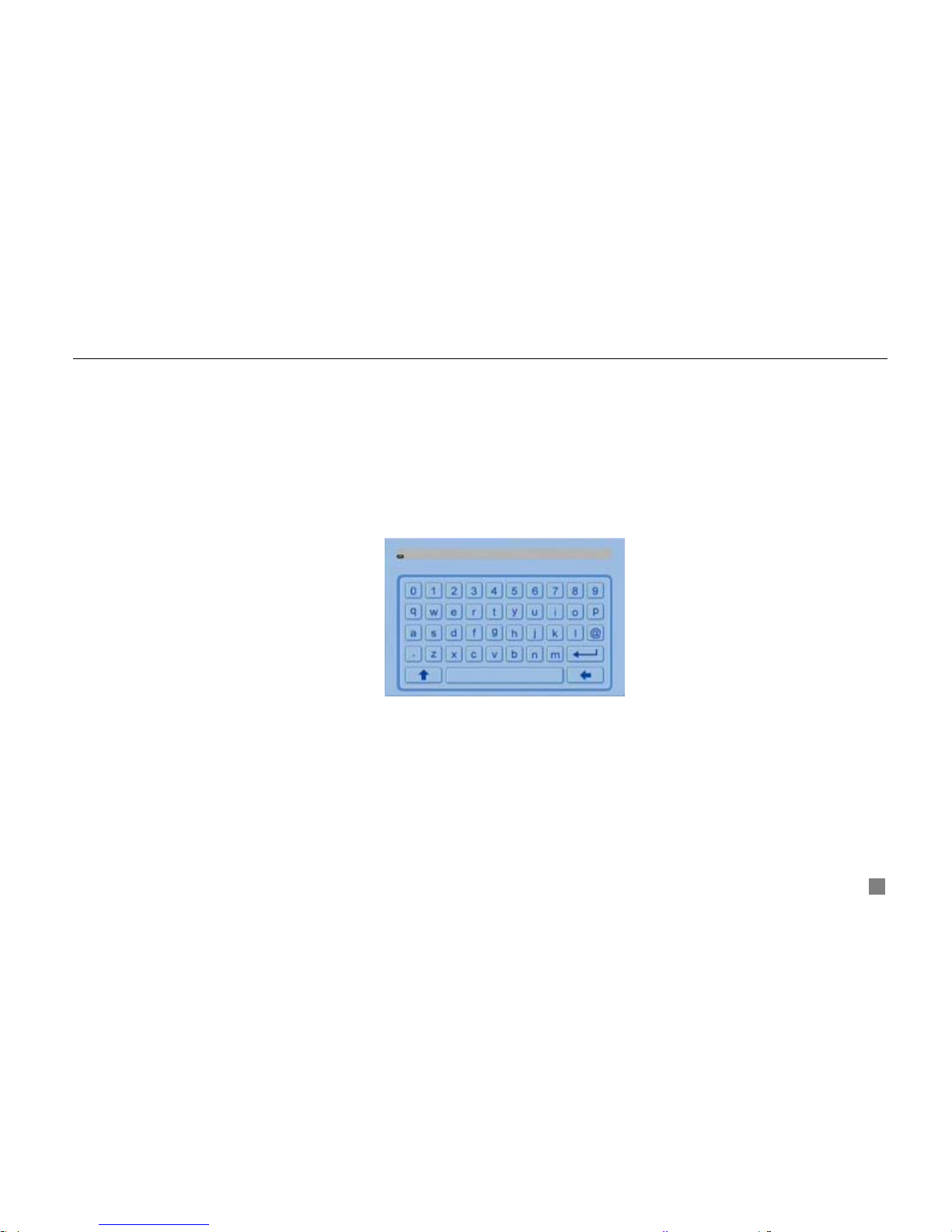
If want to input the value, move cursor to the blank and click. A input window will appear as
Fig 2.11 Remote Controller. It supports digitals, letters and symbols input.
Fig 2.12 Input Window
Users can change some value by the wheel, such as time. Move cursor onto the value, and roll the wheel when the
value blinks.
It supports mouse drag. I.e. Set motion detection area: click customized, hold left button and drag to set motion
detection area. Set schedule: hold left button and drag to set schedule time
In playback:
Click left button to choose the options. Click right button to return to searching mode.
In backup:

Digital Video Recorder User Manual
16
Click left button to choose the options. Click right button to return to live.
In PTZ control:
Click left button to choose the buttons to control the PTZ. Click right button to return to searching mode.
Notice: Mouse is the default tool in all the operation below unless Exceptional indication.

Digital Video Recorder User Manual
17
CHAPTER 3 Basic Function Instruction
3.1 Power On/Off
Notice: Before you power on the unit, please mak e s ure al l the co nn ection is good.
Connect with the source power, switch on POWER button, and the system will be loaded. The screen show as Fig 3.1
System Loading
Fig 3.1 System Loading
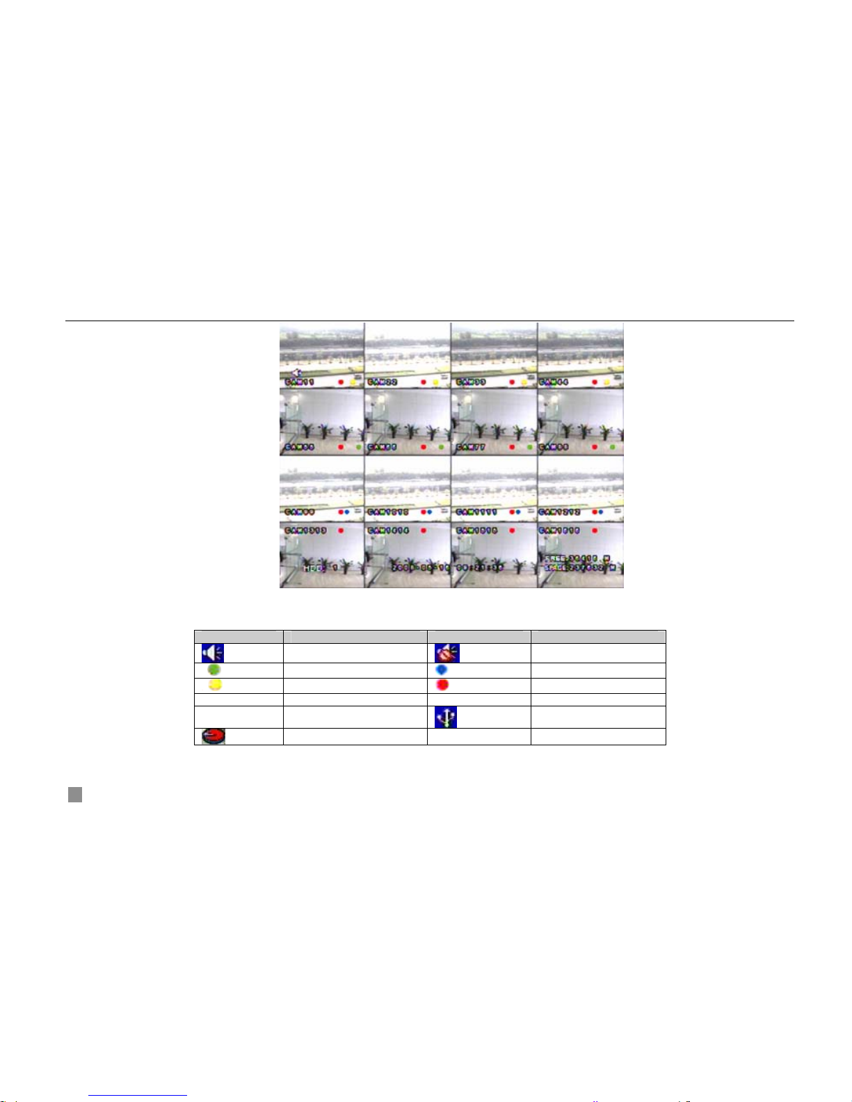
After that, it will enter live in 16 screens. The meaning of letters or symbols on screen is as the form below.
Digital Video Recorder User Manual
18
Fig 3.2 Preview
Symbol Meaning Symbol Meaning
Enable audio in live
Disable audio in live
(green)
Manual record
(blue)
Timer record
(yellow)
Motion detection record
(red)
Alarm record
HDD Current working HDD Space Size of current HDD
Free Free space of current
USB devices connected
HDD full
Tab 3.1 Symbols in Live
Power off safely, please follow the below. Users can close the unit by remote controller, front panel and mouse.

Digital Video Recorder User Manual
19
By remote controller:
STEP1 Press POWER button, the screen below will appear.
Fig 3.3 Shut down
STEP2 Choose OK to enter. The unit will power off automatically after a while
STEP3 Disconnect the power
By front panel or mouse:
STEP1 Press ENTER button or click right mouse to show menu bar, referring to Fig 4.1 Control Bar.
STEP2 Click Shut down button, referring to Fig 3.3 Shut down
STEP3 Click OK to enter on the pop-up window. The unit will power off automatically after a while
STEP4 Disconnect the power
3.2 Login &User Management
Users can logout and login the DVR system. Users cannot do any other operations except changing the multi screen
display once logout. It is in logout once it starts or restarts.
Login:
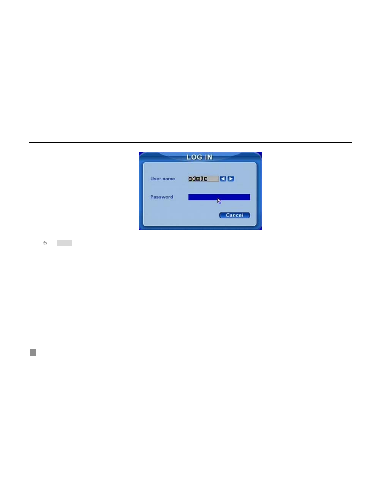
If it is in logout, please press right mouse to show the control bar. Press Login, Search or System etc. A login window will
Digital Video Recorder User Manual
20
appear, asking for ID and password as Fig 3.4 Login.
Fig 3.4 Login
Notice: The default is admin and 123456.
Change password:
Every one can change his own password.
STEP1 In login state, click Log in/out on the control bar. A window will appear with two options. One is for logout,
another for password modification. Click Password, the window will appear as Fig 3.5 Change Password.
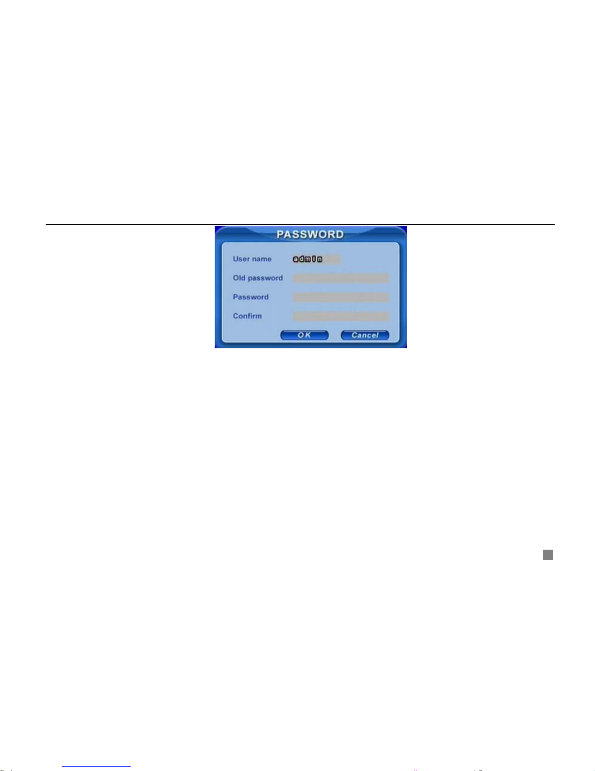
Digital Video Recorder User Manual
21
Fig 3.5 Change Password
STEP2 Input the old password. Then input new password 2 times.
STEP3 Press OK button to change.
NOTE: If you have lost or forgotten your password contact Swann Technical support for assistance.
Add &Delete users:
This unit has a default administrator and two user groups, advance and normal user. It supports 1 administrator and 15
users totally. Administrator can add or delete other users, and change their group level. Administrator cannot be added or
deleted.
Press right mouse to show the control bar. Enter Menu---->System.
STEP1 Enter USER configuration. Click Add button, please see Fig 3.6 Add User.
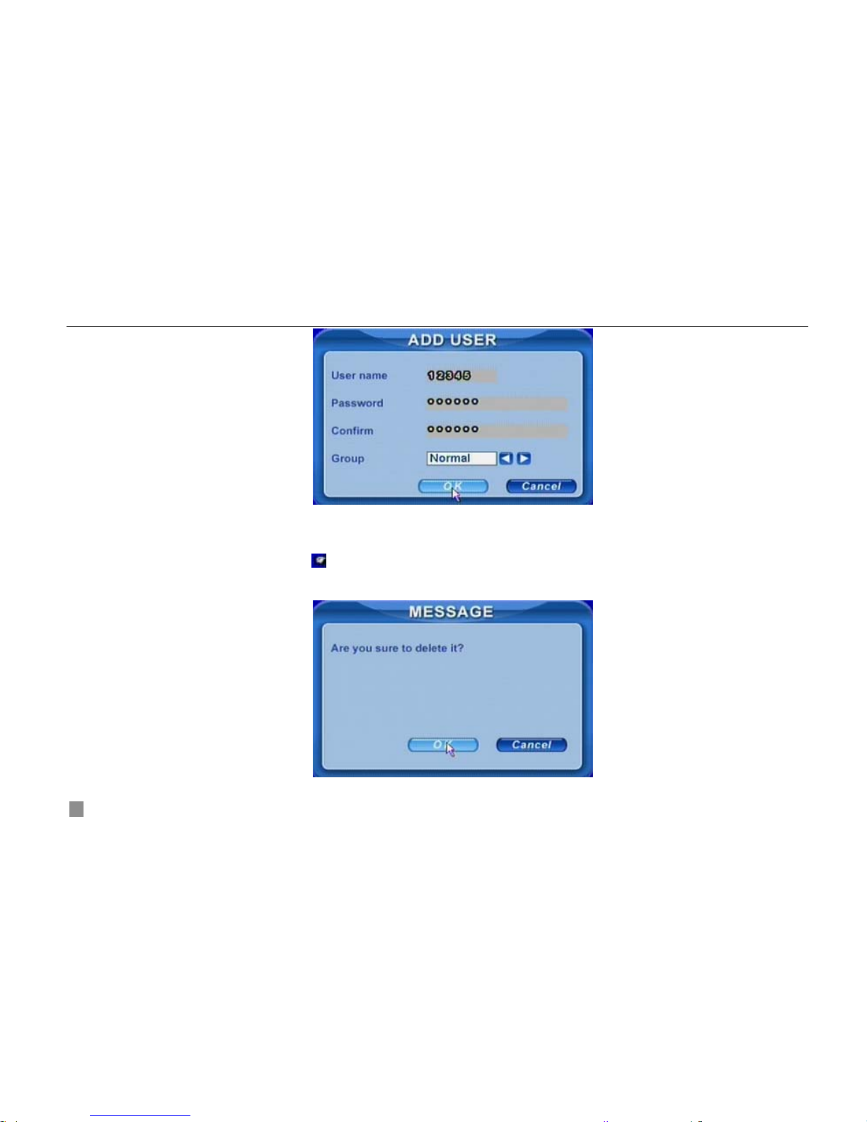
Digital Video Recorder User Manual
22
Fig 3.6 Add User
STEP2 Input user name and password. Choose the user group.
STEP3 Click OK button to add a new user
STEP4 Choose a user, a symbol
will display at the end of the user information. Click Authority button to change the
group level.
STEP5 Press Delete button to delete the user. A security window will appear as below.

Digital Video Recorder User Manual
23
STEP6 Click OK button to delete the user
Notice: illumination of users’ rights
Administrator: have all rights to do every thing.
Advance: do others except entering USER to manage users
Normal: do others except entering SYSTEM to change the settings.
The user name and password are the combination of digitals, letters, or symbols. The number of characters must be one or above.
3.3 Recording
3.3.1 Record Setup
Users need install and format a HDD, and set all the recording parameters before recording. It has four recording modes.
Users can enable them simultaneously. However, they have different priorities as below.
Motion detection recording > Sensor recording > Manual recording > Timer recording
Press right mouse to show the control bar, referring to Fig 4.1 Control Bar. Enter Menu---->System.
STEP1 Enter RECORD configuration, referring to Fig 3.7 Record Setup. Select cameras.
 Loading...