

Swann DVR4-5600 Operating Instructions Manual

Swann Technical Support
4 Channel H.264 Digital Video Recorde
All Countries E-mail: tech@swannsecurity.com
Telephone Helpdesk
USA toll free
1-800-627-2799
(Su, 2pm-10pm US PT)
(M-Th, 6am-10pm US PT)
(F 6am-2pm US PT)
USA Exchange & Repairs
1-800-627-2799 (Option 1)
(M-F, 9am-5pm US PT)
AUSTRALIA toll free
1300 138 324
(M 9am-5pm AUS ET)
(Tu-F 1am-5pm AUS ET)
(Sa 1am-9am AUS ET)
NEW ZEALAND toll free
0800 479 266
UK
0203 027 0979
Advanced security made easy
4 Channel H.264 Digital Video Recorder
™
plug&playsecurity
™
DVR4-5600™
See http://www.worldtimeserver.com for information on time zones and the
current time in Melbourne, Australia compared to your local time.
© Swann Communications 2010
Operating Instructions
SW349-9AO
www.swannsecurity.com
M9AO070510E

Before You Begin
FCC Verifi cation:
NOTE: This equipment has been tested and found to comply with the limits
for Class B digital device, pursuant to part 15 of the FCC Rules. These limits
are designed to provide reasonable protection against harmful interference in
a residential installation. This equipment generates, uses and can radiate radio
frequency energy and, if not installed and used in accordance with the instructions,
may cause harmful interference to radio or television reception, which can be
determined by turning the equipment off and on, the user is encouraged to try to
correct the interference by one or more of the following measures:
· Reorient or relocate the receiving antenna
· Increase the separation between the equipment and the receiver
· Connect the equipment into an outlet on a circuit different from that to which
the receiver is connected
· Consult the dealer or an experienced radio/TV technician for help
Warranty Information
Swann Communications USA Inc.
12636 Clark Street
Santa Fe Springs CA 90670
USA
Limited Warranty Terms & Conditions
Swann Communications warrants this product against defects in workmanship
and material for a period of one (1) year from it’s original purchase date. You must
present your receipt as proof of date of purchase for warranty validation. Any unit
Swann Communications
Unit 13, 331 Ingles Street,
Citilink Estate,
Port Melbourne Vic 3207
Swann Communications LTD.
Stag Gates House
63/64 The Avenue
SO171XS
United Kingdom
These devices comply with part 15 of the FCC Rules. Operation is subject to the
following two conditions:
(1) These devices may not cause harmful interference, and
(2) These devices must accept any interference received, including interference
that may cause undesired operation.
IMPORTANT NOTE: Prohibition against eavesdropping
Except for the operations of law enforcement offi cers conducted under lawful
authority, no person shall use, either directly or indirectly, a device operated
pursuant to the provisions of this Part for the purpose of overhearing or recording
the private conversations of others unless such use is authorized by all of the
parties engaging in the conversation.
WARNING: Modifi cations not approved by the party responsible for compliance
could void user’s authority to operate the equipment.
IMPORTANT SAFETY INSTRUCTIONS:
· Make sure product is fi xed correctly and stable if fastened in place
· Do not operate if wires and terminals are exposed
· Do not cover vents on the side or back of the DVR and allow adequate space for
ventilation
which proves defective during the stated period will be repaired without charge
for parts or labour or replaced at the sole discretion of Swann. The end user is
responsible for all freight charges incurred to send the product to Swann’s repair
centres. The end user is responsible for all shipping costs incurred when shipping
from and to any country other than the country of origin.
The warranty does not cover any incidental, accidental or consequential damages
arising from the use of or the inability to use this product. Any costs associated with
the fi tting or removal of this product by a tradesman or other person or any other
costs associated with its use are the responsibility of the end user. This warranty
applies to the original purchaser of the product only and is not transferable to any
third party. Unauthorized end user or third party modifi cations to any component
or evidence of misuse or abuse of the device will render all warranties void.
By law some countries do not allow limitations on certain exclusions in this warranty.
Where applicable by local laws, regulations and legal rights will take precedence.
2
67

Notes
_________________________________________________________________
_________________________________________________________________
_
_
_
_
_________________________________________________________________
_________________________________________________________________
_________________________________________________________________
_
_
_
_
_________________________________________________________________
_________________________________________________________________
_
_
_
_
_________________________________________________________________
_________________________________________________________________
_________________________________________________________________
_
_
_
_
_________________________________________________________________
_________________________________________________________________
_
_
_
_
_________________________________________________________________
_________________________________________________________________
_________________________________________________________________
_
_
_
_
_________________________________________________________________
_________________________________________________________________
_
_
_
_
_________________________________________________________________
_________________________________________________________________
_________________________________________________________________
_
_
_
_
_________________________________________________________________
_________________________________________________________________
_________________________________________________________________
_
_
_
_
_________________________________________________________________
_________________________________________________________________
_
_
_
_
_________________________________________________________________
_________________________________________________________________
_
_
_
_
_
_
_________________________________________________________________
_________________________________________________________________
Table of Contents
____________________________________________________________________
____________________________________________________________________
____________________________________________________________________
____________________________________________________________________
____________________________________________________________________
____________________________________________________________________
____________________________________________________________________
____________________________________________________________________
____________________________________________________________________
____________________________________________________________________
____________________________________________________________________
____________________________________________________________________
____________________________________________________________________
____________________________________________________________________
____________________________________________________________________
____________________________________________________________________
____________________________________________________________________
____________________________________________________________________
____________________________________________________________________
____________________________________________________________________
____________________________________________________________________
____________________________________________________________________
____________________________________________________________________
____________________________________________________________________
____________________________________________________________________
____________________________________________________________________
____________________________________________________________________
____________________________________________________________________
____________________________________________________________________
____________________________________________________________________
____________________________________________________________________
____________________________________________________________________
____________________________________________________________________
____________________________________________________________________
____________________________________________________________________
____________________________________________________________________
____________________________________________________________________
____________________________________________________________________
____________________________________________________________________
____________________________________________________________________
____________________________________________________________________
____________________________________________________________________
66
Before You Begin
Table of Contents
_______________________________________________________________
Package Contents
_______________________________________________________________
Read Before Installation
Overview
Important Information
Layout
_______________________________________________________________
Layout of the Connection Panel
_______________________________________________________________
Layout of the Remote Control
Connection Guide
Navigating the Menus
_______________________________________________________________
Starting the DVR
_______________________________________________________________
The Main Menu
The Camera (Display Setup) Menu
The Record Setup Menu
The Recording Schedule
_______________________________________________________________
The Network Confi guration Menu
_______________________________________________________________
The Video Search Menu
The File List & USB Backup
The Playback Interface
_______________________________________________________________
Playing Backed Up Footage on a PC
_______________________________________________________________
The Device Management Menu
The HDD (Hard Drive) Management Screen
The PTZ (Pan, Tilt, Zoom) Setup Menu
The Alarm Menu
_______________________________________________________________
Auto Email Setup
_______________________________________________________________
The Mobile Devices Menu
The Motion Detection Menu
Motion Detection Confi guration
______________________________________________________________
The System Setup Menu
_______________________________________________________________
The Time Setup Menu
The Password Setup Menu
The Video Setup Menu
The Language and Info Menus
_______________________________________________________________
The System Maintenance Menu
_______________________________________________________________
PTZ Controls
Requirements for Remote Access
Setting Up Remote Access
Remote Access via Internet Explorer
_______________________________________________________________
Remote Access from a Mobile Device
_______________________________________________________________
NetViewer - About the Software
NetViewer - Installation Guide
NetViewer -Starting the Software
_______________________________________________________________
NetViewer -The Main Interface
_______________________________________________________________
NetViewer - The Replay Interface
NetViewer - Setup
Installing/Changing the HDD
_______________________________________________________________
Troubleshooting
_______________________________________________________________
Technical Specifi cations
_______________________________________________________________
Notes
Warranty Information
Technical Support
2
3
4
5
6
7
8
9
10
11
12 - 13
14
15
16 - 17
18 - 19
20 - 21
22 - 23
24
25
26 - 27
28 - 29
30
31
32
33
34 - 35
36
37
38 - 39
40
41
42
43
44
45
46 - 47
48 - 49
50 - 51
52 - 53
54 - 55
56
57
58
59
60
61 - 62
63
64
65
66
67
68
3
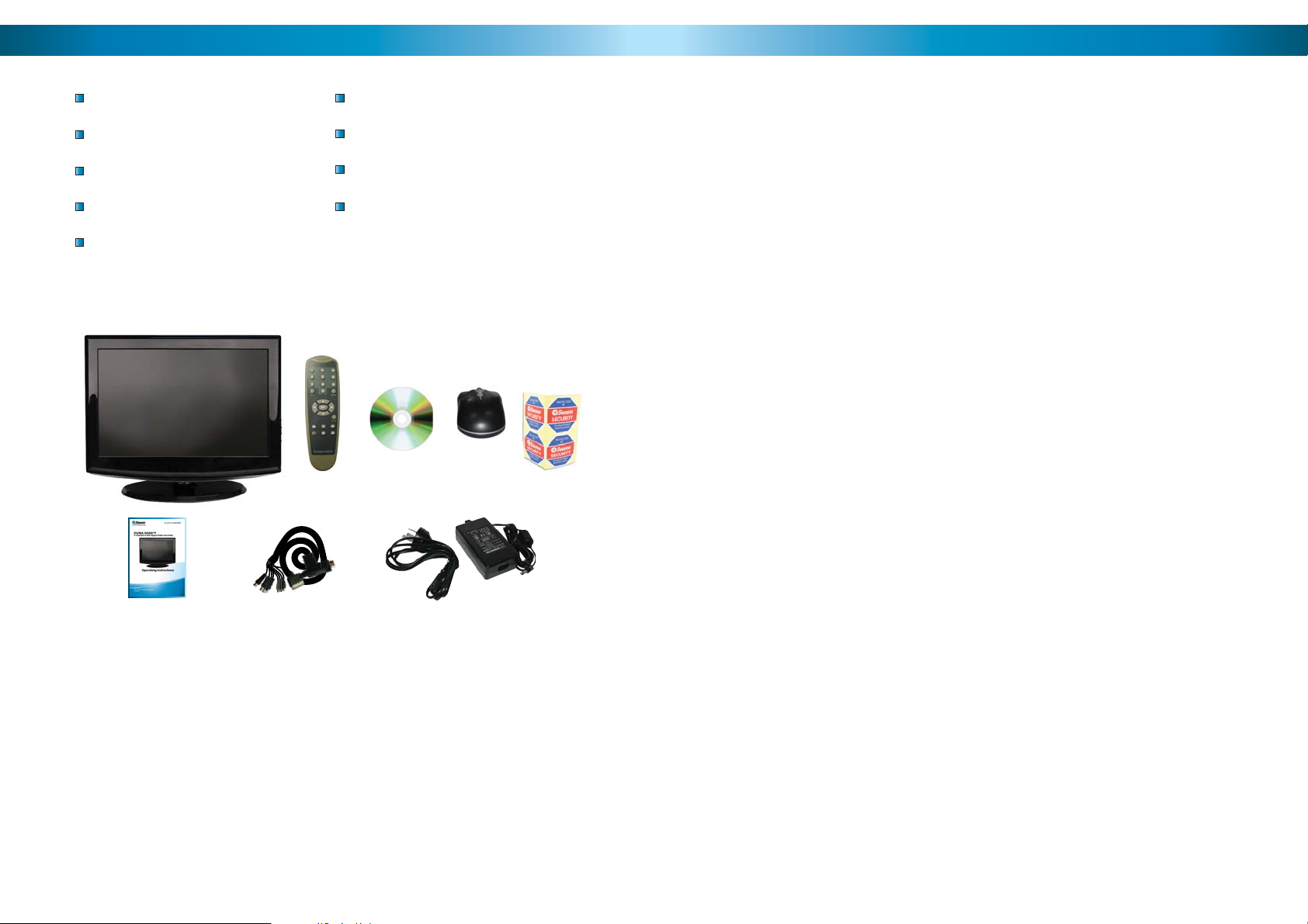
Package Contents
Technical Specifications
DVR4-5600™ Unit
External I/O Cable
Remote Control
Operating Instructions
Easy Setup Guide
Power Adapter with Cable
Software CD
USB Mouse
Security Stickers (4 Pack)
If you are missing any of these
components, contact Swann
Communications for assistance.
DVR4-5600
Video
Video Format PAL or NTSC
Video Inputs 4 x Composite BNC Inputs
Video Outputs
Display Resolution NTSC: 704 x 480, PAL: 704 x 576
Display Frame Rate NTSC: 120fps, PAL: 100fps
Audio
Audio Inputs 4 x RCA Audio Input
Audio Output 2 x RCA Audio Output
Display
Display Type and Size 19” LCD
Maximum Resolution 1280 x 1024
Recording
Compression Format H.264
Recording Resolution NTSC: D1 (704x480), HD1 (704x240), CIF (352x240)
PAL: D1 (704 x 576), HD1 (704 x 288), CIF (352 x 288)
Recording Frame Rate NTSC: 30fps D1, 60fps HD1, 120fps CIF
PAL: 25fps D1, 50fps HD1, 100fps CIF
Recording Modes Manual / Motion / Schedule / Sensor
Multiplex Operation Triplex
HDD Interface SATA
Hard Drive Support Up to 1TB
Network
LAN Connection Yes
Network Interface RJ45
Network Protocol(s) TCP/IP. DDNS
Remote Operation Yes
General
Operating Power DC12V
Dimensions 12.4” x 8.9” x 2.4”
Weight 4.lbs / 2Kg
Backup Method USB to Flash Drive
Mouse Support 1 x USB
Remote Control 1 x InfraRed Controller
Remote Battery Type 2 x AAA
Optional
Additional Feature 4CH Alarm Inputs, 1 CH Output
4
65

Troubleshooting
Problem: My DVR does not switch on.
Solution: Make sure you have plugged in the power supply (12V) to the DVR and
into the wall socket. Carefully check the integrity of the connections. Check the
master switch on the back of the unit. Try another power socket.
Problem: My display is showing “NO HARD DISK” when I press record.
Solution: If you have recently changed the hard drive in your DVR unit make sure
it is plugged in properly; otherwise the hard drive may be faulty. Try connecting
another (working) hard drive to the DVR; if this still doesn’t work then the DVR
maybe faulty. We suggest calling Swann Technical Support - the contact information
is on the rear cover of this booklet.
Problem: I am not getting picture on any of my displays.
Solution: Make sure the cameras are connected properly to the DVR and the
power supply (12V 1A). Check that the cables are not faulty by connecting the
cameras directly to the DVR or to a TV (if you have the proper adapters).
Problem: One of the displays is not showing on my screen.
Solution: Make sure all cameras are set to ON in CAMERA SETUP. Check the
integrity of your cables and connections. Check the power supply to the camera.
Try attaching another channel to the questionable input.
Read Before Installation
IMPORTANT GUIDELINES
Do not expose the DVR to moisture• . Water is the arch-enemy of electrical
components and also poses a high risk of electric shock.
Avoid dusty locations• . Dust has a tendency to build up inside the DVR case,
leading to a high risk of failure or even fi re.
Only install the DVR in a well ventilated space• . The circuitry and hard
drive in the DVR produces a signifi cant amount of heat, and this heat needs
a way out.
Do not open the DVR case• except to install/swap the hard drive inside. There
are no user serviceable parts inside.
Never open the case whilst the DVR is plugged in• , and never turn the
DVR on whilst the case is open.
Use only the supplied power adaptor.• Other adaptors may cause damage
to the DVR or cause a fi re.
Do not cut or modify any cable for any reason.• Doing so will void your
warranty, as well as pose a great risk of fi re or electrical shock.
Problem: I cannot login to my DVR remotely using the NetViewer software or the
Internet Explorer browser.
Solution: Make sure you have confi gured the IP, ActiveX and USER SETUP correctly.
Remember the USER PASSWORD may be different to the ADMIN PASSWORD. The
ADMIN PASSWORD is used to login to the DVR remotely.
Problem: I cannot perform a backup.
Solution: Make sure the DVR is connected to a USB fl ash drive, and that the USB
fl ash drive is formatted to have a FAT32 fi le system.
64
Don’t expose the DVR to sudden bumps or shocks• (for example, being
dropped). The DVR is as robust as possible, but many of the internal components
are quite fragile.
Remember that the DVR is, in all likelihood, going to be left on 24 hours a day, •
7 days a week. Keep this in mind when choosing a location for installation.
IMPORTANT: Do not pull, tug, sharply bend or twist the I/O Cable.
For your convenience, the DVR features an I/O (Input/Output) cable, through which
all your cameras and other devices (such as microphones or PTZ systems) can be
connected.
Like many complex cables used to transmit audio/visual information, it’s made up
of many thin copper cables, each used to carry part of the signal. Rough treatment,
twisting or sharply bending the cable can cause small cracks in the copper cabling,
which will reduce the quality of your images.
5
Overview
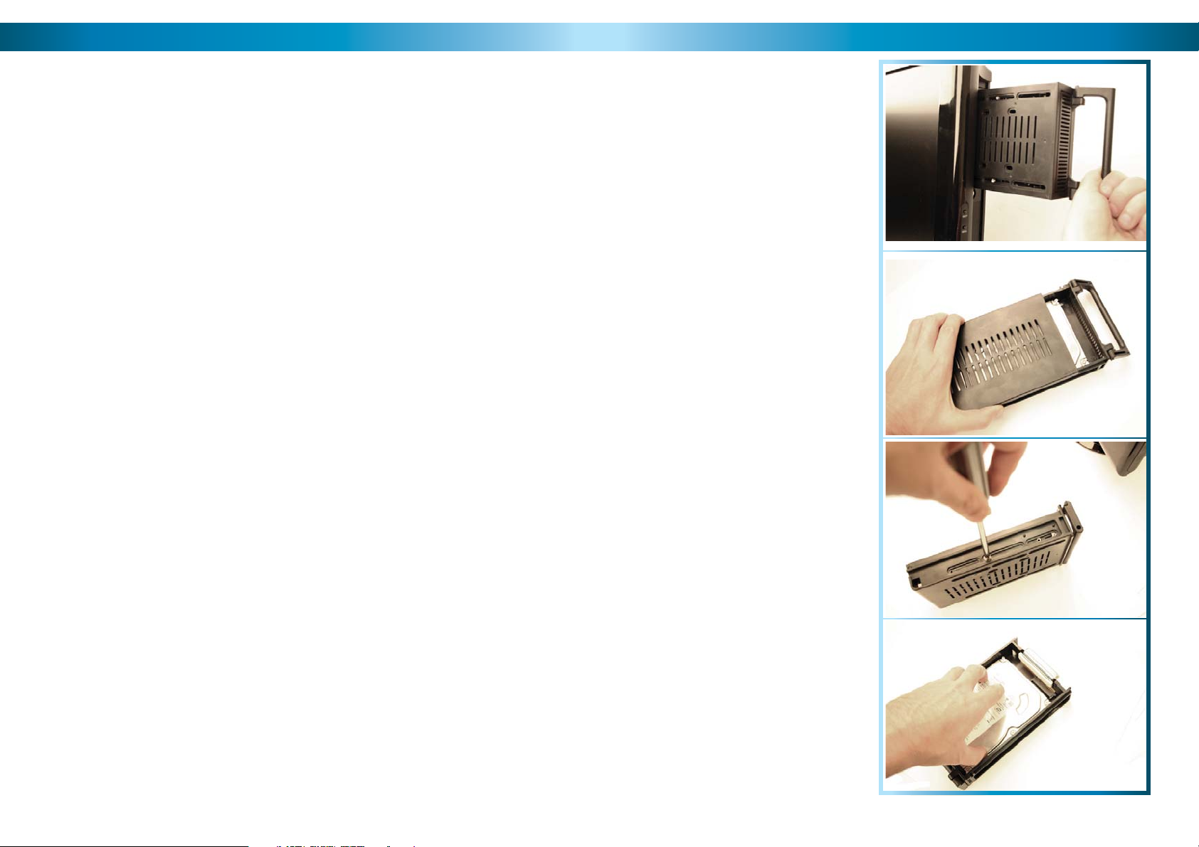
Installing/Changing the HDD
Congratulations on your purchase of the DVR4-5600!
You’ve chosen a versatile, powerful and great value security monitoring and
recording solution for your home or business. Let’s just take a moment to talk
about some of the great features that the DVR4-5600 offers and some of the
things to think about before installing the system.
4 Channel Monitoring and Recording
The DVR4-5600 can monitor and record four channels simultaneously. You can
confi gure the recording modes for the four channels quite independently – for
example, you could have two channels recording on a schedule, one recording
constantly and one armed to record on motion. Or any other combination you can
think of!
Powerful H.264 Compression
The advanced video codec used by the DVR4-5600, called H.264, offers high
quality video fi les at a fraction of the size of older video codecs such as MPEG-2
or similar. Basically, this means you can get store more footage on the DVR’s hard
drive, and that the quality of that footage can be signifi cantly higher than many
older video formats. H.264 has been engineered to provide the highest level of
data compression possible (saving space on your hard drive) whilst maintaining a
high image quality.
Powerful Networking and Remote Access Features
The DVR4-5600 features an Ethernet port, which can be used to connect the
DVR to your home network. With the addition of a high-speed Internet service,
this allows you to remotely access the DVR from any high-speed Internet terminal
on Earth! If that isn’t convenient enough, the DVR also features mobile device
support, allowing you to connect to it from a device running Microsoft Windows
®
Mobile
The DVR4-5600 features an incorporated high defi nition 19” LCD monitor. This
will let you display images from your cameras at a massive resolution of 1280 x
1024, which is about four times the resolution of a standard television! On top
of that, there are fewer plugs and cables to worry about, saving you time, energy
and space.
(version 6 or later) as well as the increasingly popular iPhone.
All-In-One Monitoring Solution
Note: the following instructions are
for installing or changing the hard
drive. If your DVR already has a hard
drive pre-installed, and you don’t want
to change it, disregard these steps.
Ensure the DVR is switched off 1.
and unplugged from mains
power.
Unlock the hard drive keylock, 2.
located immediately below the
hard drive caddy.
Remove the hard drive caddy.3.
To open the hard drive caddy, 4.
slide the top off in the direction
indicated.
Remove the screws holding the 5.
hard drive in the caddy. There
are screws on both sides.
To disconnect the hard drive 6.
from the caddy, slide it forward.
If replacing the hard drive, put the 7.
new hard drive into the caddy. Slide
it towards the back to connect the
SATA and power connections.
Screw in the hard drive to chassis 8.
as in step 5, and replace the top
of the caddy as in step 4.
Insert the caddy onto the DVR.9.
Lock the caddy in place.10.
3
4
5
6
6
63

NetViewer - Setup (continued)
Important Information
Setup: Alarm
Here you’ll fi nd the same options as in
the Alarm Menu in the DVR. These can be
customized in the same manner as they
would be from the menu on the DVR itself.
You can access the motion detection area
defi nition screen from the ALARM menu.
This works in the same manner as the same
screen within the DVR menu. The red squares
indicates the area which will be sensitive to
motion.
Setup: Network
Here you can change the network settings for
the DVR in the same manner as the Network
menu in the DVR itself (see pages 22 & 23 for
more details). You will need to restart both
the DVR and the NetViewer software after
making any dramatic changes. Remember to
update your login information if you change
the ports numbers or IP address of the DVR.
Setup: Setting
DEFAULT PASSWORD INFORMATION
To ensure your privacy, this DVR is password protected.
To unlock the DVR for the fi rst time, the default password is “• 123456”.
To ensure your ongoing privacy, we strongly recommend changing the pass-•
word as soon as possible. Choose something that you’ll remember, but that
others would be unlikely to guess.
If you do manage to lock yourself out of the DVR, you’ll need to contact us •
at the Swann Technical Support Telephone Helpdesk - the number is on the
back cover.
Installation Tips & Tricks
One of the most important things to decide early on is where you’re going to install the DVR. There are several considerations to make, and some of them confl ict
with one another.
Your DVR needs to be located in a central location to allow you maximum •
options when placing your cameras. This is true whether your cameras are
connected via cables or wirelessly - one way, you’ll have to physically install
cabling, and wireless systems still have a limited range.
62
Here you’ll be able to change the settings for
NetViewer. You can alter:
The location on your PC where any •
footage you back up will be stored.
The speed at which your network or •
Internet connection can upload data.
Setting this properly will give you the
best quality video possible without
overloading your connection.
Your passwords. You’ll need to be logged •
in as an administrator (as opposed to a
user) to change this.
You can also turn automatic adjustments •
for daylight savings time on or off.
On the other hand, your DVR should be installed somewhere secure. If the •
DVR is too accessible it could be sabotaged or removed by an intruder.
Ideally, assuming that you wish to use most features this DVR offers, it should •
be installed close to a network access point. There is, however, no problem using a long network cable - a Cat 5e Ethernet cable up to approximately three
hundred feet (about 90m) should work. Different network cable standards will
offer a longer or shorter range.
7
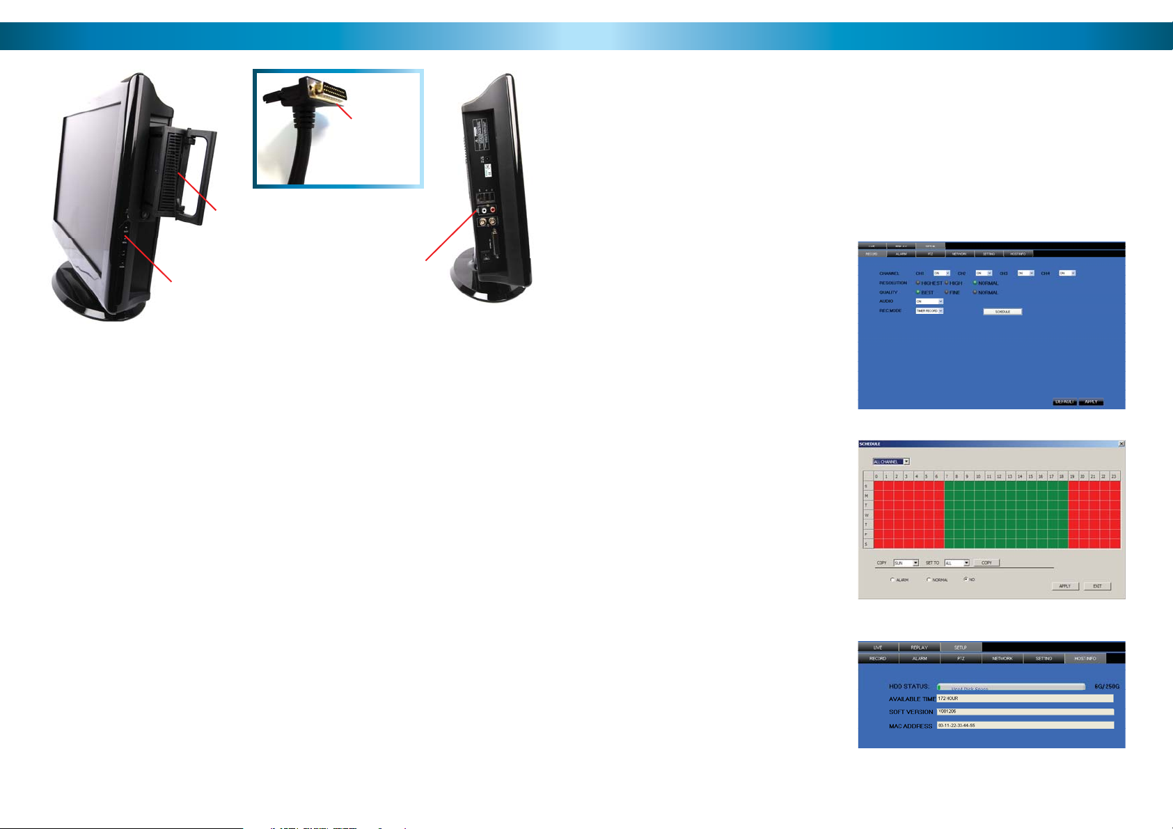
Layout
Hard Drive
in Caddy
Screen ControlsScreen
Hard Drive) The hard drive is where
the DVR will save footage. It’s the same
kind of hard drive you’ll fi nd in most
desktop computers.
Hard Drive Caddy) To protect the
hard drive and to make installation
and transport easier, the hard drive
is mounted in the hard drive caddy.
Note that whilst the caddy offers some
protection, hard drives are still quite
fragile - exercise care at all times!
Screen Controls) The basic controls
for adjusting the settings on the screen.
Note that these controls will ONLY
affect the screen, and not the way that
the DVR records or displays footage.
ON/OFF: Turns the screen (but not the
DVR) on and off. This is useful if you
want to turn off the screen (a good way
to save power) but leave the DVR itself
on.
I/O Cable
Connection Panel
(detail on page 9)
MENU: Opens the Screen Setup Menu.
Here you can alter the Brightness,
Contrast and Saturation settings.
Brightness: Alters how bright the screen
is.
Contrast: Sets the dynamic range - that
is, the difference in intensity between
the darkest black and the whitest
white.
Saturation: How much color there is in
your images.
UP/DOWN: Used to navigate the screen
menu.
I/O Cable) The I/O cable connects to
the External I/O port, located on the
connection panel (see page 9). Do not
twist, bend, pull or tug on this cable!
Connection Panel) The business side
of the DVR. This is where you’ll connect
your cameras and other input devices
(via the I/O cable), as well as where you’ll
fi nd the LAN, USB and audio/video out
connections. Power is connected here.
NetViewer - Setup
In the SETUP you can change the camera record settings. You can turn each channel
on or off, select the recording resolution & quality, turn on or off the audio, select
a record mode and set up the record schedule. Note that you must be logged in
using the ADMINISTRATOR password to be able to change options.
Most of the options that you will fi nd here operate in exactly the same manner
as on your DVR. However, as this software can be used to control a few different
models of DVR, occasionally an option will be displayed which has no effect on your
DVR. Don’t worry about these settings - they won’t interfere with the operation
of your DVR.
Setup: Record
Here you’ll fi nd the same options
as the Record Options menu in the
DVR. You can change the resolution
and quality settings, enable and
disable audio as well as change the
record mode for each channel.
Also accessible from here is the
RECORDING SCHEDULE, which
operates and can be edited in the
same way as the schedule in the
DVR.
Setup: Host Info
Here you’ll be able to fi nd
information about your setup.
You’ll be able to see how much
space remains on your hard drive,
represented in both GB remaining
and hours of footage at your current
record settings. Also, if you need to
know what version of the software
you’re running, this screen will tell
you. Finally, the MAC Address of the
DVR is also found here, if required.
8
61

NetViewer - The Replay Interface
The REPLAY screen allows you to remotely access, playback and backup recordings
from the DVR remotely. When backing up in this manner, the fi le will be saved
directly to the computer you’re accessing the DVR from.
Layout of the Connection Panel
Locate the calender, located in the 1.
upper right hand corner of the
screen.
Click on the date you wish to access 2.
an event from.
Below the calender, there are two 3.
drop down menus.
The fi rst (left) drop-down menu 4.
selects which channel(s) you want.
Playback Controls
Play: Begins playback of the selected event.
Stop: Ends playback.
F.F. (Fast Forward): Increases speed of playback. Press multiple times to further
increase playback speed.
Slow: Reduces the speed of playback. Press multiple times to
further reduce the playback speed.
Next Frame: Moves the video forward by the smallest increment possible,
a single frame.
264 to AVI: Exports the currently selected event as a stand-alone video
fi le that can be played by most computers without dedicated
software. A great backup tool, particularly if you need to
send or share footage with others.
60
The second (right) drop-down 5.
menu chooses the recording mode
you’d like to see events for.
Any event which was recorded on 6.
your selected channel(s) in your
selected recording mode on the
day you’ve selected will be shown
as a chronological list in the small
window located below. Simply
choose the event you want to
playback from this list.
I / O Switch) The master ON (I) / OFF
(O) switch. To quickly turn the DVR on
or off, use this switch.
External I/O) For connecting the I/O
cable. The I/O cable has four video inputs
(VIN1 ~ VIN4), four audio inputs (AIN1 ~
AIN4) and the RS485, alarm and sensor
connections attached. Exercise care whilst
handling this cable (see page 5).
Video Outputs) This sends a composite
video signal out of the DVR. Each of the
two ports can be connected to separate
monitors, or external recording devices.
However, there is no requirement to use
these - the built-in monitor usually does
the job just fi ne.
Audio Outputs) Two mono audio output
channels. These output a standard ‘linelevel’ signal, and can easily be connected
to the audio inputs on a television or
stand-alone audio device.
LAN Port) To connect an Ethernet cable,
allowing the DVR to be connected to
a local area network. This network, in
turn, can be used to give the DVR a
connection to the Internet.
USB Ports) There are two USB ports
on the side of the DVR. The one closest
to the LAN port is for connecting a
standard USB mouse (nothing else will
work in this port). The second USB port
is for attaching a USB storage device,
which can be used to back up footage
from the DVR.
DC 12V) For supplying power to the
DVR. Use only the supplied power
adaptor, and do NOT change or modify
it in any way. Modifi cations to your
power supply radically increases the
risk of electrocution or fi re, and will
immediately void your warranty.
RS485
VIN 1 ~ 4
AIN 1 ~ 4
Audio Inputs
The other end of the I/O cable
VIN 1~4) These are the four Video
INputs (where you’ll connect your
cameras) labeled as per their channel in
the DVR’s interface. Thus, VIN1 will be
shown and recorded in Channel 1 on
the DVR, and so on.
AIN 1 ~ 4) Four labelled Audio INputs,
each one paired with the correspondingly
numbered video input. These will accept
standard line-level signals (<1V).
RS485) For connecting a PTZ (pan, tilt,
zoom) capable system.
Video Inputs
9

Layout of Remote Control
NetViewer - The Main Interface
1
2
3
4
5
6
8
10
12
14
7
9
11
13
15
1) 0 ~ 9 (Numeric Buttons): Used
to input numbers. 1 ~ 4 can be used
as quick channel changing buttons
in a similar manner to a television,
and these will work during either liveviewing mode or playback. Additionally,
the numeric buttons will be used when
inputting any numerical information –
most often, your password.
2) ALL: Activates or deactivates the
entire area shown on screen to be
armed for Motion Detection recording
mode. Motion Detection will need to
be correctly confi gured for this button
to function as described.
3, 7, 8, 9 & 10) Arrow Buttons: Moves
the cursor in the appropriate direction
when navigating menus.
5) Record: Press to immediately start
recording. This acts as a manual override
to the schedule and motion recording
modes. For a channel to be recorded in
this mode (or any other) it must listed as
‘active’ in the Camera Setup and Record
Setup menus.
10
6) Menu: One of the primary controls
for navigating through the menus.
When in live-viewing mode, it will enter
the main menu. When pressed in the
main menu, it will return the DVR to
live-viewing mode. Finally, when in a
submenu, this button will return you to
the main menu.
7) SEL (Select): The equivalent of Enter/
Return on a computer keyboard. Use
this button to (as the name suggests)
select an option in the menus, or to
confi rm an entry.
11) Mute: Will not affect the function
of this DVR.
12) Play: If pressed in live-viewing
mode, this will take you directly into
playback mode, and begin playing the
most recent recording. In playback
mode, use it to resume playback after
pausing or stopping a recording.
4) Rewind: During playback, this will
reverse the footage. Press multiple times
to increase the speed of the reversing.
13) Fast-Forward: During playback,
this will increase the speed of playback.
Press multiple times to increase the
speed of playback further.
14) Stop: In playback mode, pressing
this button will stop playback.
15) Pause: During playback, will pause
the current recording and leave a stillframe on screen. In live-viewing mode,
this will activate the auto-sequence
mode, where the display automatically
cycles through the available camera
signals (this must be correctly confi gured
and enabled to function correctly).
1
345 6
2
27
Channel Name1.
Date & Time2.
Live - Click to view live view screen.3.
Replay - Click to view the replay screen.4.
Setup - Click to view the setup screen.5.
Logout - Click to logout.6.
Minimise - Press to minimise screen7.
Close - Press to close D9-Viewer.8.
PTZ Control - Pan, Tilt, Zoom 9.
controls.
8
7
9
10
12
13
Open Window, Capture & Record10.
Click to OPEN and CLOSE live view .
Click to capture image.
Click to start recording.
Single, Quad View Buttons11.
Click to view single camera view.
Click to to view quad view.
Click to change between single and 12.
quad viewing mode
Volume Bar - LEFT click and drag 13.
mouse from left to right to increase
the DVR volume.
Mute - Click to mute sound.14.
11
59

NetViewer - Starting the Software
Connection Guide
Before starting the NetViewer software, ensure that the DVR is properly connected
to your network. The computer you use to open the software should also be
connected the network or the Internet so that it can communicate with the DVR.
NetViewer
You’ll be taken directly to the login screen, where you’ll need to tell the NetViewer
software where it can fi nd your DVR, and the password so it can be accessed. To
do this:
Enter the relevant IP address of •
your DVR. If the DVR is on the
same network as the PC you’re
using to access it, then you should
use the private IP address. If you’re
connecting via the Internet, you’ll
need to use the public IP address
of the DVR. See page 50 for more
information about public and
private IP addresses.
NetViewer
To open NetViewer:
On your PC click on START •
--> ALL PROGRAMS
Find the NetViewer •
folder.
210.9.10.115
9000
1
Cameras and
Accessories
Optional
Connect the power and BNC 1.
ends of the security camera to
an extension cable.
2
4
3
6
5
Connect the BNC end of the 4.
extension cables to the camera
connections on the end of the
I/O Cable.
58
Enter the number of the Media Port. This should be the same one that you set •
in the DVR. This port will also have to be forwarded from your router otherwise
your bandwidth will be limited or the connection will not work at all.
Enter your password. If you have not set a password, then it will be the default •
“123456”. If you have disabled all password protection (we advise strongly
against doing so, but it’s up to you), then leave this fi eld blank.
Finally, choose whether your connecting to the DVR via a local network (LAN) •
or via the Internet. This will alter, amongst other things, the amount of data
the DVR tries to send to your PC - a local network can handle a much higher
amount of data being transferred than the Internet.
Click on LOGIN to open communication with the DVR. •
Once you’ve logged in, you will be taken directly to the main user interface of •
NetViewer.
Connect the DC end on the 2.
extension cables to the 4 way
power splitter plugs.
Connect the camera power 3.
supply to the other end of the
power splitter.
Connect the other end of the I/O 5.
cable to the External I/O input
port on the side of the DVR.
Connect the DVR power supply 6.
plug into the power supply
socket on the back of the DVR,
and plug in the camera power
adapter and the DVR power
adapter to mains power outlets.
11
 Loading...