

Page 1
Advanced security made easy
DVR4-2000
4 Channel H.264 Digital Video Recorder
™
plug&playsecurity
™
™
Operating Instructions
SW343-D2K
www.swannsecurity.com
MD2K300310E
Page 2

Before You Begin
FCC Verification:
NOTE: This equipment has been tested and found to comply with the limits
for Class B digital device, pursuant to part 15 of the FCC Rules. These limits
are designed to provide reasonable protection against harmful interference in
a residential installation. This equipment generates, uses and can radiate radio
frequency energy and, if not installed and used in accordance with the instructions,
may cause harmful interference to radio or television reception, which can be
determined by turning the equipment off and on, the user is encouraged to try to
correct the interference by one or more of the following measures:
· Reorient or relocate the receiving antenna
· Increase the separation between the equipment and the receiver
· Connect the equipment into an outlet on a circuit different from that to which
the receiver is connected
· Consult the dealer or an experienced radio/TV technician for help
These devices comply with part 15 of the FCC Rules. Operation is subject to the
following two conditions:
(1) These devices may not cause harmful interference, and
(2) These devices must accept any interference received, including interference
that may cause undesired operation.
IMPORTANT NOTE: Prohibition against eavesdropping
Except for the operations of law enforcement officers conducted under lawful
authority, no person shall use, either directly or indirectly, a device operated
pursuant to the provisions of this Part for the purpose of overhearing or recording
the private conversations of others unless such use is authorized by all of the
parties engaging in the conversation.
WARNING: Modifications not approved by the party responsible for compliance
could void user’s authority to operate the equipment.
IMPORTANT SAFETY INSTRUCTIONS:
· Make sure product is fixed correctly and stable if fastened in place
· Do not operate if wires and terminals are exposed
· Do not cover vents on the side or back of the DVR and allow adequate space for
ventilation
2
Page 3

Table of Contents
Before You Begin
Table of Contents
Package Contents
Read Before Installation
Overview
Important Information
Layout of the Front Panel
Layout of the Rear Panel
Layout of the Remote Control
Connecting Cameras
Navigating the Menus
Starting the DVR
The Main Menu
The Camera (Display Setup) Menu
The Record Setup Menu
The Recording Schedule
The Network Configuration Menu
The Video Search Menu
The File List & USB Backup
The Playback Interface
Playing Backed Up Footage on a PC
The Device Management Menu
The HDD (Hard Drive) Management Screen
The PTZ (Pan, Tilt, Zoom) Setup Menu
The Alarm Menu
Auto Email Setup
The Mobile Devices Menu
The Motion Detection Menu
Motion Detection Configuration
The System Setup Menu
The Time Setup Menu
The Password Setup Menu
The Video Setup Menu
The Language and Info Menus
The System Maintenance Menu
PTZ Controls
Requirements for Remote Access
Setting Up Remote Access
Remote Access via Internet Explorer
Remote Access from a Mobile Device
NetViewer - About the Software
NetViewer - Installation Guide
NetViewer -Starting the Software
NetViewer -The Main Interface
NetViewer - The Replay Interface
NetViewer - Setup
Installing/Changing the HDD
Troubleshooting
Technical Specifications
Notes
Warranty Information
Technical Support
2
3
4
5
6
7
8
9
10
11
12 - 13
14
15
16 - 17
18 - 19
20 - 21
22 - 23
24
25
26 - 27
28 - 29
30
31
32
33
34 - 35
36
37
38 - 39
40
41
42
43
44
45
46 - 47
48 - 49
50 - 51
52 - 53
54 - 55
56
57
58
59
60
61 - 62
63
64
65
66
67
68
3
Page 4
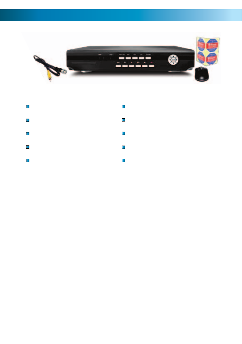
Package Contents
DVR4-2000™ Unit
Remote Control
Operating Instructions
Easy Setup Guide
Power Adapter with Cable
Software CD
Network cable
USB Mouse
BNC to RCA Video Cable
Security Stickers (4 Pack)
If you are missing any of these
components, contact Swann
Communications for assistance.
4
Page 5

Read Before Installation
IMPORTANT GUIDELINES
Do not expose the DVR to moisture• . Water is the arch-enemy of electrical
components and also poses a high risk of electric shock.
Avoid dusty locations• . Dust has a tendency to build up inside the DVR case,
leading to a high risk of failure or even fire.
Only install the DVR in a well ventilated space• . The circuitry and hard
drive in the DVR, like all electronic devices, produce heat, and this heat needs
a way out.
Do not open the DVR case• except to install/swap the hard drive inside. There
are no user serviceable parts inside.
Never open the case whilst the DVR is plugged in• , and never turn the
DVR on whilst the case is open.
Use only the supplied power adaptor.• Other adaptors may cause damage
to the DVR or cause a fire.
Do not cut or modify any cable for any reason.• Doing so will void your
warranty, as well as pose a great risk of fire or electrical shock.
Don’t expose the DVR to sudden bumps or shocks• (for example, being
dropped). The DVR is as robust as possible, but many of the internal components
are quite fragile.
Remember that the DVR is, in all likelihood, going to be left on 24 hours a day, •
7 days a week. Keep this in mind when choosing a location for installation.
5
Page 6

Overview
Congratulations on your purchase of the DVR4-2000!
You’ve chosen a versatile, powerful and great value security monitoring and
recording solution for your home or business. Let’s just take a moment to talk
about some of the great features that the DVR4-2000 offers and some of the
things to think about before installing the system.
4 Channel Monitoring and Recording
The DVR4-2000 can monitor and record four channels simultaneously. You can
configure the recording modes for the four channels quite independently – for
example, you could have two channels recording on a schedule, one recording
constantly and one armed to record on motion. Or any other combination you can
think of!
Powerful H.264 Compression
The advanced video codec used by the DVR4-2000, called H.264, offers high
quality video files at a fraction of the size of older video codecs such as MPEG-2
or similar. Basically, this means you can get store more footage on the DVR’s hard
drive, and that the quality of that footage can be significantly higher than many
older video formats. H.264 has been engineered to provide the highest level of
data compression possible (saving space on your hard drive) whilst maintaining a
high image quality.
Powerful Networking and Remote Access Features
The DVR4-2000 features an Ethernet port, which can be used to connect the
DVR to your home network. With the addition of a high-speed Internet service,
this allows you to remotely access the DVR from any high-speed Internet terminal
on Earth! If that isn’t convenient enough, the DVR also features mobile device
support, allowing you to connect to it from a device running Microsoft Windows
®
Mobile
popular iPhone.
6
or Symbian S60 (3rd edition or more recent), as well as the increasingly
Pulled the DVR out of the box and aren’t sure what to do next?
Check out page 13 for a quick rundown of the setup procedure!
Page 7

Important Information
DEFAULT PASSWORD INFORMATION
To ensure your privacy, this DVR is password protected.
To unlock the DVR for the first time, the default password is “• 123456”.
To ensure your ongoing privacy, we strongly recommend changing the pass-•
word as soon as possible. Choose something that you’ll remember, but that
others would be unlikely to guess.
If you do manage to lock yourself out of the DVR, you’ll need to contact us •
at the Swann Technical Support Telephone Helpdesk - the number is on the
back cover.
Installation Tips & Tricks
One of the most important things to decide early on is where you’re going to install the DVR. There are several considerations to make, and some of them conflict
with one another.
Your DVR needs to be located in a central location to allow you maximum •
options when placing your cameras. This is true whether your cameras are
connected via cables or wirelessly - one way, you’ll have to physically install
cabling, and wireless systems still have a limited range.
On the other hand, your DVR should be installed somewhere secure. If the •
DVR is too accessible it could be sabotaged or removed by an intruder.
Ideally, assuming that you wish to use most features this DVR offers, it should •
be installed close to a network access point. There is, however, no problem using a long network cable - a Cat 5e Ethernet cable up to approximately three
hundred feet (about 90m) should work. Different network cable standards will
offer a longer or shorter range.
7
Page 8
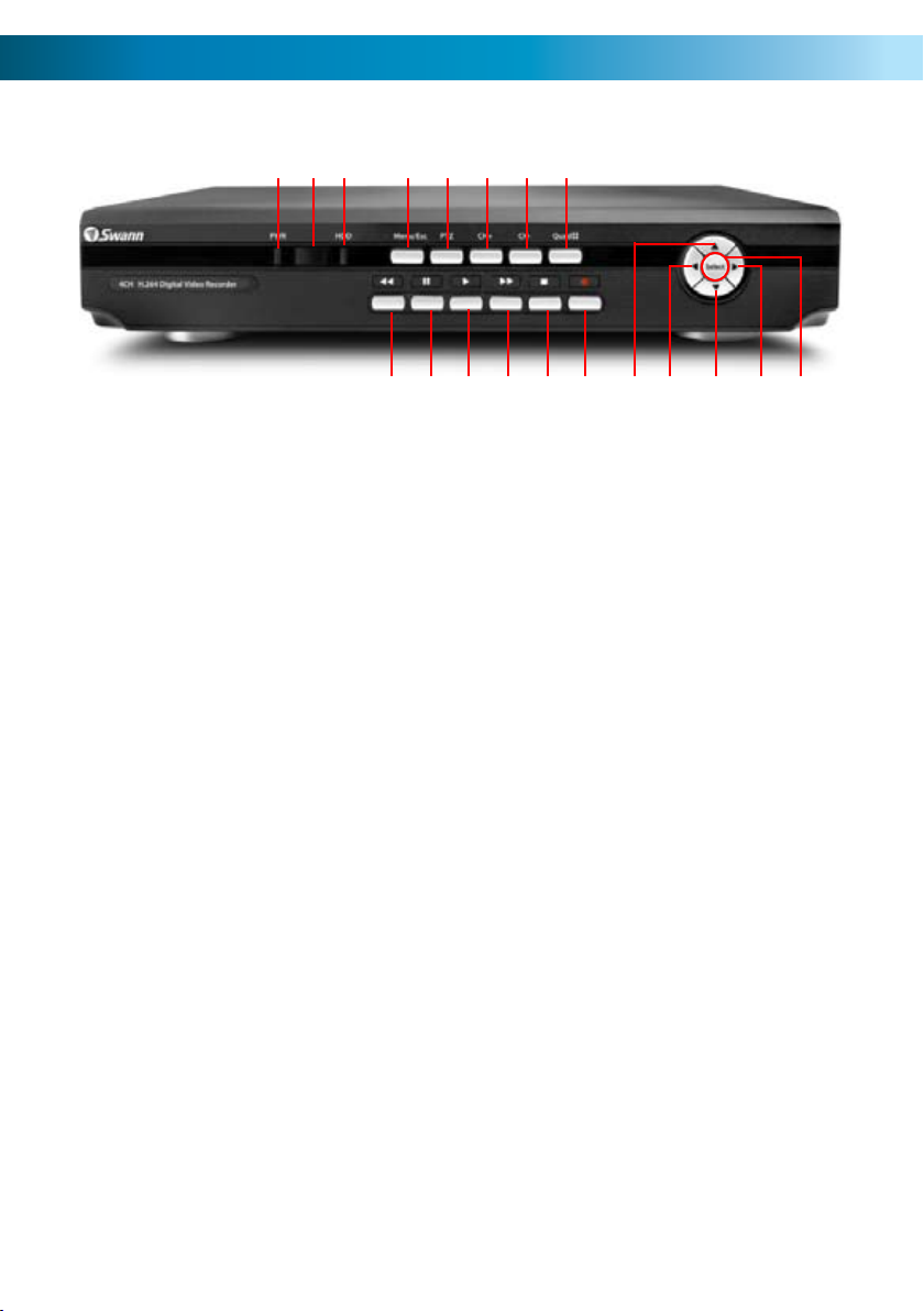
Layout of the Front Panel
1 2 3 4 6 7 8
9510 11 12 13 15 16 17 18 1914
1) Power Indicator: This LED is illuminated when
the DVR is connected to power and switched on.
2) Infrared Sensor: Monitors signals coming
from the infrared remote control. If this sensor is
blocked or obstructed, then the functionality of
the remote will be impaired.
3) Hard Drive Indicator: Lights up when the hard
drive is active. It will flash rapidly when recording
or searching (in time with the read/write cycles).
4) Menu/ESC: One of the primary controls for
navigating through the menus. When in liveviewing mode, it will enter the main menu. When
pressed in the main menu, it will return the DVR
to live-viewing mode. Finally, when in a submenu,
this button will return you to the main menu.
5) PTZ: Opens the Pan, Tilt, Zoom pop-up menu.
This is used to control PTZ capable camera
systems, and will not affect standard cameras.
6 & 7) Previous Channel & Next Channel:
Moves back or forward through available channels
in either live-viewing mode or playback.
8) Quad Mode: Enters split-screen quad-view.
The whole screen is split into four quadrants,
each displaying the images from one camera.
9) Rewind: During playback, this will reverse
the footage. Press multiple times to increase the
speed of the reversing. When navigating through
menus, this button will move the cursor to the
left.
10) Pause: During playback, will pause the current
recording and leave a still-frame on screen. In
live-viewing mode, this will activate the autosequence mode, where the display automatically
cycles through the available camera signals (this
must be correctly configured and enabled to
function correctly).
11) Play: If pressed in live-viewing mode, this will
take you directly into playback mode, and begin
playing the most recent recording. In playback
mode, use it to resume playback after pausing or
stopping a recording.
12) Fast-Forward: During playback, this will
speed up the footage. Press multiple times
to increase the speed of the playback. When
navigating through menus, this button will move
the cursor to the right.
13) Stop: In playback mode, pressing this button
will stop playback.
14) Record: Press to immediately start recording.
This acts as a manual override to the schedule
and motion recording modes. For a channel to be
recorded in this mode (or any other) it must listed
as ‘active’ in the Camera Setup and Record Setup
menus.
15 ~ 18) Arrows: Move the cursor in the selected
direction in the menus.
19) Select: The equivalent of Enter/Return on a
computer keyboard. Use this button to (as the
name suggests) select an option in the menus, or
to confirm an entry.
8
Page 9
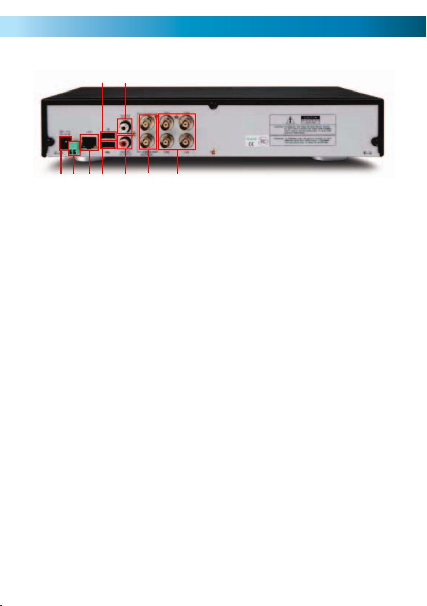
Layout of the Rear Panel
3
5
79
8
1) CH1 ~ CH4 (Video Inputs): These
are the four camera inputs, labelled as
per their channel in the DVR’s interface.
Thus, plug the camera you want to be
associated with Channel 1 into the port
marked CH1 and so on.
2) Video Outputs: This sends a
composite video signal out of the DVR.
Each of the two ports can be connected
to separate monitors. However, there is
no requirement to use more than one
monitor/television – one usually does
the job just fine.
3) Audio Input: One RCA audio input.
This will accept standard line-level
signals (<1V).
4) Audio Output: A mono audio output
channel. These output a standard ‘linelevel’ signal, and can easily be connected
to the audio inputs on a television or
stand-alone audio device.
4
6
1
2
5) USB Mouse Port: For connecting
the included USB mouse (other standard
USB mice will also work). This port will
not accept a USB flash drive – this port
will work with a mouse only.
6) USB Backup Port: For connecting
a USB flash drive for the purposes of
backing up footage.
7) LAN Port: To connect an Ethernet
cable, allowing the DVR to be connected
to a local area network. This network,
in turn, can be used to give the DVR a
connection to the Internet.
8) RS485: For connecting a PTZ (pan,
tilt, zoom) capable system.
9) Power Connection: For supplying
power to the DVR. Use only the supplied
power adaptor, and do NOT change or
modify it in any way. Modifications to
your power supply radically increases
the risk of electrocution or fire, and will
immediately void your warranty.
9
Page 10
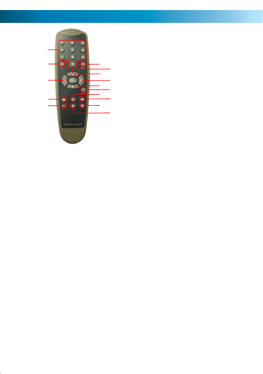
Layout of Remote Control
6) Menu: One of the primary controls
1
2
3
4
5
6
8
10
12
14
7
9
11
13
15
1) 0 ~ 9 (Numeric Buttons): Used
to input numbers. 1 ~ 4 can be used
as quick channel changing buttons
in a similar manner to a television,
and these will work during either liveviewing mode or playback. Additionally,
the numeric buttons will be used when
inputting any numerical information –
most often, your password.
2) ALL: Activates or deactivates the
entire area shown on screen to be
armed for Motion Detection recording
mode. Motion Detection will need to
be correctly configured for this button
to function as described.
for navigating through the menus.
When in live-viewing mode, it will enter
the main menu. When pressed in the
main menu, it will return the DVR to
live-viewing mode. Finally, when in a
submenu, this button will return you to
the main menu.
7) SEL (Select): The equivalent of Enter/
Return on a computer keyboard. Use
this button to (as the name suggests)
select an option in the menus, or to
confirm an entry.
11) Mute: Will not affect the function
of this DVR.
12) Play: If pressed in live-viewing
mode, this will take you directly into
playback mode, and begin playing the
most recent recording. In playback
mode, use it to resume playback after
pausing or stopping a recording.
4) Rewind: During playback, this will
reverse the footage. Press multiple times
to increase the speed of the reversing.
13) Fast-Forward: During playback,
this will increase the speed of playback.
Press multiple times to increase the
speed of playback further.
3, 7, 8, 9 & 10) Arrow Buttons: Moves
the cursor in the appropriate direction
when navigating menus.
5) Record: Press to immediately start
recording. This acts as a manual override
to the schedule and motion recording
modes. For a channel to be recorded in
this mode (or any other) it must listed as
‘active’ in the Camera Setup and Record
Setup menus.
10
14) Stop: In playback mode, pressing
this button will stop playback.
15) Pause: During playback, will pause
the current recording and leave a stillframe on screen. In live-viewing mode,
this will activate the auto-sequence
mode, where the display automatically
cycles through the available camera
signals (this must be correctly configured
and enabled to function correctly).
Page 11
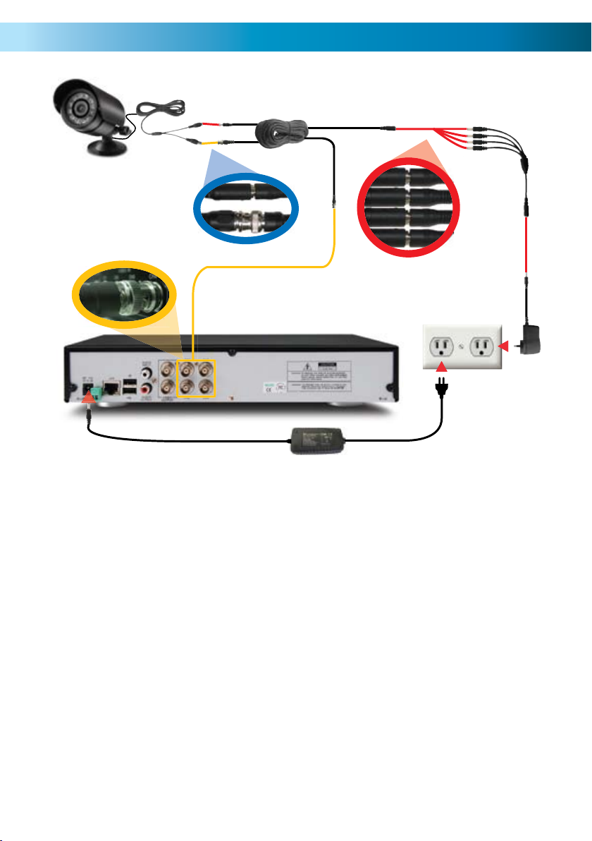
Connecting Cameras
Connect the power and BNC 1.
ends of the security camera to
an extension cable.
Connect the DC end on the 2.
extension cables to the 4 way
power splitter plugs.
Connect the camera power 3.
supply to the other end of the
power splitter.
Connect the BNC end of the 4.
extension cables to the camera
connections on the back of
the DVR unit (CH1, CH2, CH3 &
CH4).
Connect the DVR power supply 5.
plug into the power supply
socket on the back of the DVR.
Plug in the camera power 6.
adapter and the DVR power
adapter to mains power outlets.
11
Page 12
Navigating the Menus
There are two main ways to navigate through the menus on the DVR. One way is
to use the buttons on the front panel of the DVR and/or the remote control. The
other way is to use the included USB mouse.
Front Panel / Remote Control
For an explanation of the functions of the buttons on the DVR and the remote
control, see pages 6 and 8, respectively. Many of the controls operate in a similar
manner to controls on a DVD player or similar. However, due to the specific and
multi-channel nature of the DVR, the functionality of some buttons may not be
immediately obvious.
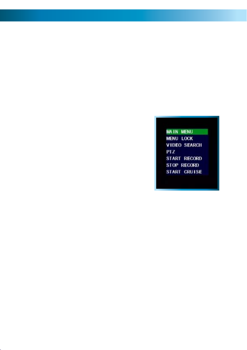
USB Mouse
When a USB mouse is attached to the DVR, it
allows for easy navigation and operation of the
menus. In this capacity, the mouse functions in
a very similar manner to the mouse attached to
a computer. The left mouse button is used to
select, confirm choices and otherwise interact
with the menu system. The right mouse button
opens the pop-up menu (when pressed in liveviewing mode) or exits a menu (when pressed
whilst in the menu system).
The pop-up menu, accessed by
right-clicking the mouse in live-
viewing mode.
IMPORTANT - Remembering to Apply Your Changes
When you’re using the menus to change settings or values, none of your changes
will be saved until you choose the “Apply” option, which is usually located in the
lower right-hand corner of the screen.
Always select the APPLY button before leaving a menu
if you want to save the changes that you have made.
There are two reasons why the “Apply” button needs to expressly selected. For
one, it helps prevent accidental modification of the DVR’s settings while you’re
navigating other menus or similar. Secondly, the DVR only checks and loads the
settings you’ve modified when the apply button is pressed. This is important to
prevent the DVR operating erratically or performing an unintended operation
whilst settings are in the process of being modified.
12
Page 13

Using the On-Screen Keyboard
As the DVR doesn’t have a keyboard, when you have to enter text the DVR will
present you an on-screen ‘keyboard’. This will automatically appear when you
select a text field which allows you to enter a value.
If you want to change the type of characters
being entered, click the ABC button on the right
of the keyboard - this will cycle through the
modes available. You can enter letters, numbers
or symbols, each with their own mini-keyboard.
Getting Started
If you’ve just unpacked your DVR and are not sure where to begin setting up your
system, here’s a quick rundown of the most important things that need to be set up.
Test your system.• Before installing cables into walls, it’s a great idea to plug
everything in and make sure it all works. This is particularly true if you’re
using additional cameras to any that came with the DVR (this DVR is available
stand-alone or in a kit with cameras). We do our very best to ensure that the
equipment reaching you is of the highest quality and will work out of the box,
but accidents do occur in shipping and sometimes components inevitably fail.
Better to find out now than once everything is screwed in place!
Then, once the DVR is on and working, the first thing to do is to • set your
password (see page 42 for details on how to do it).
Set the Date and Time• (page 41 for details) to ensure that, once you start
recording, you are able to index and search the recorded footage easily. Also,
if using the DVR’s footage in any legal proceedings, then having an accurate
date and time on your footage becomes quite crucial.
Check your hardware• - specifically, and most importantly, the hard drive
(see pages 30 & 31). This is where all your footage will be stored, so it’s quite
important to ensure that it is functioning correctly.
Setup your recording modes and/or schedule• (pages 18 - 21) to make
sure that the DVR will record what you want it to, and at the right time.
OPTIONAL (Advanced Users):• Configure your network settings (pages 22 -
23 & 50 - 51).
13
Page 14
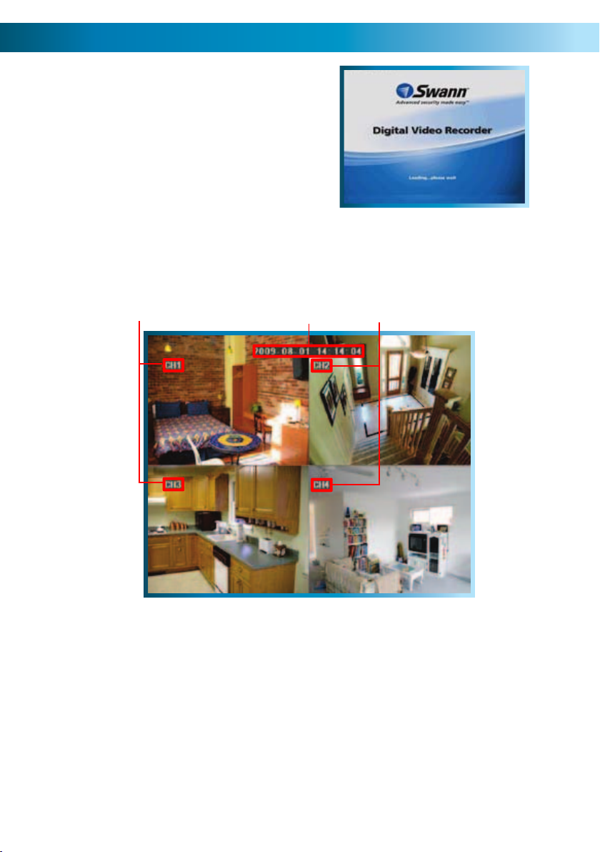
Starting the DVR
Once the DVR has been connected to
power, switch it on by using the power
switch on the rear panel. The DVR takes
approximately 45 seconds to boot up,
during which time the image to the right
will be displayed.
The default mode of the DVR is live-viewing mode. This is the mode which monitors
the images coming from your cameras in real-time, and allows you to configure
your recording and channel options. The DVR automatically starts in live-viewing
mode, with quad-view enabled, as shown below.
3
21
The main display windows showing 1.
channels 1 and 3. The highlighted
portion of the image is the channel
identification tag which in this case
is set to the default value of “CHx”
where “x” is the number of the
channel in question.
The display windows showing 2.
channels 2 and 4. These are labeled
as their counterparts 1 and 3.
14
The 3. current time and date are
displayed at the top of the screen.
This will be the date stamp applied
to all recordings. If this is incorrect,
you’ll need to set the time and date
in the DVR to their correct values
(see page 41).
Page 15
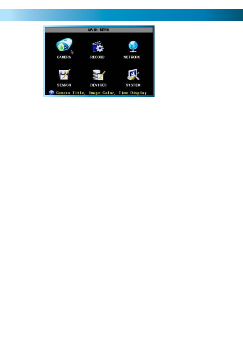
The Main Menu
The MAIN MENU of
the DVR. In this picture,
the mouse cursor is
currently highlighting
the CAMERA icon.
Camera (Display Setup): The camera
menu contains all the options for setting
up how the DVR interfaces with and
displays the images from the cameras
connected to it. This is where channels
are enabled or disabled in live viewing,
and where the AUTOSEQ (Automatic
Sequence) function can be configured.
Record: Where you can configure the
recording options for the DVR. You can
set channels to be armed for recording
constantly or on a schedule, and set the
recording resolution, quality and size.
You can also enable or disable the audio
channel. Additionally, the recording
function for some or all channels can
be disabled entirely.
Network: Where you can configure
the DVR to operate on your home
network and over the Internet. This is
the most complex aspect of setting up
the DVR, and requires a good working
knowledge of networking methods and
protocols.
Search: Where you look for footage of
a specific event. You only need to know
the date and time that the incident that
you are looking for occurred. You need
not know exactly - you can specify a
range of times and/or dates. The DVR
will list all recordings made in between
the start and end points you specify.
Devices: Here you can find the setup
and configurable options for the devices
which can be connected to the DVR.
These devices are in order:
HDD: The hard drive, where you store
your footage.
ALARM: The circumstances which will
trigger the DVR to record or issue an
alert of some kind (such as an email).
PTZ: For setting up the DVR to work
with Pan, Tilt, Zoom camera systems.
MOBILE: For setting up the DVR for
access via a compatible mobile/cell
phone.
MOTION: To configure how and where
the DVR looks for motion. This can be
used as (and is recommended as) the
primary recording mode of the DVR.
System: All the remaining options and
sub-menus. Here is where you set the
Date and Time and your Password,
change the video output settings,
change languages, or the automatic
maintenance schedule of the DVR.
15
Page 16

The Camera (Display Setup) Menu
The DISPLAY SETUP MENU
of the DVR. In this picture,
the mouse cursor is
currently highlighting the
CH1 title field.
Naming Channels
You can change the name of any channel from the default (and rather drab) “CHx”
to anything that you would like (provided it’s short enough to fit in the box). A
descriptive name on each channel often makes it easier to remember what camera
is where, and which channel would have captured an event you might be looking
for.
Title: The name that will be displayed over the image from a channel. Simply
highlight this box and enter the new name you would like.
Position: Where the title of the channel is displayed on screen. You can choose
any of the four corners of the display (UPLEFT being the top left-hand corner, and
DOWNRIGHT being the lower, right-hand corner).
AUTOSEQ (Auto-Sequence)
When AUTOSEQ (automatic sequencing mode) is
engaged, the DVR will automatically cycle through all
available channels, displaying each in turn expanded to
fill the entire screen.
In the AUTOSEQ drop-down menu, you can select how
long you’d like each channel to appear, as well as the
quad-view mode. Each can be configured individually,
so you can fine tune exactly how long you’d like each
channel to be visible for. The DVR will skip channels
which been disabled during the auto-sequence.
16
Remember: After making changes to the settings press/click the APPLY button.
Page 17
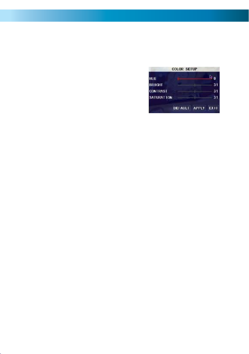
Color Setup
You can fine tune the look of each channel individually by adjusting the HUE,
BRIGHT (brightness), CONTRAST and SATURATION values for each channel. Just
select the SETUP option under the COLOR heading to open the dialog window.
This is useful if peculiar lighting conditions,
a non-standard camera or a conspicuously
colored object in the frame cause the display
to be inconveniently tinted, or over/under
exposed. Basically, this will help fix something
that just doesn’t look ‘right’.
HUE: Changes the color mix of the frame (this can have very dramatic results).
BRIGHT: Changes how light all tones in the image appear.
CONTRAST: Increases the difference between the blackest black and the whitest
white in the image. Useful if sections of the image “grey out” but setting the
contrast too high will degrade image quality.
SATURATION: Alters how much color is displayed in the image. The higher the
saturation, the more bright and vivid colors will appear to be. Again, setting this
too high can degrade image quality.
LIVE Viewing - Enabling and Disabling Channels
Monitoring something that you’d rather keep private/secret/unknown to the casual observer? No problems. You can alter which channels appear when in live
viewing mode, and which ones appear later on.
To do so is simple: simply locate the DISPLAY drop down menu - it only contains
two options, ON or OFF. Simply change the value to OFF and that channel will now
appear to be blank in live viewing mode. Images on the channel in question will
still be recorded - and you’ll see it as normal in playback mode.
Display Time
In the nearby DISPLAY TIME drop down menu, you can select whether you want
to see the time displayed on the channel in either live viewing mode, or when
recording. The time will always be recorded in the event list and in the footage’s
meta-data (the information included in the file such as when it was recorded - you
can access this later) - this simply changes whether or not you see it in the main
view screen.
Remember: After making changes to the settings press/click the APPLY button.
17
Page 18
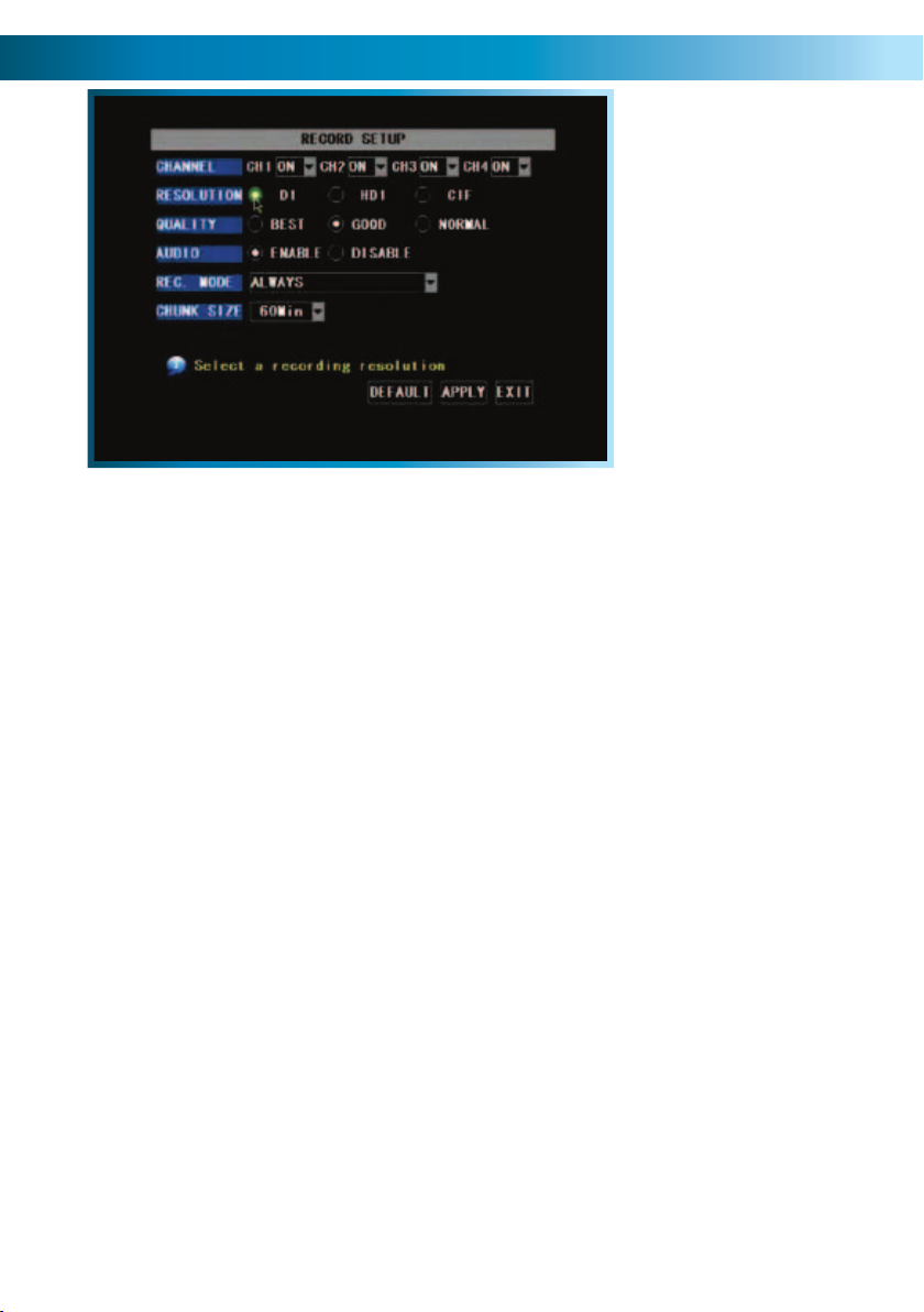
The Record Setup Menu
The RECORD SETUP
MENU of the DVR. In this
picture, the mouse cursor
is currently highlighting the
D1 resolution button.
In the RECORD SETUP submenu you can choose which channels will be active during
recording, change the recording quality, enable & disable audio, select record more
and Chunk Size (the maximum size of each recorded file). This menu contains
many of the most important settings on the DVR, and correctly configuring them
is important to the ongoing smooth operation of the unit.
Turning Channels ON or OFF
Using the drop-down menus in the CHANNEL line, you can turn the recording
functions for a channel ON or OFF. Turning a channel OFF in this way means that
it will never be recorded until turned ON again. This can be set independently of
the channel being enabled/disabled in live-viewing mode (that is, a channel can be
seen but not recorded or vice-versa).
Resolution and Quality
The term “Resolution” refers to how many pixels (the individual little dots which
together make up an image) will be recorded in your image. The highest setting
D1 will use a resolution approximately equal to that of a DVD, whereas CIF will use
one quarter this many pixels. HD1 offers a middle-ground between these settings.
Higher resolutions give sharper images, but each frame of video takes up more
space on your hard drive. Thus, the DVR will record fewer images per second
(frames) at high (D1) resolution. Lower resolutions, particularly CIF, do not have
nearly as much detail, but will record many more images per second.
The higher the quality selected, the more detail will appear in your footage. Best
quality video takes up more space on your hard drive than normal quality. Good
quality offers a compromise between the size of and amount of detail in your
footage.
18
Remember: After making changes to the settings press/click the APPLY button.
Page 19
Audio
The audio recording function can be turned enabled or disabled here. If you have
no audio recording equipment (such as a microphone) attached to your system or
simply do not want to record sound, then we suggest disabling the audio here - it
will save a small but noticeable amount of hard drive space.
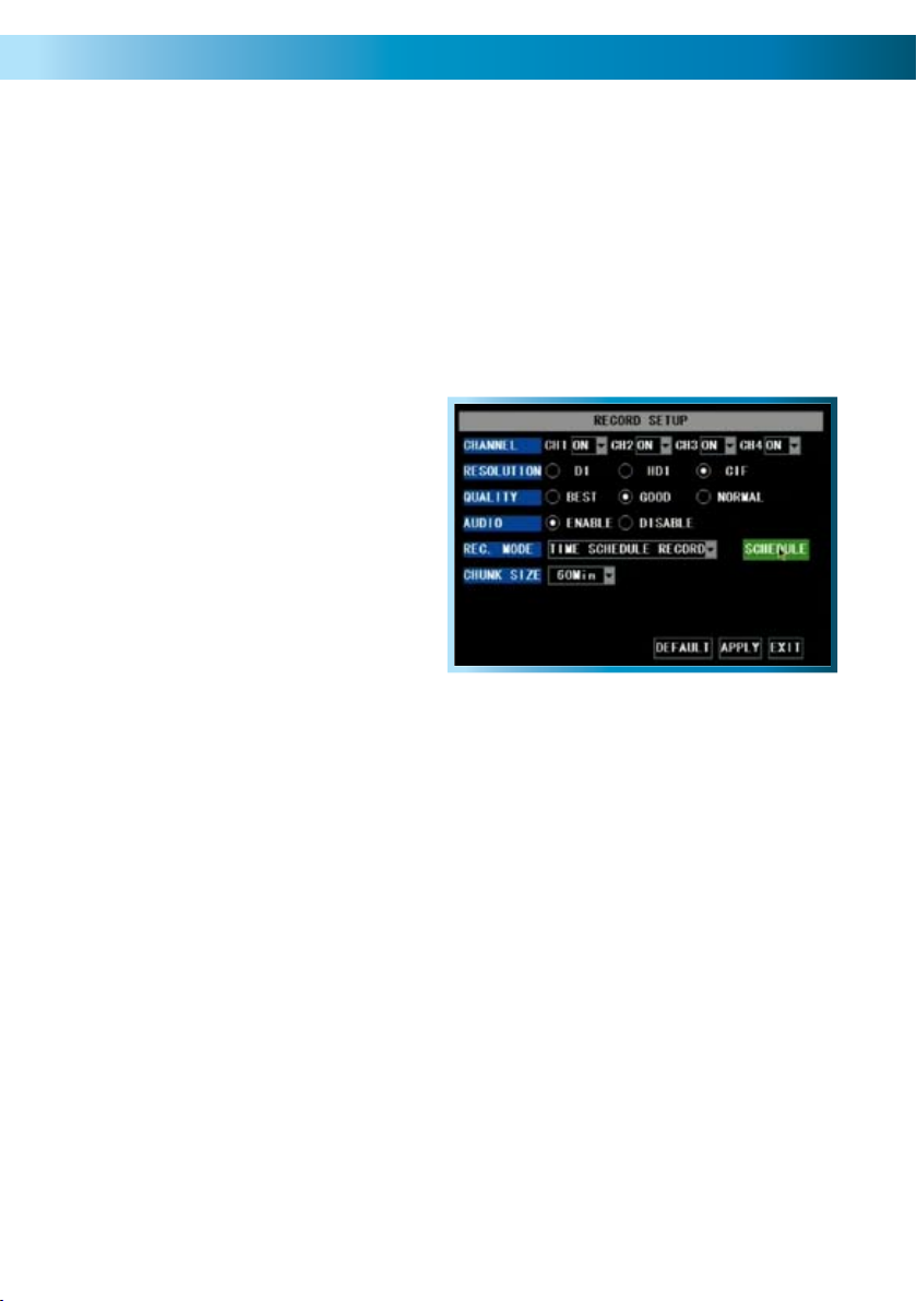
Rec. Mode (Recording Mode)
There are two recording methods which can be chosen here, the choices are
ALWAYS or TIME SCHEDULE RECORDING.
If you want the DVR to record
constantly then choose ALWAYS. On
the other hand, if you want the DVR
to either record at specific times, or
when motion is detected during the
pre-defined times, then choose TIME
SCHEDULE RECORD. When you select
the latter, a SCHEDULE button will
appear, allowing you to program a
custom recording schedule.
Chunk Size
Chunk Size is a measurement of how long the DVR will record for before splitting
the output file into discrete units. Chunks are something like the scene numbers
on a DVD - though the video is broken up into separate units, it will still play
through as one continuous movie (unless interrupted by the schedule or motion
detection turning the recording on or off).
The right settings for you depend on a number of factors. Larger Chunk Sizes
use slightly less space on the HDD and keep related events together. Also, larger
Chunk Sizes make navigating through the File List a bit easier (see page 24).
Smaller Chunk Sizes are more resistant to file corruption, and make backing up
slightly quicker. If you don’t want to worry about setting Chunk Size, you can leave
it on the default value; it will make little difference to the day-to-day running of
the DVR.
Remember: After making changes to the settings press/click the APPLY button.
19
Page 20
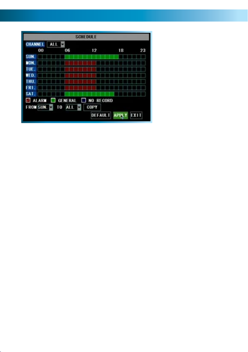
The Recording Schedule
The SCHEDULE screen. Currently,
the schedule is configured to
record on Alarm Events (i.e. Motion
Detection) from 6:00am to 1:00pm
weekdays, and record constantly
between 6:00am and 6:00pm on
At all other times, the DVR is
configured not to record anything
The first step in setting the schedule is choosing which channel you’d like to set
the schedule for. From the CHANNEL drop-down menu, select the channel you’d
like to set the schedule for.
If you’d like to set the schedule for more than one channel at a time, you have two
options. One option is to manually enter the same information for each channel
individually.
weekends.
at all.
The other option is to choose ALL from the CHANNEL drop down menu. Selecting
this will apply the settings in the schedule to all channels on the DVR. If you want
to set a base schedule for all channels, and then configure them individually, select
ALL, set your basic schedule, and then fine tune channels one at a time. Changing
the ALL schedule will overwrite any schedule already set for individual channels.
The DVR schedule can be set to record using three different record modes.
ALARM: Will record only when the alarm function has been triggered.
GENERAL: Will record based on the general settings on the DVR - either constantly,
or when motion is detected, depending on your motion detection settings.
NO RECORD: As the name suggests, the DVR will not record.
20
Remember: After making changes to the settings press/click the APPLY button.
Page 21

Setting the Schedule
The first step in setting the schedule is choosing which channel you’d like to set
the schedule for. From the CHANNEL drop-down menu, select the channel you’d
like to set the schedule for.
If you’d like to set the schedule for more than one channel at a time, you have two
options. One option is to manually enter the same information for each channel
individually.
The other option is to choose ALL from the CHANNEL drop down menu. Selecting
this will apply the settings in the schedule to all channels on the DVR. If you want
to set a base schedule for all channels, and then configure them individually, select
ALL, set your basic schedule, and then fine tune channels one at a time. Changing
the ALL schedule will overwrite any schedule already set for individual channels.
Copying and Pasting Schedules from day to day
Rather then enter the same schedule information multiple times for each day you
wish, you can use the COPY function.
To copy the schedule settings from day to day, select the day you’d like to copy
from on the first drop down menu. Then, select the day you’d like to copy the
schedule to from the second. If you’d like all days to operate on the same schedule, choose ALL from the second drop-down menu.
Using the arrow buttons or the mouse, highlight the COPY button, and left click
or press select. The schedule for the selected day will be copied to the day(s) you
have selected.
Remember: After making changes to the settings press/click the APPLY button.
21
Page 22

The Network Configuration Menu
This is the NETWORK SETUP screen.
This is the most technically complex
aspect to setting up the DVR, and does
require a working knowledge of network
If you are unfamiliar with networking, then we
suggest talking with a professional - ideally,
the same person who installed your network,
as they’ll know exactly how it’s configured and
Configuring your DVR and your home network can be a tricky process - and these
two pages are not nearly long enough to cover it.
TYPE: Here you can choose between the three different types of networks that the
DVR can be connected to. The three types of networks are:
DHCP (Dynamic Host Configuration Protocol) is a system where one device on
your network (usually a router) will automatically assign IP addresses to devices
connected to the network.
technologies.
how best to setup the DVR.
Devices connected to STATIC networks need to have their IP addresses manually
defined, as there is no device dedicated to automatically assigning addresses.
PPPoE (Point to Point Protocol Over Ethernet) is an advanced protocol which allows
the DVR to be connected directly to a DSL line, without the need for a router or
gateway. This is recommended for advanced users only.
More information about networking the DVR as well as
remote access from a PC or mobile device can be found in
the Remote Access section. See pages 50 - 55 for more.
Additionally, we have some resources available online at
www.swannsecurity.com to help walk you though the process.
22
Remember: After making changes to the settings press/click the APPLY button.
Page 23

MEDIA PORT: This is the port that the DVR will use to send information through.
The most important things are that:
Nothing else share this port. The default port number is 9000, which is not 1.
used by many other devices/programs. However, particularly if you have
another DVR or DVR-like device, something might be using this port already. If
this is the case, change this value to be unique.
That this port is forwarded from your router to the DVR (this process is 2.
called Port Forwarding). Check out or website (www.swannsecurity.com) for
supporting information and an online guide which covers port forwarding
for various popular routers/gateways. Forwarding a port is something like
opening up a fast-lane for network traffic to get to and from your DVR - it will
significantly speed up the flow to and from the DVR stopping ‘traffic jams’
which can prevent the DVR operating correctly via the network.
WEB PORT: This is the port through which you will be able to communicate with
the DVR. Like the Media Port, it will need to be forwarded properly in order to
ensure smooth, latency-free communication.
IP ADDRESS: Just as houses and businesses need to have an address which
identifies their location on the road network, so too do computers and other
devices need addresses (called IP ADDRESSES) to identify their position on the
electronic network. The DVR uses IPv4 addressing, which consists of four groups
of numbers between 0 and 255, separated by periods. For example, a typical IP
address might be “192.168.1.24” or something similar. The most important things
are that the first three numbers (in the above example “192.168.1.xxx” match the
other devices, and that nothing else on your network share the last number.
SUBNET MASK: If the IP address is like a street address, then a subnetwork is like
your neighborhood. This will be formatted in a similar way to the IP address (ie. four
numbers up to 255 separated by periods) but contain very different numbers. In
the above example, the Subnet Mask might be something like: “255.255.255.0”.
It must be the same as the other devices on your network.
GATEWAY: This is the address of the “way to the Internet” - to continue the road
analogy, this is like your local access point to the highway. This is an IP address
in the same format as the others, and is typically very similar to the IP address
of the DVR. To continue the above examples, it might be something such as:
“192.168.1.254”.
DNS: A “Domain Name Server”. Everything on the Internet is located via an
IP address - however, for ease of use, we associate domain names (such as
“www.exampledomainname.com”) with those IP addresses. This index is stored in
many locations online, and we call those locations DNS servers.
Remember: After making changes to the settings press/click the APPLY button.
23
Page 24

The Video Search Menu
The SCHEDULE screen. Currently,
the schedule is configured to
record on Alarm Events (i.e. Motion
Detection) from 6:00am to 1:00pm
weekdays, and record constantly
between 6:00am and 6:00pm on
At all other times, the DVR is
configured not to record anything
Video Search
In the VIDEO SEARCH screen you can search for a specific day for a recording
and view it in playback mode. This is useful for hunting a specific recording of an
incident if you know the time and date it occurred. To search you need to input the
date of the video then select the hour of the recording.
Note that if you don’t know the exact day you want to search input just the MONTH
& YEAR then click the SEARCH button. If you want to be really vague, or look at a
really long list, you can input the YEAR alone.
weekends.
at all.
All the days for that month will appear on the monthly calender. The highlighted
days are the days with recordings, color coded to represent the recording mode
which triggered the recording at the time (where red = alarm recording; green =
normal recording).
To execute a Video Search:
Scroll over then left click the date numeric field, or highlight it using the arrow •
keys and press select.
Select a digit to alter. Once selected, it will be highlighted red and can be •
edited. You will see a yellow pop up keypad. Scroll or move over the digits on
the keypad & left click or press select to input the date. Note that the first two
digits of the year (2 & 0) cannot be changed.
Highlight the SEARCH button, and left click or press select. •
Alternately to bypass the File List choose PLAYBACK instead of SEARCH. •
Playback will start with the first recording made during the interval chosen.
24
Remember: After making changes to the settings press/click the APPLY button.
Page 25
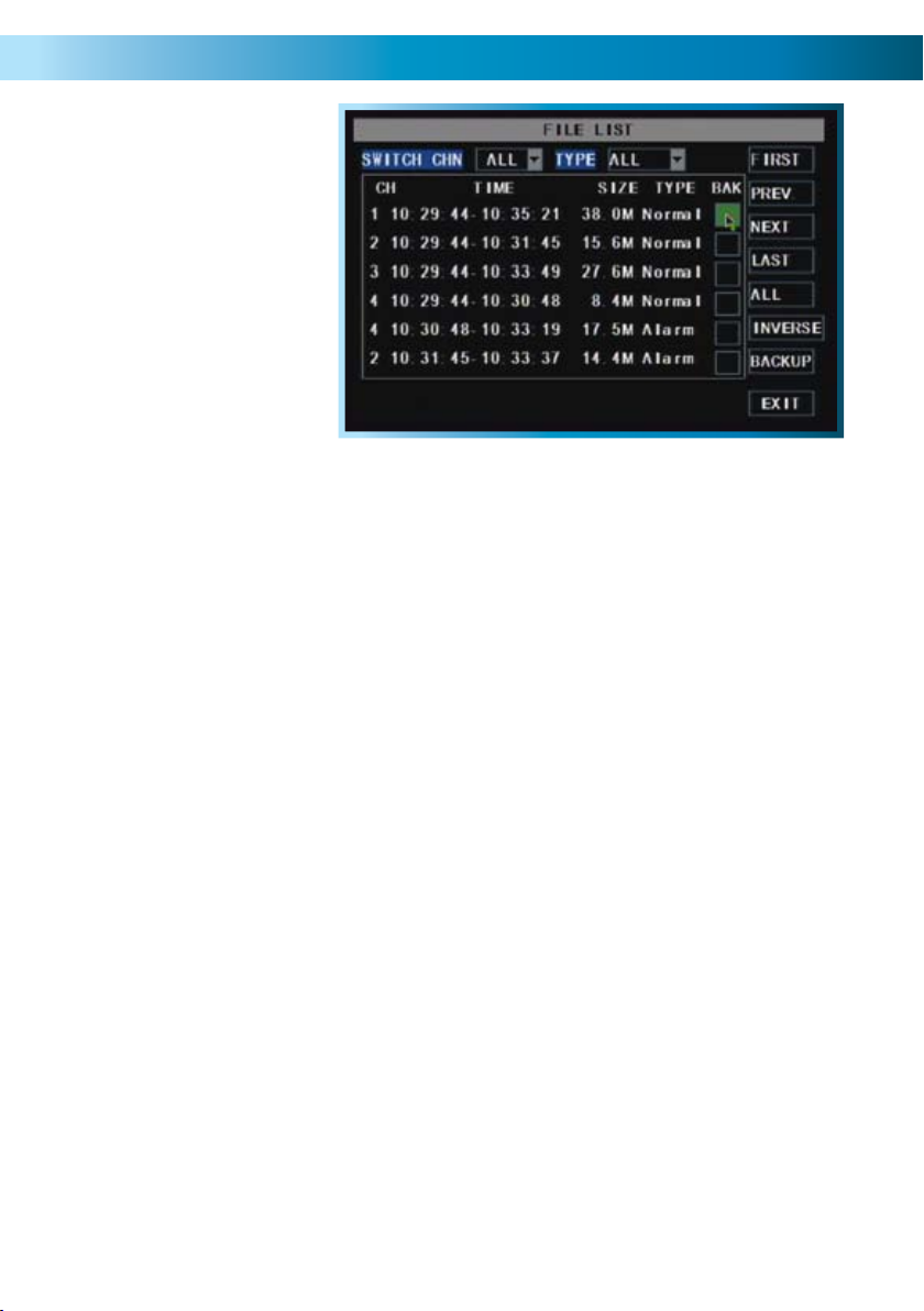
The File List & USB Backup
The FILE LIST screen.
This is the main screen you’ll use
when locating specific incidents
and recordings.
USB Backup Instructions
First, insert a USB flash drive into the USB port on the back of the DVR. Note •
that inserting a flash drive into the mouse port will not work correctly.
Make sure there are no files on the USB flash drive that you wish to keep, as •
data already on the drive may be lost.
Highlight the BAK check-boxes which correspond to the recordings that you •
wish to backup, and left click or press select.
You can backup multiple recordings at once, as long as their cumulative size •
will fit on the USB flash drive you have inserted into the DVR.
Highlight the BACKUP button, and left click or press select to start the backup •
process.
Notes:
Backing up footage is not an instant process. Copying the may be a time consuming
process, and can take up to as long as the half the time of the recordings you
wish to backup, typically about 1/6th the time. For example, if you wanted to
backup one hour’s footage from two cameras, allow up to an hour for the backup
procedure to be executed.
The backed up footage is stored on the flash drive in the same format as it is stored
on the DVR. This means that the backed up footage will not play in a computer as
a standard video file - you’ll need to use the dedicated playback software which
comes on the mini-CD included with the DVR. Instructions on how to install and
use this software can be found later in this manual (starting on page 56).
Remember: After making changes to the settings press/click the APPLY button.
25
Page 26
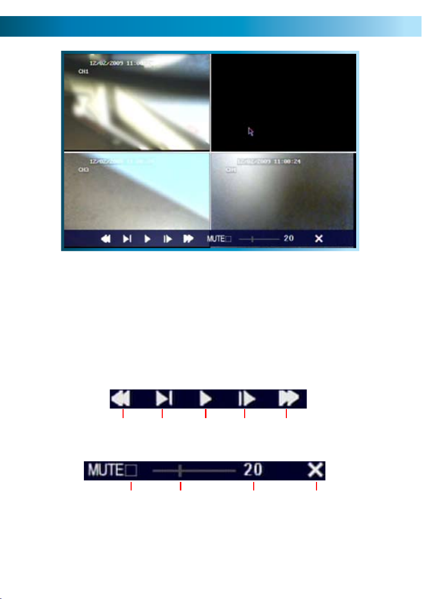
The Playback Interface
This is an example of the PLAYBACK interface,
currently playing back four channels simultaneously in quad view.
Channels 1, 3 and 4 were actively recording.
Channel 2 was not recording at this time - hence the display appears blank.
(The image content has been intentionally blurred.)
26
The playback controls are displayed across the bottom of the screen.
They are as follows:
Rewind Pause Fast
Mute
Remember: After making changes to the settings press/click the APPLY button.
Slow
Volume
Bar
Play
Volume
Level
Forward
Close
Playback
Page 27

Playback Controls
The playback controls work in a similar manner to those you’ll find on a DVD
player or VCR. The playback controls affect all channels being played back
simultaneously.
Rewind: Reverses the footage. Pressing this button multiple times will
increase the speed at which the footage plays in reverse. Note that,
as the H.264 compression used to encode the video is designed
to play forwards, it requires considerably more processing power
to decode in reverse. For this reason, playback in reverse will not
be smooth.
Slow: Press to slow down playback. Pressing once will reduce the
playback speed to ½ speed, pressing it again will slow the speed
to ¼, and pressing it a third time will reduce the speed to ⅛.
Play: Will play footage if paused.
Pause: Will pause playback, retaining still images on the screen.
Fast Forward: Increases the speed of playback. Pressing the button multiple
times will increase the rate of playback up to 8x.
Mute: Checking this box will stop audio playback. It will not affect the
audio track on the recorded footage.
Volume Bar: Adjusts the volume during playback. For the best audio quality
this should be set relatively high, with the volume of the television
or stereo system turned down appropriately.
Volume Level: A numerical representation of the current volume, as set on the
Volume Bar.
Close Playback: Closes the playback window and returns you to the event list.
Remember: After making changes to the settings press/click the APPLY button.
27
Page 28
Playing Backed Up Footage on a PC
The video files which the DVR backs up are not playable by standard multimedia
software. This means that your usual media player is not going to be able to open
or display footage from the DVR. The main reason for this is that footage from the
DVR is always made of multiple channels of video which are synchronised into one
data stream.
Fortunately, the DVR automatically copies the program you need to play back the
footage to the same USB flash drive you back up footage to. All you need to do is
install this program, and use it to access the other data on the thumb drive.
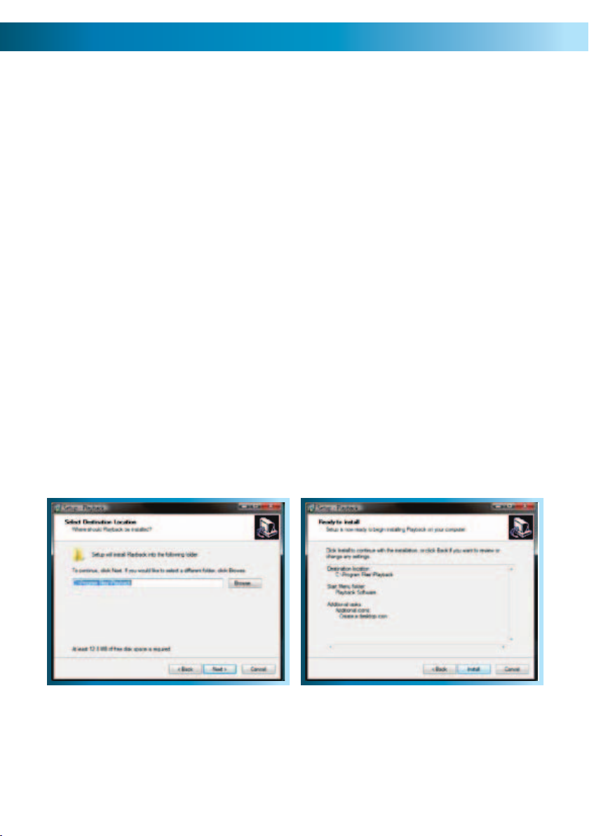
Installing the Playback Software
To install the playback software, locate the file on the included CD named
“PlaybackSetup_2.3.0.4.exe”. Note that the numbers on the end may change
(particularly if you’ve downloaded an updated version) as we are constantly making
updates and improvements to our software. Run this setup file.
Follow the installation prompts - you’ll be asked where you’d like to install the
software and the shortcuts to access it. We suggest that the default options are
usually the best choice - only change these if you have a very specific idea about
where you want the software to be installed. Once you’ve made these choices,
simply wait while the installation is processed.
NOTE: This software is compatible with Windows operating systems only (XP and
more recent versions). Also, it will only operate on 32-bit versions of Windows (not
64-bit - the incompatibility is due mostly to incompatible drivers).
28
Page 29
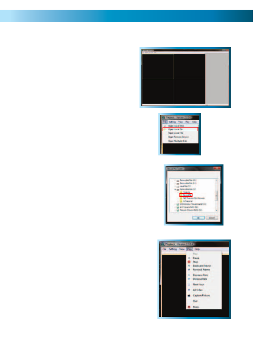
The Playback Interface
Assuming that you’ve used the default
installation paths, you can access the
playback software by selecting the desktop
icon named Playback Software, or finding
the program group of the same name in
your Start Menu.
This will take you to the default interface
of the playback software, as shown to the
right.
Opening Files:
Open the File menu, and choose “Open Local
Folder”. Navigate to the USB drive you have
backed up footage to, and select the folder on
that drive called “RecordFile”.
Playback Controls:
The playback controls are located in the menu
named “Play”.
The Play, Pause, and Stop options work as their
counterparts would on a DVD player. Decrease
Rate and Increase Rate work like fast-forward
and slow motion functions.
Use the Backward Frame and Forward Frame for
precise control - they will move back or forward
the smallest amount possible (the frame rate is
determined by the settings used to record the
video).
Use the Capture Picture function to save a
single picture as a bitmap (BMP) file. The Mute
function will disable audio playback. OSD refers
to the on-screen display.
29
Page 30
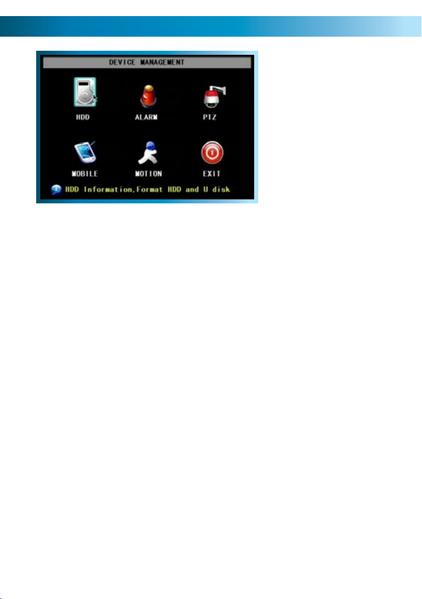
The Device Management Menu
This is the DEVICE MANAGEMENT
menu. Here you’ll find options to
customise and configure settings
for:
Your Hard Drive•
Alarm Settings•
PTZ (Pan, Tilt, Zoom) Devices•
Access from Mobile Devices•
Motion Detection•
HDD
For accessing information about your hard drive. This is where you go to correct
or analyze any problem with your hard drive. Additionally, you’ll be able to see at
a glance how much recording time you have left at your current quality settings,
as well as being able to format (erase all data from) the hard drive here. You can
format flash drives from this screen as well.
Alarm
For configuring the DVR’s alarm and auto-email settings. Also, this is where you
can configure external alarm sensors - this is recommended for advanced users
only.
PTZ
The setup window for configuring the DVR to act as a PTZ (Pan, Tilt, Zoom)
controller. Recommended for advanced users.
Mobile
For configuring the DVR to interface with mobile devices (such as an iPhone or
mobile devices running Microsoft Windows Mobile® or Symbian S60® 3rd Edition
or higher) .
Motion
For setting up the motion detection features of the DVR. We suggest that motion
detection is, under most circumstances, the most practical recording method for
the DVR to employ.
30
Remember: After making changes to the settings press/click the APPLY button.
Page 31
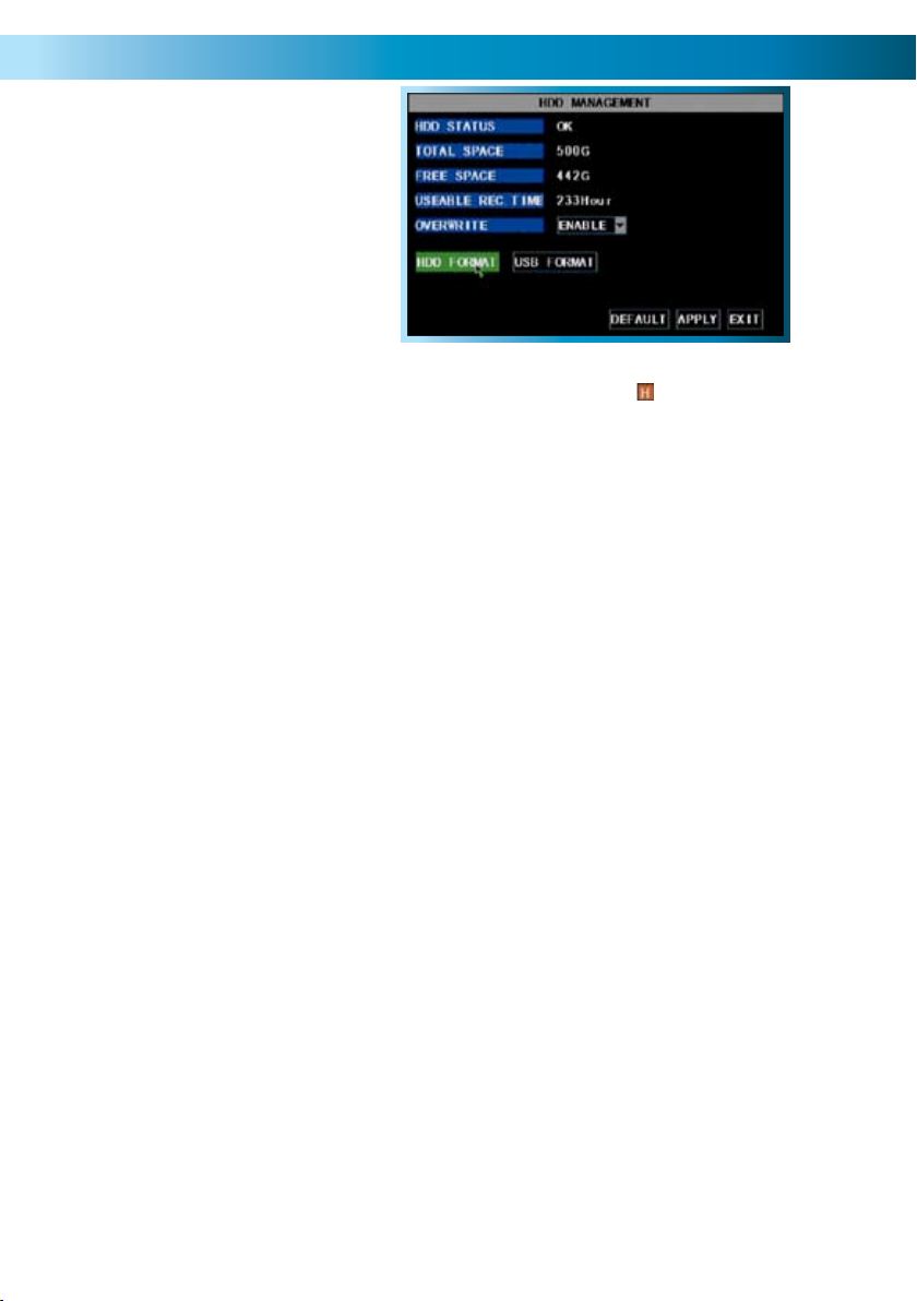
The HDD (Hard Drive) Management Screen
This is the HARD DRIVE (HDD)
MANAGEMENT screen. All aspects of the
hard drive can be managed from this screen.
Additionally, this is the place to go if you
want to know exactly how much space
is left on the hard drive, and how much
footage you can record to it.
Pictured with HDD FORMAT highlighted.
HDD STATUS: If the hard drive is not installed properly you will see a message
saying NO DISK FOUND. The live view screen will display the icon on the bottom
of Channel 1’s display if the hard drive is not being detected.
TOTAL SPACE: Total size of the hard drive currently installed.
FREE SPACE: Total amount of freespace available on the hard drive currently installed.
USEABLE REC. TIME: Free space currently available in hours, calculated based on
your current record quality settings.
OVERWRITE: When set to ENABLE the DVR will record over the oldest files on the
hard drive. This is the default setting, and probably the most preferable, as the DVR
will always be able to record events as they happen. However, it does mean that
you’ll need to get important events off the HDD before they’re overwritten.
If overwrite is set to DISABLE the DVR will stop recording once the DVR is full.
Whilst you won’t lose old footage, you run the risk of missing new events as they
happen. Be sure you want to do this before selecting it.
HDD FORMAT: Formatting the HDD will erase all data (i.e. footage) which is stored
on it, and re-create the FAT (file allocation table). There are some times when using the format option is very useful. For example, if the value displayed in TOTAL
SPACE is not correct for the HDD you’ve installed, or the DVR is displaying errors
when trying to write to the hard drive, then a format might fix the problem.
USB FORMAT: If you have a USB flash drive connected to the DVR, this will format
it, allowing you to use it in the DVR for backup. This will also erase all the data on
the drive, but make the flash drive compatible with the DVR for backing up footage. To do this, click the USB FORMAT button and click OK.
Remember: After making changes to the settings press/click the APPLY button.
31
Page 32

The PTZ (Pan, Tilt, Zoom) Setup Menu
This is the PTZ SETUP menu. This is where you
configure the DVR to act as the controller for a
You’ll need the manufacturers documentation
PROTOCOL: The most important setting to configure correctly. A ‘protocol’
determines how the DVR communicates with the PTZ system, somewhat like a
‘language’. You should set this to match the specifications given for your PTZ
system. The DVR4-2000 supports the Pelco-P and Pelco-D protocols.
BAUD RATE: The speed at which the DVR will send information to the PTZ system.
This must be set to a compatible level with your PTZ system.
DATA BIT & STOP BIT: The amount of data sent in an individual ‘packet’ (data
bits), and the number of bits indicating the end of one packet and the beginning
of another (stop bits). Again, this should be matched to the requirements of your
PTZ system.
PTZ capable camera system.
PTZ devices are connected via the RS485
connection on the rear of the DVR.
for your PTZ system on hand to correctly set
it up. The DVR4-2000 is not compatible with
all PTZ systems - in these cases, you’ll need a
stand-alone PTZ controller.
PARITY: An error checking method. This should be set in accordance with your PTZ
system’s requirements.
CRUISE: Refers to a mode of operation which can be used for PTZ systems called
“Cruise Mode”. When using Cruise Mode, the PTZ system can be set up to move
constantly, pausing for a user-defined amount of time at preset points. Turning
CRUISE off here will mean that the PTZ system can only be moved by the manual
controls.
ADDRESS: The command address of the PTZ system. Typically, PTZ systems allow
the user to define their own command address, usually by the use of a series of
dip-switches located somewhere on the PTZ system.
32
Remember: After making changes to the settings press/click the APPLY button.
Page 33

The Alarm Menu
From this menu you can configure the
DVR to emit an alarm tone from it’s
internal buzzer, or configure the DVR to
send an ‘Auto-Mail’ email alert when
motion is detected or an alarm event
HDD Loss: Will trigger an alarm/buzzer if the hard drive stops functioning.
HDD Space: Will trigger an alarm/buzzer when the hard drive is out of space.
Video Loss: Will trigger an alarm/buzzer when a camera stops supplying images.
Alarm Management: Here you can configure how the DVR will alert you in the
case of an alarm event. You can select whether the DVR attempts to sound an
internal buzzer, as well as how long this buzzer will be active.
occurs.
Email Setup: See page 34.
Remember: After making changes to the settings press/click the APPLY button.
33
Page 34

Auto Email Setup
You can configure the DVR to automatically send you email alerts when it detects
an alarm event.
Please note that this function is not compatible with all email servers - as the
email the DVR sends is procedurally generated, many email servers misidentify it as
spam. We recommend setting up a free webmail account with a compatible email
provider, such as Gmail, which is compatible with the DVR’s auto-email system.
Step 1
In the DEVICES menu, navigate to the
ALARM submenu.
Step 2
Select EMAIL SETUP from the ALARM
submenu.
Step 3
Here, you’ll need to enter all the
required information about the email
account that you would like the DVR to
use when sending emails.
If you’re unfamiliar with the proper
values for any of these fields, please
contact your email provider (or read
their documentation) to learn these
values. We are unable to offer any
answers regarding this - the values and
settings can vary dramatically from one
email provider to the next.
34
Note that highlighting a field and
pressing SELECT twice will make a
keyboard appear onscreen, allowing
you to enter alphanumeric characters.
Remember: After making changes to the settings press/click the APPLY button.
Page 35

Step 4
Step 5
Once you’ve entered all the required
information, the information in the
fields should look something like the
example shown (below). We stress that
this is an example only - the information
you’ll need to enter will vary depending
on your email provider.
In this example, the DVR has been
configured to send email via G-mail (a
free web-based email service which is,
at the time of writing, compatible with
the DVR’s auto-email system) to an
address at Yahoo mail.
Once all your information has been
entered, choose APPLY to save your
settings. Once they are successfully
saved, you should see the message
“Saved Successfully!” as shown below.
Choose EXIT to return to the liveviewing screen.
Tips and Tricks:
We strongly suggest testing the email setup once it is configured. This simply •
involves triggering an alarm event (via external alarm sensors or the motion
detection feature).
Many, if not the majority of, free online email servers will not work correctly. •
A standard SMTP email account (such as the ones most ISPs provide with their
high-speed Internet plans) will usually be a good option, if a web-based email
system does not work for you.
Remember: After making changes to the settings press/click the APPLY button.
35
Page 36

The Mobile Devices Menu
The MOBILE configuration menu.
In this picture, the SERVER PORT is
USER NAME: This is the user name that you’ll need to use when logging into the
DVR via a mobile device. The default user name is “admin” - but this can be set to
anything you desire. We suggest changing this setting to something unique, to aid
in preventing unauthorized access to the data stored on the DVR.
USER PASSWORD: The security password associated with the above user name,
which will allow you to access the DVR. The default password is “123456”. As
above, we suggest changing this value to something unique to better safeguard
the DVR against unauthorized access.
SERVER PORT: The port number that your cell/mobile device will use to access the
DVR over the Internet. See the section on Remote Access (pages 51 - 55) for more
information about selecting and configuring ports.
Requirements
To access the DVR via a mobile device, the following conditions must be met:
A high-speed Internet connection with an upload speed in excess of 256kbps •
(ideally above 512kbps).
The DVR attached to this high-speed Internet connection.•
Your home network correctly configured to allow the DVR’s SERVER PORT •
unrestricted access to the Internet. Typically, this requires that you setup your
router/gateway for port forwarding.
A compatible mobile device. Currently, the DVR4-2000 supports a mobile •
device (such as a cellphone) running Microsoft Windows Mobile® or Symbian
S60® 3rd Edition or higher and the iPhone.
The correct application(s) installed on your mobile device. See page 54 for •
more details on how to use a mobile device to remotely access the DVR.
A sufficient signal to your mobile device (areas with intermittent coverage or •
low signal strength will adversely affect the playback).
36
Remember: After making changes to the settings press/click the APPLY button.
being edited.
Page 37

The Motion Detection Menu
The MOTION DETECTION menu.
Here, you’ll be able to choose
which channel(s) you want to be
sensitive to motion. Additionally,
you’ll be able to choose how
sensitive each channel is.
The SETUP button will take you
to the MOTION DETECTION
CONFIGURATION screen.
How it Works: Once motion detection has been enabled for a channel, it will
register to the DVR as an ALARM EVENT. Thus, you can use the ALARM RECORDING
mode in the schedule to trigger the DVR to record when motion detection triggers
the alarm signal. Using the ALARM menu, you can also set up the DVR to send an
automatic email alert or simply beep when it detects motion.
STATUS: Whether or not motion detection is enabled on a specific channel. Each
channel can be configured independently of one another.
SENSITIVITY: There are four levels of motion detection sensitivity, 1 being the least
sensitive and 4 being the most sensitive. To find the right value for you, we suggest
setting it and then testing the chosen setting by getting an able volunteer to move
through the camera’s view and testing whether or not the motion detection is
triggered.
MD AREA: Click the applicable SETUP button to setup the motion detection area for
that channel. See pages 38 & 39 for details on how to do this, and what it means.
Notes
Analog wireless cameras are not recommended for use with the motion •
detection functions of the DVR.
Motion detection is not recommended for use with PTZ systems. Avoid •
enabling motion detection on a channel which has a PTZ system attached to
it - especially when the PTZ system is set to Cruise Mode.
Setting the motion detection at high sensitivity levels (3 - 4) can increase the •
frequency of false alarms. On the other hand, low sensitivity levels (1 - 2) could
increase the risk that a significant motion event (such as an intruder) will not
trigger the motion detection to record.
Remember: After making changes to the settings press/click the APPLY button.
37
Page 38

Motion Detection Configuration
Say, for example, you are trying to monitor your front yard, whilst in the background
there is a busy street, and the cars driving past continually set off the motion
detection. What can you do about it? Setting only part of the camera’s view to be
motion sensitive might be the answer. This is useful in a number of circumstances,
such as monitoring one particular door at the end of busy hallway, or a backyard
with a tree that keeps blowing in the wind.
To set the MOTION DETECTION AREA
In the MOTION DETECTION menu, use the mouse or the arrow buttons to •
highlight the SETUP button for the channel you wish to setup the MOTION
DETECTION AREA for, and confirm by pressing select or left clicking.
You will see a grid (13 x 10) of red boxes. • The red boxes mark the area that
is sensitive to motion.
Use the arrow buttons or the mouse to move the cursor around the screen.•
By pressing select or left clicking an area in the grid, you can toggle motion •
detection ON or OFF in that location.
Areas marked by red boxes will be sensitive to motion, those not marked will •
not be.
38
In this example, the entire screen
is active. Movement anywhere in
the screen will trigger the motion
detection.
This example shows the same image, but
the top left side of the motion area is not
activated. Movement in this area will not
trigger the motion detection.
Remember: After making changes to the settings press/click the APPLY button.
Page 39

How Motion Detection Works
The way that the DVR looks for motion is quite straight forward - it’s a process
where it compares one frame (that is, a single image taken approximately a
25th/30th of a second from the previous image) with the next. A certain amount
of “difference” between these two “frames” is interpreted as motion.
As a result, the DVR is able to detect when there is a change in the picture.
However, this does not necessarily need to be something moving in the frame. For
example, a light being turned on or off, a lightning flash or even the sun coming
out momentarily on a cloudy day might be enough to trigger the motion detection
on the DVR. However, as these events last only a moment (and are relatively rare)
they will only create a few very short redundant clips, which will not take up too
much space or pose a problem with scanning through footage.
This method of motion detection can, however, become problematic when using
wireless cameras. As wireless technology is susceptible to interference, the static
and image distortion common to wireless systems is often enough to trigger the
motion detection inadvertently.
As a result, we strongly advise against using analog wireless cameras with any of our
motion sensitive recording equipment, and advise the use of hard wired cameras.
If you simply must use wireless technology, we strongly advise using digital wireless
technology, as this technology is much more resistant to interference from other
wireless equipment and environmental causes.
For a similar reason, don’t use PTZ systems and motion detection simultaneously.
The DVR will interpret the camera moving as ‘motion’ and record. This is particularly
true when using Cruise Mode - as the camera is moving almost continually, so too
is the DVR recording almost continually!
39
Page 40

The System Setup Menu
The SYSTEM SETUP menu.
The SYSTEM SETUP menu is where most
of the advanced settings for the DVR
Most of the time, there isn’t much you’ll need to change here. However, a few
settings might need tweaking from time to time, particularly when you’re first
configuring the DVR. So here’s a quick rundown of what’s what.
DATE/TIME: Allows you to set the date and time. The DVR will retain an accurate
time even whilst turned off - there is a small battery attached to the main circuit
board. It may be the case that if the DVR is switched off for an extended period
(for example, weeks or months at a time) that this battery may be exhausted. In
this case, you will need to setup the DVR again.
hide out.
PASSWORD: For enabling/disabling password control to access the DVR, and
choosing what this password is. This password will not necessarily be the same as
the one you use for remote access (see the section on Remote Access, pages 50 55, for more details).
VIDEO: For changing your video standard between PAL or NTSC. See page 43 for
more about PAL and NTSC.
LANGUAGE: For changing the language of the on screen display.
INFO: Displays information about the DVR: specifically, it shows the current version
of the software and hardware that the DVR is running, as well as the media access
control (MAC) address.
MAINTAIN: Define and implement an automatic maintenance schedule for the
DVR. It is important that the DVR be rebooted on occasion to prevent errors - this
function lets you program an automatic schedule of rebooting which the DVR will
follow.
40
Remember: After making changes to the settings press/click the APPLY button.
Page 41

The Time Setup Menu
Setting the Date and Time
It is very important if you’re planning
on using the video search function
that the date and time are correctly
set. This is also the case if you want to
be able to use the footage from your
DVR in a court of law or similar legal
The time and date settings are not lost when the DVR is turned off or unplugged
from power. There is a small battery within the DVR which powers the clock (and
the BIOS) of the DVR whilst power is not connected. This battery usually lasts
quite a long time (months to a charge). If the DVR is unplugged for an extended
period, the battery’s charge might run out, and you may lose some of your saved
settings.
proceeding.
By using the mouse or the arrow buttons, navigate to the numeric time display 1.
and left click or press select.
The first digit will now be highlighted for editing.2.
Using the pop-up keypad, use the mouse of the arrow buttons to select the 3.
digit that you want. Left click or press select to choose a digit.
Confirm your selection by highlighting and pressing select or left clicking with 4.
the mouse the ENTER button.
Configuring Custom DST MODE
As the standards for daylight savings differ from country to country, and often
state to state, you might need to manually tell the DVR exactly when it commences
and ends in your locality.
First, turn DST on. Then, select the appropriate week from the drop-down menu
which lists the 1ST WEEK, 2ND WEEK (and so on) that DST commences in your
region. Then, select the appropriate month from the drop-down menu listing
months.
Repeat these steps for the week and month that daylight savings ends. Once configured, your DVR will automatically adjust the time settings when daylight savings
begins and ends without you having to change anything.
Remember: After making changes to the settings press/click the APPLY button.
41
Page 42
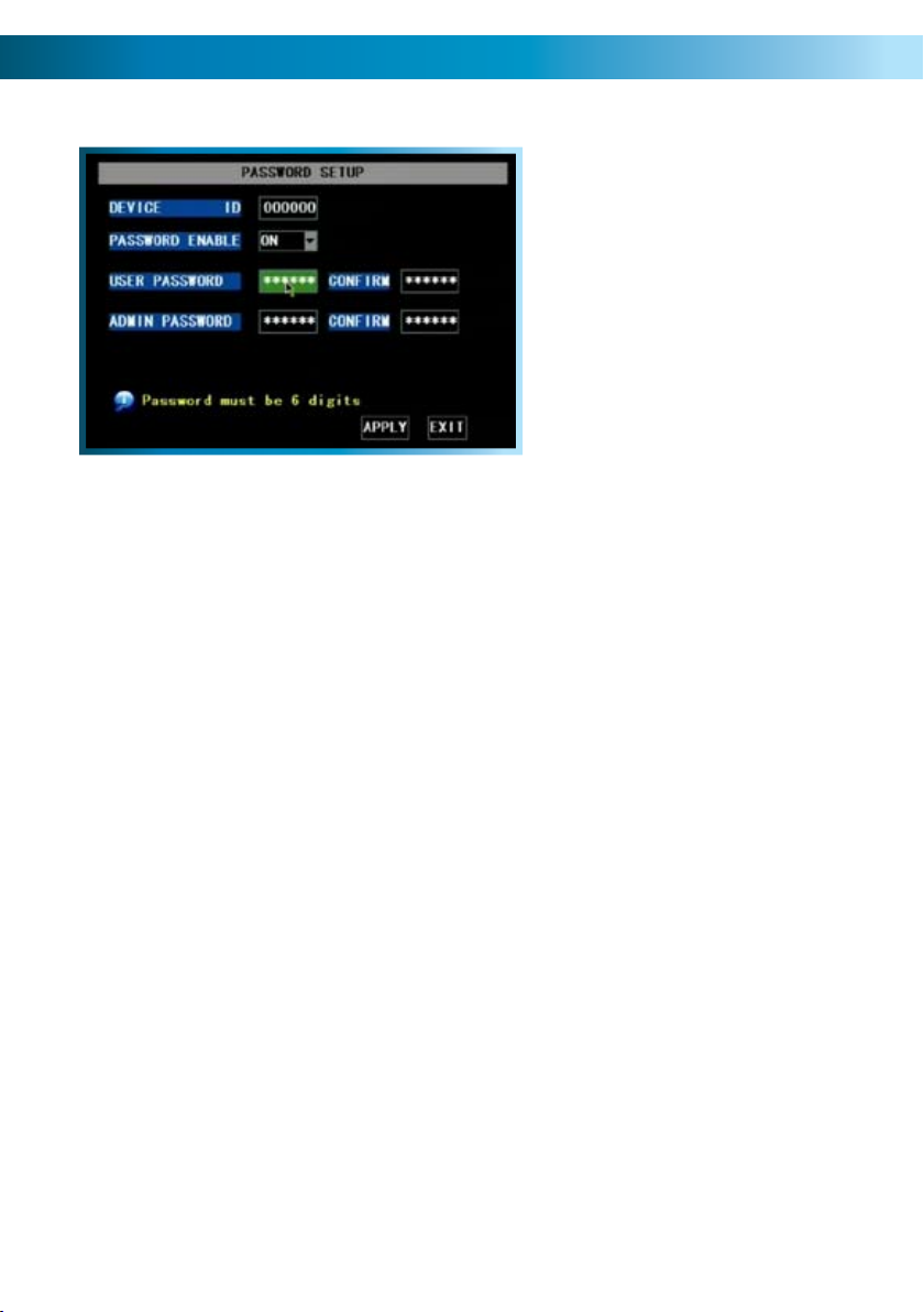
The Password Setup Menu
Setting your Password
The system password allows you to
protect the DVR’s settings & recording.
Without the password the DVR menu
cannot be accessed. We strongly advise
that you set a password as soon as
possible to prevent unauthorized access
to the DVR, either locally or remotely.
It is this same password which must
be entered for remote viewing the first
To set your PASSWORD:
Open the PASSWORD submenu.•
Using the mouse or the arrow buttons, highlight the PASSWORD ENABLE •
drop-down menu, and change the value to ON.
Two new options will pop up: USER PASSWORD and ADMIN PASSWORD.•
The USER PASSWORD will grant access to the DVR and the footage stored on •
it. The ADMIN PASSWORD is required to change settings, the record modes
and schedule, or to change other important aspects of the functionality of the
DVR.
time.
Using the arrow buttons or the mouse, highlight the password field that you •
would like to change.
Using the popup numerical pad which appears, enter the password of your •
choice. It almost goes without saying, but we’re going to say it twice: choose
something you’ll remember!
To protect against a mistake at this point (which would lock you out of your •
DVR) you’ll need to enter the password again in the CONFIRM box immediately
next to the USER or ADMIN PASSWORD field.
NOTE: The default password to the DVR is “123456”. If you lose or forget your
password (thus locking yourself out of the DVR) you’ll need to contact Swann
Technical Support. Our number is on the back of this booklet. However, we strongly
advise that you choose a password you’ll remember! It’ll save grief later...
42
Remember: After making changes to the settings press/click the APPLY button.
Page 43

The Video Setup Menu
The VIDEO SETUP menu allows you to
control the video signals being sent by
VIDEO SYSTEM: Here you can choose between PAL and NTSC. PAL is used in
Western Europe and Australia, NTSC is used in the US, Canada and Japan.
If the DVR’s picture is black and white, flickering or similar, then this is probably
caused by the video system being set incorrectly.
the DVR.
Remember: After making changes to the settings press/click the APPLY button.
43
Page 44

The Language and Info Menus
Language Menu
Using the mouse or the arrow buttons, •
select the drop-down menu of
Choose the language that best suits •
Confirm your choice by pressing select •
A Note on Languages:
Unless you really want to change the language of the DVR menus, stay away from
this setting. Having the menus in a foreign language can make it difficult to get
back to the menu to put the setting back to the right one! Having said that, if you
do change it by mistake (or the DVR is in a foreign language when you get it) in
the main menu, select the icon in the bottom right, then in the SYSTEM menu,
LANGUAGES is the icon in the bottom left. That will bring you to the drop down
menu where you can change languages.
languages.
your needs.
or left clicking the option.
System Information
The system information menu
displays the version of the hardware
and software you are running.
Additionally, this screen will also
display the Media Access Control
(MAC) address.
There is nothing on this screen to set - the System Information menu is for reference
only. Unlike the other networking addresses (such as the IP address and similar) the
MAC address cannot be set.
The most likely reason you’ll need to access this menu is if you are seeking technical
support and we ask you what version of the DVR hardware and software you are
running.
44
Remember: After making changes to the settings press/click the APPLY button.
Page 45
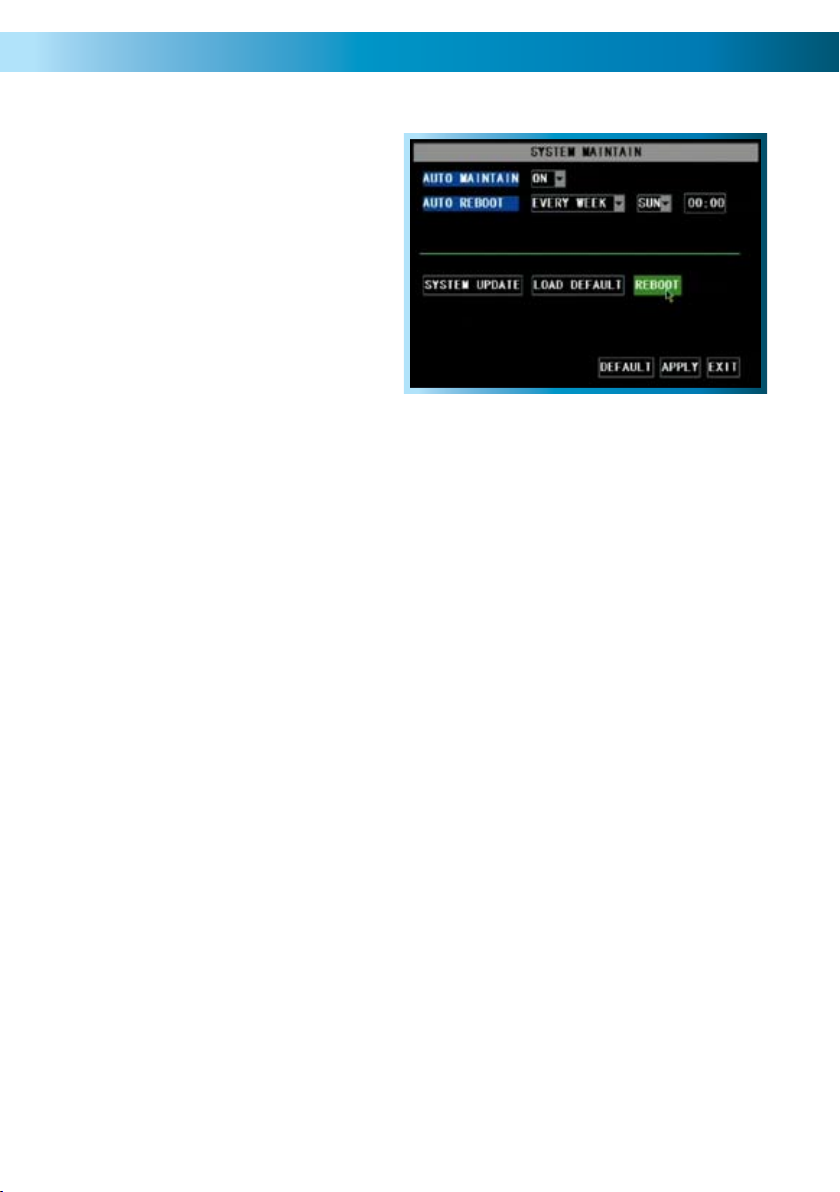
The System Maintenance Menu
To maintain the operational integrity
of the DVR, it is suggested that it
be rebooted periodically. In much
the same way that a computer
can become unstable if left on for
an extremely long time, the DVR
can become unstable. It is strongly
suggested that the DVR be rebooted
at least once per month. However,
as this can be a hassle (particularly if
the DVR is stashed away somewhere
inconvenient) you can set the DVR up
to reboot itself.
AUTO MAINTAIN: Whilst OFF, there won’t be any other options available on this
screen. Turn this ON if you want to set the AUTO REBOOT function.
AUTO REBOOT: Will automatically shut the DVR down and restart it at a certain
time of the day, week or month.
SYSTEM UPDATE: For loading new soft/firmware onto the DVR via a USB flash
drive. Usually, you won’t need to use this setting unless directed to do so by Swann
Technical Support.
LOAD DEFAULT: Returns the DVR to it’s initial factory settings. Can be useful if,
for some unknown reason, the DVR is behaving erratically.
REBOOT: Turns off and restarts the DVR immediately.
About the AUTO REBOOT time:
If you choose weekly rebooting, you’ll need to select the day of the week •
(from MON through SUN) and the time that you’d like the DVR to reboot.
If you chose monthly rebooting, you can choose the date of the month that •
you’d like the DVR to reboot, and then the time on that date.
Note that, if you chose monthly rebooting and you enter the 31st as the date •
you’d like the DVR to reboot, there are several months of the year that don’t
have a 31st day. It is suggested that this date be avoided, for that reason.
When the DVR is rebooted, no settings will be lost, and it will automatically re-•
sume its recording mode and schedule without alteration. The reboot primarily
refreshes the software and gives the hardware a moment of ‘time out’, aiding
the ongoing smooth functionality of the DVR. It will not lose your settings.
Remember: After making changes to the settings press/click the APPLY button.
45
Page 46
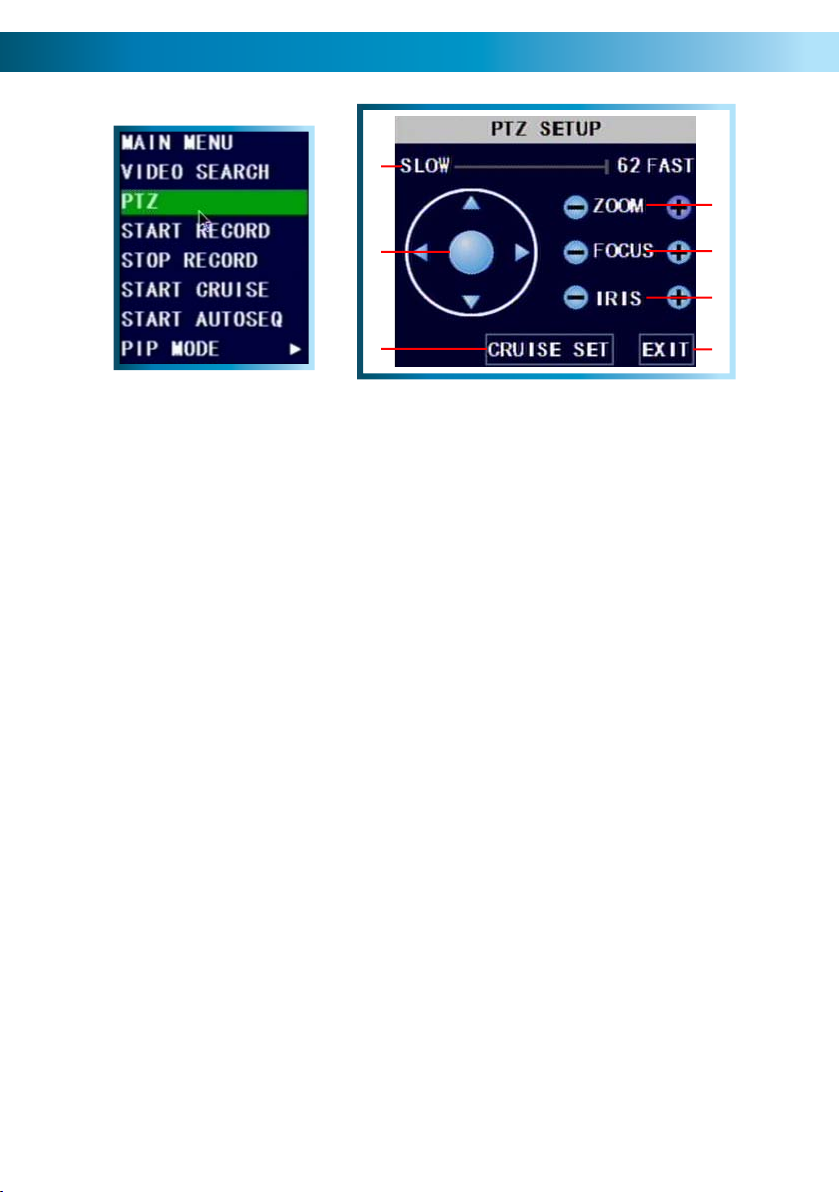
PTZ Controls
1
3
2
6
You can bring up the PTZ Setup window by pressing the PTZ button on the remote
control, or by right-clicking the mouse in the live view mode, and choosing PTZ.
Note: the features which will usable depend on the capabilities and
limitations of your PTZ system.
Here, you’ll be able to aim the camera, as well as alter aspects of the lens and iris
configuration. We’ll explain a little more about what each of these does:
1. SPEED ADJUSTMENT
By selecting this with the mouse or the
arrow buttons, you are able to change
the speed at which your camera will tilt,
pan and zoom. The higher the number,
the faster the camera will move.
2. ARROW BUTTONS
Used to manually move the camera. The
arrow buttons will move the camera in
the selected direction, and the centre
button toggles Auto-Scan ON and OFF.
3. ZOOM
If you are using a variable zoom PTZ
camera, you can zoom in or out here.
Zooming in will increase the size of
objects in view, at the expense of
reducing the field of view. You may
need to adjust focus when using the
ZOOM function.
Adjusts the focal plane of the lens.
If an image is blurry, try adjusting the
focus. To best set the focus, move one
direction until things become clear, and
then blurry again. Move back and forth
until you find sharp focus.
Controls how much light gets into the
camera. If things look too bright (or
white) lower the IRIS value. If things are
too dark (or black) raise the IRIS value.
Many cameras do this automatically.
Open the CRUISE SETUP window, see
next page.
Leaves the PTZ SETUP menu.
4. FOCUS
5. IRIS
6. CRUISE SET
7.EXIT
4
5
7
46
Remember: After making changes to the settings press/click the APPLY button.
Page 47
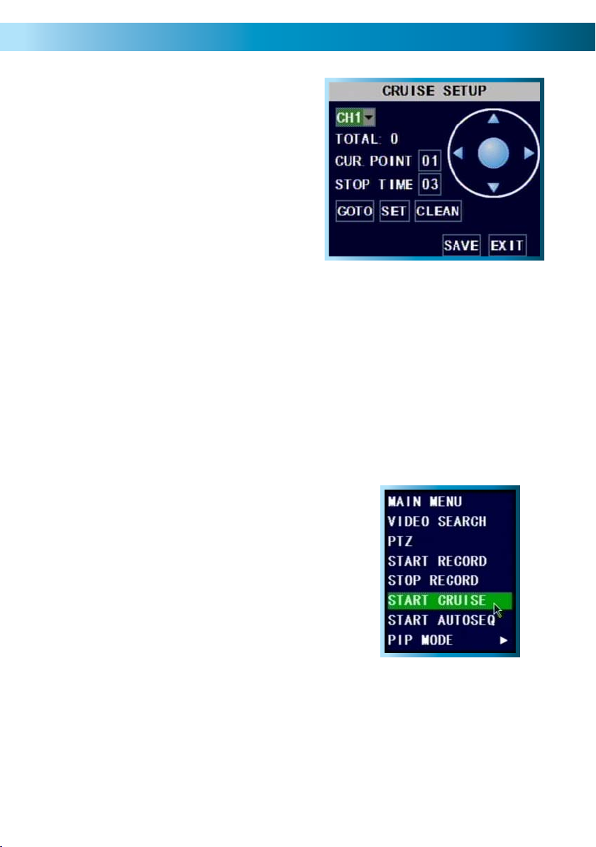
Cruise Mode
To setup CRUISE MODE, you’ll need to
define “POINTS” for each channel with
a PTZ camera you want to “cruise”.
A POINT is one place that the camera
needs to move to on its loop.
Move the camera to the desired position using the arrows.•
Hit the SET button.•
The point will be saved. Its name will be one digit higher than the previous •
point.
For easy cruise setup, define your points in the same order as you want the •
camera to move through them.
The GOTO button will take the camera back to a predefined point. The CLEAN
button will remove all your defined points.
When you’ve set your points, select SAVE, then EXIT.
To start cruise mode, select START CRUISE from •
the pop-up menu.
To stop cruise mode, select STOP CRUISE form •
the same menu.
Remember: After making changes to the settings press/click the APPLY button.
47
Page 48

Requirements for Remote Access
The primary requirements for accessing the DVR4-2000 via the Internet are:
A High-Speed Internet Connection
Video uses a lot of data, so you’ll need a fast Internet connection in order to get
smooth playback and monitoring remotely. Note that upload speed refers to the
rate at which an Internet connection can send data, not receive it. Most Internet
plans are ‘asymmetrical’, which means they can download data faster than they
can upload it.
We think that an Internet connection with an upload speed of 256kpbs is generally
sufficient for remote access, but ideally upload speeds of 512kbps or higher are
recommended - particularly for multi-channel playback or monitoring at higher
resolutions and quality settings.
Your DVR & Local Network Correctly Configured
It is important that your home network function correctly, and that the information
entered into the Networking menu in the DVR (see page 22) matches the general
network settings.
The first thing you’ll need to determine is whether your router requires devices to
use fixed (STATIC) or dynamic (DHCP) addressing - you’ll need to the documentation
which came with your router to learn which type of IP allocation your router
requires. Most of the time, routers support both allocation methods. In such cases,
we suggest using a STATIC configuration, as it will let you exercise more control
over the functionality of your network, and reduce the need for maintenance.
In a DHCP configuration, you do not need to enter the IP address, subnet mask or
default gateway values into the DVR. Rather, the DVR will automatically request
this information from your networks Dynamic Host (usually your router).
Finding your Network Information
You may be wondering how to find information, such as your Subnet Mask,
Gateway values and DNS servers, as well as the first three parts of the IP address
you’ll need to assign the DVR. To do so from a Microsoft Windows® based PC:
Open the • Start Menu.
In the • Search Box/Run Box (depending on the version) enter “command”
and press Enter.
An imitation DOS prompt will appear. Type “• IPCONFIG /ALL”.
All the relevant information will then be displayed on-screen. •
48
Page 49

For a STATIC configuration, the DVR needs to be told what IP address to use (this
must be unique) and the subnet mask, gateway address and DNS server address
(these must match the other devices on your network).
The most common way of discovering these values is to use a computer already
connected to the network, which can access the Internet. Typically, this is a matter
of bringing up the Properties window for your local area connection (LAN).
Depending on your operating system, there are different ways to do this.
Once you’ve found the network settings on your computer:
Set the • gateway, subnet mask and DNS server addresses to match those
that your computer uses.
For the IP address, the first three groups of numbers should be the same, with •
the last being different (unique). For example, if your computer’s IP address was
“192.168.1.12” then you could set the DVR’s IP address to “192.168.1.235”.
(The choice of “235” is somewhat arbitrary - it can be anything between 0
and 255, so long as no other device on your network is using that address. We
suggest 235 as it is usually available.)
Port Configuration
The DVR4-2000 needs two “ports” to be available and properly configured to
work correctly over the Internet. One of these is called the “Media Port” and the
other is called the “Web Port”.
Media Port: The default value is “9000”.
Web Port: The default value is “80” - we strongly suggest changing this as “80”
is a port frequently used by various programs (in fact, it’s the default HTTP port).
Generally, “85” is a much better choice - however, you can set this to be anything
that you want, just be sure to remember it! You’ll need it later.
Remember: these ports need to be forwarded from your router directly to the
DVR. Without these ports forwarded properly, remote access will be slow and
playback will be jerky - if it works at all.
49
Page 50

Setting Up Remote Access
Public and Private IP Addresses
The IP address used by the DVR, whether entered manually (STATIC) or assigned
by the dynamic host (DHCP) is the private IP address of the DVR. The private IP
address is used to locate the DVR on your private network. However, to access
the DVR from a remote location via the Internet, you’ll need to know your home
networks public IP address.
What’s the difference?
The IP addressing system that the Internet utilizes at the moment supports up
to (approximately) 4 billion addresses. That is a lot, but it’s not enough for every
device connected to it (computers, phones, video game consoles, DVRs, servers,
televisions and even some refrigerators can all have Internet connections) to have
individual addresses. This problem is solved by assigning an address to each subnetwork on the Internet. This means that all LANs, such as your local network in
your home or office, will have a public IP address which will allow you to find that
network from anywhere connected to the Internet.
This means that all devices connected to your network share one public IP address.
To differentiate devices on your network, your network has its own IP address
range, and this is what is referred to as your private IP address. The private IP
address is used to configure your DVR and router for remote access through a
process known as Port Forwarding.
How do I find these addresses, and what should I do with them?
If you’ve configured your network using STATIC IP addressing, then you’ll be
entering the private IP address directly into the DVR. Then you’ll need to choose
your Web Port and Media Port. Finally, you’ll have to configure your router to
forward your selected ports to the private IP address of the DVR.
If you’re setting up a dynamic network (DHCP) then you don’t need to know the
private IP address of your DVR (it’ll probably change over time, anyway). Rather,
you only need to define the Media Port and Web Port, then configure your router
to forward these ports to the DVR (usually your router will have a drop-down menu
allowing you to select which devices on the network to forward ports to).
Finally, to learn your networks public IP address, you’ll need a computer with Internet
access connected via the same network as the DVR you’re configuring. Then, open
an Internet browser window. In the address bar, go to www.whatismyip.com. Your
public IP address will be displayed instantly!
50
Page 51
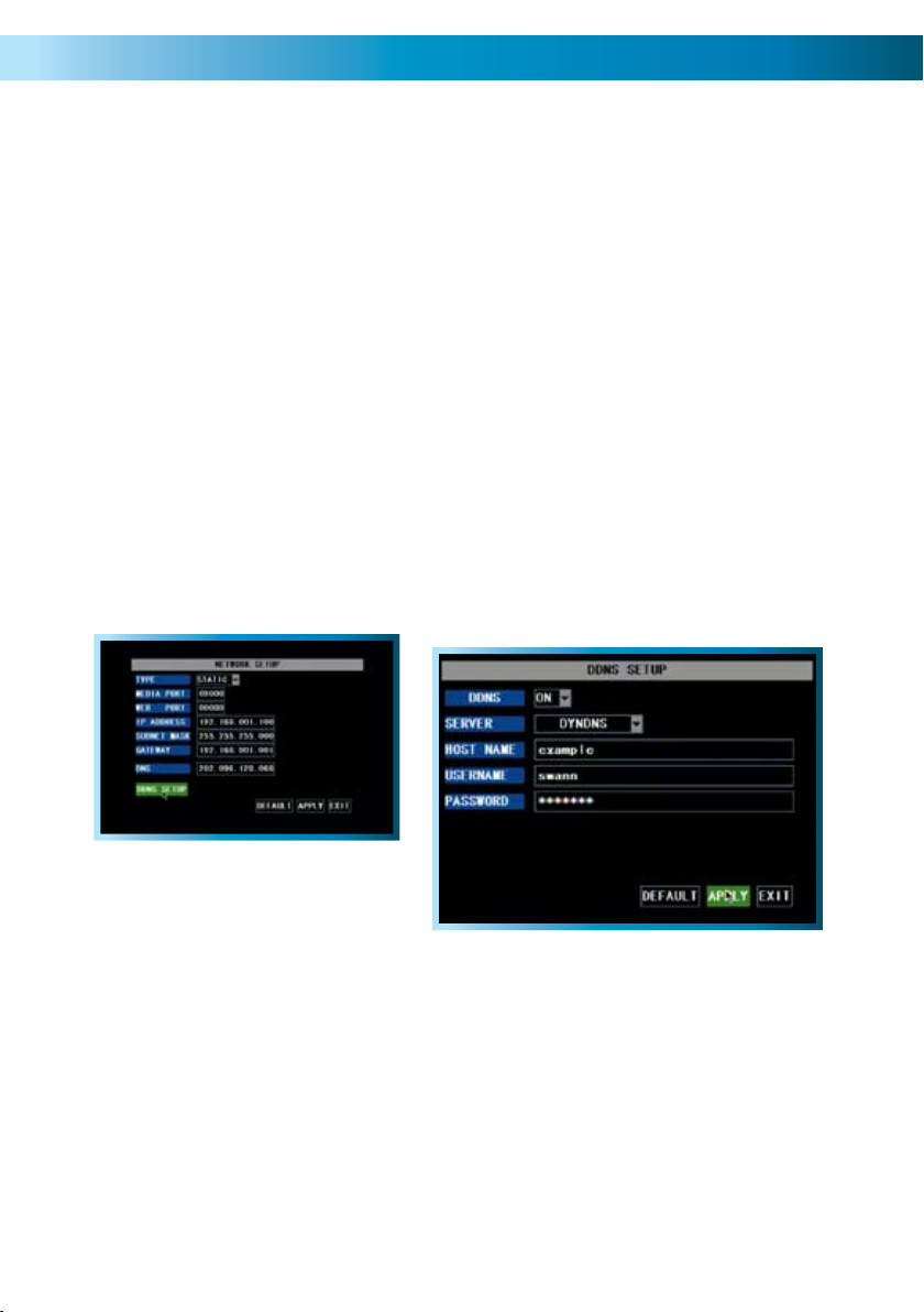
Static and Dynamic IP Addresses
In much the same way as your home network can use static or dynamic IP addresses,
many Internet providers don’t issue (or charge more for) a static IP address for users.
The easiest way to find out is to contact your Internet service provider. Alternately,
you can access the www.whatismyip.com service, make a note of your IP, then
reboot your router/gateway. This should refresh your Internet connection. If your
IP address stays the same, you’ve probably got a static IP address. If it changes, you
have a dynamic IP address.
How do I deal with a dynamic IP address?
One option is to contact your ISP and request a static IP address. They’ll usually
charge a small fee for doing this. It’s worth noting that not all ISPs offer static IP
addresses.
If your ISP does not offer static IP addresses then you can use a dynamic referencing
service, like www.dyndns.com. They offer a free service which will give you a text
address (such as www.exampleipaddress.example) which will take you directly to
your public IP address. For this service to work correctly, you’ll need to set up the
DVR to work with DDNS.
Above: The DDNS Setup button, located in
the Network Setup menu.
Right: The DDNS Setup menu.
Server: Choose the server that you’re using. There are two options, DYNDNS
(www.dyndns.com) and 3322 (www.3322.org). We suggest DYNDNS, unless you
are fluent at reading Chinese.
Host Name: Enter the host name that you set up in your DDNS service. This is the
address you use to access your network.
Username and Password: Here, enter the username and password you setup
with your DDNS server. These do not have to match your username/password
combination in either your DVR or router (for the sake of security, we suggest
making them different).
Remember: After making changes to the settings press/click the APPLY button.
51
Page 52

Remote Access via Internet Explorer
The easiest way to access your DVR remotely is via an Internet browser. These
instructions will detail how to access the DVR via Microsoft Internet Explorer®.
This section assumes that you’ve already configured the DVR and your network to
operate properly. Remotely accessing the DVR via Internet Explorer (IE) is a great
way to test if your network is functioning as it should.
Note: You may have to alter and configure the ActiveX controls in IE to allow
unrestricted access to the DVR. Access might be slowed or blocked completely by
IE’s built-in security functions. The instructions on how to do this are covered on
the next page.
To access the DVR remotely via Internet Explorer:
Open an 1. Internet Explorer window. If you do not have Internet Explorer you
can download it from the Microsoft website (www.microsoft.com).
In the address bar type “http://” followed by your 2. public IP address, a colon
then your web port. For example, if your web port is “85” and your public IP
address is “210.9.10.115”, then you’ll need to enter:
You will now see a login window. Here, enter your password. If no password 3.
is set, leave this dialog box blank.
You should now have access to the DVR. 4.
52
http://210.9.10.115:85
Page 53
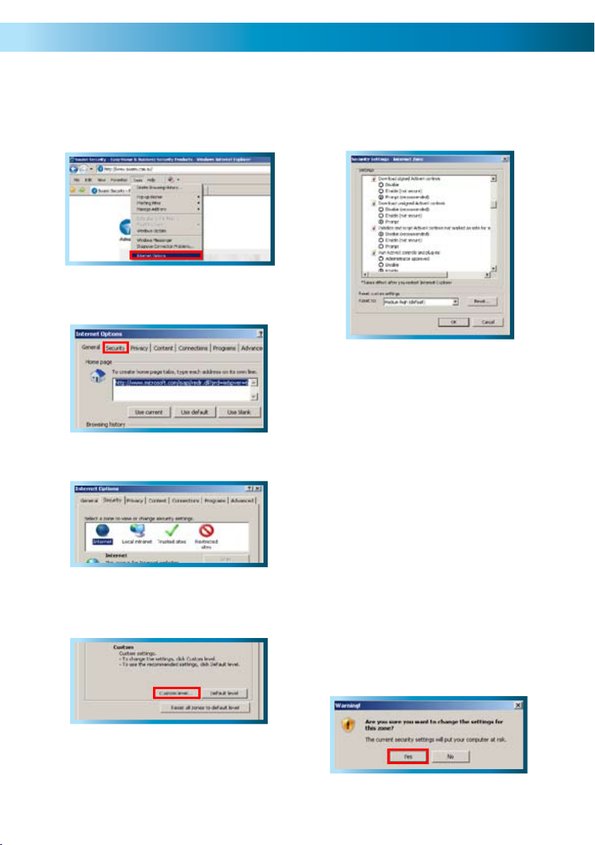
Adjusting the Security Settings in Internet Explorer
Open 1. Internet Explorer.
Click 2. Tools --> Internet Options.
In 3. Internet Options click on the
Security tab at the top.
You will now see the list below (or 6.
similar, depending on the version of IE
you are running).
Set 7. Download signed ActiveX
controls to Prompt.
Set 8. Download unsigned ActiveX
controls to Prompt.
Select the INTERNET zone option.4.
Click on the CUSTOM LEVEL button.5.
Set 9. Initialize and script ActiveX
controls not marked as safe for
scripting to Prompt.
Set 10. Run ActiveX controls and plugins to Enabled.
Set 11. Script ActiveX controls marked
safe for scripting to Enabled.
After you have made these changes, 12.
click Okay.
You will be asked to confirm your 13.
changes. Choose Yes.
53
Page 54

Remote Access from a Mobile Device
The DVR4-2000 supports access from mobile devices, such as mobile phones with
Microsoft Windows Mobile® as their operating system, as well as the increasingly
popular iPhone. To correctly configure your DVR for remote access via a mobile
device, or indeed any remote access, it is important to have your network and
Internet connection configured correctly. Typically, this is a matter of forwarding
ports from your router to specific devices (in this case, your DVR).
Setting up the DVR for Mobile Access
Enter the 1. Main Menu.
Navigate to 2. Devices.
Select 3. Mobile.
Enter a 4. USERNAME and PASSWORD for mobile access. This may be the
same or different to your regular password, depending on your security needs.
We suggest using a different password for mobile access, but something that
you’ll remember.
Choose a 5. PORT for remote access. This port will need to be properly forwarded
from your router to ensure maximum bandwidth for sending footage.
Accessing the DVR4-2000 via an iPhone
Go to the 1. iTunes Store, and search for an application called APlayer.
Download and install this app.2.
Run 3. APlayer.
Press the 4. button.
In the space provided, enter the 5. public IP address of your DVR.
In the next space, enter the 6. mobile port number.
Finally, enter your 7. username and password and choose to connect.
54
Left: The main viewing
interface of APlayer.
The IP address shown at
the top of the screen is
the public IP address of
the network to which
the DVR being accessed
is attached. Images are
displayed in the window
below, and the viewing
controls are located
across the bottom of the
screen.
Right: The Settings screen,
where you can enter
the address and user
information for your
DVR.
Page 55

Accessing the DVR4-2000 from a Mobile device running Windows Mobile
You’ll need the mini-CD which came with the DVR4-2000, as that contains the software
you’ll need to install on the Microsoft Windows Mobile
®
based device.
Insert the mini-CD into your computer.1.
Attach your mobile device to your computer. Depending on your specific mobile 2.
device, it may be connected via USB, Bluetooth, FireWire or other method. If you’re
unsure, consult your mobile device manufacturer’s documentation.
Locate the file on the mini-CD called 3. AMPLAYERSETUP.EXE. It is located in the folder
called Mobile ActiveX Windows.
Copy 4. AMPLAYERSETUP.EXE to the PROGRAMS folder on your mobile device.
Disconnect the mobile device from your computer. Remember to use the 5. Safely Remove
Hardware option, if applicable.
Using your mobile device, execute the 6. AMPLAYERSETUP.EXE file. Follow the prompts
to complete the installation.
Once installation is complete, open the 7. Start Menu.
Run the program called 8. QQeye.
Click the button labeled 9. Setting located near the top of the main interface.
Left: The main viewing interface of
QQEye. The viewing controls
are located across the bottom
of the screen.
Right: The Settings screen, where
you can enter the address
and user information for
your DVR.
10. Here, you’ll need to enter the relevant information for connecting to your DVR.
These are:
Your • username and password. Specifically, these are the ones
entered in the Setting up the DVR for Mobile Access above.
Server address• . If your ISP provides static IP addresses, then the
server address you’ll need is your public IP address.
The • port that the DVR has been configured to use for mobile access.
Again, this is the port that you selected in the Mobile Device setup
on the DVR.
Choose a channel• from 1 through 4 – as mobile devices have
limited bandwidth, the DVR4-2000 will only stream one channel at
a time. To choose another channel, reconnect. As the software is
designed to function with multiple DVR systems, it will display up to
16 channels, only four of which will interface with the DVR4-2000.
11. Then, click .
12. Standard playback controls and PTZ features (if applicable) are located across the
bottom of the playback window.
55
Page 56

NetViewer - About the Software
The included software “NetViewer” is an invaluable tool for accessing, operating,
controlling and backing up footage from your DVR. It interfaces with your DVR via
your local network or remotely via the Internet, so it’s also the primary method of
remotely accessing your DVR as well. The software can be installed on as many
computers as you like.
Using the NetViewer software, you’ll be able to remotely:
View live images coming from the DVR.•
Playback and backup events from the DVR hard drive directly to the remote •
terminal you are accessing the DVR from.
Change the settings and preferences in the DVR menu system (such as the •
recording schedule and quality settings).
System Requirements
Minimum Recommended
Processor 1.0 GHz or more 2.0 GHz or Dual/Quad Core
RAM 256MB 512MB or higher
Graphics Card 64MB 128MB or higher
Screen Resolution 1024 x 768 1280 x 1024 or higher
Internet Connection 128kbps upload speed 256kbps upload speed or higher
Operating System(s) Microsoft Windows® XP 32-bit
Microsoft Windows® Vista 32-bit or 64-bit
Microsoft Windows® 7 32-bit or 64-bit
Notes:
We suggest ensuring that your network is functioning properly before installing •
this software - you can test remotely accessing your DVR via an Internet
browser window.
At the time of writing, the software does not support the newer 64-bit versions •
of these operating systems.
The NetViewer software is not compatible with Mac OS or Unix/Linux •
systems.
Microsoft Windows is a registered trademark of Microsoft Corporation in the United States and other countries.
56
Page 57
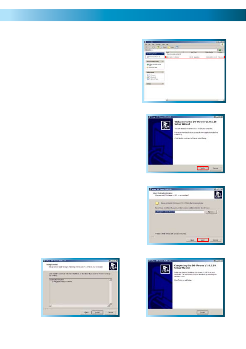
NetViewer - Installation Guide
Insert the mini CD-ROM which came with 1.
your DVR into your computer. Most CD/
DVD/Blu-Ray trays have a small, inner
groove which takes mini CD-ROMs. If your
CD/DVD/Blu-Ray drive does not support the
mini CD-ROM standard (such as a laptop
with a slot-loading drive) then we suggest
using another computer to open the CD,
and copying the file to a USB flash drive. It’s
a very small program, and it can be copied
easily without affecting its performance.
Locate the file on the CD-ROM labeled 2.
“Net-VIEWER-DBG-ENG.EXE” and run
this file. If prompted for permission to run
the file, choose “Yes” or “Continue” as
applicable.
You’ll see a dialog box informing you that 3.
you should close all other programs and
applications. Once all other applications are
closed, click “Next”.
You will be asked to choose the location on 4.
your hard drive where the NetViewer will
be installed. Unless you have specific plans
for the organization of your hard drive, the
default location is fine.
Again, you’ll be asked to confirm your 5.
choices. Choose next.
The final window will inform you that 6.
installation has been completed successfully.
Simply click Finish to quit the installer.
Step 2
Step 3
Step 4
Step 5
Step 6
57
Page 58

NetViewer - Starting the Software
Before starting the NetViewer software, ensure that the DVR is properly connected
to your network. The computer you use to open the software should also be
connected the network or the Internet so that it can communicate with the DVR.
To open NetViewer:
On your PC click on START •
--> ALL PROGRAMS
Find the Net-VIEWER •
folder.
You’ll be taken directly to the login screen, where you’ll need to tell the NetViewer
software where it can find your DVR, and the password so it can be accessed. To
do this:
Enter the relevant IP address of •
your DVR. If the DVR is on the
same network as the PC you’re
using to access it, then you should
use the private IP address. If you’re
connecting via the Internet, you’ll
need to use the public IP address
of the DVR. See page 50 for more
information about public and
private IP addresses.
210.9.10.115
00085
Enter the number of the Media Port. This should be the same one that you set •
in the DVR. This port will also have to be forwarded from your router otherwise
your bandwidth will be limited or the connection will not work at all.
Enter your password. If you have not set a password, then it will be the default •
“123456”. If you have disabled all password protection (we advise strongly
against doing so, but it’s up to you), then leave this field blank.
Finally, choose whether you’re connecting to the DVR via a local network (LAN) •
or via the Internet. This will alter, amongst other things, the amount of data
the DVR tries to send to your PC - a local network can handle a much higher
amount of data being transferred than the Internet.
Click on LOGIN to open communication with the DVR. •
Once you’ve logged in, you will be taken directly to the main user interface of •
NetViewer.
58
Page 59

NetViewer - The Main Interface
1
3 4 5 6
2
27
Channel Name1.
Date & Time2.
Live - Click to view live view screen.3.
Replay - Click to view the replay screen.4.
Setup - Click to view the setup screen.5.
Logout - Click to logout.6.
Minimise - Press to minimise screen7.
Close - Press to close Net-Viewer.8.
PTZ Control - Pan, Tilt, Zoom 9.
controls.
8
7
9
10
12
13
Open Window, Capture & Record10.
Click to OPEN and CLOSE live view .
Click to capture image.
Click to start recording.
Single, Quad View Buttons11.
Click to view single camera view.
Click to to view quad view.
Volume Bar - LEFT click and drag 12.
mouse from left to right to increase
the DVR volume.
Mute - Click to mute sound.13.
11
59
Page 60
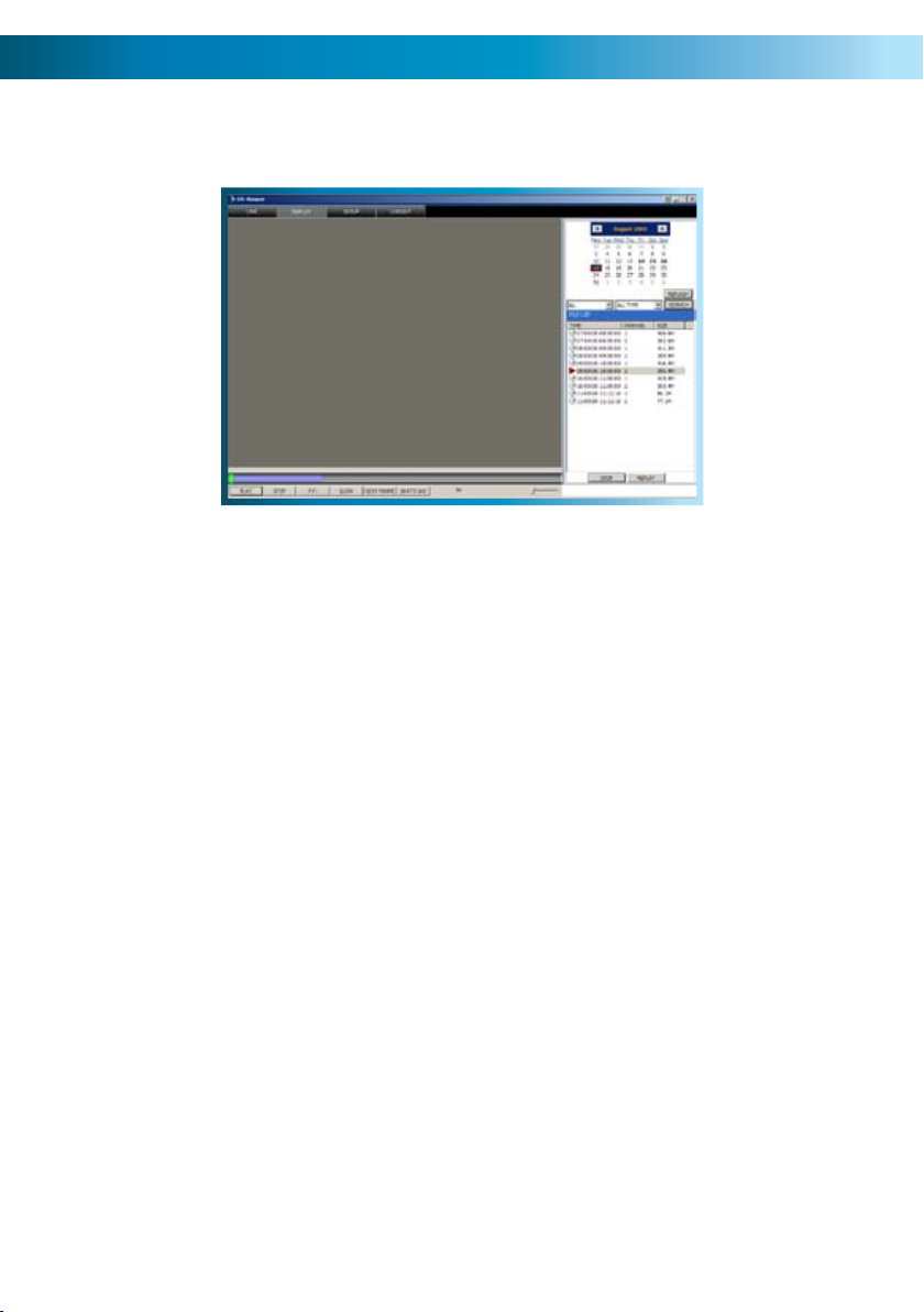
NetViewer - The Replay Interface
The REPLAY screen allows you to remotely access, playback and backup recordings
from the DVR remotely. When backing up in this manner, the file will be saved
directly to the computer you’re accessing the DVR from.
Locate the calender, located in the 1.
upper right hand corner of the
screen.
Click on the date you wish to access 2.
an event from.
Below the calender, there are two 3.
drop down menus.
The first (left) drop-down menu 4.
selects which channel(s) you want.
Playback Controls
Play: Begins playback of the selected event.
Stop: Ends playback.
F.F. (Fast Forward): Increases speed of playback. Press multiple times to further
increase playback speed.
Slow: Reduces the speed of playback. Press multiple times to
further reduce the playback speed.
Next Frame: Moves the video forward by the smallest increment possible,
a single frame.
264 to AVI: Exports the currently selected event as a stand-alone video
file that can be played by most computers without dedicated
software. A great backup tool, particularly if you need to
send or share footage with others.
60
The second (right) drop-down 5.
menu chooses the recording mode
you’d like to see events for.
Any event which was recorded on 6.
your selected channel(s) in your
selected recording mode on the
day you’ve selected will be shown
as a chronological list in the small
window located below. Simply
choose the event you want to
playback from this list.
Page 61
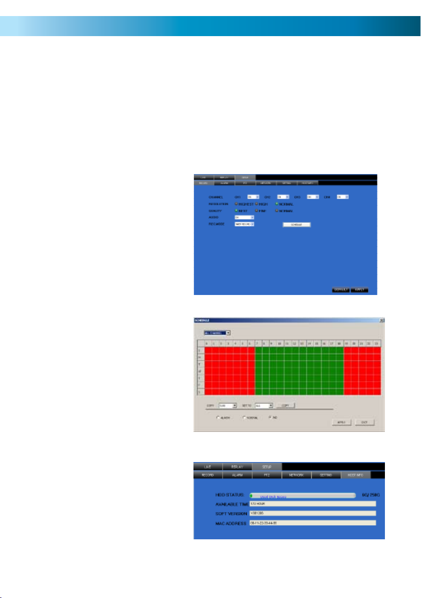
NetViewer - Setup
In the SETUP you can change the camera record settings. You can turn each channel
on or off, select the recording resolution & quality, turn on or off the audio, select
a record mode and set up the record schedule. Note that you must be logged in
using the ADMINISTRATOR password to be able to change options.
Most of the options that you will find here operate in exactly the same manner
as on your DVR. However, as this software can be used to control a few different
models of DVR, occasionally an option will be displayed which has no effect on your
DVR. Don’t worry about these settings - they won’t interfere with the operation
of your DVR.
Setup: Record
Here you’ll find the same options
as the Record Options menu in the
DVR. You can change the resolution
and quality settings, enable and
disable audio as well as change the
record mode for each channel.
Also accessible from here is the
RECORDING SCHEDULE, which
operates and can be edited in the
same way as the schedule in the
DVR.
Setup: Host Info
Here you’ll be able to find
information about your setup.
You’ll be able to see how much
space remains on your hard drive,
represented in both GB remaining
and hours of footage at your current
record settings. Also, if you need to
know what version of the software
you’re running, this screen will tell
you. Finally, the MAC Address of the
DVR is also found here, if required.
61
Page 62

NetViewer - Setup (continued)
Setup: Alarm
Here you’ll find the same options as in
the Alarm Menu in the DVR. These can be
customized in the same manner as they
would be from the menu on the DVR itself.
You can access the motion detection area
definition screen from the ALARM menu.
This works in the same manner as the same
screen within the DVR menu. The red squares
indicates the area which will be sensitive to
motion.
Setup: Network
Here you can change the network settings for
the DVR in the same manner as the Network
menu in the DVR itself (see pages 22 & 23 for
more details). You will need to restart both
the DVR and the NetViewer software after
making any dramatic changes. Remember to
update your login information if you change
the ports numbers or IP address of the DVR.
62
Setup: Setting
Here you’ll be able to change the settings for
NetViewer. You can alter:
The location on your PC where any •
footage you back up will be stored.
The speed at which your network or •
Internet connection can upload data.
Setting this properly will give you the
best quality video possible without
overloading your connection.
Your passwords. You’ll need to be logged •
in as an administrator (as opposed to a
user) to change this.
You can also turn automatic adjustments •
for daylight savings time on or off.
Page 63
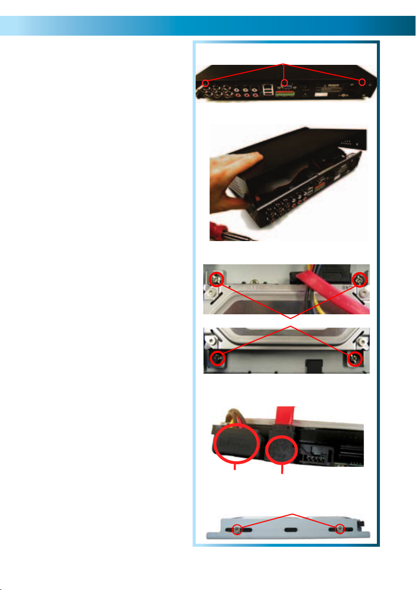
Installing/Changing the HDD
Note: the following instructions are
for installing or changing the hard
drive. If your DVR already has a hard
drive pre-installed, and you don’t want
to change it, disregard these steps.
Ensure the DVR is switched off 1.
and unplugged from mains
power.
Locate and remove the 3 screws 2.
on the rear of the DVR.
Pull up the top case of the DVR. 3.
Locate the 4 screws holding 4.
down the hard drive chassis.
Remove these screws and
remove the chassis from the
DVR.
Push the metal clip on the SATA 5.
cable (single red or orange cable)
to unplug the cable from the
hard drive. Unplug the power
cable (2 black, 1 yellow, and 1
red cable) from the back of the
hard drive.
2
Remove
Back of DVR
3
4
Remove
Four screws secure the hard drive 6.
to the drive chassis. Remove
these.
If replacing the hard drive, put the 7.
new hard drive into the chassis.
Screw in the hard drive to 8.
chassis as in step 5, and attach
the chassis to the DVR case as
in step 4.
Replace the top of the case.9.
Screw in the remaining screws 10.
to the sides and back of the DVR
as in step 2.
5
Power Cable
6
SATA Cable
Remove
63
Page 64

Troubleshooting
Problem: My monitor is not showing any display/picture.
Solution: Make sure you have connected the VIDEO OUTPUT on the DVR to a
VIDEO INPUT on the back of your TV/monitor. Try different channels on your TV or
monitor - many TV’s call their component video input confusing things, like AV, TV/
AV, AUX, COMPOSITE, CHANNEL 0 and so on.
Problem: My DVR does not switch on.
Solution: Make sure you have plugged in the power supply (12V 3A) to the DVR
and into the wall socket. Carefully check the integrity of the connections. Check
the master switch on the back of the unit. Try another power socket.
Problem: My display is showing “NO HARD DISK” when I press record.
Solution: If you have recently changed the hard drive in your DVR unit make sure
it is plugged in properly; otherwise the hard drive may be faulty. Try connecting
another (working) hard drive to the DVR; if this still doesn’t work then the DVR
maybe faulty. We suggest calling Swann Technical Support - the contact information
is on the rear cover of this booklet.
Problem: I am not getting a picture on any of my displays.
Solution: Make sure the cameras are connected properly to the DVR and the
power supply (12V 1A). Check that the cables are not faulty by connecting the
cameras directly to the DVR or to a TV (if you have the proper adapters).
Problem: One of the displays is not showing on my screen.
Solution: Make sure all cameras are set to ON in CAMERA SETUP. Check the
integrity of your cables and connections. Check the power supply to the camera.
Try attaching another channel to the questionable input.
Problem: I cannot login to my DVR remotely using the NetViewer software or the
Internet Explorer browser.
Solution: Make sure you have configured the IP, ActiveX and USER SETUP correctly.
Remember the USER PASSWORD may be different to the ADMIN PASSWORD. The
ADMIN PASSWORD is used to login to the DVR remotely.
Problem: I cannot perform a backup.
Solution: Make sure the DVR is connected to a USB flash drive, and that the USB
flash drive is formatted to have a FAT32 file system.
64
Page 65

Technical Specifications
DVR4-2000
Video
Video Format PAL or NTSC
Video Inputs 4 x Composite BNC Inputs
Video Outputs 2 x Composite BNC Outputs
Display Resolution NTSC: 704 x 480, PAL: 704 x 576
Display Frame Rate NTSC: 120fps, PAL: 100fps
Audio
Audio Inputs 1 x RCA Audio Input
Audio Output 1 x RCA Audio Output
Recording
Compression Format H.264
Recording Resolution NTSC: D1 (704x480), HD1 (704x240), CIF (352x240)
PAL: D1 (704 x 576), HD1 (704 x 288), CIF (352 x 288)
Recording Frame Rate NTSC: 30fps D1, 60fps HD1, 120fps CIF
PAL: 25fps D1, 50fps HD1, 100fps CIF
Recording Modes Manual / Motion / Schedule / Sensor
Multiplex Operation Triplex
HDD Interface SATA
Hard Drive Support Up to 1TB
Network
LAN Connection Yes
Network Interface Cat5 (8P8C)
Network Protocol(s) TCP/IP. DDNS
Remote Operation Yes
General
Operating Power DC 12V
Dimensions 12.4” x 8.9” x 2.4”
Weight 4.lbs / 2Kg
Backup Method USB to Flash Drive
Mouse Support 1 x USB
Remote Control 1 x InfraRed Controller
Remote Battery Type 2 x AAA
65
Page 66

Notes
____________________________________________________________________
____________________________________________________________________
____________________________________________________________________
____________________________________________________________________
____________________________________________________________________
____________________________________________________________________
____________________________________________________________________
____________________________________________________________________
____________________________________________________________________
____________________________________________________________________
____________________________________________________________________
____________________________________________________________________
____________________________________________________________________
____________________________________________________________________
____________________________________________________________________
____________________________________________________________________
____________________________________________________________________
____________________________________________________________________
____________________________________________________________________
____________________________________________________________________
____________________________________________________________________
____________________________________________________________________
____________________________________________________________________
____________________________________________________________________
____________________________________________________________________
____________________________________________________________________
____________________________________________________________________
____________________________________________________________________
____________________________________________________________________
____________________________________________________________________
____________________________________________________________________
____________________________________________________________________
____________________________________________________________________
____________________________________________________________________
____________________________________________________________________
____________________________________________________________________
____________________________________________________________________
____________________________________________________________________
____________________________________________________________________
____________________________________________________________________
____________________________________________________________________
____________________________________________________________________
66
Page 67

Warranty Information
Swann Communications USA
Inc.
12636 Clark Street
Santa Fe Springs CA 90670
USA
Swann Communications PTY.
LTD. Building 4, 650 Church
Street,
Richmond, Victoria 3121
Australia
Swann Communications LTD.
Stag Gates House
63/64 The Avenue
SO171XS
United Kingdom
Limited Warranty Terms & Conditions
Swann Communications warrants this product against defects in workmanship
and material for a period of one (1) year from it’s original purchase date. You must
present your receipt as proof of date of purchase for warranty validation. Any unit
which proves defective during the stated period will be repaired without charge
for parts or labour or replaced at the sole discretion of Swann. The end user is
responsible for all freight charges incurred to send the product to Swann’s repair
centres. The end user is responsible for all shipping costs incurred when shipping
from and to any country other than the country of origin.
The warranty does not cover any incidental, accidental or consequential damages
arising from the use of or the inability to use this product. Any costs associated with
the fitting or removal of this product by a tradesman or other person or any other
costs associated with its use are the responsibility of the end user. This warranty
applies to the original purchaser of the product only and is not transferable to any
third party. Unauthorized end user or third party modifications to any component
or evidence of misuse or abuse of the device will render all warranties void.
By law some countries do not allow limitations on certain exclusions in this warranty.
Where applicable by local laws, regulations and legal rights will take precedence.
67
Page 68

Swann Technical Support
All Countries E-mail: tech@swannsecurity.com
Telephone Helpdesk
AUSTRALIA toll free
USA toll free
1-800-627-2799
(Su, 2pm-10pm US PT)
(M-Th, 6am-10pm US PT)
(F 6am-2pm US PT)
USA Exchange & Repairs
1-800-627-2799 (Option 1)
(M-F, 9am-5pm US PT)
See http://www.worldtimeserver.com for information on time zones and the
current time in Melbourne, Australia compared to your local time.
1300 138 324
(M 9am-5pm AUS ET)
(Tu-F 1am-5pm AUS ET)
(Sa 1am-9am AUS ET)
NEW ZEALAND toll free
0800 479 266
UK
0203 027 0979
© Swann Communications 2010
 Loading...