

Swann Digital Video Recorder, DVR16-4000 User Manual
English
1
M4-8000H051212E
English
4ch 1080p SDI
Digital Video Recorder

English
2
Introduction
Before You Begin
FCC Verication
NOTE: This equipment has been tested and found to comply with the limits for Class B digital device, pursuant to part 15 of the
FCC Rules. These limits are designed to provide reasonable protection against harmful interference in a residential installation.
This equipment generates, uses and can radiate radio frequency energy and, if not installed and used in accordance with
the instructions, may cause harmful interference to radio or television reception, which can be determined by turning the
equipment o and on, the user is encouraged to try to correct the interference by one or more of the following measures:
• Reorient or relocate the receiving antenna
• Increase the separation between the equipment and the receiver
• Connect the equipment into an outlet on a circuit dierent from that to which the receiver is connected
• Consult the dealer or an experienced radio/TV technician for help
These devices comply with part 15 of the FCC Rules. Operation is subject to the following two conditions:
• These devices may not cause harmful interference, and
• These devices must accept any interference received, including interference that may cause undesired operation.
IMPORTANT NOTE:
All jurisdictions have specic laws and regulations relating to the use of cameras. Before using any camera for any purpose, it
is the buyer’s responsibility to be aware of all applicable laws and regulations that prohibit or limit the use of cameras and to
comply with the applicable laws and regulations.
FCC Regulation (for USA): Prohibition against eavesdropping
Except for the operations of law enforcement ocers conducted under lawful authority, no person shall use, either directly
or indirectly, a device operated pursuant to the provisions of this Part for the purpose of overhearing or recording the private
conversations of others unless such use is authorized by all of the parties engaging in the conversation.
WARNING
Modications not approved by the party responsible for compliance could void user’s authority to operate the equipment.
IMPORTANT SAFETY INSTRUCTIONS
• Make sure product is xed correctly and stable if fastened in place
• Do not operate if wires and terminals are exposed
• Do not cover vents on the side or back of the DVR and allow adequate space for ventilation
DEFAULT PASSWORD INFORMATION
To ensure your privacy, this DVR supports password protection.
The default, all-access username is “admin”. If the DVR asks you to log in before you’ve set a password, enter admin as your
username and leave the password blank. This will give you access to all areas of the DVR.
The password function is disabled by default. However, if you’re asked for a password, the default is “12345”.
To ensure your ongoing privacy, we strongly recommend setting a password as soon as possible. Choose something that
you’ll remember, but that others would be unlikely to guess.
If you do manage to lock yourself out of the DVR, you’ll need to contact us at the Swann Technical Support Telephone Helpdesk
- the number is on the back cover.

English
3
Introduction
Contents
Introduction
Before You Begin 2
Contents 3
Introduction 4
Connecting the DVR
Installation Guidelines 5
Front Panel of the DVR 5
The Rear Panel of the DVR 6
Connection Diagram 7
Connecting Additional Devices 8
The Alarm & Sensor I/O Block 9
Basic Setup
SDI: How it compares to traditional CCTV 10
Basic DVR Operation 10
Basic Setup: General 11
Basic Setup: HDD & Networking 12
Basic Setup: DDNS & Email 13
Basic Setup: NTP & DST 14
Basic Setup: Account Conguration & Completion 15
Basic Setup: Installing MyDVR on PC 16
MyDVR: Logging In 17
MyDVR: Interface 18
MyDVR: Local Conguration 19
MyDVR: Conguration Overview 20
Remote Access From a Mobile Device 24
Advanced Conguration
Operating the DVR Locally 25
Menu Layout 26
Advanced Conguration 27
Display: Camera 28
Display: Output 29
Recording: Encode 30
Recording: Option 31
Recording: Schedule 32
Search: Playback 33
Search: Backup 34
Search: Event 35
Search: Log Search 35
The Playback Interface 36
Network: General 37
Network: Advanced 38
Network: Advanced: DDNS 39
Network: Advanced: NTP 39
Network: Advanced: IP Filter 40
Network: Network Status 40
Network: Advanced: Email Settings 41
Alarm: Motion 42
Alarm: Motion Detection Conguration 43
Alarm: Motion Detection Notes 44
Alarm: Motion Detection - Action 45
Alarm: Video Loss 45
Alarm: Sensor 46
Alarm: Alarm Output 47
Alarm: Exception 48
Device: HDD 49
Device: S.M.A.R.T. 49
Device: PTZ 50
System: General 52
System: User 53
System: System Information 54
System: Device State 54
System: Maintenance 55
Reference
Troubleshooting 56
Addendum: Third Party Hardware 57
Technical Specications 58
Warranty Information 59
Helpdesk / Technical Support Details 60

English
4
Introduction
Introduction
Congratuations on your purchase of this Swann DVR. You’ve
made a ne choice for keeping a watchful eye over your home
or business. Let’s take a moment to talk about some of the
features this DVR oers, and how to get the most out of them.
Oh my, this is a big manual. How long will this take?
Yes, but you won’t have to read all of it - you should be up and
running by page 25!
It can take a few hours to connect everything and run through
the setup procedure.
The latter half of this manual is for advanced users only - the
DVR is seriously congurable - the out-of-the-box settings do
a great job in 90% of situations, but some users will want to
get into the nitty-gritty detail, so that information is presented
for those who need it.
The Basic Setup
The default settings of the DVR will cover most basic
installation requirements of the DVR.
To get the most out of your hard drive, we’ve congured the
DVR to record only when it detects motion - that way, you
won’t ll the hard drive with video of nothing happening.
Before installing anything, connect the DVR and cameras
and test your system.
We ensure everything is working properly when we ship
them out, but sometimes things can be damaged in
transport, and occasionally components can fail. Better to
nd out now, before everything is xed in place!
Getting the DVR Setup
There are three stages to getting your DVR set up. If you want
to use the default settings, you’ll only need to complete steps
one and two.
Stage 1. Connecting the DVR (page 5 to page 9)
This sections details what you can connect to the dierent
inputs/outputs of the DVR.
Everyone’s setup will vary a little bit - it depends what cameras
came with the DVR (if any) and what device(s) you’ve already
got.
Stage 2. Basic DVR Setup
The DVR needs a few things to be set properly before it can do
its thing. Follow the instructions from page page 11 to page
24 to get everything working.
3. Optional: Advanced DVR Conguration
The latter part of this manual covers advanced DVR operations.
This DVR comes with all the professional-grade capabilities
you’d expect from a quality Swann product, but many
advanced capabilities require detailed setup to function
correctly.
If you’re not an advanced user, don’t worry. The out-of-the-box
settings really do work well, and we’d only suggest changing
them if you’ve got a really specic plan in mind.
You’ll need to read a page or two of this section if:
• you’ve got a PTZ capable camera - see page 50.
• you’re connecting external sensors (page 46).
• you want to alter the motion detection sensitivity or the
areas it applies to (page 42).
What is “SDI”, and why is it so good?
A Serial Digital Interface is another way of transmitting images from a camera to the DVR, oering up to
six times the image quality of composite video.
(Some relevant math for the curious: (1920 x 1080) / (720 x 480) = 6).
The SDI camera channels on this DVR are capable of recording at 1080p FULL HD in real-time, which is
approximately four to ve times the information content of composite video. SDI uses very similar cables to
composite video, but they’re a little bit dierent. For best results, ensure you use the supplied cables.
For the DVR to work correctly, ensure that:
ONLY Swann SDI cameras are connected to the SDI camera inputs.
Composite Video Cameras are not compatible with this DVR.

English
5
Connecting the DVR
7
8
2
1
3
4 5
6
Front Panel of the DVR
1) USB 2.0 Port: For connecting the USB mouse, USB external
storage to the DVR for backup, or for applying new rmware.
2) Play/Pause: Opens the playback interface from the live
viewing mode. Pauses playback or resumes playback from
paused.
3) Display: Enters split-screen view, where the screen shows
one or four (2 x 2) video feeds at once.
4) Menu/ESC: Opens the DVR’s menu, or goes back one step
from a submenu.
5) Select: As the name suggests, it selects an option or item
from a menu.
6) D-pad: For navigating around menus when you’re not using
the mouse. (Why aren’t you using the mouse? It’s awesome.)
7) Power LED: Will be lit whenever the DVR is supplied power
and turned on.
8) HDD LED: Will ash whenever the DVR is writing to/reading
from the installed hard drive.
Installation Guidelines
• Do not expose the DVR to moisture. Water is
the arch-enemy of electrical components and
also poses a high risk of electric shock.
• Avoid dusty locations. Dust has a tendency to
build up inside the DVR case, leading to a high
risk of failure or even re.
• Only install the DVR in a well ventilated
space. Like all electronics, the circuitry and hard
drive in the DVR produce heat, and this heat
needs a way out.
• Do not open the DVR case except to install/
swap the hard drive inside. There are no user
serviceable parts inside.
• Never open the case whilst the DVR is
plugged in, and never turn the DVR on whilst
the case is open.
• Use only the supplied power adapter. Other
adapters may cause damage to the DVR or
cause a re.
• Do not cut or modify any cable for any reason.
Doing so will void your warranty, as well as pose
a great risk of re or electrical shock.
• Do not expose the DVR to sudden bumps or
shocks (for example, being dropped). The DVR
is as robust as possible, but many of the internal
components are quite fragile.
• Remember that the DVR is, in all likelihood,
going to be left on 24 hours a day, 7 days
a week. Keep this in mind when choosing a
location for installation.

English
6
Connecting the DVR
The Rear Panel of the DVR
1) SDI Inputs 1 - 4: These are the high-denition video inputs
and are where you should connect your 1080p SDI cameras.
These connection use a similar BNC connector to a composite
video channel found on other DVR models, however the
cameras (and some cables) are not interchangable.
For the best results , don’t use existing composite video cable
but rather connect your SDI camera(s) with the supplied
cables marked for use with SDI.
2) Audio Inputs: These will accept a standard line-level signal
(<1V).
3) PTZ (RS485) Port: To connect the RS485 cables to control a
PTZ (pan, tilt, zoom) device to the DVR.
4) VGA Output: For connecting a television or PC monitor
with a VGA input.
5) HDMI Output: The primary output of the DVR. For the
highest possible video output quality, we suggest using this
output.
• For best results, use a monitor/television capable of
displaying Full HD 1080p.
• Note that many televisions which can display 1080p
signals are not actually Full HD. These kinds of televisions
downscale a 1080p signal to the resolution of the screen.
For the best possible image, use a television/monitor
which can display 1920 x 1080 or higher.
6) USB/eSATA1 Port: To connect an external hard drive or a
ash drive, to which you can backup footage. Accepts both
USB and eSATA devices such as:
• USB ash drives
• USB hard drives
• eSATA hard drives.
For the best results use devices which support USB 2.0 (or
higher) speeds.
7) Network Port: Where you can connect the DVR to a
network, typically directly into the router or network switch.
8) DC 12V Power Input: Where you connect the included DC
12V power adapter. Use only the supplied power adapter with
the DVR, and use the power adapter only with the DVR.
9) Audio Output: A standard line-level audio output.
10) eSATA 2 Port: For connecting an eSATA hard drive to use
as a primary recording disk. A hard drive connected in this way
will be used to store raw footage in the same way as the DVR’s
internal hard drive(s).
11) Alarm & Sensor I/O Block: For connecting external
alarm sensors and/or alarm output devices (such as sirens or
lighting) to the DVR.
12) Power Switch: Master ON/OFF switch.
1435678
21121210
English
7
Connecting the DVR
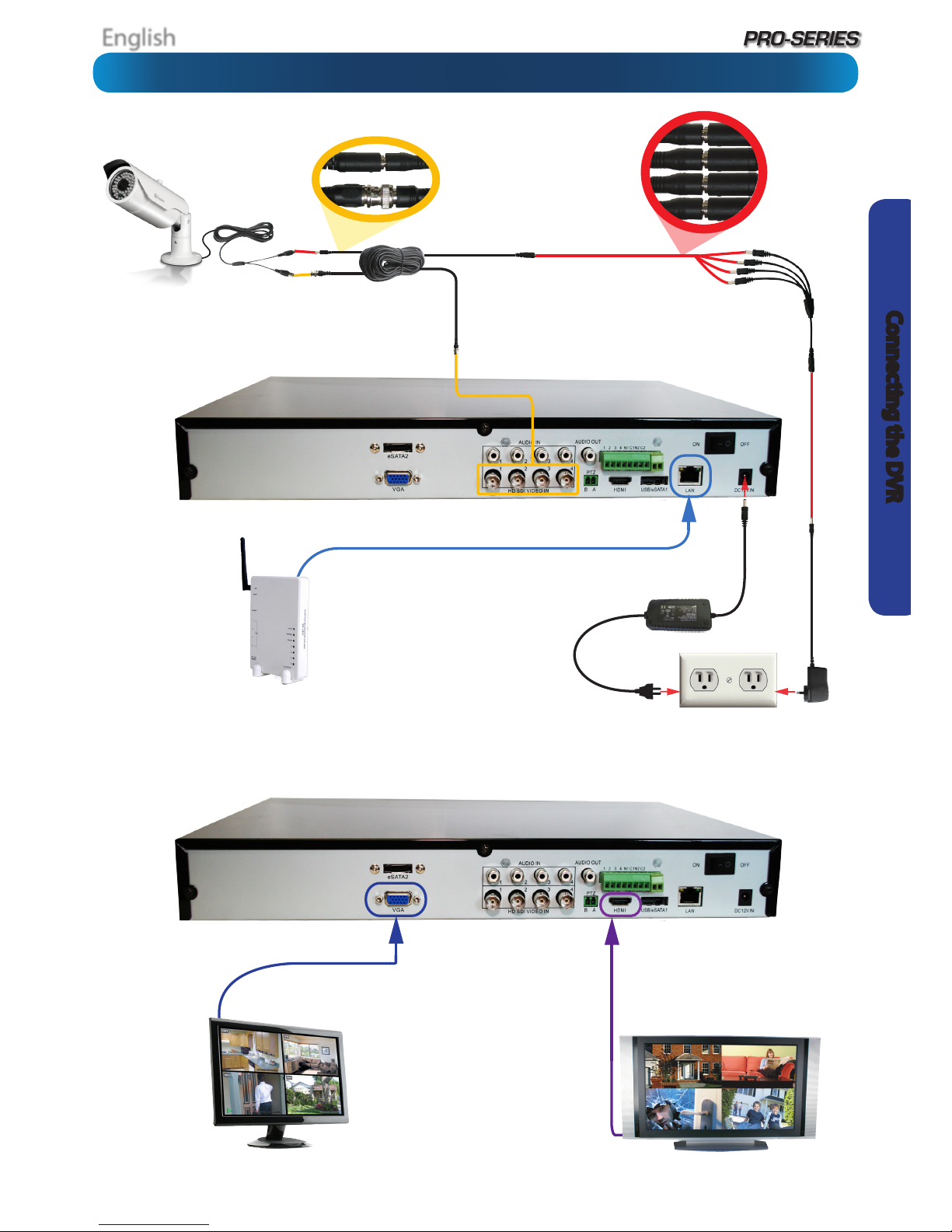
Connect the DC12V
Output from the
power supply to
the power input.
Connect the SDI outputs from
your cameras into the marked SDI
inputs on the rear of the DVR.
Connect your cameras to
power, using the a powersplitter (if included).
Connect the power
adapter(s) to a wall outlet.
If you’ve got a
monitor with
VGA but not
HDMI, connect
it to the VGA
output on the
DVR.
If you’ve got a TV or monitor with
HDMI in, connect to the HDMI port
on the DVR.
Connect an ethernet
cable from the LAN
port on the DVR to
a spare port on your
router.
Connection Diagram

English
8
Connecting the DVR
The Audio Out
port can be used
to connect a
stereo, speakers,
headphones or
other external sound
device.
The Audio In ports can be
used to connect audio devices
to the DVR. Obviously, your
microphone probably won’t look
like that one - they’re often built
into cameras.
The PTZ port (RS485)
can be used to connect
compatible PTZ
devices, such as this
Swann PTZ SDI dome.
Connecting Additional Devices
Connect the mouse to the front USB 2.0 Port.
This port can also be used to connect USB devices to
backup to, but you’ll need to unplug the mouse to do it.
An external
hard drive with
an eSATA port can
be connected to the
eSATA port on the DVR,
and can be utilized in the
same manner as the internal
HDD.
The combination USB/eSATA1 Port is used
for backing up footage. You can connect:
- A USB Flash Drive
- A USB Hard Drive
- An eSATA Hard Drive
Note: If using USB storage media, USB 2.0 (or
faster) devices are recommended.
English
9
Connecting the DVR
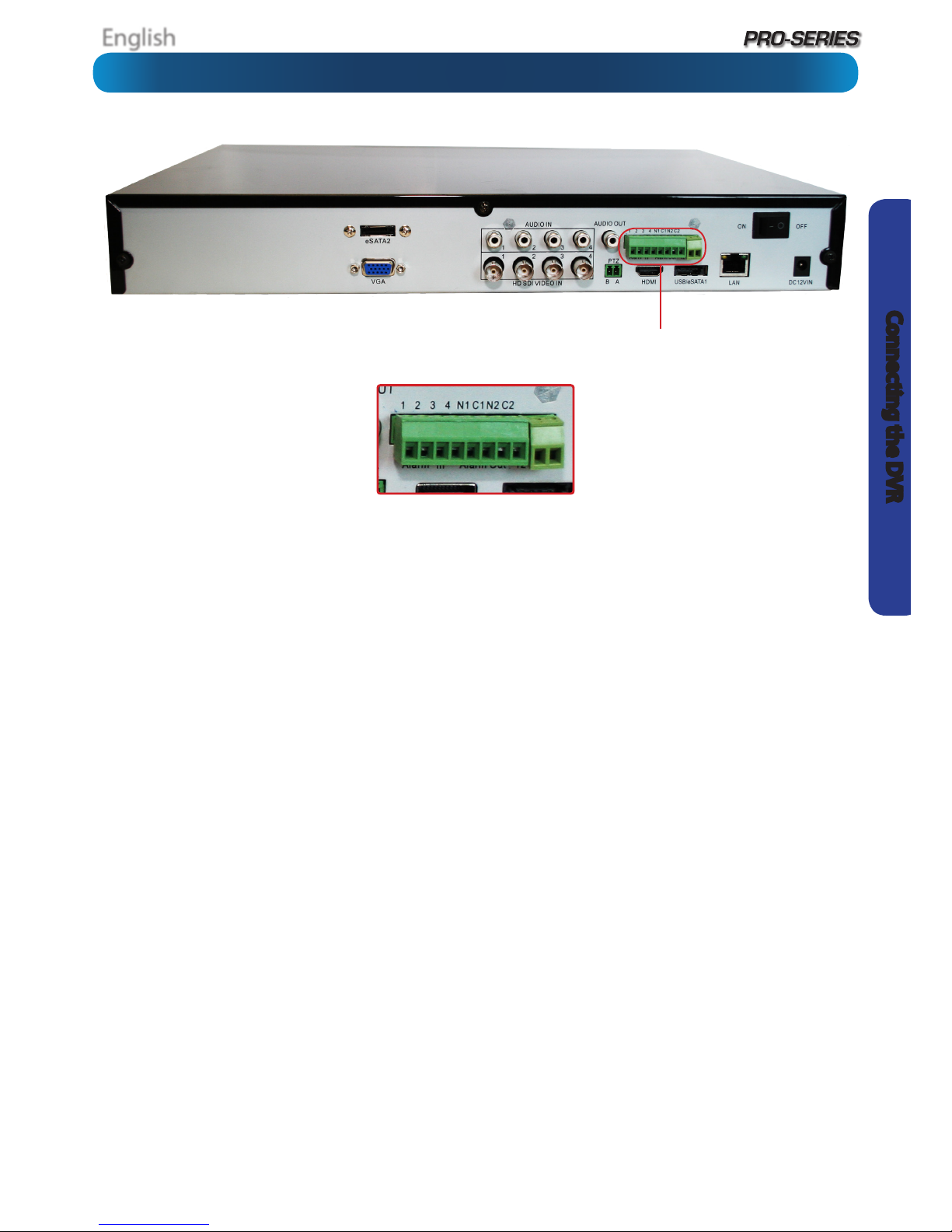
The Alarm Ports on the DVR sport a removable terminal block.
The terminal block is used to facilitate easy connection and
disconnection of so many wires, rather than having to unscrew
each one individually if you want to move the DVR or access
the rear panel.
Alarm In 1 - 4: Connect the output from external sensors
here. Only one of the two outputs should be connected here,
the other should be connected to a 12V terminal and/or the
Ground terminal, depending on the requirements of the
sensor (consult the documentation for the sensor).
The Alarm In number does not directly correspond with a
channel number - these can be set later (see “Alarm: Sensor”
on page 46 in Advanced Conguration for details).
12V: Active DC power output. Connect any sensor device
inputs which require 12V DC here. The Alarm IN connections
share common +12V DC connections.
GND: The ground connections. The Alarm IN and Alarm OUT
connections share a common ground.
Alarm Out: The outputs for connecting an external alarm
device, such as a siren or security lights, to the DVR.
N1, C1: The outputs for Alarm Out 1. Check your alarm device’s
documentation to see which ports should be connected.
The Alarm I/O Block
The Alarm & Sensor I/O Block

English
10
Basic Setup
SDI: How it compares to traditional CCTV
Basic DVR Operation
Swann DVRs can feature two dierent kinds of input channels,
the high denition SDI channels, and the standard denition
composite video channels. This DVR is entirely SDI, so only
supports SDI cameras. For best results we recommend using
Swann 1080P SDI cameras.
SDI
SDI technology allows 1080p Full HD images to be transmitted
via similar cables to traditional, analogue video. By encoding
the information digitally, you can transmit up to six times the
resolution of traditional CCTV cameras
This means that:
• Your images will be far more detailed than traditional
CCTV camera footage.
• You can use wider angle cameras to cover more area at
the same level of detail as traditional cameras
• Your DVR is going to require more hard drive space to
record images from your cameras than traditional CCTV
cameras (all that quality has to be stored somewhere!)
To maximize the (many) advantages of SDI while minimizing
(few) drawbacks:
• As much as possible, make use of Motion Detection and/
or Alarm-based recording as your primary recording
mode(s). This will help save hard drive space as the DVR
will not be lling it’s internal storage with images of
nothing happening.
• It’s more important that cameras with adjustable lenses
(such as adjustable zoom or focus, or both) must have
these set as accurately as possible.
The USB Mouse (Recommended)
The easiest way to operate the DVR is to use the included USB
optical mouse - we put together the look and feel of the menu
system specically for mouse-friendly navigation.
The controls are pretty easy to remember - heck, there are only
two buttons. It couldn’t be simpler.
Left click:
• Selects an item or conrms a choice.
Right click:
• Opens the menu bar from the live viewing screen.
• Returns one “step” from a submenu.
• Opens a context menu in some settings screens.
The Scroll Wheel:
• Can be used to adjust the values of sliders and scales
when highlighted by the mouse.
Of course, you don’t have to use the mouse.
The Front Panel
The buttons on the front panel are adequate for operating the
DVR, but they’re hardly ideal for ongoing use.
Between Menu, Select and the D-pad (directional pad) you can
navigate through all the DVR’s menus and congure almost
any setting. It’s a little clunkier than the mouse and it’s not as
quick and easy, but it does save a little space.
Wireless Mice
Many wireless mice are compatible with the DVR. The only
kinds of wireless devices compatible are those that interface
in the same manner as regular wired devices: typically, these
will be mice which come with a dedicated USB receiver which
is pre-paired to the mouse.
Combination wireless receivers (such as those that come with
keyboard/mouse combinations) are usually NOT compatible
with the DVR. We suggest avoiding them.
Note that Bluetooth devices are NOT compatible with the
DVR. Use a wireless mouse that has a dedicated USB receiver.
English
11
Basic Setup
Basic Setup: General
The Setup Wizard will run automatically the rst time you start the DVR.
The wizard will guide you through all the settings you need to get your DVR up and working, specically:
• Choosing your Language
• Setting Video Input and Output Formats and Resolution
• Setting the Date, Time and your Time Zone
• Initializing and/or Formatting your Hard Drive
• Conguring the DVR to operate on your Network
• Setting up a Dynamic DNS for remote access
• Synchronizing the DVR’s time with an online server
• Choosing the settings for Daylight Savings Time (DST)
• Creating Username(s) and Password(s)
Note: There are still a few things you’ll really want to setup after you’ve nished with the wizard - the theory is that, once you’ve got
through the set up wizard, you can install the MyDVR software on a PC connected to the same network and congure the remaining
options via your computer.
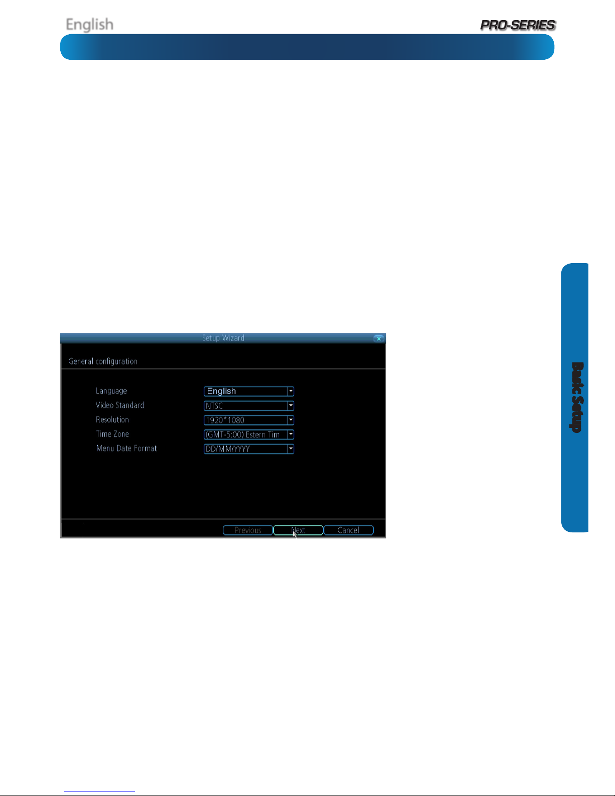
General Conguration
Language: Choose the language you’d
like the menu system to be displayed in.
Video Standard: Choose between NTSC
(for the USA, Canada, Mexico, Japan,
Korea and some other regions) or PAL
(UK, Europe, Australia and some other
areas). If this is set incorrectly, images
captured under certain conditions (such
as under uorescent lights or near a
television) will appear to icker.
Resolution: How many pixels the DVR
will output. Typically, you’ll want to set
this to be equal to the native resolution
of your monitor/television (check the
manufacturer’s documentation). If
your monitor’s native resolution isn’t
an option, then you’ll want to use the
highest resolution possible without
exceeding the maximum resolution of
your monitor.
Time Zone: Choose the time zone you’re in. It’s really important to select the right time zone if you’re using NTP (Network Time
Protocol).
Some common time zones: In the USA, EST (Eastern Standard Time) is GMT -5:00, where PST (Pacic Standard Time) is GMT -8:00.
The UK is GMT +0:00, and the East Coast of Australia is GMT +10:00.
Menu Date Format: How you’d like the date to be displayed. Choose whichever format is standard in your region.
If you need to change any of these settings later, you can nd these options:
Main Menu -> System -> General
English
12
Basic Setup
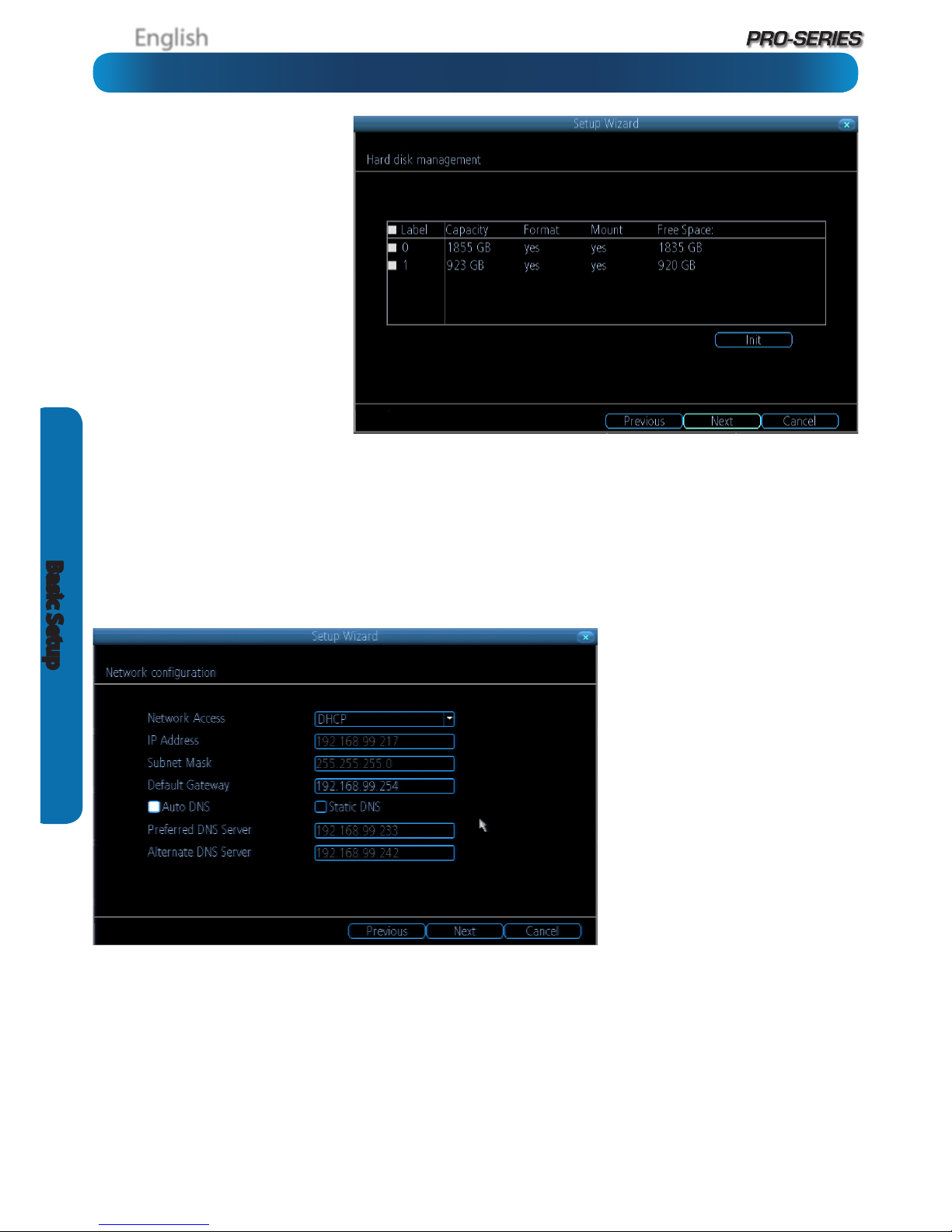
HDD
Init.: Initializes the hard drive. You’ll
only need to do this for drives once,
assuming that it’s not already initialized.
If the Mount column reads “No” then
choose Init. to initialize the drive.
Label: A quick way of dierentiating
between hard drives. For the rst setup,
there will usually only be one hard
drive - you can always add and initialize
another hard drive later (either internal
or connected via eSATA).
Capacity: The total amount of space
on the hard drive. This will typically be
slightly less than the rated capacity of
the hard drive as a fraction of the space
is required by the le allocation table
(FAT).
Format: Whether the hard drive has been formatted to operate with the DVR. When the hard drive is formatted appropriately,
this will simply read “yes”. If it says anything else, such as an ominous “no”, then select the disk and choose Format.
Mount: Whether the drive has been initialized and is detected by the DVR. If the drive isn’t mounted then it needs to be
initialized (see above).
Free Space: The amount of available space on the hard drive.
Network Access
We’re not going to pretend this isn’t the
most complex aspect of conguring the
DVR, but if your router supports DHCP
and UPnP, then there’s nothing to do
here.
Recommended:
Don’t change anything.
Ensure that the Network Access is set to
DHCP and that UPnP is enabled on your
router - it should just work.
If your router doesn’t support DHCP:
Then you’ll need to manually assign the
address of the DVR. If you’ve already
setup your network, we assume you
know what you’re doing. See “Addendum:
Third Party Hardware” on page 57 for
more information.
If your router supports DHCP but not UPnP: For local access (i.e. a PC connected to the same network) just set the Network
Access to DHCP. For remote access (i.e. a device connected via the Internet), you’ll need to manually forward ports on your router.
See “Addendum: Third Party Hardware” on page 57 for more information.
If you don’t know how to manually address devices and don’t have access to someone who does, you may want to consider
upgrading your router - we think that DHCP and UPnP are neat features that are well worth having.
There’s heaps more information on IP Addresses, DHCP, UPnP and all manner of remote access information later in this booklet.
In addition to “Addendum: Third Party Hardware” on page 57, have a look at “Network: General” on page 37 and have a word
with whoever set up your network - they might be able to help you.
Basic Setup: HDD & Networking
English
13
Basic Setup
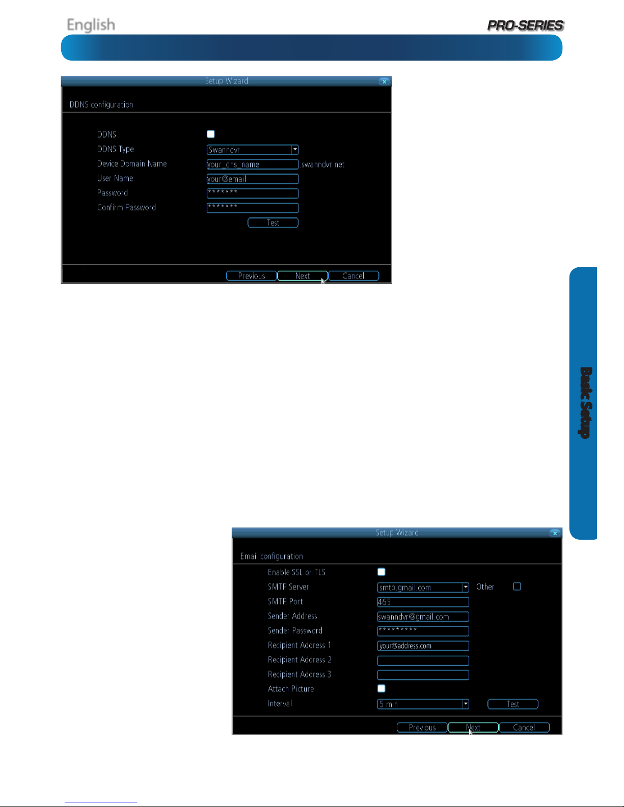
DDNS
A Dynamic DNS is a service which will let
you assign an address to your DVR so you
can access it via the Internet.
There’s more information about DDNS,
how to congure it and what it means
for you when remotely accessing the
DVR later in this manual. Have a look at
“Network: Advanced: DDNS” on page 39
for more.
DDNS Type: The DDNS server you’re
using. We recommend SwannDVR - you
can sign up for your free account at www.
swanndvr.net.
Device Domain Name: The domain name
you chose when signing up for your DDNS
account.
User Name: The username you selected when you signed up for your DDNS account. If you’re using SwannDVR and followed
the suggested username guidelines, this will be your email address.
Password: Enter the password you used when you signed up for your DDNS account.
Conrm Password: Re-enter the password to conrm.
Test: To check if the DDNS is working, click the Test button. After a short delay, a message will be displayed on-screen, informing
you whether the update was successful or not.
If the test is unsuccessful, a message will appear onscreen informing you that the “Update was Unsuccessful”. This could mean
there’s a problem with your network setup, or there’s a problem with the DDNS Account Name and Password you’re using.
Before DDNS will work, you’ll need to register an account with the DDNS provider of your choice. We recommend SwannDVR, as this
is a free service which we support directly. Boot up your computer and sign up at www.swanndvr.com.
Email
If you want the DVR to send email alerts as alarm events are detected, then you’ll need to congure an outgoing email server for
the DVR to use, and choose an email address for it to send to.
We recommend creating an account with Gmail (www.gmail.com) specically for the DVR. These instructions assume you’re
using a GMail account. If you’re using a dierent email, see “Network: Advanced: Email Settings” on page 41 for details.
Enable SSL or TLS: Enable.
SMTP Server: Choose smtp.gmail.com
SMTP Port: 465 (this value will self-populate)
Sender Address: your_email@gmail.com
Sender Password: The password you
chose for the GMail account.
Recepient Address 1, 2, 3: Choose up
to three email addresses for the DVR to
send mail to.
Attach Picture: When selected, the DVR
will attach a still image to better illustrate
what has caused the alarm/alert state.
Interval: The minimum amount of time
that must elapse after the DVR sends
an email alert before it can be triggered
again.
Other: Allows for custom denintion of an outgoing email server. See “Network: Advanced: Email Settings” on page 41if you want
to use an email server other than Gmail. For advanced users ONLY.
Basic Setup: DDNS & Email
English
14
Basic Setup
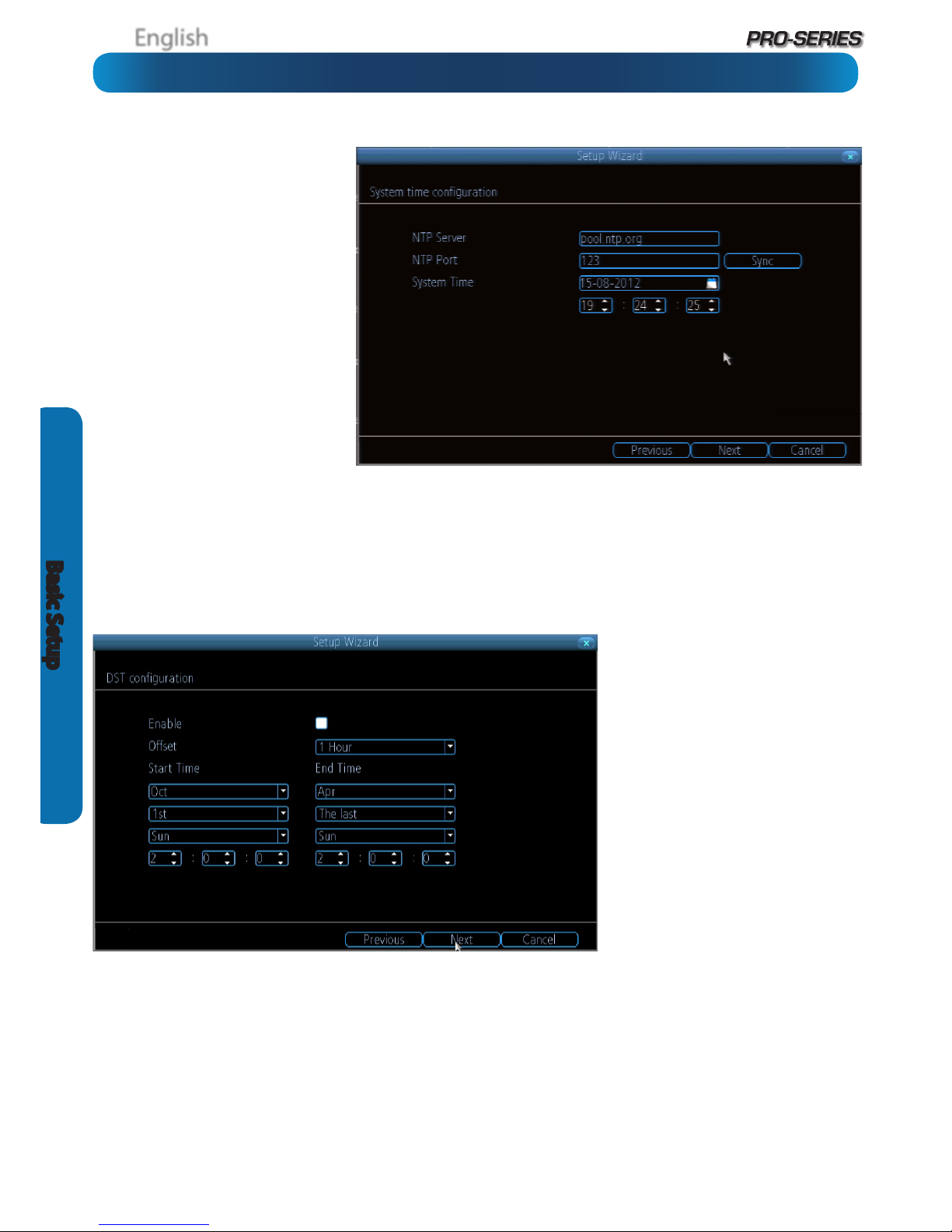
NTP
NTP stands for “Network Time Protocol”.
It’s a way for the DVR to automatically
update its internal clock and ensure it’s
always in sync. There’s no requirement
to use NTP, but it’s easy to setup and
free to use, so there’s really no reason
not to.
NTP Server: The server you’d like to use
for NTP. They’re all quite comparable
in terms of reliability and accuracy, so
unless you’ve got some kind of master
plan for world domination (which is
aected by the time, for some reason)
then the default (pool.ntp.org) works
ne.
NTP Port: The default is 123. You
should only change this if you’re using
a dierent NTP server, and you know
they use a dierent port. If you’re using
pool.ntp.org, ensure the port is 123.
Sync: Triggers the DVR to automatically synchronize its internal clock with the time server immediately. If your DVR is connected
to the Internet and the network is correctly congured, this will update almost instantly.
System Time: The DVR’s current clock reading.
DST Conguration
You can congure the DVR to
automatically update it’s internal clock
when daylight saving starts and ends.
Note that using DST and NTP
simultaneously can cause problems,
depending on your NTP server and how
DST works in your locale.
Enable: Whether the DVR will
automatically adjust the time for DST or
not.
Oset: The amount by which the time
changes during DST. For the vast majority
of locations, the oset is one hour, but
exceptions to this rule exist.
Start Time / End Time: When DST begins
and ends in your locale.
Basic Setup: NTP & DST

English
15
Basic Setup
Account Conguration
User Name: The name you’d like to
use for the account. An account can
be called anything you like (up to 16
characters in length) except the default
Admin account, which is always called
“Admin”. We suggest using this as the
default all-access account for the DVR.
Password: The password you’d like
to be associated with the selected
account. A password can be between
1 and 8 characters in length, and
consists of numbers only (no letters or
symbols).
Conrm Password: Re-enter the
password to ensure accuracy.
Level: The level of access that the selected account will have. There are three levels of access: Guest, User or Admin.
Guests: Can view live images from the cameras, but cannot access recorded footage, nor can they alter any settings.
User: The most customizable level of access to the DVR. You’ll be able to set a User account to have as little access as a Guest
account, or nearly as much power as an Admin account. User accounts will probably make up the majority of accounts registered
to a DVR if there are multiple users requiring varying levels of access.
Finishing the Setup Wizard
When you choose Finish, the DVR will update and save your settings. It may reboot while doing so.
If you don’t want the Setup Wizard to be dispalyed upon startup in the future, uncheck the “Run Wizard at Startup” checkbox.
Display wizard when booting up (checkbox): While this is highlighted, the DVR will automatically run the conguration
wizard when booted up. Simply click this box to de-select it, and the wizard won’t run automatically in future. You can run the
wizard at any time by clicking the icon on the DVR menu tray.
Basic Setup: Account Conguration & Completion
English
16
Basic Setup
Your DVR comes with powerful remote access and interface
software, called MyDVR. You can setup and congure almost
all aspects of the DVR from the MyDVR interface.
The MyDVR software will allow you to:
• view images from your DVR in real-time,
• playback recorded footage,
• copy footage to your local PC and
• adjust settings and congure the DVR.
In fact, the MyDVR software is so powerful, you don’t even
need to connect a monitor to the DVR if there’s a computer on
the local network that you’re running MyDVR on.
For quick and easy conguration of the DVR’s settings,
recording quality and schedule, we suggest using the
remote interface in MyDVR.
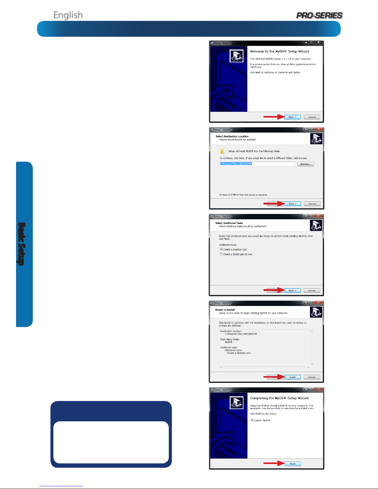
How to install MyDVR:
• Insert the included CD into your computer.
• Locate the le called MyDVR Windows vxxxx.exe (the x
represents numbers showing the version) and run this le.
You may be asked by UAC (User Account Control) to allow
MyDVR to “make changes” to your system. Select Allow or
Continue.
• You’ll see an installation wizard. Simply follow the prompts
to install the software.
• Once the MyDVR software has been installed, it should
automatically detect your DVR on your network.
Minimum PC Requirements:
2.0GHz or faster CPU (Dual-core recommended)
1GB or more RAM (2GB recommended)
10/100Mbps Network (1000Mbps recommended)
Internet connection (512kbps+ recommended)
1024x768 resolution (1280x720 recommended)
Supported Operating Systems
Microsoft Windows XP, Microsoft Windows Vista, Microsoft
Windows 7
NOTE: Windows XP, Windows Vista and Windows 7
are registered trademarks of Microsoft Corporation.
Basic Setup: Installing MyDVR on PC
Got a Mac?
Check out
www.swann.com/mydvrmac
for the latest Mac-based remote
access software.

English
17
Basic Setup
Before running MyDVR for the rst time:
Ensure your DVR is connected to a network and (if accessing
via the Internet) you know the Public IP Address of the DVR
or the DDNS address (see “Network: Advanced: DDNS” on
“Network: Advanced: DDNS” on page 39 for more).
That your network is set to DHCP addressing or the DVR
has been congured to use STATIC addressing (see “Network:
General” on page 37).
That UPnP is enabled on your router (see your router’s
documentation to learn more).
If you’re accessing the DVR via a LAN (local network):
• Select LAN under the heading Network Type (unless your
computer has performance issues - then select WAN. See the
note on multiple monitors, below/right).
• Your DVR should automatically appear in the list of
compatible devices near the top of the window.
• If your DVR does not appear, choose Scan Device in LAN.
If this doesn’t work, then it indicates some kind of local
network fault.
• Select your DVR from the list - it will probably be the only
thing there, unless you’ve got another Swann DVR.
If you’re accessing the DVR via the Internet:
• Select WAN under the heading Network Type.
• If you’re using a Fixed Public IP address, choose IP
Address under Register Mode, and enter the IP address
into the space marked IP.
• If you’re using a DDNS hostname, choose Domain Name
under Register Mode, and enter the DDNS domain name
into the eld labeled Domain.
• If you’re using the SwannDVR DDNS service, your address
will be: yourDDNSname.swanndvr.net
• Enter the Server Port for the DVR. The default is 9000.
The DVR won’t be able to automatically detect this over the
Internet - you’ll need to remember it if you’ve changed it!
• Enter your Username and Password.
• Choose Login.
Note: Multiple Monitors
The MyDVR software does not support hardware acceleration
when using multiple monitors. On some systems, this can cause
signicantly reduced performance.
If you experience slow playback or the video is not being displayed
at all, disable all monitors but your primary one. Selecting WAN
mode (even over a local network) can also improve performance.
If you’re logging in to the DVR for the
rst time via a local network, then use
the following settings:
• IP: This eld will self-populate when
you select a DVR from the list.
• Server Port: The default is 9000.
MyDVR will automatically detect the
server port of the DVR.
• Username: To get full control of the
DVR, use the default administrator
username: admin. You can create
other accounts, but the default is
always called admin.
• Password: Enter the admin account
password here. If you haven’t set a
password yet, then leave this eld
blank (and we suggest that you set a
password as soon as possible).
MyDVR: Logging In
Default Password Information
To ensure your privacy, this DVR supports password protection.
The default, all-access username is “admin”. If the DVR asks you to log in before you’ve set a password, enter
admin as your username and leave the password blank. This will give you access to all areas of the DVR.
The password function is disabled by default. However, if you’re asked for a password, the default is “12345”.
To ensure your ongoing privacy, we strongly recommend setting a password as soon as possible. Choose
something that you’ll remember, but that others would be unlikely to guess.
If you do manage to lock yourself out of the DVR, you’ll need to contact us at the Swann Technical Support
Telephone Helpdesk - the number is on the back cover.
English
18
Basic Setup
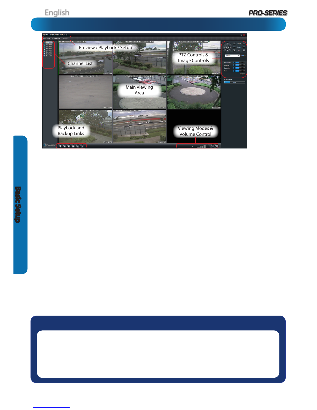
MyDVR: Interface
Preview: The default splash live-view screen of MyDVR.
The screen layout emulates the multi-channel live view
screen of the DVR, showing you images coming directly from
your cameras in near real-time (some delay is caused by the
network/Internet connection you’re using to access the DVR).
You can select a single camera, or multi-channel viewing by
using the Viewing Mode buttons in the lower right corner.
Playback: Opens the Playback interface, which operates in
much the same way as the playback interface on the DVR itself.
Setup (Conguration): Allows access to both the Local
Cong screen and Remote Conguration menus.
Local Cong: Denes how MyDVR will manage and save
footage and still images to your local PC.
Remote Cong: Allows access to the DVR’s settings. The
congurable options are very similar to those you’ll nd in the
DVR menus.
Main Viewing Area: Where images from your camera will
be shown. Select Preview to return to this view from the
Playback interface or the Cong menus.
Playback / Backup Links: Quick access to playback and
backup.
PTZ Controls: For controlling PTZ devices. They operate in the
same way as those you’ll nd on the DVR itself.
Image Controls: You can alter the brightness, contrast,
saturation and hue of your images here. They operate in the
same way as those in the DVR’s menu (see “Display: Camera”
on page 28 for more information).
Viewing Modes: Choose between single camera viewing or
four channels at once (2 x 2)
Volume Control: Alters how loud the audio output from the
DVR will be. Remember that the nal output volume will also
be aected by the master volume control of your operating
system, as well as the levels set on speakers or ampliers
connected to your system.
CPU Loading: How hard your computer is working to decode
and display images as they arrive from the DVR. If this is
consistently high, you can try:
• disabling multiple monitor setups. The MyDVR application
doesn’t support hardware acceleration across multiple
monitors. Disabling all but your primary monitor will
greatly increase performance.
• reducing the quality of the video. Select WAN from the
login screen instead of LAN.
• reduce the number of video feeds being displayed. Select
a channel and click Stop to disable the monitoring.
• switch to single channel view.
Main Viewing
Area
Playback and
Backup Links
Viewing Modes &
Volume Control
PTZ Controls &
Image Controls
Preview / Playback / Setup
Channel List
Need more details?
The overview of the DVR settings presented over the next few pages is just that - an overview.
The full explanation of the DVR’s menu system and conguration options are listed in detail from
page 25 onwards. The DVR’s menu system is functionally very similar to the MyDVR software
interface, and you’ll nd more detailed information about all menu options and settings there.
The relevant page for additional information is listed next to each menu screen.
The default
MyDVR live view
interface showing
an 8 channel
screen. The 4
channel screen
is functionally
identical, with
the same control
layout but opens
Quad view (2 x
2) rather than
All view (3 x 3) as
default.
 Loading...