

Page 1
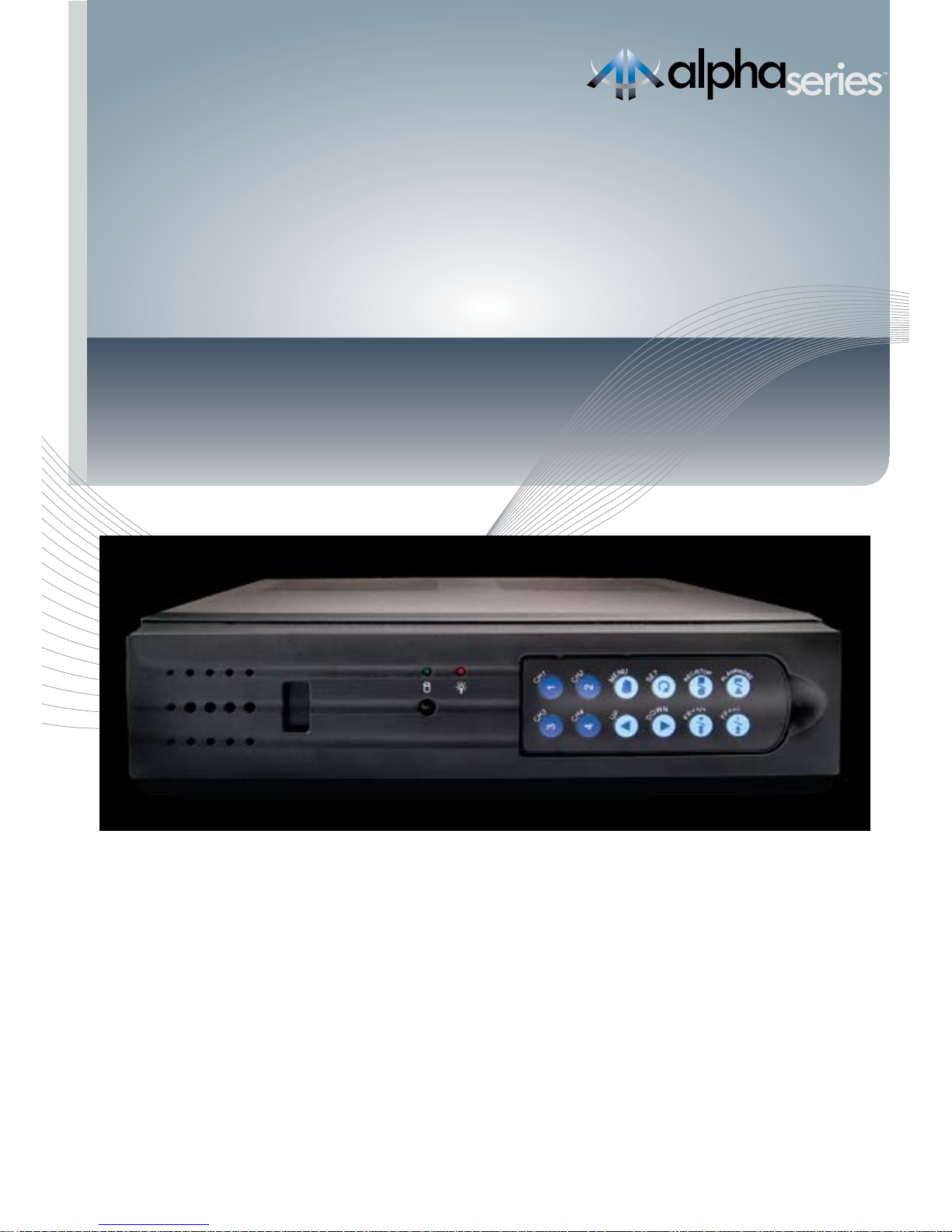
Alpha D01 DVR
4 Channel Digital Video Recorder
SWA41-D1
www.swannsecurity.com
Operating Instructions
Page 2

22
FCC Verification:
NOTE: This equipment has been tested and found to comply with the limits for
Class B digital device, pursuant to part 15 of the FCC Rules. These limits are designed to provide reasonable protection against harmful interference in a residential installation. This equipment generates, uses and can radiate radio frequency
energy and, if not installed and used in accordance with the instructions, may
cause harmful interference to radio or television reception, which can be determined by turning the equipment off and on, the user is encouraged to try to
correct the interference by one or more of the following measures:
· Reorient or relocate the receiving antenna
· Increase the separation between the equipment and the receiver
· Connect the equipment into an outlet on a circuit different from that to which
the receiver is connected
· Consult the dealer or an experienced radio/TV technician for help
These devices comply with part 15 of the FCC Rules. Operation is subject to the
following two conditions:
(1) These devices may not cause harmful interference, and
(2) These devices must accept any interference received, including interference
that may cause undesired operation.
IMPORTANT NOTE: Prohibition against eavesdropping
Except for the operations of law enforcement officers conducted under lawful
authority, no person shall use, either directly or indirectly, a device operated pursuant to the provisions of this Part for the purpose of overhearing or recording the
private conversations of others unless such use is authorized by all of the parties
engaging in the conversation.
WARNING: Modifications not approved by the party responsible for compliance
could void user’s authority to operate the equipment.
IMPORTANT SAFETY INSTRUCTIONS:
· Make sure product is fixed correctly and stable if fastened in place
· Do not operate if wires and terminals are exposed
· Do not cover vents on the side or back of the DVR and allow adequate space for
ventilation
Before You Begin
Page 3

3
Contents
Before You Begin 2
Contents 3
Package Contents 4
DVR Layout 5-6
Front Panel & Removable Remote 6
Rear Panel 6
Connections & Installation
Connecting Cameras and Power Adapter 7
Connecting the DVR to a TV Monitor 8
Turning the DVR On/Off and Auto Recovery 8
Menu Operation 9
Accessing and Navigating the Menu System 9
Setting DVR Time 9
Image Display 10
Single Camera View 10
Multi Camera View 10
Camera Menu 11
Record Menu 11-12
Motion Detection Menu 12-13
Screen Menu 13
Audio Menu 14
System Menu 14-15
Time Search 15
Language Menu 16
Exit Menu 16
Starting the DVR With a New Hard Drive 16
Changing the Hard Drive 17
Backing Up Footage to PC 18
Viewing Backup Footage on a PC 19
Using the VVFPlayer software 19
VVFPlayer Interface 19
Extract footage from a larger video clip 20
Exporting an AVI file 20
Troubleshooting Guide 21
Technical Specifications 22
Warranty Information 23
Technical Support Details Back cover
Page 4

44
Package Contents
Alpha D01 DVR Unit
Front Panel Remote Control X 2
Operating Instructions
Easy Setup Guide
Power Adapter with Cable
Software CD
RCA Video Cable
BNC to RCA adapters X 4
Security Stickers (4 Pack)
If you are missing any of the components above, contact Swann
Communications for assistance.
Page 5
5
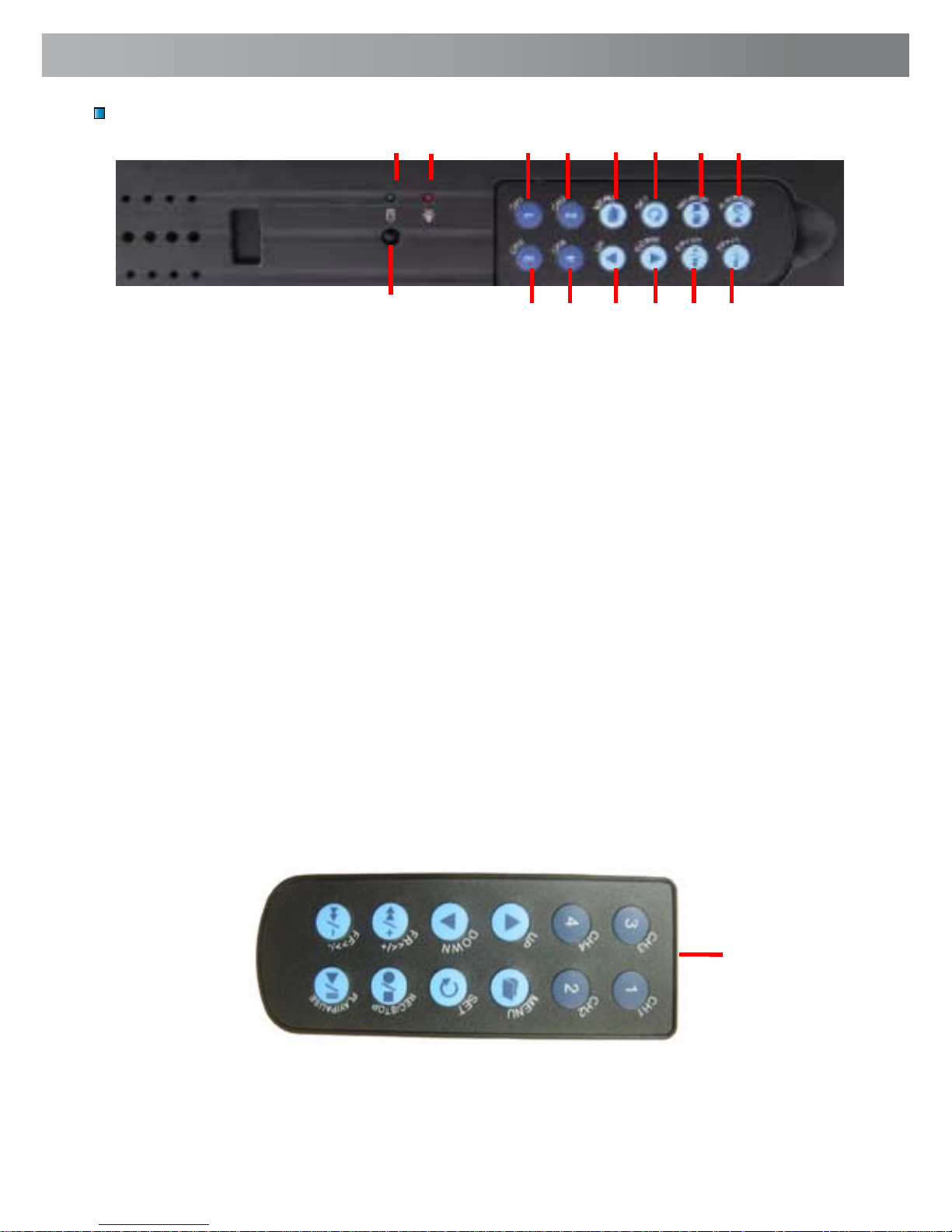
1. Hard Drive Indicator
Lights when hard drive is active (flashes when recording,
searching etc.)
2. Power Indicator
Lights on when DVR powered
3. Channel 1 Button
Press to view camera 1 in full
screen / Press again to return to
quad view
4. Channel 2 Button
Press to view camera 2 in full
screen / Press again to return to
quad view
5. Menu Button
Press to select Menu / previous
menu / exit menu
Note: some menu functions
require a password. Default
password is “111111”
6. Set Button
Press to confirm selection
7. Record/Stop Button
Push to begin or stop recording
Note: will not work if time
or motion record is set.
8. Play/Pause Button
Push to open EVENT LIST,
begin last recording or pause
playback
9. Remote Control Sensor
10. Channel 3 Button
Press to view camera 3 in full
screen / Press again to return to
quad view
11. Channel 4 Button
Press to view camera 4 in full
screen / Press again to return to
quad view
12. Up Arrow
Move cursor up in menus
13. Down Arrow
Move cursor down in menus
14. Rewind Button
Push to rewind playback /
Move cursor left in menus
15. Fast Forward Button
Push to fast forward playback
/ Move cursor right in menus /
Activate AUTO SWITCH function
Note: 3-15 removable front
panel remote
DVR Layout
Front Panel & Removable Remote
1
10 11 12 13
2
3 4 5 6 7 8
9
14 15
The remote control contains a battery that must be activated before use.
Find and remove the clear plastic tab at the bottom of the remote. The
remote will now be ready for use.
Using the Remote Control for the First Time
IR LED
Remove
plastic tab on
this end of
remote.
Page 6
66
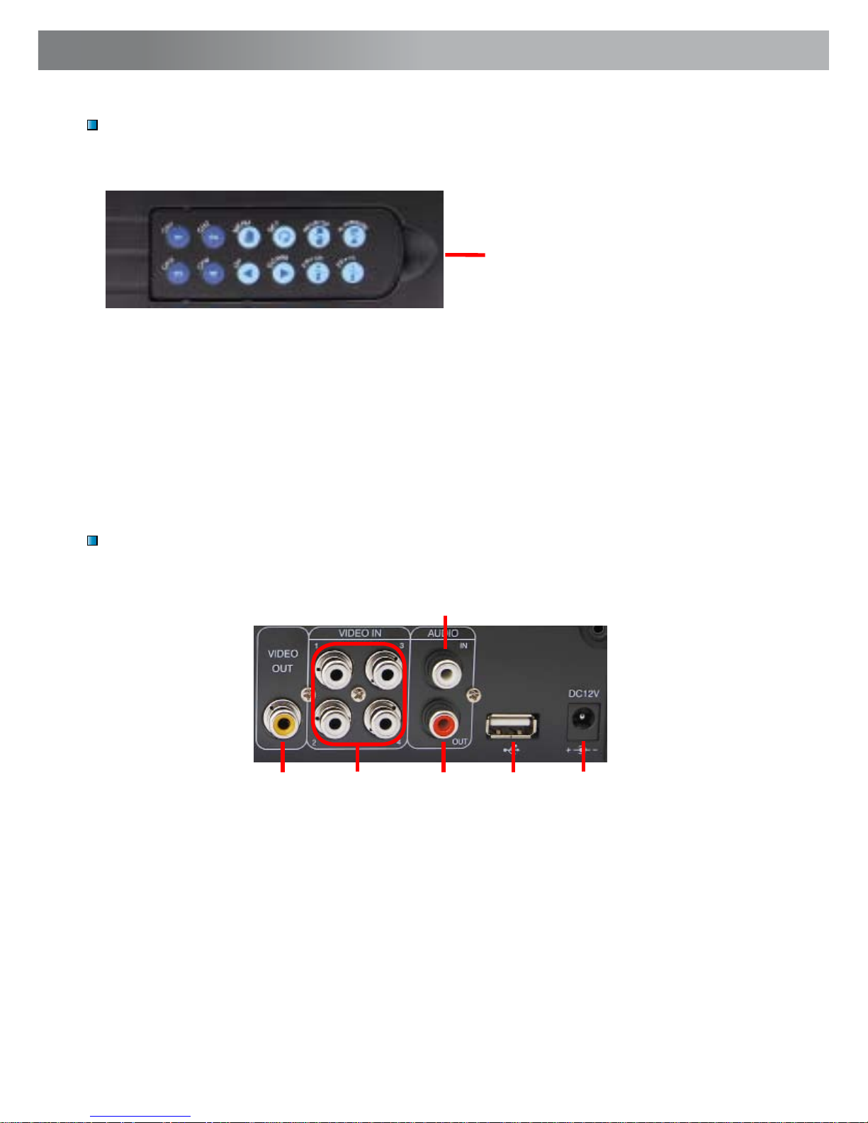
1. Video Output
Output to TV
2. Video Input
Inputs for cameras x 4 RCA
3. Audio Input
Input for microphone 1 x RCA
4. Audio Output
Output to speaker 1 x RCA
5. USB Connection
Download backup footage to Flash Drive (not
included)
6. DC 12V Power Input
Power Adapter connection for DC 12V adapter
only
Rear Panel
3
4 51 2
6
DVR Layout (cont)
Use the indent to
remove the control from
the DVR unit
Removing the Remote Control
Note: To secure the DVR and prevent unauthorised use remove the
remote and store in a secure place.
Page 7
7
Connecting Cameras and Power Adapter
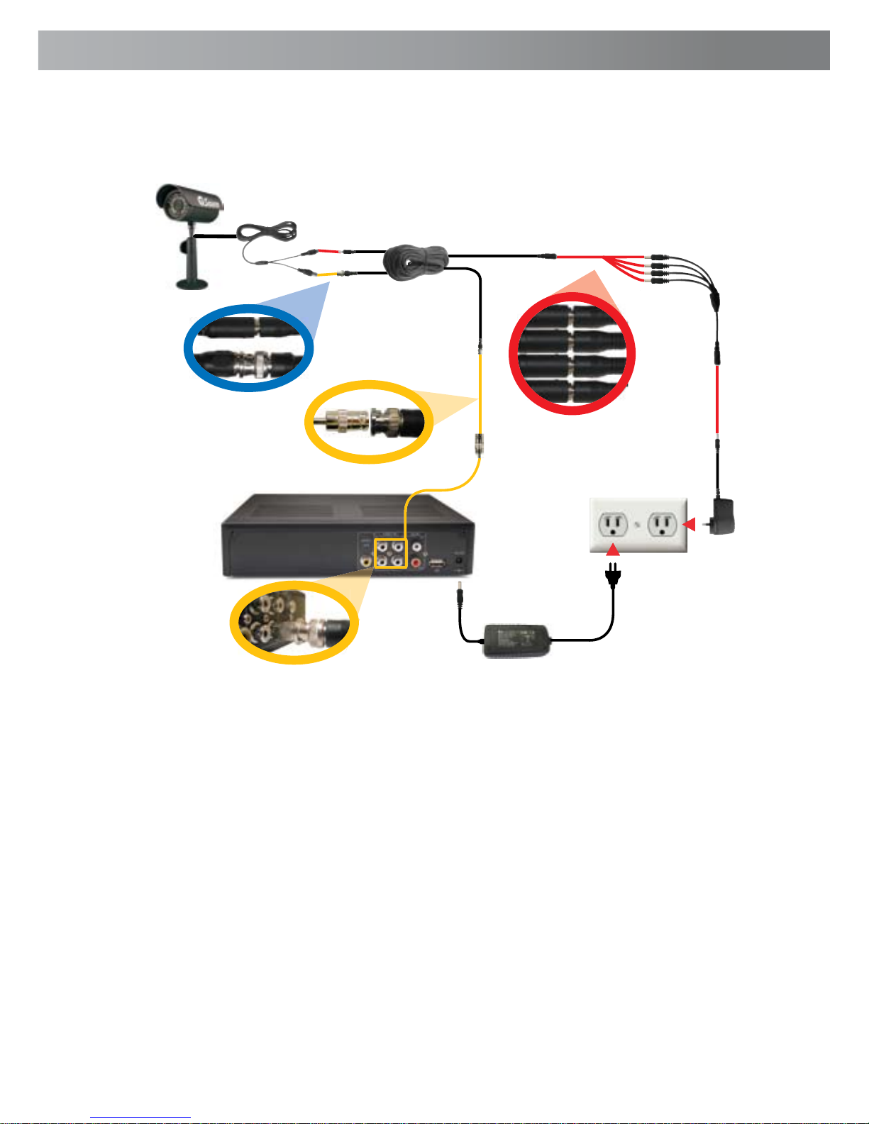
1. Connect the Power and BNC ends of the Security Camera to an
Extension Cable.
2. Connect the BNC end of the Extension Cable to the RCA adapter.
3. Connect the end of the RCA adapter to camera input on the back of the DVR.
4. Connect the power end of the Extension Cable to the Power Splitters.
5. Connect the Power Splitter to the Camera Power Adapter.
6. Plug in the Camera Power Adapter and the DVR Power Adapter to mains
power outlets.
1
2
3
4
5
Cameras and
accessories optional
6
Page 8
88
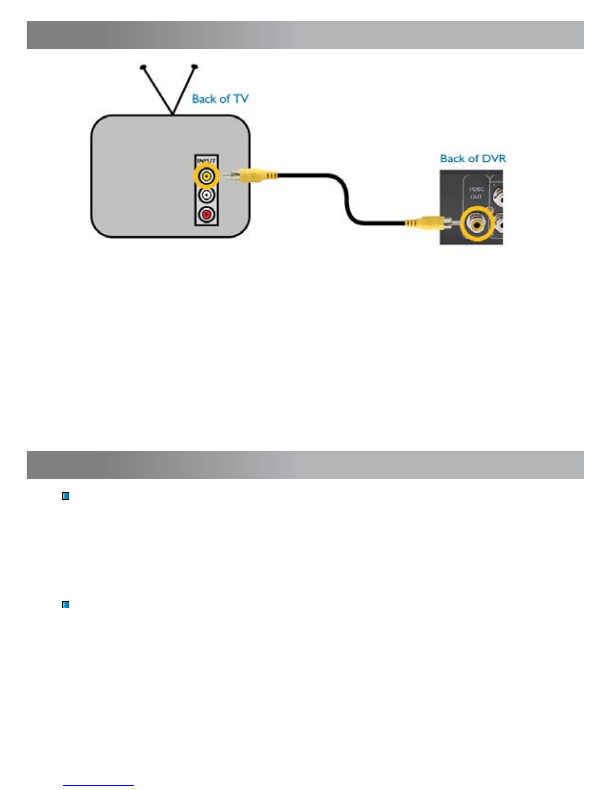
Connecting the DVR to a TV Monitor
1
2
1. Connect an RCA end of the Video Cable to the Yellow Video
INPUT on the back of the TV Monitor.
2. Connect the other RCA end of the Video Cable to the Video OUTPUT
connection on the back of the DVR.
3. Tune your TV to the correct input channel to view the DVR. Using your TV’s
Remote Control press the Input button until the DVR appears on screen. Most
TVs will label this button as Input, Video, Source, A/V, TV/AV, Line, Channel 0,
etc. If you are unable to view your DVR on your TV contact your TV’s manufacturer for assistance.
Back of TV
Powering the DVR On/Off
To turn on your DVR connect the Power Adapter to the DC 12V input on the
back of the unit. To turn the DVR off unplug the DVR from the wall outlet or
power point.
If the DVR will not be in use for extended periods of time Swann recommends
unplugging the unit.
Auto-Recovery Feature
The Alpha D01 DVR is equipped with an Auto-Recovery feature. Should a power
outage occur while you are recording the DVR will automatically resume recording once power is restored.
Turning the DVR On/Off and Auto Recovery
Page 9
9
Menu Operation
Accessing and Navigating the Menu System
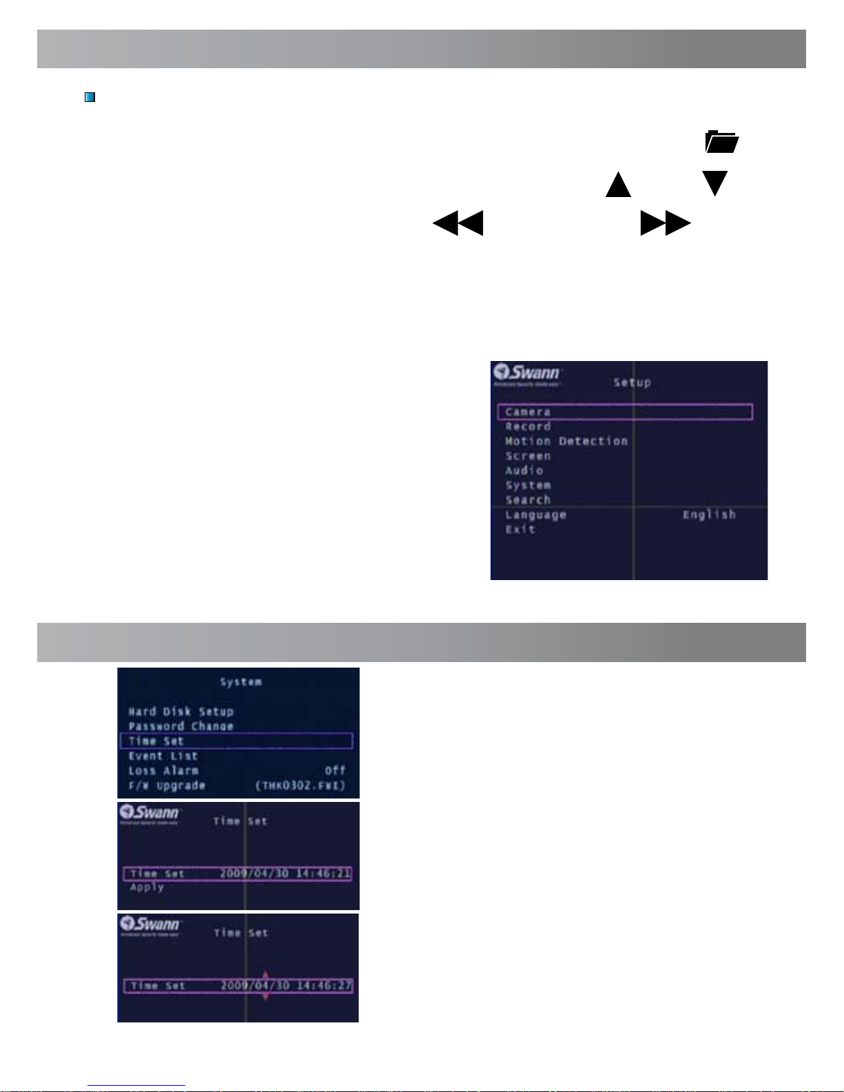
The main Setup Menu can be accessed by pressing the MENU Button
To navigate the menus press the directional arrow keys UP DOWN
To change selections use the REWIND & FAST FOWARD
buttons
To select the highlighted option press the SET button
To return to the previous menu press the MENU button
Note: The menu cannot be accessed
while in playback or backup mode.
Return to the main camera view before
entering the menu.
Main Setup Menu
Setting DVR Time
To change the DVR time, go into the SYSTEM
menu and select TIME SET.
With TIME SET highlighted press the SET
button to display the selection arrows.
Use the FAST FOWARD & REWIND buttons to
select between the date (year, month, day)
and time (hour, minute, seconds)
Using the UP & DOWN buttons change the
selected option
Page 10
1010
Single Camera View
Multi Camera View
5
6
2
3
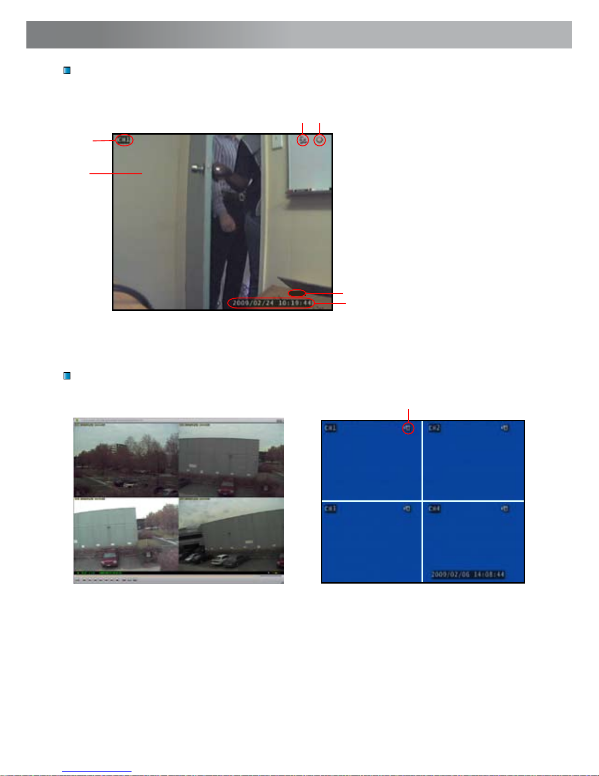
1. Current Camera Channel
2. Motion Detection Icon
3. Recording Icon
4. Main Display
5. Current Date & Time
6. Mute Audio
7. No Camera Signal Icon
Multi Camera View with 4 Cameras Multi Camera View with No Cameras
7
MUTE
Image Display
1
4
Page 11
11
Camera Menu
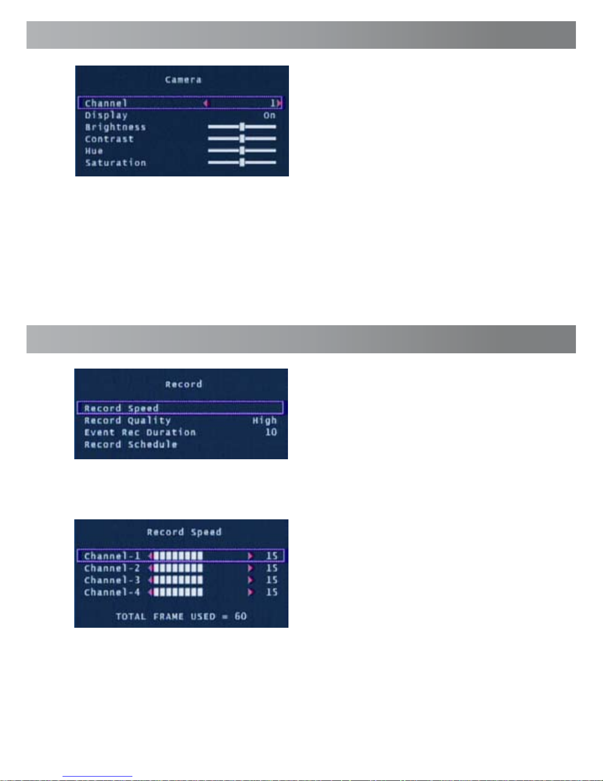
The Camera menu allows you to
change visual attributes on each of the
camera channels.
Channel: Display the attributes of currently selected camera 1-4.
Display: Turn the selected camera On or Off in the main display.
Brightness, Contrast, Hue, Saturation: Using the UP & DOWN buttons high-
light the display option you want to change. Use the FAST FOWARD button to
increase the settings and the REWIND button to decrease them.
The Record Menu adjusts recording
quality, timers and schedules.
You may individually set the Record
Speed of each camera. The total
number of frames used can not exceed
60 for NTSC systems or 50 for PAL
systems. Setting lower frame rates will
consume less hard drive space.
Record Speed: Set the recording frame rate per camera. Note: higher frame
rates provide smoother recordings but use more hard drive space.
Record Menu
Page 12

1212
The Record Schedule allows you to set
the recording mode for each hour of the
day based on a 24 hour clock. Use the
left / right keys to move and up / down
keys to change the current selection.
No Record: will not record
Time Record: will record for the entire
hour
Motion Record: will only record when
motion is detected
Important: To enable Motion Recording you must set the hour to Motion
Record (green) AND set the Sensitivity and Motion Area in the Motion
Detection menu.
Record Quality: Set the image quality of the recordings from Normal, High or
Highest. Note: higher image quality settings use more hard drive space.
Event Rec Duration: When Motion Detection is active, Event Rec Duration is
the length of time in seconds the DVR will record after motion stops, from 5, 10,
15, 20, 25 or 30 seconds. Default is set to 10 seconds.
Record Schedule: Set different recording modes depending on the time of day.
Record Menu (cont)
Motion Detection Menu
The Motion Detection menu allows you
to set motion options for each camera.
Note: The DVR detects motion based
on the level of change in the picture.
Channel: Select which camera attributes to change from camera 1-4.
Sensitivity: Set the amount of movement necessary before motion detection
triggers recording. Set from 1 (most sensitive) to 4 (least sensitive), default Off.
Note: this feature must be set from 1-4 to enable motion recording.
Alarm Duration: Set the length of time the alarm will sound when motion is
detected. Set to Off, 5, 10, 15, 20, 25, 30 seconds or Continuous. Note: If the
Alarm Duration is set to Continuous the alarm will continue to sound until this
setting is changed.
Page 13
13
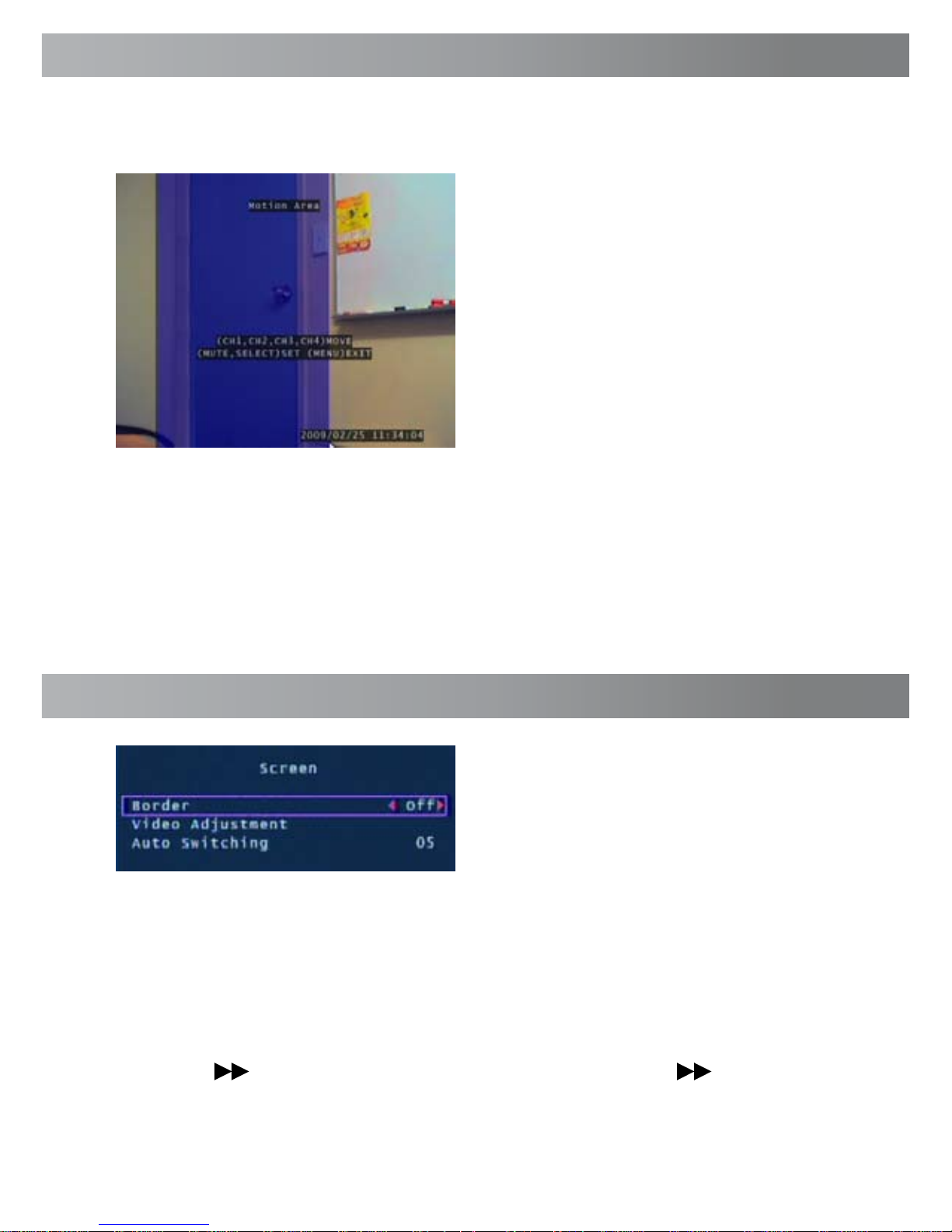
Motion Area: Select the area of the Camera to detect motion. Motion
occurring outside this designated area will not trigger a recording.
Use the UP, DOWN, REWIND & FAST
FOWARD buttons to move the cursor.
Press the SET button to begin to
draw the motion detection area.
Using the arrow buttons draw your
desired motion area and press the
SET button again once complete.
In the example to the left, the blue
motion box is drawn over the door.
Only motion occurring in this area will
trigger recording i.e. the door opening.
This feature is helpful in high traffic areas where only a small portion of the
screen needs to be monitored for example, looking down a driveway with a busy
road next to it.
Important: To enable Motion Recording you must set the Sensitivity, Motion
Area for each camera AND set Motion Record in the Record Schedule menu.
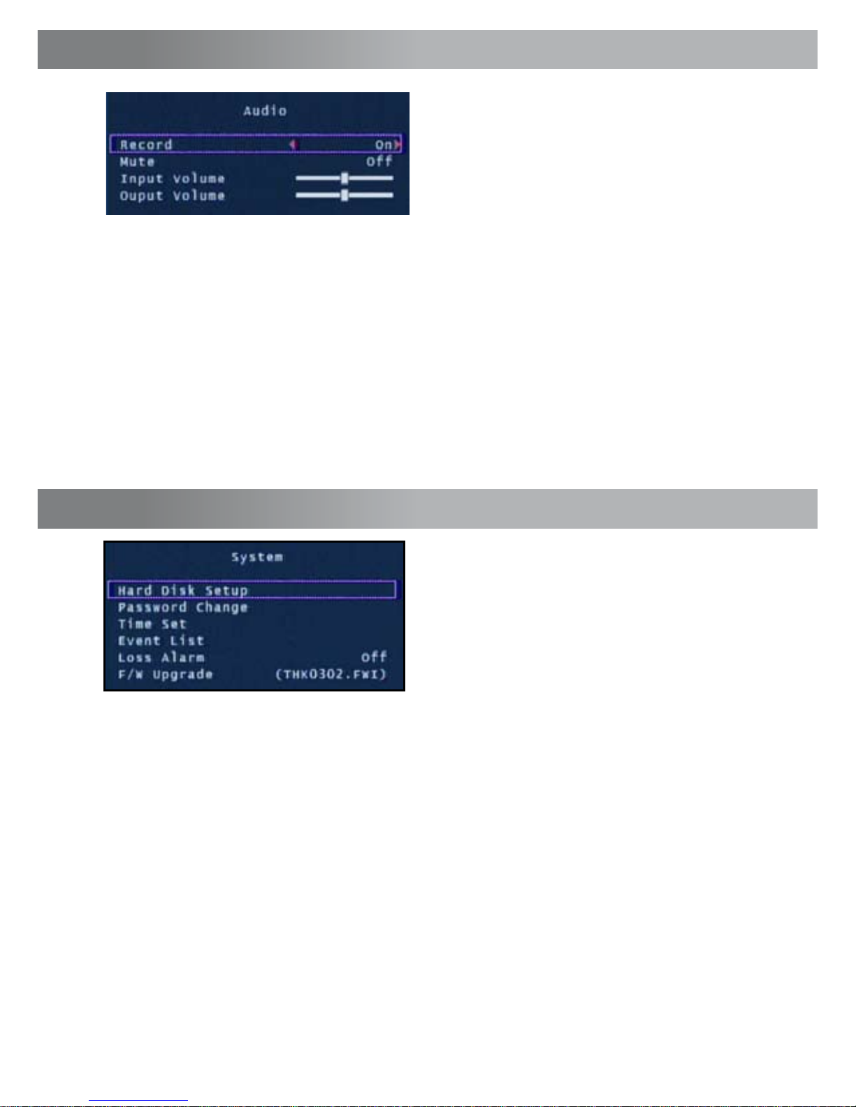
The Screen menu adjusts the display of
cameras in the main camera view.
Border: Applies a border between the cameras in multi camera view.
Video Adjustment: Adjust the display to fit on your TV monitor.
Auto Switching: When active, in live view mode, the DVR will automatically
switch between camera channels in full screen mode. Set the delay from 1-10
seconds between changes or Off. To activate Auto Switching, press the FAST
FORWARD /- button when viewing your cameras. Press the /- button
again to stop Auto Switching.
Screen Menu
Motion Detection Menu (cont)
Page 14
1414
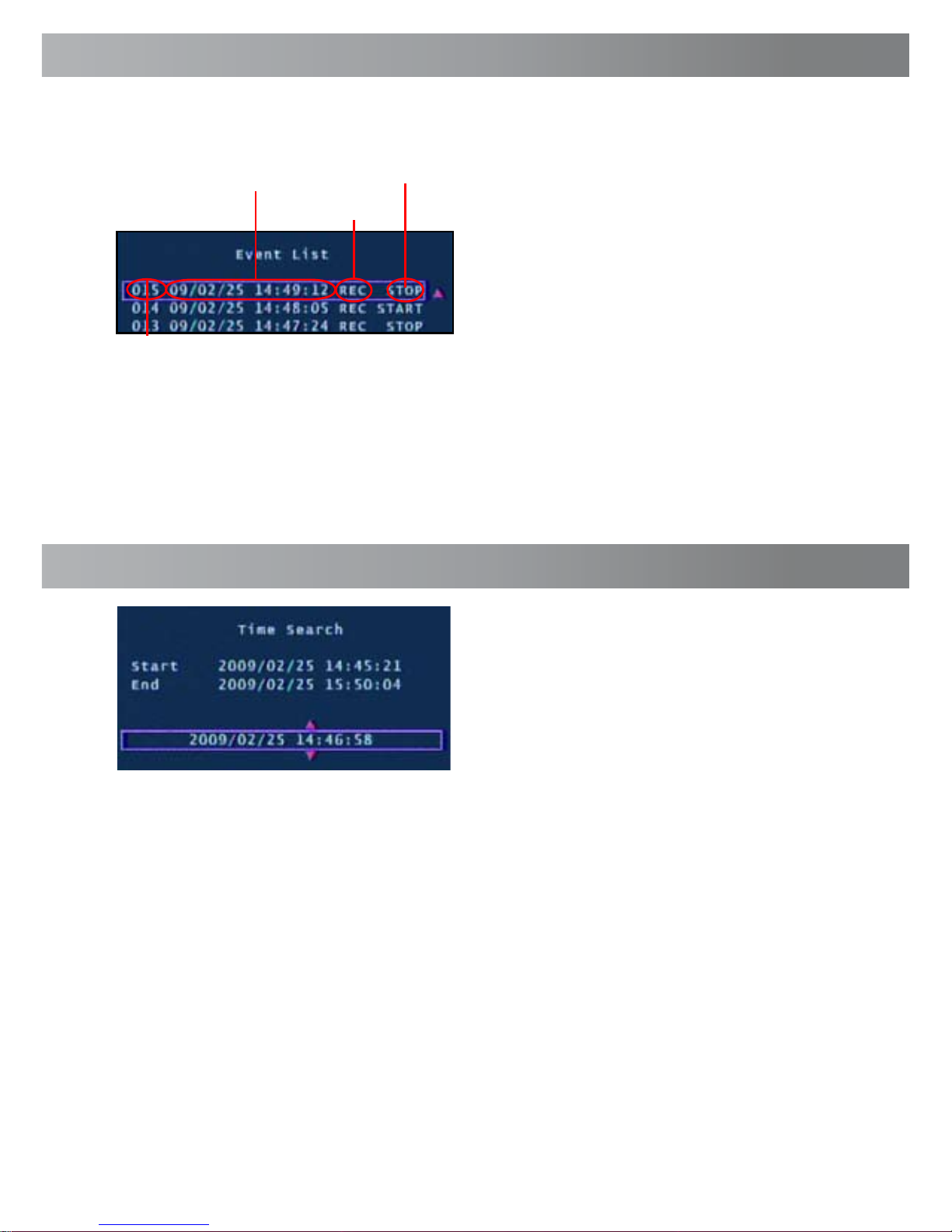
The Audio menu sets the audio
recording and volume options.
Note: You must have a camera with
audio or a powered microphone to
record or monitor audio.
Record: Set to ON to record audio from the Audio Input on the back of the
DVR.
Mute: Turns Audio output on or off when viewing or recording cameras.
Alternatively, press the Mute button to turn Audio on or off while viewing your
cameras.
Input Volume: Move the slider to change the volume of the audio recorded.
Output Volume: Move the slider to change the volume of audio playback.
Audio Menu
System Menu
The System menu provides general
setup options such as hard disk
information, time, date and firmware
settings.
Hard Disk Setup: Display information about the installed hard disk including
total size and memory usage.
Overwrite Enable: If activated, when the hard disk is full the DVR will overwrite
the oldest footage automatically. Default: Yes.
Format HDD: This option will permanently delete all data on the hard disk. The
password must be correctly entered to format the hard disk.
Password Change: This option will change the current password. You will be
prompted to enter the current password, the new password and then confirm
the new password before the change is complete. Note: The default password is
“111111”. If you have lost or forgotten your password contact Swann
Communications Technical Support for assistance.
Page 15
15
Use the arrow buttons to select and
playback the highlighted Event. Press
Stop to exit playback mode.
Hint: You can also access the Event
List by pressing the Play button while
viewing your cameras.
Loss Alarm: When enabled an audible alarm will sound indicating the DVR has
lost the camera signal or a camera has been unplugged.
F/W Upgrade: Displays the current firmware version and allows future
upgrades via a USB Flash Drive. Do not remove the Flash Drive while the firmware is updating as it may damage the DVR. Only use updates authorized by
Swann. When complete, remove the Flash Drive and restart the DVR.
Recording
Number
Date & Time
Recording
Type
Start / Stop
Event
System Menu (cont)
Event List: Displays a list of the last 127 recorded events from the most recent
recording to the oldest. Use the Time Search feature for older events not in list.
Time Search allows you to quickly jump
to a specific time and date to view a
recording.
Start time: This is the date and time of the oldest recording on the DVR.
Stop time: This is the date and time of the final recording on the DVR.
Enter a time between the Start and End time and press the Play button to view a
recording.
Press the Fast Forward and Rewind buttons to quickly scan through recordings.
Press Fast Forward or Rewind multiple times to speed up playback.
Press the Stop button to exit playback mode.
Time Search
Page 16
1616
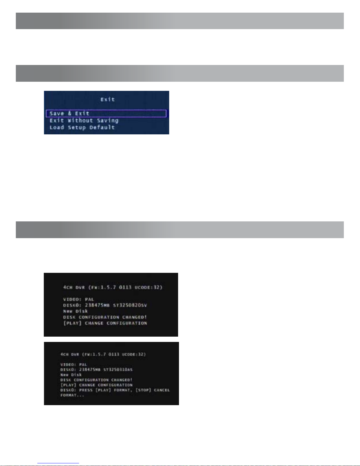
Save, Exit or Load Setup Defaults from the
Exit menu.
Press SET to select the highlighted option.
Save & Exit: Use this option to save all settings that have been changed in the
DVR menus. All changes made will be lost if you do not choose this option.
Exit Without Saving: Select to disregard any changes that have been made
and return to camera view.
Load Setup Default: Reset all settings on the DVR to factory defaults.
Exit Menu
Language
With the Language option selected push the SET button to switch between
English and Chinese.
When starting the Alpha D01 DVR for the first time or starting the DVR after
changing to a new hard drive, the DVR will configure the hard drive for use. Follow the on screen prompts to configure the hard drive.
IMPORTANT NOTE: If format is chosen all existing data on the hard drive will
be deleted and unrecoverable.
1. After the DVR recognizes the new
hard drive press PLAY to configure for
use.
2. When the hard drive is configured
you will be asked to format or cancel.
Press PLAY to confirm the format.
Starting the DVR With a New Hard Drive
Page 17
17
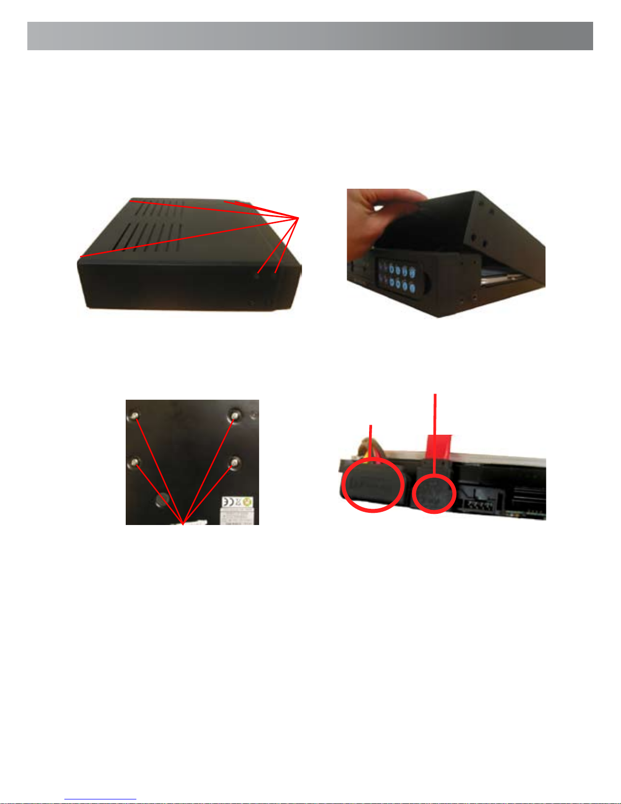
6. Replace the Hard Drive and plug in the SATA and the power cable as shown in
step 5.
7. Screw in the hard drive to the bottom of the case as in step 4.
8. Replace the top of the case.
9. Screw in the remaining screws to the sides and back of the DVR as in step 2.
4. Locate the screws below the hard
drive. Secure the hard drive before removing the 4 screws to avoid damaging
the hard drive
5. Push the metal clip on the SATA
cable (single RED or ORANGE cable)
to unplug the cable from the hard
drive. Unplug the power cable (2
BLACK 1 YELLOW and 1 RED cable)
from the back of the Hard Drive.
Remove
Power Cable
SATA Cable
IMPORTANT NOTE: The following instructions are for installing or changing the
hard drive. If your Alpha D01 DVR already has a hard drive pre-installed disregard these steps.
Installing / Changing a Hard Drive in the Alpha D01 DVR
1. Ensure the Alpha D01 DVR is unplugged and removed from mains power.
2. Locate and remove the 6 screws 2 on
each side at the front and 2 at the top
on the back. (The bottom screws on the
front do not need to be removed.
3. Pull up the top case of the DVR.
Remove
Installing or Changing a Hard Drive
Page 18
1818
Backing Up Footage to PC
The Alpha D01 DVR has a backup feature via the USB port on the back of the
DVR. The DVR accepts most flash drives or thumbdrives. The flash drive / thumbdrive must be formatted to the FAT32 file system. Please see your flash drive’s /
thumbdrive’s instructions regarding formatting. Follow the steps below to backup
footage:
1. Insert a USB flash drive / thumbdrive (not included) to the USB port.
2. Press Play to enter playback mode or use the Time Search feature to find a
recording.
3. Pause playback at the start of the footage you would like to backup.
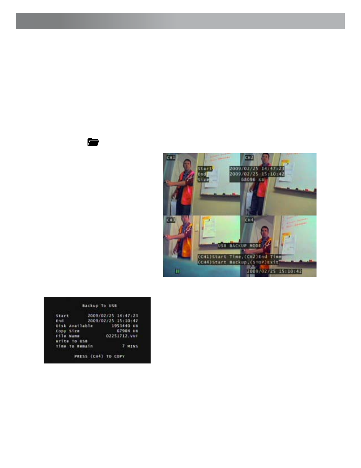
4. Press the Menu / File button to display the USB Backup Mode.
5. Press the CH1 button to
designate the start of a backup
recording.
6. Play and find the end of the
footage you want to backup
and press Pause.
7. Press the CH2 button to
indicate the end of a backup
recording.
8. When you have chosen the
START and END time of the
recording press the CH4 button
to continue.
9. The Backup to USB screen will appear
with details of the USB device inserted, size
requirements and file name. Press CH4 to
begin copying.
10. When the backup is complete press the
Stop button and remove the USB device.
NOTE: USB back up can take up to the same amount of time as playing
back the video on screen. Eg. 1 hour play back may take up to 1 hour to
back up.
WARNING: Do not connect the DVR directly to a computer. Do not
remove the USB Flash Drive while the DVR is copying footage. Damage
may occur to attached devices if used improperly.
Page 19
19
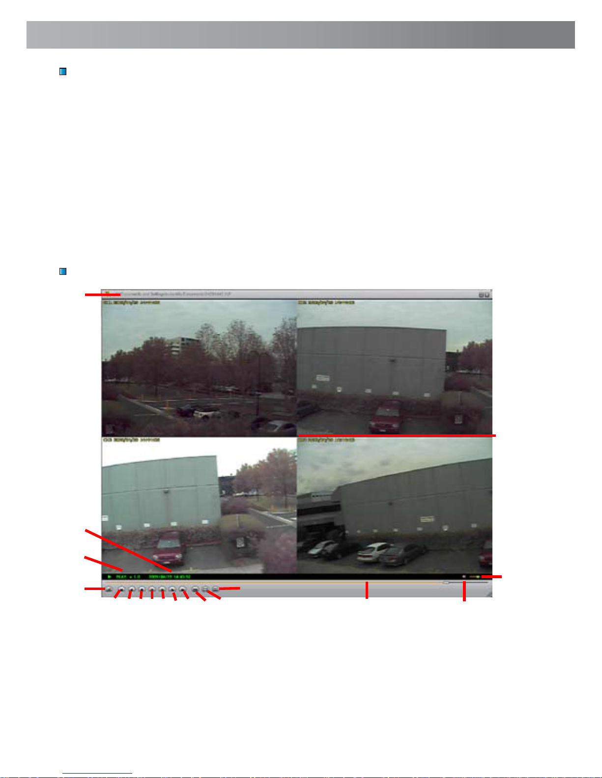
VVFPlayer Interface
View backed up footage from the Alpha D01 DVR with the included VVFPlayer
software located on the CD.
1. Put the CD in the CD drive. If it does not open automatically, click START open
MY COMPUTER and Double click the CD drive.
2. Copy the VVFPlayer_V2_6_4B software from the CD to your computer.
3. Double click to open the VVFPlayer software.
4. Click the File Folder (4) to bring up the open screen. Navigate to the video
you want to view and press Open. The backup file will have a .VVF extension.
5. Use the controls to view the video footage.
Viewing Backup Footage on a PC
Using the VVFPlayer software
1
2
3
4
5 8 126 9 137 10 11 15
16
17
18
14
1. File name
2. Date & time of recording
3. Current play state
4. Open File
5. Fast Reverse (16x, 32x, 64x)
6. Reverse (1x)
7. Previous frame
8. Pause
9. Next frame
10. Play
11. Fast Forward (16x, 32x, 64x)
12. Photo snapshot
13. Single Camera View
14. Split screen view
15. Timeline slider
16. Sound / Mute
17. Volume
18. Camera view
Page 20
2020
Viewing Backup Footage on a PC (cont)
Exporting an AVI file
Extract footage from a larger video clip
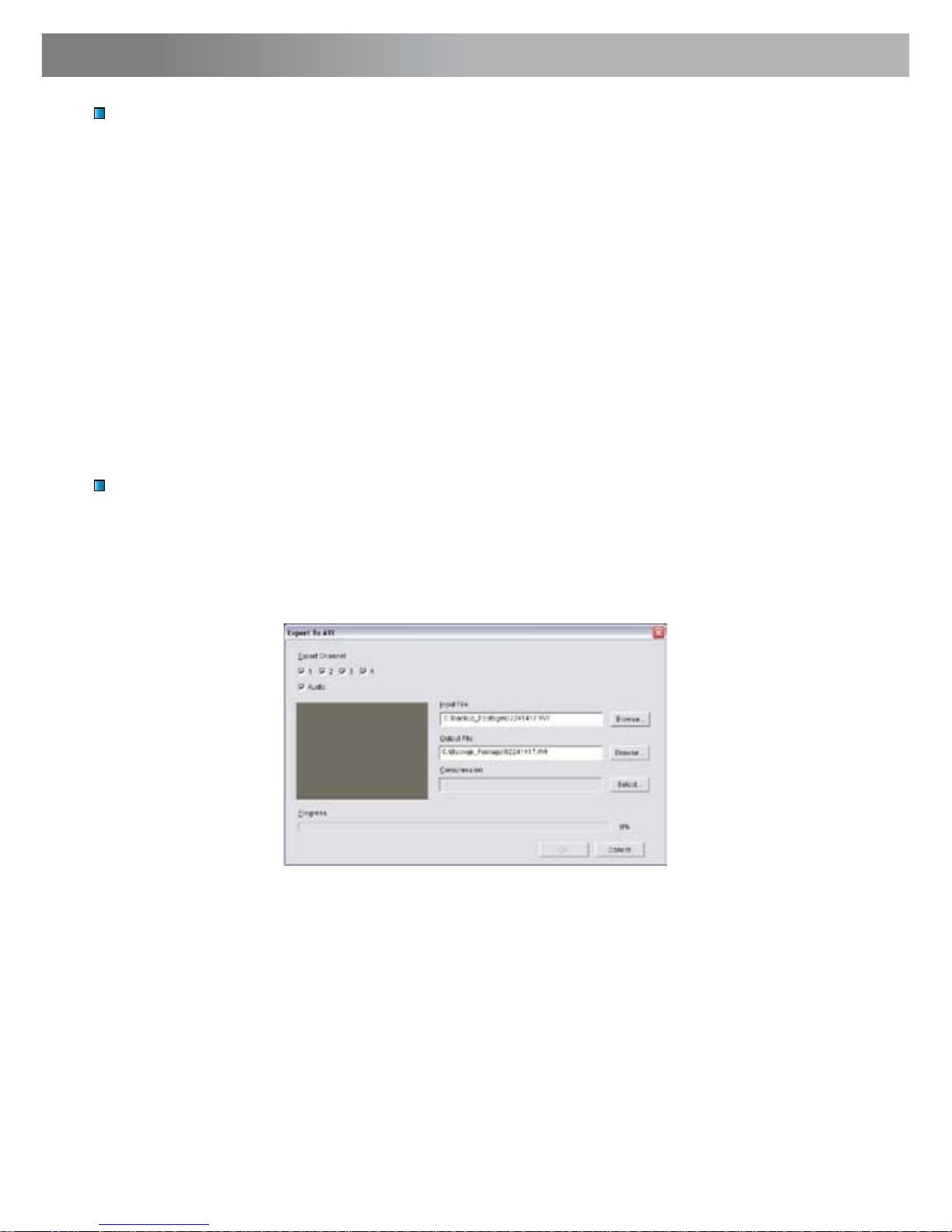
To view video footage on another computer create an AVI file using the built in
export ability.
1. Right-click the main Camera view and click Export > AVI
2. Click “Browse...” next to Input File and select the video you want to convert.
3. Click “Browse...” next to Output File to select a location to export.
4. Choose your preferred compression method by clicking Select... If you are
unsure which method to use, select the default uncompressed mode.
5. Click OK to export the file.
6. Playback the file in your preferred media player.
When dealing with larger backup files it may be necessary to extract smaller clips.
The following describes how to extract footage and export to a new .VVF file.
1. Open and play the clip to extract from.
2. Pause the clip where you want to start the extraction.
3. Right-click the camera view and select Capture > Mark In
4. Find and Pause the clip at the end of the extraction.
5. Right-click the camera view and select Capture > Mark Out
6. Right-click the camera view and select Capture > Export and save the file
name and location. Note this export is in .VVF format.
Page 21

21
Problem: The Power light keeps blinking red.
Solution: Ensure you are using the correct Power Adapter provided for the DVR.
If you have purchased the DVR as part of a kit, make sure the cameras are operating on a separate Power Adapter. The larger power adapter with higher amps
is designed specifically for the DVR.
Problem: The hard drive is not working.
Solution: Ensure the DVR is using the correct Power Adapter supplied. Open
the DVR and ensure the SATA cable is connected to the DVR and Hard Drive.
Problem: The hard drive usage is at 100% and will not record.
Solution: Format the hard drive or set the hard drive to overwrite mode.
Problem: I can only see a blue screen where my camera should be.
Solution: If only 1 camera view is blue, the DVR is not receiving that camera’s
signal. Check that the camera connections on the back of the DVR are secure.
Ensure the camera is plugged in and has power.
Problem: The DVR will not turn on.
Solution: Make sure you are using the correct Power Adapter for the DVR. Try
a second power outlet. Check the connections on the back of the DVR.
Problem: My DVR does not save footage more than a few days old.
Solution: Change the quality settings to Normal, lower the camera frame rates
or enable motion recording to conserve hard drive space.
Problem: I want to format my Hard Drive but I don’t remember the password.
Solution: The default password is “111111”. Swann recommends changing
the default password to prevent tampering or unauthorized use.
Problem: I am using wireless cameras and the DVR keeps beeping and motion
records all the time.
Solution: Analog wireless cameras suffer from interference. The DVR interprets
the change of image as motion and records. Swann recommends the use of wired
cameras or digital wireless cameras such as the ADW-300 for DVR recording.
Problem: I am unable to playback recorded footage.
Solution: Make sure when selecting footage to playback that you have high-
lighted the START time of that footage and not the STOP time
Troubleshooting Guide
Page 22

2222
Video/Audio
Video Format: NTSC / PAL depending on region
Operating System: Embedded RTOS
Video Input: RCA x 4
Audio Input: RCA x 1, Line-In
Video Output: BNC x 1
Audio Output: RCA x 1, Line-Out
Display and Recording
Display Frame: NTSC: 120 fps (4 × 30 fps)
PAL: 100 fps (4 × 25 fps)
Global Recording Frame Rate: NTSC: Max. 60 fps
PAL: Max. 50 fps
Video Operation Duplex : Record, Playback
Display Resolution: NTSC: 640 x 448
PAL: 640 x 544
Recording Resolution: NTSC: 640x224
PAL: 640x272
Compression Format: Modified MJPEG
Size per frame: Normal: 12K Bytes
High: 15K Bytes
Highest: 20K Bytes
General
HDD Interface: SATA HDD x 1
Backup Method: USB Flash Drive, Thumbdrive (up to 2GB max)
Search Mode: Time/Date, Event
Full Screen: Yes
Motion Detect: Yes
Loss Detect: Yes
Auto Switching: Yes
Buzzer Output: Yes
Brightness Adjust: Yes
Contrast Adjust: Yes
Recovery Mode: Auto Restore Record on power failure
DC Input: DC 12V
Dimensions: 8.9” x 8.2” x 2.1”
225mm X 208mm X 53mm
Weight: 2.8lbs
1.3kg
Technical Specifications
Page 23

23
Warranty Information
Swann Communications warrants this product against defects in workmanship
and material for a period of one (1) year from it’s original purchase date. You must
present your receipt as proof of date of purchase for warranty validation. Any unit
which proves defective during the stated period will be repaired without charge
for parts or labour or replaced at the sole discretion of Swann. The end user is
responsible for all freight charges incurred to send the product to Swann’s repair
centres. The end user is responsible for all shipping costs incurred when shipping
from and to any country other than the country of origin.
The warranty does not cover any incidental, accidental or consequential damages
arising from the use of or the inability to use this product. Any costs associated with
the fitting or removal of this product by a tradesman or other person or any other
costs associated with its use are the responsibility of the end user. This warranty
applies to the original purchaser of the product only and is not transferable to any
third party. Unauthorized end user or third party modifications to any component
or evidence of misuse or abuse of the device will render all warranties void.
By law some countries do not allow limitations on certain exclusions in this warranty.
Where applicable by local laws, regulations and legal rights will take precedence.
Limited Warranty Terms & Conditions
Swann Communications USA Inc.
12636 Clark Street
Santa Fe Springs CA 90670
USA
Swann Communications
Unit 13, 331 Ingles Street,
Port Melbourne Vic 3207
Swann Communications LTD.
Stag Gates House
63/64 The Avenue
SO171XS
United Kingdom
Page 24
SWA11
www.swannsecurity.com
Alpha Indoor / Outdoor
Security Camera
Night Vision 30ft / 9m
Operating Instructions
Page 25

22
FCC Verification:
NOTE: This equipment has been tested and found to comply with the limits for
Class B digital device, pursuant to part 15 of the FCC Rules. These limits are designed to provide reasonable protection against harmful interference in a residential installation. This equipment generates, uses and can radiate radio frequency
energy and, if not installed and used in accordance with the instructions, may
cause harmful interference to radio or television reception, which can be determined by turning the equipment off and on, the user is encouraged to try to correct the interference by one or more of the following measures:
· Reorient or relocate the receiving antenna
· Increase the separation between the equipment and the receiver
· Connect the equipment into an outlet on a circuit different from that to which
the receiver is connected
· Consult the dealer or an experienced radio/TV technician for help
IMPORTANT: Prohibition against eavesdropping.
Except for the operations of law enforcement officers conducted under lawful
authority, no person shall use, either directly or indirectly, a device operated pursuant to the provisions of this Part for the purpose of overhearing or recording the
private conversations of others unless such use is authorized by all of the parties
engaging in the conversation.
WARNING: Modifications not approved by the party responsible for compliance
could void user’s authority to operate the equipment.
IMPORTANT SAFETY INSTRUCTIONS:
· Make sure product is fixed correctly and stable if fastened in place
· Do not operate if wires and terminals are exposed
Before you begin
Page 26
3
Table of Contents
Package Contents
Before You Begin 2
Table of Contents 3
Package Contents 3
Connection Guide 4 - 5
Viewing the Camera on Your TV or VCR 6
Tips & Suggestions 6
Troubleshooting Guide 7
Helpdesk / Technical Support Details Rear Cover
Warranty Information Rear Cover
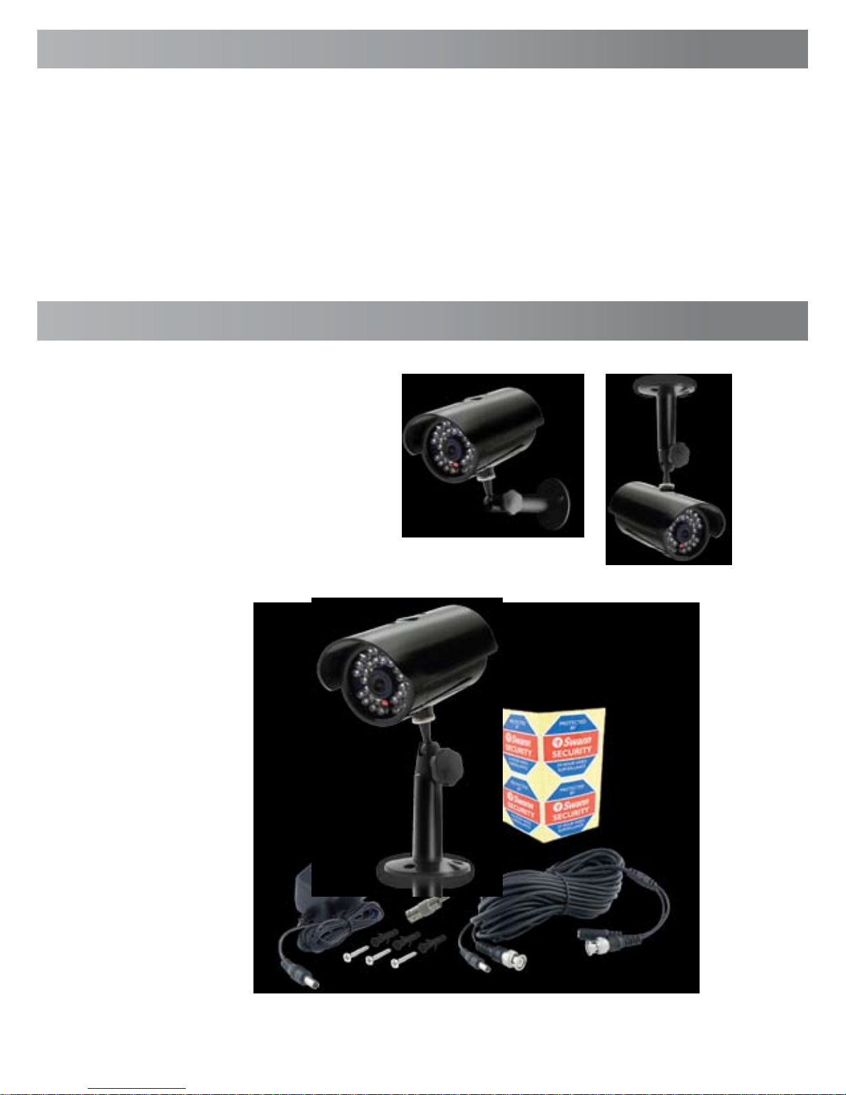
Single Camera Pack
1 x Alpha Security Camera•
1 x Camera Stand•
1 x BNC Extension Cable•
1 x BNC to RCA Adapter•
1 x Power Adapter•
1 x Operating Instructions•
4 x Security Stickers•
Mounting Hardware•
Page 27
44
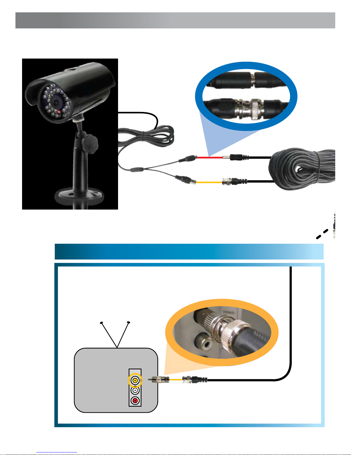
Connection Guide
INPUT
2A. Connecting Directly to TV 2B. Connecting to Your Existing DVR
Connect the BNC to RCA
Adapter and connect to Video
Input on your TV or VCR
2
Connect the camera’s DC
and BNC socket cable to the
extension cable’s DC and BNC plugs
1
3A
3B
Page 28
5
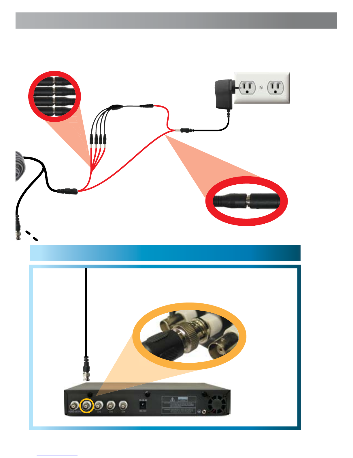
Connect the BNC Extension
Cable to an open channel on
the back of the DVR
2
Plug in the camera
power adapter into
a wall socket
4
FOR A SINGLE CAMERA
Connect the extension cables
DC socket to the DC plug on
the power adapter
3A
FOR 4 CAMERA PACKS
Connect the extension cables
DC socket to one of the four
sockets on the power splitter.
Then, plug the single end of the
power splitter to the DC plug
on the power adaptor.
3B
Page 29

66
Viewing the Camera on Your TV or VCR
Tips & Suggestions
Viewing the Alpha Security Camera on a TV
After connecting the Alpha Security Camera directly to your TV and powering it
on as described on page 4, tune the TV to the correct input channel.
On your TV’s remote control, the input button is usually labelled as Input, Source,
A/V, Channel 0, AUX etc.*
Viewing and Recording the Alpha Security Camera on a VCR
Connect the Alpha Security Camera into an available input channel on your VCR
in the same manner as the TV connection listed on page 4. Turn on your VCR
and TV as if you were about to play a VCR tape.
On your VCR’s remote control, find the input button with is usually labelled as L1,
L2, Input, Source, A/V, Channel, 0, AUX etc.* Insert a tape and push record to
record the camera.
*Consult the TV or VCR instruction manual for details about changing input
channels
Never aim the camera directly at the sun as it may damage the sensor
Test all connections and ensure the camera is working correctly prior to permanent
installation
Install cameras high enough or out of reach to avoid tampering
Place Security Stickers in a visible location to alert potential thieves they are being
monitored
Mix real cameras with dummy cameras to give the impression of increased security
coverage
Purchase a Swann DVR to record multiple cameras simultaneously and easily monitor your property.
Place cameras in high traffic areas such as doorways to maximise security
Use only the included Power Supply and do not modify or cut wires
Page 30

7
Troubleshooting Guide
Technical Specifications
Problem: I can’t see the camera on my TV.
Solution: Ensure the camera is plugged in and the TV or VCR is tuned to the
correct input channel.
Problem: When I view my camera at night I only see a bright spot and no image.
Solution: Night Vision will reflect when shining through a window. Move the
camera to the other side of the window or another location.
Problem: The BNC Extension Cable will not connect to my TV.
Solution: Connect the BNC to RCA adapter to the end of the Extension Cable
and plug into the TV.
Problem: On my Swann DVR, Video Loss appears where my camera should be.
Solution: Check the Extension cable is securely connected to the camera and
check the connection is secure on the back of the DVR. Also ensure the camera
has power by trying a second power outlet.
Video
Image Sensor 1/3” Color Super CMOS
Video Quality 400 TV Lines
Number of Effective Pixels NTSC: 510 x 492 / PAL: 628 x 582
Minimum Illumination 0 Lux (IR on)
Day/Night Mode Color during day / switches to B&W night
White Balance Automatic
Signal / Noise Ratio > 50dB
Electronic Shutter 1/60 - 1/15,000 NTSC / 1/50 - 1/15,000 PAL
Gain Control Automatic
Backlight Compensation Yes
Lens 6mm
Viewing Angle 53 degrees
Night Vision
Number of Infra-Red LEDs 30
Infra-Red Wavelength 850nm
Night Vision Distance Up to 30ft / 9m
Infra-Red LED Life 10,000 hours
General
Operating Power DC 12V
Operating Temperature -10°C ~ 50°C / 14°F ~ 122°F
Body Construction ABS Plastic
Dimensions - Camera 5.5” x 2.8” x 2.8” / 140mm x 70mm x 70mm
Dimensions – Stand 4.5” x 2.3” x 2.3”/ 120mm x 60mm x 60mm
Weight – Camera & Stand 0.5lbs / 235g
Page 31
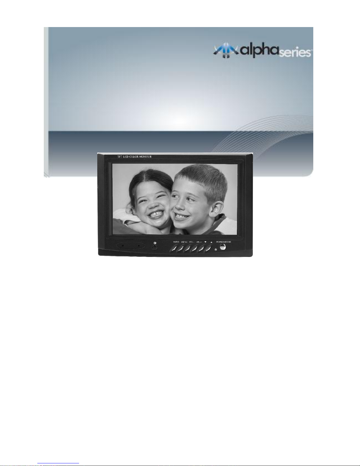
Operation Instructions
7” LCD Colour monitor
Operating Instruction
Swann Security
www.swannsecurity.com
Page 32

Table of Contents
Important Information regarding remote control ........... 1
1. Precautions ...............................................1
2. Accessories............................................................ 2
3. Appearance ...............................................3
4. Description of Buttons on Remote Control ............. 4
5. Basic Operation Methods ..............................................5
6. Menu Operation ........................................... 6
6.1. PICTURE ........................................ 6
6.2. OPTION .........................................6
6.3. CLOCK ...............................................7
6.4. SYSTEM ....................................................... 7
7. Before you request a replacement ...................... 8
8. Technical Parameters ....................................................9
Page 33

Important information regarding remote control
IR Remote Control
The LCD monitor and DVR in this kit both use similar IR signals
from the remote controls. This means that when using the DVR
remote to control the DVR itself, some of the DVR’s remote buttons
will also have an effect on the LCD screen. To prevent the
annoyance of accidental changing of the input mode the LCD
screen has had the Remote-control receive window covered with a
small piece of black tape. Please ensure you remove this tape
before changing any of the LCD screen settings and then replace it
once you are finished. If the tape is lost simply replace it with similar
black tape or cover it with your hand or other object while using the
DVR remote. Leaving the Remote-control receive window
uncovered will not result in any damage to the LCD screen.
1. Precautions
Storage
1. Keep this product away from extremely hot or cold places. The
storage temperature ranges from -20 to 60 and the working
temperature from 0 to 40 .
2. Do not use this product near a damp environment like bathtubs, wash
basins, kitchens, washtubs, as well as basements, swimming pools or
similar places.
3. Do not expose your Monitor to high humidity, dust or oil smoke.
4. Do not throw or drop this product.
5. Do not subject this device to an enclosed space or strong vibrations, avoid
heavy impact.
6. Do not push on or scrub this product with sharp objects.
Maintenance
1. Disconnect all cables from this device at first before cleaning.
2. Wipe the enclosure, screen and keys using a damp soft cloth with a
little mild detergent.
3. Do not use polishing cloth, abstergent and or any types of propellants or chemical
detergents like alcohol and benzene to clean your device.
-1-
Page 34
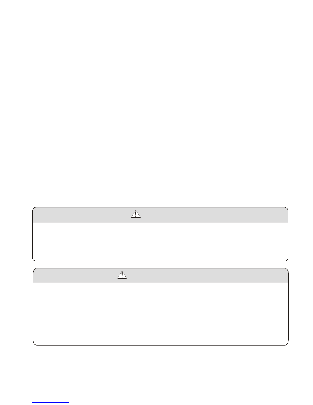
2. Accessories
1. Car adapter
2. AC adapter
3. Remote control
4. AAA type batteries
5. AV conversion cable
6. Base support
7. Operating Instructions
* If any of the contents are missing from your package please contact
Swann for assistance.
Warning!
1. While driving do not watch programs or turn your Monitor on for your
own and others' safety.
2. It is very dangerous to watch programs or operate the Monitor while
driving or parking.
Special Notice
Bright spots or dark spots may appear on the screen. This is a normal
phenomenon associated with the active matrix display technology and is not
a sign of malfunction. For any failures, please turn off your Monitor
immediately and contact Swann. This device integrates a great deal of fine
electronic components. Disassembly or alteration may result in damage or
breakage not covered by warranty.
-2-
Page 35
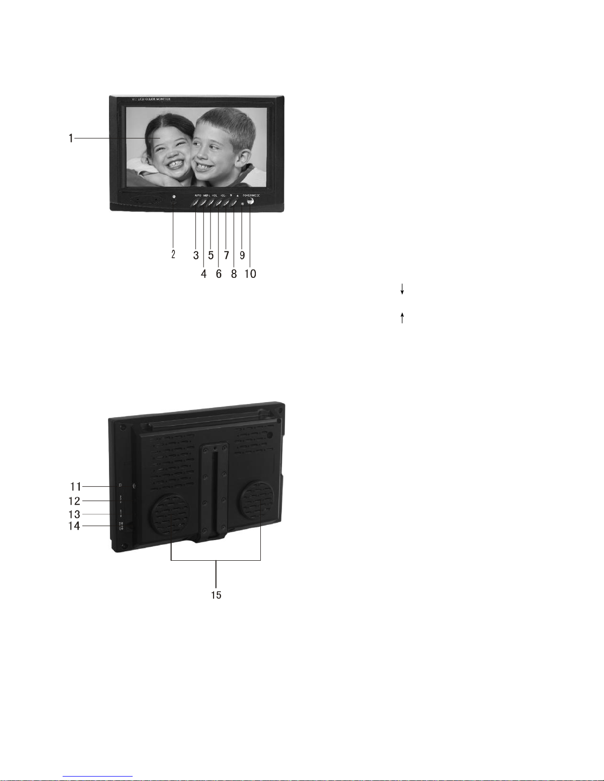
3. Appearance
1. TFT-LCD screen
2. Remote-control receive window
3. AUTO: AV auto switch interval
setting
4. MENU: Menu button
5. Volume-, selection-
6. Volume+, selection +
7. Selection
8. Selection
9. Power indicator Red:
Standby Green: Power-on
10. POWER/MODE:
Standby/AV1/AV2 switch
11. Headphone jack
12. AV2 IN jack
13. AV1 IN jack
14. DC Input jack
15. Speaker
-3-
Page 36

4. Description of Buttons on Remote Control
VOL - / + (Volume adjust)
Press VOL - , the audio volume decreases.
Press VOL +, the audio volume increases.
MUTE (Mute): Press this button, sound disappears, press it again or
VOL+ to resume normal sound.
MENU (Menu button):Press this button to display the following four
submenus: PICTURE, OPTION, CLOCK and SYSTEM.
POWER (Standby/On):
Press this button to switch between "Standby" mode and "ON".
MODE (Mode): By pressing this button, users can choose one of the five
picture modes of Standard, Soft, Vivid, Light and Personal.
CALL (Call):
Press this button to display the AV Input currently selected.
TIMER: Press this to set sleep off, to automatically turn off the screen
after up to 120 minutes.
LANG: Press this button to select multi language of OSD. CALE:
Press this button to show Year, Month, Day and Week.
Press / to adjust the Year, press VOL - / VOL + to adjust the
Month.
AV: Press this button to switch between AV1/AV2/Auto switch input modes.
: Press this button to flip the picture horizontally, and press it again to
return to the original image.
: Press this button to flip the picture vertically, and press it again to return
to the original image.
: (LCD Display Mode) Two screen modes are supported, either 16:9 or 4:3.
We recommend 4:3 for use with the DVR.
-4-
Page 37
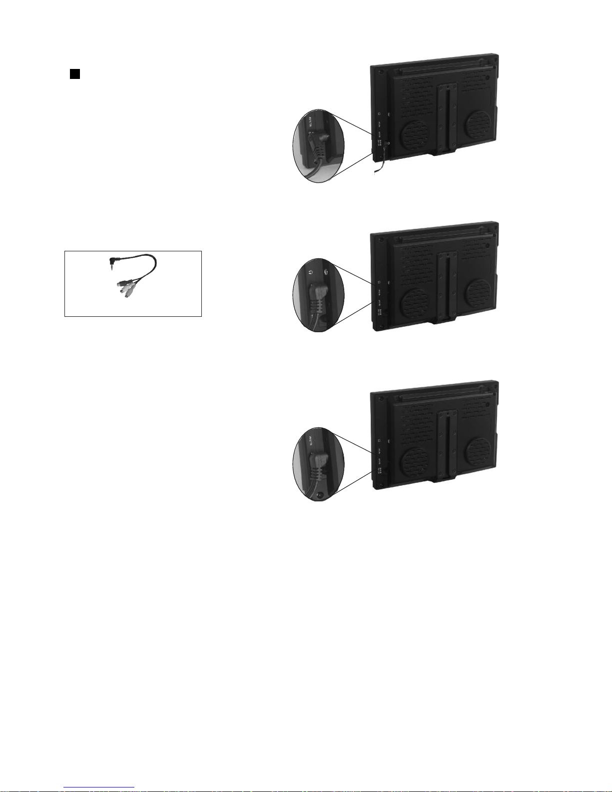
5. Basic Operation Methods
Basic interface connection
5.1 Connection of Power Supply:
Align the power supply plug on AC
adapter with the jack on the machine
rear cover marked with DC.
5.2 Connection of AV converter Cable:
AV converter cable
Insert the external video out cable into
the yellow port of the AV converter cable, the left
audio out cable into the white port and the right
audio out cable into the red port. Then plug the
AV converter cable in to AV1/IN or AV2/IN jack
on the side of the monitor as shown.
-5-
Page 38

6. Menu Operation
Press MENU to display options as follows:
PICTURE OPTION CLOCK
SYSTEM
6.1. PICTURE
CONTRAST, BRIGHT, COLOR, SHARP and TINT displays on the screen as
per the description below:
Press or to select the item, Press or to adjust
Notice
The TINT option in the Picture menu will only show when displaying an
image using the NTSC video system used in the USA.
6.2. OPTION
LANGUAGE, CALENDAR, GAME and AUTO CHANGE SOURCE
displays on the screen as per the des crip tion b elow:
6.2.1. Press ▲ or ▼ to select the item LANGUAGE:
Press ◄ or ► to select multi language of OSD.
6.2.2. Press ▲ or ▼ to select the item CALENDAR:
Press ◄ or ► to select CALENDAR. Press ▲ or ▼ to adjust year, and
Press ◄ or ► to adjust month.
6.2.3. Press ▲ or ▼ to select the option GAME:
Press ◄ or ► then game begins, then press ◄ to move leftward, ► to rightward, ▼
to quick down and ▲ to rotate the game by 360 degrees.
Press POWER to exit game and return to VIDEO status.
6.2.4. Press ▲ or ▼ to select the item AUTO CHANGE SOURCE:
Press ◄ or ► to adjust monitor auto switch AV1/AV2 interval setting of 4 seconds, 6
seconds, 8 seconds an off.
-6-
Page 39
6.3. CLOCK
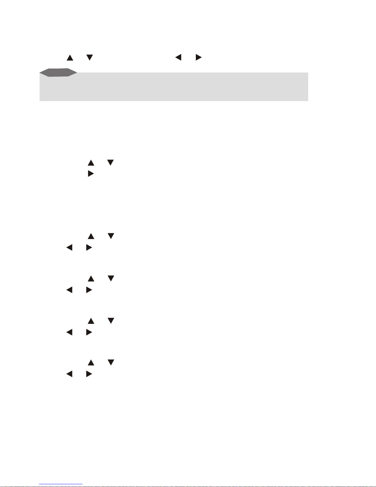
TIME, ON-TIME, OFF-TIME, ATTENTION, will display on the screen as described
below:
Press or to select item, Press or to setup.
Notice
If you wish to setup the other options, TIME must be setup first. All options
are able to be set a maximum of 24 hours ahead.
6.4. SYSTEM
COLOR-SYS, BLUE BACK, HORIZONTAL, VERTICAL and ZOOM
displays on the screen as below description:
6.4.1.Press or to select the option COLOR-SYS:
Then press to revolve the screen in the order of AUTO, PAL and
NTSC. Please choose this system correctly or you may cause image
problems and the screen will show incorrect colours.
We recommended you select the AUTO position so that the type of video input
is automatically detected.
6.4.2.Press or to select the option BLUE BACK:
Press or can select whether the screen shows BLUE BACKGROUND
when there is no signal.
6.4.3.Press or to select the option HORIZONTAL:
Press or to flip the HORIZONTAL image, press again to return to the
default picture.
6.4.4.Press or to select the option VERTICAL:
Press or to flip the VERTICAL image, press again to return to the default
picture.
6.4.5.Press or to select the option ZOOM:
Press or to select the option of picture modes:4:3 mode, and 16:9 mode.
-7-
Page 40
7. Before you request a replacement
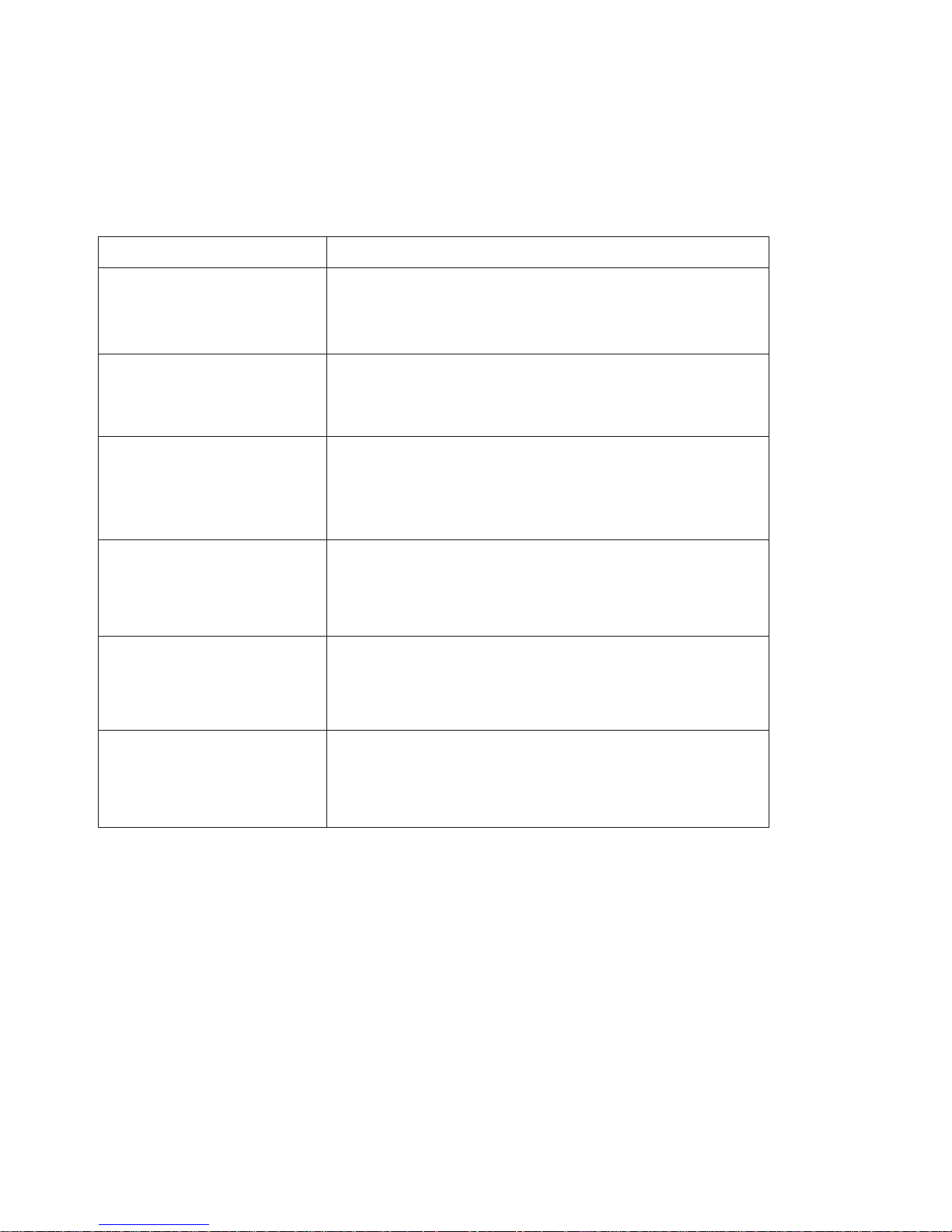
Any of the issues noted below do not necessarily mean failure of the monitor.
Please check following and contact Swann support before you request a repair
or replacement.
Problem
Possible Causes
No picture, no sound
Improper connection with CAR adapter.
Use of incorrect power supply. The power
switch is in the Off position.
No image
AV cord is incorrectly plugged or wrong AV
input is selected?
No sound
Audio cord incorrectly plugged or wrong
AV input is selected, or the sound volume
is turned off or turned down to minimum.
Dark picture
The brightness and contrast have been
adjusted incorrectly; or the environment
temperature is too low.
No color
The colour settings are incorrectly adjusted.
The COLOR-SYS is set to NTSC instead of
PAL.
Upside down or
horizontal
inverted picture
Improperly adjusted Horizontal or Vertical
setting using the remote control.
-8-
Page 41
8. Technical Specifications
Product Name: 7” LCD Colour monitor
Display Device: Colour TFT-LCD
Screen Size: 7 inches diagonal
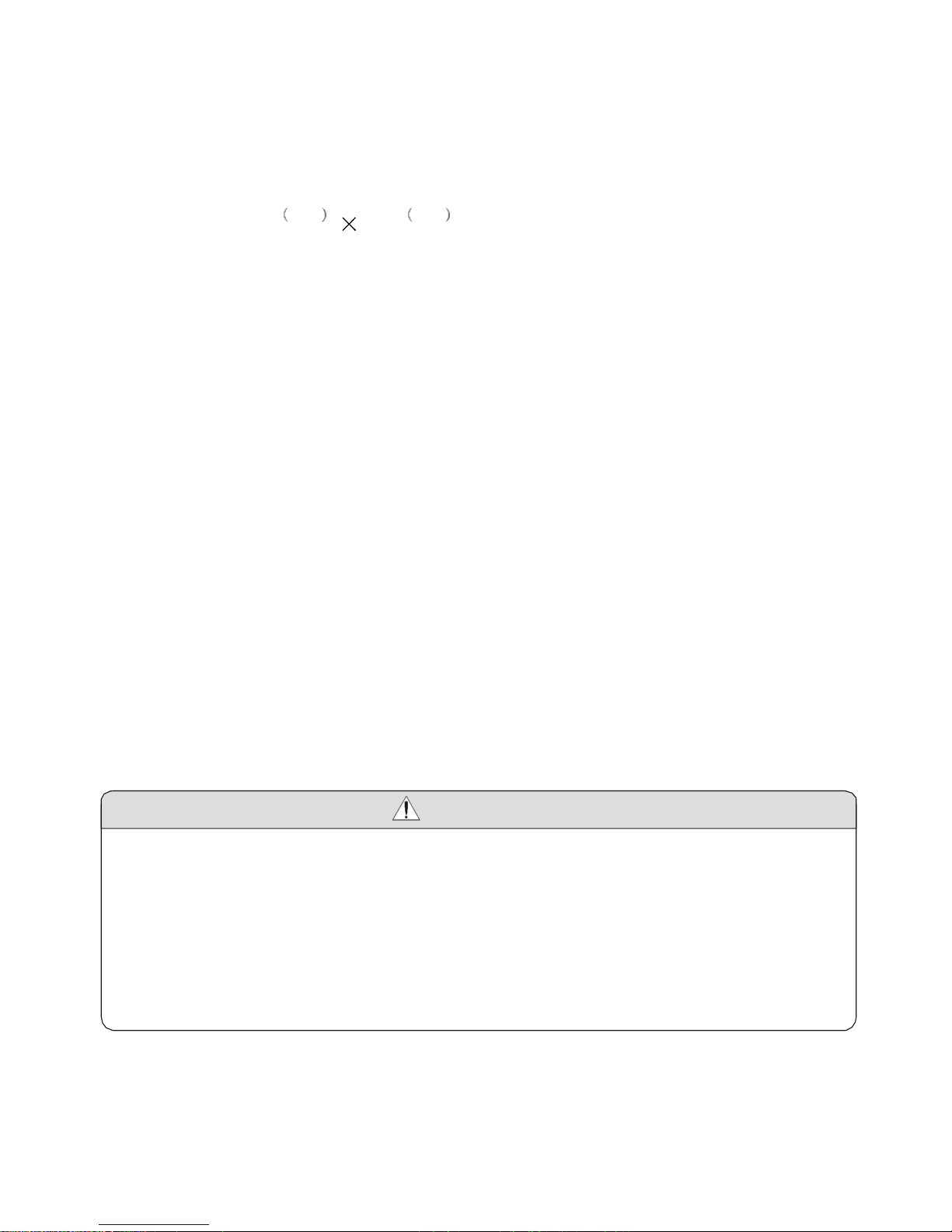
Resolution: 1440 H 234 V
Contrast:
300:1
Brightness:
300cd/m2
Response time:
R:15ms / F: 20ms
Viewing angle:
U:40° / D:60° L/R:60°
Video Input:
1V P-P 75 Ohm composite video signal x 2 (AV1 – AV2)
Audio Input:
1.5V P-P Stereo (Left & Right channel) x 2 (AV1 – AV2)
Audio Output: >0.3W x 2CH - two 4.0cm round inbuilt speakers + external
speakers / headphone jack
Connecting Terminal: Headphone jack, Audio / Video (AV) input jack, External
power supply jack
Applicable Power Supply: Car adapter / DC power adapter @ 12V
Power Consumption: approximately 10W
Operating Temperature: -10°C ~ 50°C (14°F ~ 122°F)
Outer Dimension: 196mm X 130mm X 41mm (7¾” x 5¼” x 1½”)
Weight: 410g (1lb)
Warning!
This product does not contain any user repairable components. Do not try to
dismantle or alter the unit in any way. Maintenance and adjustment of the unit
should only be performed by professionals.
Failure to operate the monitor in the proper manner or any unauthorised
changes or modifications will void the product warranty.
-9-
Page 42

© Swann Communications 2010
Swann Technical Support
All Countries E-mail: [email protected]
Telephone Helpdesk
See http://www.worldtimeserver.com for information on time zones and the
current time in Melbourne, Australia compared to your local time.
USA toll free
1-800-627-2799
(Su, 2pm-10pm US PT)
(M-Th, 6am-10pm US PT)
(F 6am-2pm US PT)
USA Exchange & Repairs
1-800-627-2799 (option 1)
(M-F, 9am-5pm US PT)
AUSTRALIA toll free
1300 138 324
(M 9am-5pm AUS ET)
(Tu-F 1am-5pm AUS ET)
(Sa 1am-9am AUS ET)
NEW ZEALAND toll free
0800 479 266
UK
0203 027 0979
 Loading...