

Swann ADW-340 Instruction Manual
1
INSTRUCTION MANUAL
EN
Digital Wireless
Security System
ADW-340

2
Warranty Information, Verications & Warnings
Swann Communications warrants this product against defects in workmanship and material for a period
of one (1) year from its original purchase date. You must present your receipt as proof of date of purchase
for warranty validation. Any unit which proves defective during the stated period will be repaired without
charge for parts or labour or replaced at the sole discretion of Swann. The end user is responsible for all
freight charges incurred to send the product to Swann’s repair centres. The end user is responsible for all
shipping costs incurred when shipping from and to any country other than the country of origin.
The warranty does not cover any incidental, accidental or consequential damages arising from the use
of or the inability to use this product. Any costs associated with the tting or removal of this product by
a tradesman or other person or any other costs associated with its use are the responsibility of the end
user. This warranty applies to the original purchaser of the product only and is not transferable to any
third party. Unauthorized end user or third party modications to any component or evidence of misuse
or abuse of the device will render all warranties void.
By law some countries do not allow limitations on certain exclusions in this warranty. Where applicable
by local laws, regulations and legal rights will take precedence.
For Australia: Our goods come with guarantees which cannot be excluded under Australian Consumer
Law. You are entitled to a replacement or refund for a major failure and for compensation for any other
reasonably foreseeable loss or damage. You are also entitled to have the goods repaired or replaced if the
goods fail to be of acceptable quality and the failure does not amount to major failure.
Warning
Modications not approved by the party responsible for compliance could
void user’s authority to operate the equipment.
IMPORTANT SAFETY INSTRUCTIONS
• Make sure product is xed correctly and stable if fastened in place
• Do not operate if wires and terminals are exposed
IMPORTANT NOTE: All jurisdictions have specic laws and regulations relating to the use of cameras.
Before using any camera for any purpose, it is the buyer’s responsibility to be aware of all applicable laws
and regulations that prohibit or limit the use of cameras and to comply with the applicable laws and
regulations.
FCC Verication
NOTE: This equipment has been tested and found to comply with the limits for Class B digital device,
pursuant to part 15 of the FCC Rules. These limits are designed to provide reasonable protection against
harmful interference in a residential installation. This equipment generates, uses and can radiate radio
frequency energy and, if not installed and used in accordance with the instructions, may cause harmful
interference to radio or television reception, which can be determined by turning the equipment o and
on, the user is encouraged to try to correct the interference by one or more of the following measures:
• Reorient or relocate the receiving antenna
• Increase the separation between the equipment and the receiver
• Connect the equipment into an outlet on a circuit dierent from that to which the receiver is
connected
• Consult the dealer or an experienced radio/TV technician for help
These devices comply with part 15 of the FCC Rules. Operation is subject to the following two conditions:
• These devices may not cause harmful interference, and
• These devices must accept any interference received, including interference that may cause
undesired operation.

3
Contents
Introduction
Warranty Information, Verifications & Warnings 2
Contents 3
Introduction 4
Layout: Side/Rear of the Receiver 5
Layout: Front of the Receiver 6
Layout: The Camera 7
Basic Setup
Setup Guide 8
Menu: System Setup 9
Advanced Configuration
Menu: Camera Setup 12
Menu: Record Setup 13
Menu: Event List / Playback 17
Menu: Miscellaneous 18
Playback: Play video on a PC 20
Reference
Mounting Guide 21
Tips & Tricks: Getting the most out of your ADW-340 22
Troubleshooting: Cameras & Receiver 23
Helpdesk / Technical Support Details 24

4
Introduction
Congratulations on your purchase of this
Digital Wireless Security System from Swann.
Yes, the word “system” is there on purpose: by using the clarity and robust nature of digital
transmission technology paired with a built-in receiver, recorder and monitor, we think you’ve
just acquired one of the best stand-alone wireless CCTV solutions available.
You’ve picked a versatile and easy to use security solution which can be quickly and easily
congured to service your unique needs. Best of all, there’s no need to poke holes in walls to
run cables!
How to proceed from here:
• Check out the IMPORTANT INFORMATION below. We don’t mean to be dramatic, this is
just stu you should know about the ADW-340 so it doesn’t surprise you later.
• Take a moment to appreciate that you’re not trying to install video cables into walls or
ceiling cavities. Perhaps make a cup of tea or coee with your free time?
• Read on through the layout section, and familiarise yourself with the various ports,
connections and buttons. Drink the tea or coee you made a moment ago.
• Then, look at “Setup Guide” on page 8.
IMPORTANT INFORMATION: Read this before proceeding.
• Not all MicroSD cards are supported.
We cannot guarantee universal compatibility. The unit has been tested with many well-known
brands such as Kingston and Sandisk MicroSD cards up to 32GB. Many higher capacity cards
cannot be read by the unit, as well as some cards from other manufacturers.
• The Receiver does NOT support hot-swapping SD cards.
Unlike a computer which can hot-swap memory cards, the receiver cannot load a new storage
device while it’s already processing video. This is a side eect of the way the storage is integrated into the processing device to minimize data errors.
If you want to change an SD card, then you’ll need to turn o the receiver before doing so.
Install the new storage media, and then re-apply power.
• The Receiver has a built-in battery that can run it for up to two hours
If you want to move around your house, you can take the receiver with you. Simply unplug the
power socket and place the receiver nearby. The battery indicator on screen will tell you how
much charge is left. Plug the receiver back in to power to recharge the battery.
5
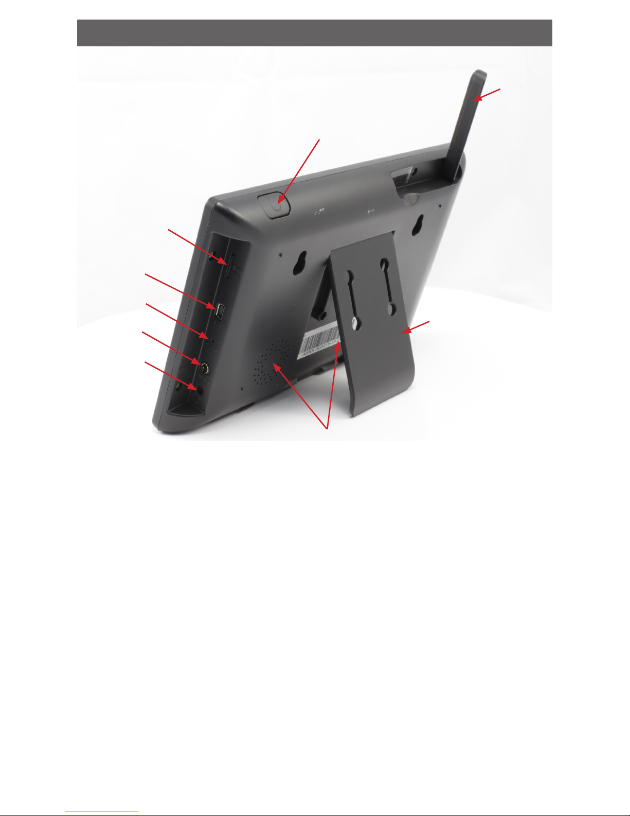
Layout: Side/Rear of the Receiver
Power button: When o, press and hold for three seconds to turn on. To turn the Receiver o,
press and hold for three seconds (note that while the Receiver is o, no recording is possible).
Power Socket: For connecting the included 5V power adapter.
MicroSD Card Slot: Insert a standard MicroSD card (up to 32GB) into this slot to store footage.
USB Port: The USB port is for production programming and does not have any function.
Antenna: The antenna can be folded down into the back of the screen (and this is how it will
be when you get it), ip it up to get the best signal.
Stand: If you want to put the receiver on a table, shelf or other at surface but have it at a
useful angle, the ip out stand on the back has you covered.
Speakers: The built-in stereo speakers are located on the rear. They’re louder than their size
may indicate (in this picture one speaker is hidden behind the stand).
A/V Out: If the LCD isn’t enough for your needs, you can connect the A/V cable to the video
inputs on a television or other display device. A/V inputs are often marked as such, and sometimes called Video In, Composite Video, AUX, CH0 or similar.
Reset Button: Using a small pin or similar, press here to reset all settings to factory default.
Antenna
Stand
Power Button
Micro SD Card Slot
Reset Button
A/V Out
Power Socket
Speakers
USB Port
6
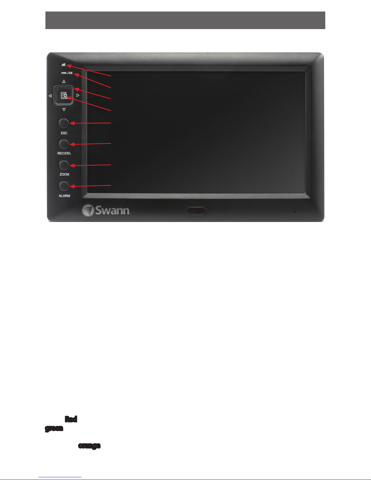
Screen: The wireless receiver features a built-in LCD screen which is able to display all four
channels at once.
Buttons: For accessing and controlling the built-in menu system.
• Arrow buttons: For navigating through the menu system and highlighting options. In
live viewing mode, the Up/Down Arrows select a channel and screen mode (single or
quad), while the Left/Right Arrows act as volume control.
• Menu Button: From the live-view screen Menu opens the menu system, in the System
Menu it is used for conrming choices. Note: You can only access the menu when
recording is not in progress.
• ESC: The escape button exits a menu or sub-menu.
• REC/DEL: In live-viewing mode, this is the manual record button. It will initiate recording
if the receiver is not currently recording, and stop a recording in progress if it is. If pressed
while in the playback interface or navigating the le list, it acts as the delete button.
• ZOOM: Increases the zoom on the image to 200% from standard view, or returns to the
standard view if pressed while zoomed.
• ALARM: Toggles the alarm buzzer on and o.
Signal/Pairing LED: While lit, this indicates that the receiver is able to receive images from at
least one of the paired cameras. This LED will ash when the receiver is in pairing mode.
Power Indicator: Indicates whether the unit is on or o, and shows what power source it’s
using. Red indicates the unit is running o its internal battery or the battery is fully charged,
green indicates that it’s connected to external power and the battery is charging. While
the battery is charging from an external power source, both LEDs will glow, which appears
somewhat orange.
Layout: Front of the Receiver
Power Indicator
Arrow buttons
Menu button
ESC
REC/DEL
ZOOM
ALARM
Signal/Pairing LED
7
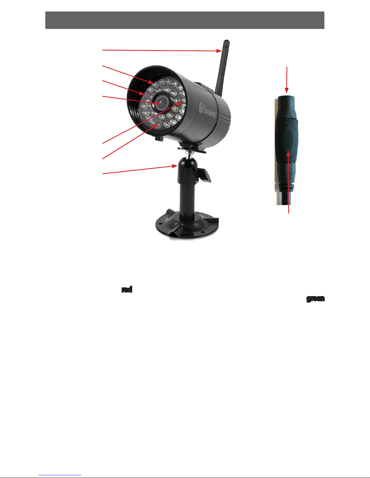
Layout: The Camera
Antenna: For best results, this should be fully extended, as high as possible and with as few
obstructions as possible between the camera and receiver.
IR LEDs: These powerful LEDs put out light that the human eye cannot see, but which the
image sensor in the camera can. It acts as a ood light at night so that the camera can see.
Power / Link LEDs: The red power LED will be lit whenever the camera is being supplied
enough power to operate (typically, whenever it’s connected to its power adapter). The green
link LED will be lit when the camera and receiver are able to properly communicate back and
forth.
Lens: The business end of the camera - where light enters the barrel and is focused on the
image sensor.
Light Sensor: Detects light levels and turns the LEDs on and o automatically
Stand: The camera should be rmly mounted to a wall, ideally about 10’ (3m) o the ground.
At this height, it’s low enough to see detail where needed, but high enough to be out of harm’s
way. See the “Mounting Guide” on page 21 for more information on mounting the camera.
Power Socket: For connecting the included 5V power supply, push the plug in rmly to engage the rubber seal. This connection is water resistant: if you have to mount the camera
somewhere exposed to the elements, then this connection should be protected from the
weather. We suggest a generous coating of a silicone-based sealant or waterproof tape.
Pairing Button: The pairing button is located on the end of the power cable of the camera
shielded from the weather by a silicone rubber layer.
IR LEDs
Light Sensor
Stand
Power LED
Lens
Link LED
Antenna
Power socket
Pairing Button

8
Setup Guide
All you’ll need is a couple of power outlets and somewhere to set everything up so you can get
it all connected. Don’t worry about xing anything to the wall yet, that comes later.
1. Plug the Receiver unit into power using the included 5V power supply.
2. Connect your camera(s) to power using their 5V power supplies. For easy setup, set them
up within arm’s reach of the receiver – you can move them to their nal locations soon.
3. Press and hold the power button for about three seconds to turn on the receiver. It will
take a moment to start up.
4. The included camera(s) should automatically be paired with the receiver. Wait a few seconds for images to appear on the screen.
5. If you don’t see any images from your camera(s), the camera(s) may need to be manually
paired - see “Menu: Camera Setup” on page 12.
6. Once paired you can move the camera(s) to its/their intended location(s) (they will stay
paired even if turned o and on again).
7. Setup the receiver in a location that best suits your recording needs and place your cameras in their intended locations.
Suggested Receiver setup procedure:
1. Set the Date and Time: We recommend you start here and make sure everything looks
right. If you want to use the video as evidence of a crime it is crucial that the time and date
are set correctly (see “Menu: System Setup” on page 9).
2. Prepare your MicroSD card as the storage medium. For the longest ongoing operation
use a 32GB MicroSD card with Overwrite enabled (see “Menu: Miscellaneous (continued)” on page 19).
3. Choose a recording mode. We suggest using Motion-based recording where possible,
as this will allow the receiver to work autonomously for the longest period of time possible. Use Schedule-based recording where necessary. See “Menu: Record Setup” on page
13.
That’s it - you should be up and running! From here, you can:
• Read through the Menu section (page 9 - page 19) of the manual for a rundown of
what dierent options do. Setting the motion sensitivity just right can make a big dierence, for example.
• Retrieve and playback footage: check out “Menu: Event List/Playback” on page 17.
• If you’re having problems or things just don’t seem to be working out, have a look at:
- “Tips & Tricks: Getting the most out of your ADW-340” on page 22 and
- “Troubleshooting: Cameras & Receiver” on page 23.
See the following pages for more detailed information on how each individual feature can be
set to suit your needs.
 Loading...