

Page 1

— 1 —
Directory
I. DVR Features ......................................................................................................... 2
II. Layout....................................................................................................................2
2.1 Front Panel............................................................................................................................2
2.2 Rear Panel............................................................................................................................3
2.3 Remote Control.....................................................................................................................3
III. DVR Installation.......................................................................................................4
3.1 Install Hard Disk....................................................................................................................4
3.2 Connect Camera and Monitor ...............................................................................................5
3.3 Connect Power Cord.............................................................................................................5
IV. DVR System Boot ..................................................................................................5
4.1 Detect Installed Hard Disk.....................................................................................................5
4.2 Recover Lost Data.................................................................................................................6
4.3 Restore Recording Process ..................................................................................................6
4.4 Main Screen.......................................................................................................................... 7
V. DVR Setup ..............................................................................................................7
5.1 Setup Menu...........................................................................................................................7
5.2 Camera Select.......................................................................................................................8
5.3 Record Select........................................................................................................................9
5.4 Record Mode.........................................................................................................................9
5.5 Record Frame Rate.............................................................................................................10
5.6 Record Quality.....................................................................................................................10
5.7 Record Schedule.................................................................................................................10
5.8 Auto Record………………..………………………………………………………………………11
5.9 Sub Menu-Password Setup……………..………………………………………………………11
5.10 Sub Menu-Password Change.............................................................................................11
5.11 Sub Menu-Picture Setup.....................................................................................................12
5.12 Sub Menu-Time Setup........................................................................................................12
5.13 Sub Menu-PTZ Setup.........................................................................................................13
5.14 Hard Drive Setup ................................................................................................................13
5.15 Alarm Setup........................................................................................................................14
5.16 NTSC/PAL Output Select....................................................................................................17
5.17 Restore Factory Default......................................................................................................17
VI. Record...................................................................................................................18
6.1 Start Recording.....................................................................................................................18
6.2 Stop Recording.....................................................................................................................19
6.3 Recording Length..................................................................................................................19
VII. Playback............................................................................................................... 20
VIII USB Programming...............................................................................................21
8.1 Install ....................................................................................................................................21
8.2 Program Interface.................................................................................................................21
IX. Specification..........................................................................................................26
X. Appendix...............................................................................................................27
10.1 System Connect Sketch Map..............................................................................................27
10.2 DVR Contents.....................................................................................................................27
Page 2
— 2 —
I DVR Features
z 4 Channel BNC Camera Input
z 2 Channel BNC Monitor/VCR Output
z NTSC / PAL
z Video Loss Alarm
z Motion Detection With Area Setting
z PTZ Control With RS-485 Port.
z Connect to PC With USB 2.0 Port, for Playback
z 4 Sets NO/NC Sensor Input
z 1 Alarm Output (2A 28VDC / 2A 125 VAC)
z One ATA-100 Hard Disk Interface, Support Over 200G Byte
z Time Schedule record / Sensor Triggered Record / Motion
Triggered Record
z IR Remote Controller
z
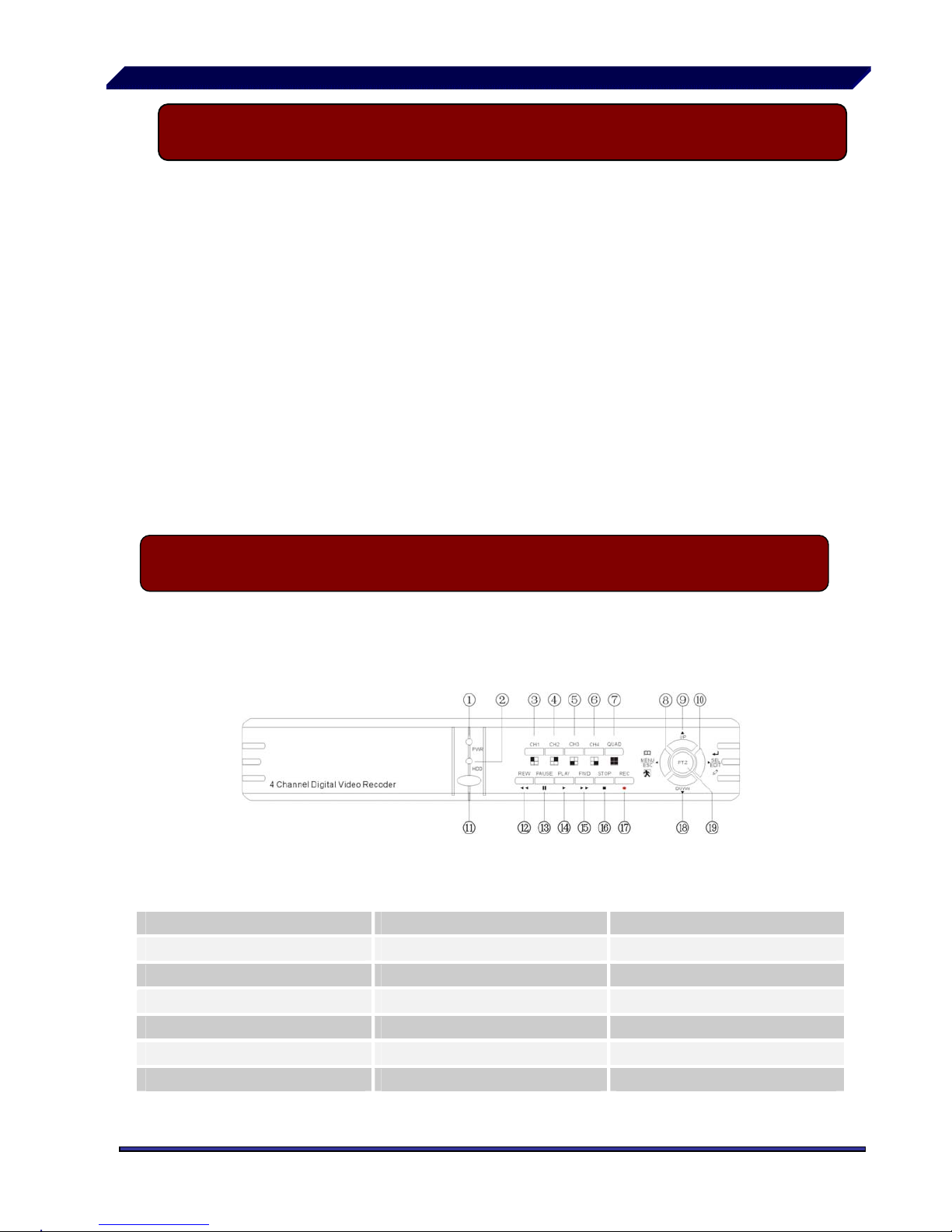
II Layout 2.1 Front Panel
1 Power LED 8 Menu /Exit 15 Forward
2 HDD Access Indicator 9 Move Up 16 Stop
3 Channel 1 10 Select /Edit 17 Record
4 Channel 2 11 IR Window 18 Move Down
5 Channel 3 12 Rewind 19 PTZ Switch
6 Channel 4 13 Pause
7 Quad View 14 Play
Page 3

— 3 —
1. USB Port 2. Video Output
3. Video Input 4. RS-485/Sensor /Alarm
5. DC Input 6. Power Switch
7. Fan 8. Grounding
1.CH1 Select or enlarge CH1
2.CH2 Select or enlarge CH2
3.CH3 Select or enlarge CH3
4.CH4 Select or enlarge CH4
5.QUAD Quad View
6.REW Rewind or Zoom-
7.PLAY Play record list or Focus+
8.FWD Forward or Zoom+
9.RECORD Record
10.PAUSE Pause or Focus-
11.STOP Stop recording or playing
12. PTZ PTZ Switch
13.MENU Enter or exit setup menu or Move
DOME left
14. UP Move up prompt or Move DOME up
15. Sel/Edit Modify item or Move DOME right
16.DOWN Move down prompt or Move DOME
down
II Layout 2.3 Remote Control
II Layout 2.2 Rear Panel
Page 4

— 4 —
III DVR Installation 3.1 Installing Hard drive
1. Remove the screws around the top cover.
2. Remove the top cover carefully.
3. Connect the power cord and data cable to hard disk carefully.
Ensure the HDD is set to MASTER.
4. Use the provided screws to fix hard disk on the rack.
5. Then replace the cover the case and fix it to the case.
CAUTION:
Do not open the cover when DVR is running!
Make sure the HDD is set to MASTER.
Page 5
— 5 —
III DVR Installation 3.2 Connect Camera and Monitor
There are 4 camera inputs and 2 monitor outputs with BNC connectors.
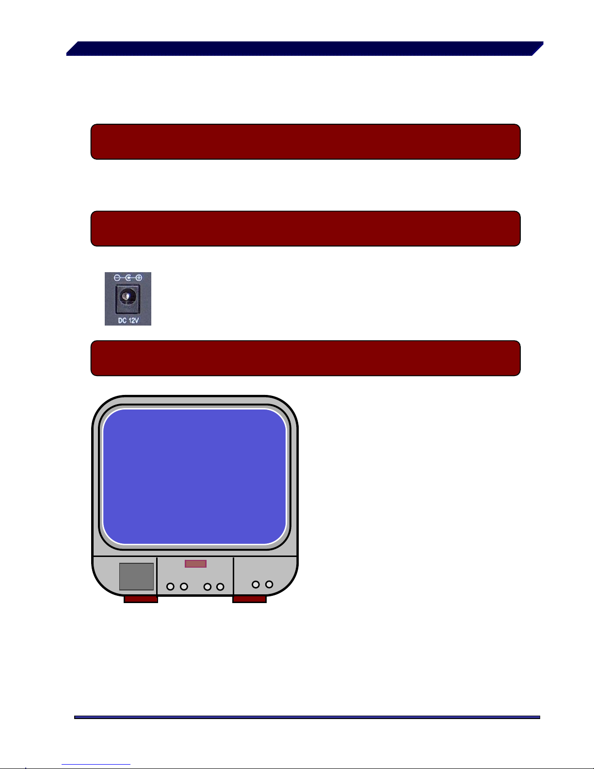
III DVR Installation 3.3 Connect Power Cord
Please use the power adapter supplied with DVR.
IV DVR System Boot 4.1 Detect Installed Hard Disk
HDD Checking………..
After connecting the power, system
will boot-up and detect installed hard
disk. On the Monitor it will show
hard-disk information.
Please make reference to hard disk
manual to configure hard disk drive
to Master.
Page 6

— 6 —
IV DVR System Boot 4.2 Recover Lost Data
A Power-Error can cause data
to be lost and the system will
ask to ‘Recover HDD’ at the
next start up.
Please press “
Select” to
proceed.
IV DVR System Boot 4.3 Restore Recording Process
RECOVER HDD?
04811-101735
(SELECT) YES/(MENU)NO
POWER ERROR DETECTED
RESTORE HARD DISK (MASTER) OK
RESTORE REC MODE…………… OK
re-connected.
When power-error happens
during recording process, the
system will automatically resume
recording after power is
Page 7
— 7 —
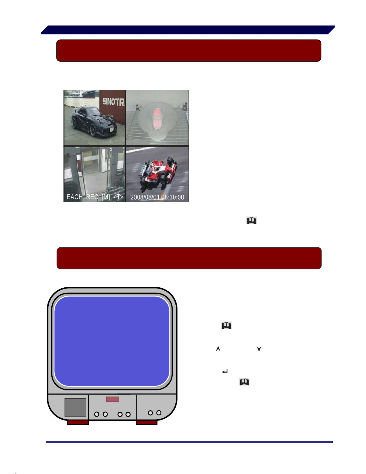
IV DVR System Boot 4.4 Main Screen
V DVR Setup 5.1 Setup Menu
With the DVR running, the
monitor will show the view f
rom the cameras.
Upper left Æ percentage of
hard disk space used.
Middle Æ channel name (C
H1 CH4).
Bottom right Æ date and
time shown.
1. Bottom left Æ Mode,
Status, HD Info, Schedule mode of DVR. Refer to
6.1
Start Recording
Eg. DVR is in record mode,
waiting for stop key press.
Then press “
30%
Menu” on
DVR to enter setup process.
MAIN MENU
C
AMERA SELECT 1234
RECORD SELECT 1234
RECORD MODE EACH
RECORD FRAMERATE 25
VIDEO QUALITY NORMAL
RECORD SCHEDULE
SUB MENU
HARD DISK SETUP
ALARM SETUP
RESTORE FACTORY DEFAULT
PRESSUPDOWN. THEN(SELECT)
PRESS(MENU) TO EXIT
Press “ Menu” to enter setup
menu,
Use “
Up” and “ Down” to
select item,
Press “
Select” to modify
settings and “
Menu” to exit.
Page 8
— 8 —
Menu Directory
Camera Select
Main Menu
Record Select
Record Mode
Record Frame Rate
Video Quality
Record Schedule
Sub Menu
Hard Drive Setup
PTZ Setup
Auto Record
Password Setup
Password Change
Picture Setup
Time Setup
Alarm Setup
Restore Factory Default
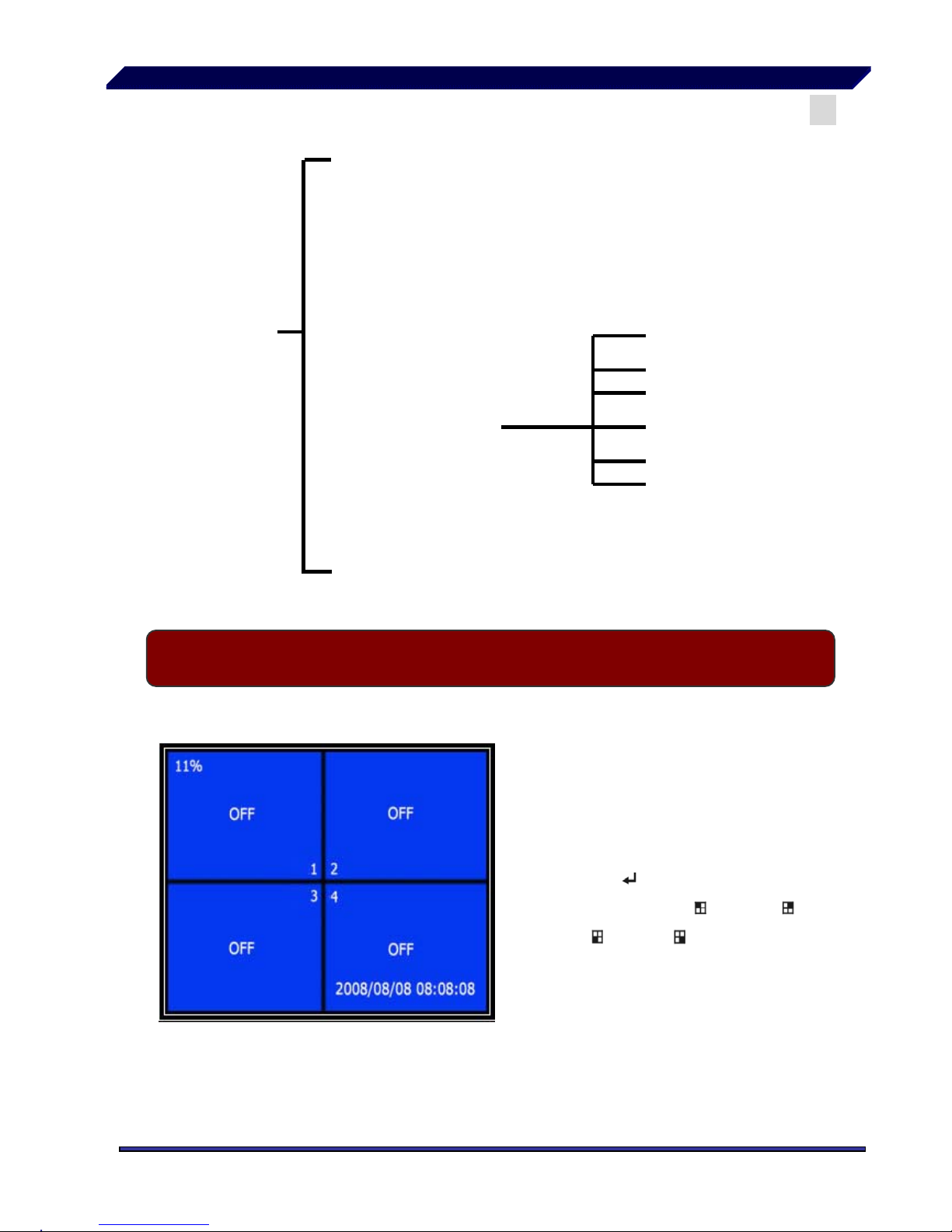
V DVR Setup 5.2 Camera Select
The DVR system can
display 4 cameras and video in
one picture (Quad Mode).
Users can configure which
camera is allowed to display.
Press “
Select” to modify
setting and press “
CH1”, “
CH2”, “
CH3”,“ CH4” to set
each channel separately.
If the channel is disabled,
the system will display “OFF”
on monitor.
Page 9

— 9 —
V DVR Setup 5.3 Record Select
eo.
Configure which channel is allowed to record.
V DVR Setup 5.4 Record Mode
There are two modes for video recording,
Each Mode The DVR will compress and record each video channel
separately therefore, the user can enlarge a single
channel to full screen display . For example, the user can
turn off the record function of CH-1 and CH-2 and then
the system will only record CH3 and CH4 vid
Press “
CH1”, “ CH2”, “ CH3”, “ CH4” to switch
between channels when playing back recorded video.
Loop FunctionWith system in play back mode or recording, press the
“QUAD” button and hold for three (3) seconds to make each video channel
enlarge to full screen.
The full screen will be displayed for five (5) seconds.
The loop will continue until any button is pushed.
ngle
Quad ModeThe DVR will compress and record all 4 video channels
into one file, therefore the user cannot enlarge a si
channel to full screen in play back mode. User can’t use
the video loop function in this mode.
V DVR Setup 5.5 Record Frame Rate
Page 10

— 10 —
Record frame rate
will affect the movement of object in recorded video.
More frames per second gives more smooth movement and uses more hard
disk space.
System default value is 25 fps for PAL (NTSC is 30fps), that means the
system will record 25 frames per second. User can set frame rate as for PAL
25,12,8,6,4,3,2,1 frames per second (NTSC is 30,15,10,7,5,4,3,2,1)
V DVR Setup 5.6 Record Quality
There are three level of record quality, High, Normal and Low.
Higher quality uses more hard disk space.
Record frame rate, record quality and hard disk space will affect total
record time of DVR system.
V DVR Setup 5.7 Record Schedule
User can setup video record method by time, Sensor Triggered or Motion
Triggered and Continuous Recording.
RECORD SCHEDULE
TTTAAATTTTTTAAAATTTTTTTT-
│ │ │ │ │ │ │ │ │
0 3 6 9 12 15 18 21 24
PRESSUPDOWN. THEN(SELECT)
PRESS(MENU) TO EXIT
Works with many kinds of external
sensor equipment like PIR, Gas sensor.
DVR will not record video until external
sensor is triggered and outputs signal to
notify DVR during this specified period of
time.
Button function:
Up Down:move the prompt
Select:Select Method.
“-” No Record
“T” Continuous, (System default)
“A” Sensor Triggered or Motion Triggered.
V DVR Setup 5.8 Sub Menu-Auto Record
Page 11

— 11 —
When you select “ON” DVR will be active to record automatically if
DVR has not been operated in five min
utes.
When you choose “OFF” DVR will not record until you press “RECORD”
button.
V DVR Setup 5.9 Sub Menu-Password Setup
When password set is “ON”, Stop recording or enter menu will need
Password. If password set is “OFF”, option is disabled.
V DVR Setup 5.10 Sub Menu-Password Change
System default password: Press “ CH1” button six times.
CURRENT PASSWORD :……
NEW PASSWORD :……
CONFIRM PASSWORD :……
User needs to enter six
characters for the
password.
All keys can be used as
password key except the
“
Menu” key, which is
used to exit.
Page 12

— 12 —
V DVR Setup 5.11 Sub Menu-Picture Setup
HUE: 0-99
SATURATION: 0-99
CONTRAST: 0-99
BRIGHTNESS: 0-99
Button functions:
Up Down:move the prompt
REW:Increase Value
FWD:Reduce Value
CH1-CH4,QUAD:Select Channel
Menu:exit.
V DVR Setup 5.12 Sub Menu-Time Setup
TIME SETUP
2006/01/18 08:30:00
PRESS(UP,DOWN), THEN(SELECT)
PRESS(MENU) TO EXIT
Configure DVR system time.
Press
Upand Downto
move prompt and press
Selectto modify. Press
Menuto save and exit.
V DVR Setup 5.13 Sub Menu-PTZ Setup
Page 13

— 13 —
PTZ SETUP
CHANNEL ADDRESS PROTOCOL BAUD R ATE
1 1 PELCO-D 2400
2 2 PELCO-D 2400
3 3 PELCO-D 2400
4 4 PELCO-D 2400
(<,>)MOVE (<<,>>)ADJUST (MENU)EXIT
CHANNEL: Camera Number
ADDRESS: Speed Dome’s address,
Can be changed from 0 to 255
PROTOCOL: Supports “PELCO-D”,
“PELCO-P”, “SAMSUNG”, “BO1”, “NEON”,
“CTNCOM”, Set the protocol according to
the Speed dome’s protocol.
BAUD RATE: Press “EDIT” button to select
the value. Can be changed from 1200bps to
19200bps, the default value is 2400bps
If user has compatible Speed Domes attached to DVR, press the “PTZ” button and
select the camera number that you wish to control. Now, user can use
“Up”, ”Down”, ”Right”, ”Left” buttons to control the Speed dome’s horizontal and vertical
position. Press “ REW”,”FWD”,”PAUSE” and “PLAY” buttons to control Speed Dome’s
ZOOM and FOCUS functions.
Notice: Make sure that all the lines are connected to the Speed Domes correctly, and
the protocol, baud rate and address parameters are set correctly also.
V DVR Setup 5.14 Hard Drive Setup
/
HARD DISK SETUP
OVERWRITE ENABLED [YES]
MASTER HDD SIZE 120042MB
MASTER HDD USED 80865MB 77%
MASTER HDD FORMAT
SLAVE HDD SIZE N/A
SLAVE HDD USED N/A
SLAVE HDD FORMAT
PRESS(UP,DOWN), THEN(SELECT)
PRESS(MENU) TO EXIT
OVERWRITE ENABLED:
If you choose YES, recording continues
and overwrites previous recording when hard
disk drive space is full.
If you choose NO, the recording process
stops when all hard disk drive is full for
recording.
MASTER HDD SIZE:
It shows the size of the master hard disk
drive installed in the DVR.
MASTER HDD USED:
Page 14

— 14 —
It shows the space used on the master hard disk drive for recording and the percent of
the used hard disk.
MASTER HDD FORMAT:
If you format the hard drive, it will erase all the data recorded on the master hard disk
drive.
Notice: when you first use a HDD in the DVR, please use this function to format the
HDD. Otherwise the computer will not find the HDD when you connect the DVR to the
computer by using the USB cable.
SLAVE HDD N/A
V DVR Setup 5.15 Alarm Setup
ALARM RECORD DURATION
The number indicates how long
triggered recording lasts after the
sensors are triggered or the
movements in front of the camera.
ALARM DURATION
It controls how long (in seconds)
the alarm lasts after the system is
triggered.
ALARM SETUP
ALARM RECORD DURATION 5
ALARM DURATION OFF
BUZZER DURATION OFF
SENSOR SETUP
MOTION SETUP
BUZZER DURATION
Buzzer time set (OFF,05,10,15,20,25,30 seconds and CONT) , User
can press [
Select ] to set the time .When Buzzer Time is “OFF”,
the buzzer will be shut off. When “Buzzer T ime” is “CONT”, the buzzer
will work continuously.
Page 15

— 15 —
Sensor Setup
There are 3 different modes for sensor setting:
NOT INSTALLED, NORMAL-CLOSE and
NORMAL-OPEN.
It depends on what type of external sensor
you are using. If sensor’s output is
NORMAL-OPEN then select NORMAL-OPEN
mode in DVR.
SENSOR SETUP
CHANNEL-1 TYPE:NORMAL-OPEN
CHANNEL-2 TYPE:NORMAL-CLOSE
CHANNEL-3 NOT INSTALLED
CHANNEL-4 NOT INSTALLED
PRESSUPDOWN. THEN(SELECT)
PRESS(MENU) TO EXIT
If the sensor connected to the DVR is triggered by an intruder, then the
DVR will automatically start recording process.
Note: the recording method is set to alarm recording in the first place.
Sensor Input 1 2 3 4
PTZ
Alarm Out
Push the UNLOCK BUTTON to insert and pull out the wire
Install example diagram:
Page 16

— 16 —
Motion Setup
1. User setup video record method by Motion Trigger. Reference 5.7.
MOTION DETECTION SETUP
CHANNEL 1 SENSITIVITY 4
CHANNEL 2 SENSITIVITY 4
CHANNEL 3 SENSITIVITY 4
CHANNEL 4 SENSITIVITY 4
CHANNEL 1 AREA SET
CHANNEL 1 AREA SET
CHANNEL 1 AREA SET
CHANNEL 1 AREA SET
PRESS(UP,DOWN), THEN(SELECT)
PRESS
(
MENU) TO EXIT
CHANNEL 1- 4 SENSITIVITY:
Press “
Select” to adjust
sensitivity of motion detection.
High (1----------9,OFF) Low
When it’s OFF, the channel cannot
be triggered by movement.
CHANNEL 1- 4 AREA SET:
Press “
Select” to enter area
setting state, the picture of selected
channel is divided into 144(12*12)
blocks, and then press “REW” to
move left, press “FWD” to
move right, press “UP” to move up, press “DOWN” to move down, press “
Select” to set the block to being active or not.
When the block is transparent, it’s active to record.
When the block is covered by shadow, it is not active. NO Recording.
After completing the “MOTION SET”, User can exit MENU, And press
[ Record ] to start Motion Record.
V DVR Setup 5.16 NTSC/PAL Output Select
Page 17

— 17 —
Change jumper J10 to select NTSC or PAL video output format according to
the silkscreen on the PCB.
NTSC/PAL Select
V DVR Setup 5.17 Restore Factory Default
ALL SETTING DATA IS INITIALIZED
If user selects this item, the
system will restore all user’s
settings to factory default values,
and DVR will reboot.
VI Record 6.1 Start Recording
Page 18

— 18 —
Press “ Record” to start recording according to the record schedule
that user has set. System will display some information on Screen.
Only EACH MODE can enlarge single channel to full screen display
QUAD REC [M] (T) 2008/07/01 16:22:30
10%
R
R
R
R
1
3
2
4
5
6
7
8
1. Hard Disk Usage (Displayed as a percentage)
2. Recording Symbol
3. Channel Name
4. Mode (QUAD or EACH)
5. Status (REC, Play, FF1, FF2, FF3, REW, PAUSE)
6. HD Info. ([M] Master disk [S] Slave disk)
7. Schedule (T) Continuous (A) Sensor or Motion () No Record
8. The time and date of the DVR
VI Record 6.2 Stop Recording
Page 19

— 19 —
Press “ Stop” and system will prompt you to input password. Only
correct password can stop recording process. This is with Password option
enabled. With Password option disabled, Press “
Stop” will stop recording.
Estimated record time based on 80G Byte HD (Quad Mode) Unit: Hours
Format Quality Frame Rate
30 15 7 1
HIGH 20 38 78 167 1165
User can calculate and estimate record hours by below formula
80G Byte @ 7 frames per second @ Normal quality
80 (G byte) x 1024 (M byte) x 1024 (K byte)
in)
15 (Kbyte/frame) x 7 (frame/sec) x 60 (sec) x 60 (m
Estimate hours is 222 Hours
NORMAL 15 52 103 222 1533
NTSC
LOW 12 64 129 277 1942
Format Quality Frame Rate 25 12 6 1
HIGH 20 46 97 194 1165
NORMAL 15 62 129 258 1553
PAL
LOW 12 78 162 323 1942
VI Record 6.3 Recording Length
VII Playback 7.1 Play
Page 20

— 20 —
Press “
Play” ,then system will list all recorded video clip from HD.
Newest video will be at top of the list, press “
Move Up” and “ Move
Down” to select start time and press “
Play” again to start play video to
the end.
1.Hard Disk usage 4. End Time
2. HD Information (Master or Slave) 5. TIME: Continue record
3. Start Time
6. ALARM: Sensor or Motion Triggered
Another way to search video is directly input time period. Press “
Forward” and then press “
Up” and “ Down” to move prompt. Press
“
Select” to edit time value and press “ Play” to play video.
VIII USB Programming 8.1 Installation
2008 /0 1 / 0 8 08 : 30 : 3 2 --- 2008/0 1 / 0 8 16 : 00 : 05
2008/01/08 16:00:35
2008/01/08 15:50:20
2008/01/08 14:30:56
2008/01/08 14:15:30
2008/01/08 14:00:15
2008/01/08 13:55:37
2008/01/08 11:30:12
2008/01/08 10:15:30
2008/01/08 08:30:55
MOVESELECTCHANGE PLAYPLAY
MENUEXIT SELECT EVENT OR TIME
4
*
SEARCH TIME
2008/01/08 08:30:56
01 TIME
02 TIME
03 TIME
04 TIME
05 ALARM
06 ALARM
07 ALARM
08 ALARM
/
50%
1
3
5
6
5
HARD DRIVE:
2
Page 21

— 21 —
1. Put the USB Driver Program CD in your CD-ROM Drive.
2. Open CD directory.
3. Double click on “Set up”.
4. Run “Install” program.
VIII USB Programming 8.2 Program Interface
Run the program (Double click “ ” icon on desktop)
System will detect the HDD automatically when user connects the USB cable
to PC.
*Notice: if the HDD can’t be detected because of fault, please
restart according to the following steps:
(1) close the USB program window, and remove the USB cable
(2) press [ Play ], then connect the USB cable to PC, and try again
Page 22

— 22 —
1 Save Frame 2 Save Video Clip
3 Config 4 Printer
Button functions
Page 23

— 23 —
5 Event List 6 Channel 2
7 Channel 1 8 Quad Mode
9 Channel 3 10 Channel 4
11 Fast backward 12 Back one frame
13 Backward play 14 Pause
15 Play 16 Next one frame
17 Fast forward 18 Playing Scroll Bar
19 Play DVR video file 20 Play PC video file
21 Minimize the window 22 Close the window
23 Volume Scroll Bar
Press to open the event video list.
Press to configue the DVR play/record system.
Page 24

— 24 —
Press to print the picture of DVR’s playback
Page 25

— 25 —
Press to play the video .
IX Specifications
Page 26

— 26 —
ITEM DESCRIPTION NOTE
Video Format NTSC / PAL
Operation System None STAND-ALONE
Camera Input Channel 4 channel Composite BNC
Video Output Channel
2 channel Composite BNC
USB 2.0 Port
NTSC 120 frames/second 4 x 30 frames/second
Display Frame Rate
PAL 100 frames /second 4 x 25 frames/second
NTSC Max 30 fps (Quad) Quad Mode Recording Frame Rate
(Quad)
PAL Max.25 fps (Quad) Quad Mode
NTSC
Each Channel =
30fps ÷ Number of Source
Max. 30 frames/s
(Each Channel)
Recording Frame Rate
(Each Mode)
PAL
Each Channel =
25 fps ÷ Number of Source
Max. 25 frames/s
(Each Channel)
Record Mode
Continuous, Schedule, Motion
Triggered, Sensor Triggered
Display
NTSC720 x 480
PAL720 x 576
Resolution
Record
NTSC320 x 112, 640 x 224
PAL320 x 136, 640 x 272
Quad640 x 224 (total)
Each640 x 224
Video Compression Format
(Each Channel)
Modified Motion-JPEG
(12-20K bytes/frame)
Low: 12K Byte
Normal: 15K Byte
High: 20K Byte
HDD Support Over 200G Byte ATA -100 Interface
Estimated Record Length
80G Hard disk @ 7 fame per second @ Normal Quality
(80*1024*1024 K byte) ÷ ( 7*15*60*60 ) = 222 Hours
Method TimeDateEvent
Search
Full Screen YES
Sensor, Alarm
4 Input (Normal Open / Normal Close)
1 Input (Relay 2A 28VDC / 2A 125VAC)
Camera Signal Loss Alarm
PTZ YES
USB YES USB2.0 Port for playback
Dimension (H x W x D) 2.04 * 8.81 * 12.40 / 52 * 224 * 315
Page 27

— 27 —
X Appendix 10.1 System Connection Map
X Appendix 10.2 DVR Contents
 Loading...