

Page 1
Hardware Quick Start Guide
QH48_1590150716E | © Swann 2016
Welcome! Lets get started.
To start using your DVR, you need the following:
1. A high-definition TV capable of displaying 720p or
1080p video. Look at the ports on the back or side of
your TV to make sure it has an HDMI input.
2. A router with a broadband internet connection.
3. A mobile device (Android or iOS) to download the
free HomeSafe View app.
Carefully unpack each item and discard any packaging not required.
Security Made Smarter
Page 2
Congratulations on the purchase of your Swann DVR. This Quick Start Guide will assist you on getting your DVR up and
running as soon as possible. To make sure nothing was damaged during shipping, we recommend that you connect
everything and give it a try before you do a permanent installation.
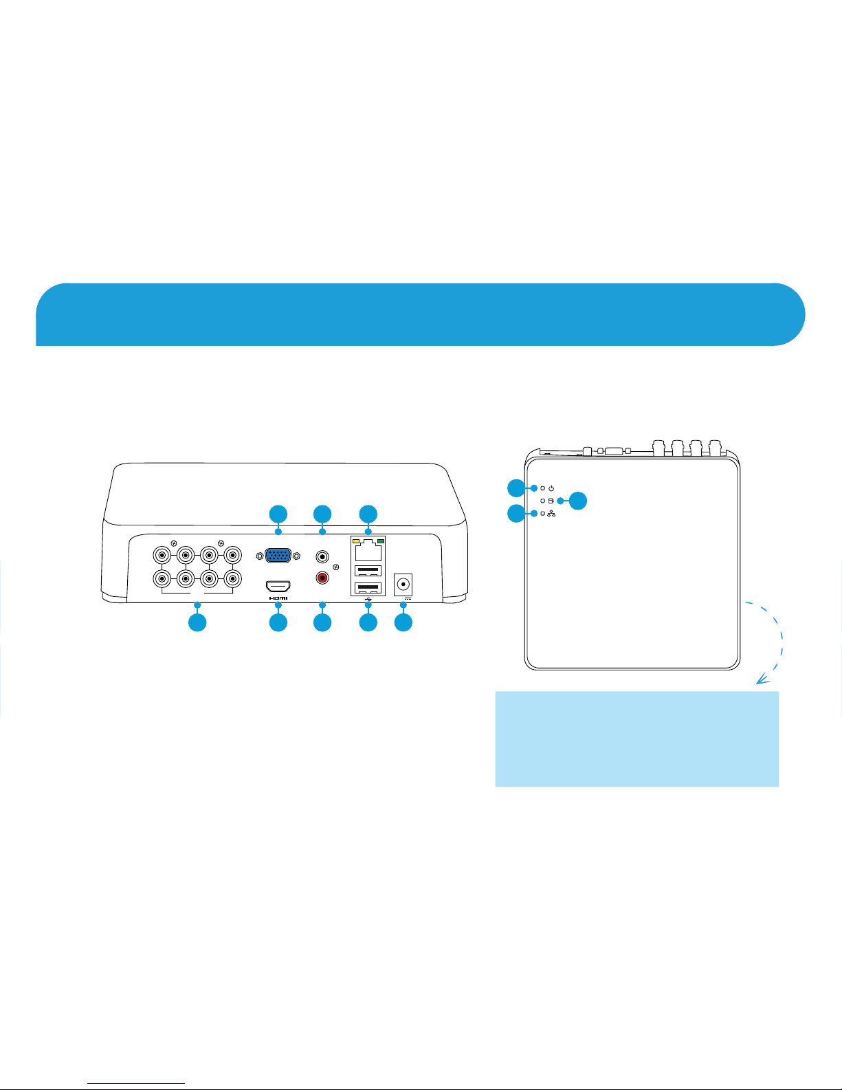
Your DVR is designed to ventilate air
to keep it at an optimal temperature.
Keep both sides of your DVR free from
obstructions to allow it to ventilate.
Getting to know your DVR
9
11
10
1 3 5 7
2 4 6 8
VIDEO
INPUT
VIDEO
INPUT
VGAVGA
AUDIO
INPUT
AUDIO
INPUT
AUDIO
OUTPUT
AUDIO
OUTPUT
12V12V
LANLAN
3 5
7 8
2 4 6
1
1. Camera Inputs
2. VGA Port
3. HDMI Port
4. Audio Input
5. Audio Output
6. Ethernet Port
7. USB Ports
8. Power Port
9. Power LED
10. Hard Drive LED
11. Network LED
Page 3
1. Camera Inputs: Connect your cameras here. Twist the
video connection to lock it in place.
2. VGA Port: Connect this to your monitor with a VGA input.
This is not required when using the HDMI port.
3. HDMI Port: Connect this to your TV with a HDMI input
(HDMI cable supplied).
4. Audio Input: For connecting a microphone (the
microphone must have its own power source).
5. Audio Output: For connecting to a stereo or amplifier.
This is not required when using the HDMI port.
6. Ethernet Port: Connect this to your router so your DVR
can connect to the internet.
7. USB Ports: Connect the mouse here. You can also
connect a storage device such as a USB flash drive to copy
recorded events or to perform a firmware upgrade.
8. Power Port: Connect the DC 12V power adapter here.
9. Power LED: Indicates your DVR has power.
10. Hard Drive LED: Flashes when the hard drive is active.
11. Network LED: Flashes when there is network activity.
As your DVR is designed to be always on, there is no
power button. To turn off your DVR, use the Shutdown
function then disconnect the power adapter.
What does this mean?
FCC Warning Statement
This device complies with part 15 of the FCC Rules.
Operation is subject to the following two conditions:
(1) This device may not cause harmful interference
(2) This device must accept any interference received,
including interference that may cause undesired
operation.
Battery Safety Information
This product contains a coin/button cell battery. If the
cell battery is swallowed, it can cause severe internal
burns and can lead to death. Keep away from babies
and small children at all times.
• If the battery is swallowed, immediately seek
medical help
• Risk of explosion if replaced by an incorrect type
• Dispose of used battery properly
Page 4

1. Connect the video output and
power input connections on the
bullet camera to the corresponding
connections on the supplied video &
power cable.
2. Connect the power splitter to the
other end of the video & power cable.
This provides power to multiple
cameras using a single power
adapter.
3. Connect the other end of the
power splitter to the power adapter
then connect the power adapter to a
spare power outlet.
4. Connect the video output on
the video & power cable to each
camera input on your DVR. Twist the
connection to lock it in place.
The bullet camera has three points
of articulation, scroll down to the
last page for more information.
Step One: Connect your Cameras
Your DVR may include dome cameras instead of or in addition to the
bullet camera. Scroll down to the last page for mounting instructions.
2 3
Power Input
Video Output
1
Twist to lock
connectors
Video Input
Video & Power Cable
Connect this to your DVR
Power Splitter
connects here
Power Output
Power Adapter
connects here
Power Splitter
Power Adapter
Video & Power Cable
connects here
Connect to a spare
power outlet
4
Bullet Camera
1 3 5 7
2 4 6 8
VIDEO
INPUT
VIDEO
INPUT
VGAVGA
AUDIO
INPUT
AUDIO
INPUT
AUDIO
OUTPUT
AUDIO
OUTPUT
12V12V
LANLAN
Page 5

Connect the supplied Ethernet cable to the Ethernet port (1) on your DVR then connect the other end to a spare port (2)
on your router. Don’t proceed to the next step until this is done.
Please note: It’s important that you do this as this allows your DVR to send email alerts, synchronise its internal
clock and for remote access using the HomeSafe View app.
Step Two: Connect to your Home Network
1 3 5 7
2 4 6 8
VIDEO
INPUT
VIDEO
INPUT
VGAVGA
AUDIO
INPUT
AUDIO
INPUT
AUDIO
OUTPUT
AUDIO
OUTPUT
12V12V
LANLAN
1
USB
Interne t
4
3
2
2
Page 6

Connect the supplied mouse (1) to the bottom USB port (2). To copy your video recordings and to perform a firmware
upgrade, connect a storage device such as a USB flash drive (not included) to the top port.
Step Three: Connect your Mouse
1 3 5 7
2 4 6 8
VIDEO
INPUT
VIDEO
INPUT
VGAVGA
AUDIO
INPUT
AUDIO
INPUT
AUDIO
OUTPUT
AUDIO
OUTPUT
12V12V
LANLAN
Please note: Bluetooth and wireless mice and trackpad devices are not supported. Not all USB storage devices
are supported.
1
2
Page 7

Connect the supplied HDMI cable to the HDMI port (1) on your DVR then connect the other end to a spare HDMI input
(2) on your TV. The labels on your TV (back or side) indicate which input you need to select when your DVR is turned on.
HDMI IN 1
HDMI IN 2
Press the A/V button on
your TV’s remote to select
the HDMI input.
HDMI Cable
Step Four: Connect to your TV
2
1 3 5 7
2 4 6 8
VIDEO
INPUT
VIDEO
INPUT
VGAVGA
AUDIO
INPUT
AUDIO
INPUT
AUDIO
OUTPUT
AUDIO
OUTPUT
12V12V
LANLAN
1
Page 8

If you have a monitor with a VGA connection, connect a VGA cable (not supplied) to the VGA port (1) on your DVR then
connect the other end to the VGA input (2) on your monitor.
A VGA cable and monitor
are not required when
using the HDMI cable.
Step Five: Connect to your Monitor
1 3 5 7
2 4 6 8
VIDEO
INPUT
VIDEO
INPUT
VGAVGA
AUDIO
INPUT
AUDIO
INPUT
AUDIO
OUTPUT
AUDIO
OUTPUT
12V12V
LANLAN
1
2
Page 9

All connections have now been completed. You should see your DVR on the TV with the Startup Wizard displayed
on-screen. Follow the “Startup Wizard” Quick Start Guide (the red coloured guide) to configure your DVR.
Connect the supplied power adapter’s power connection (1) to the power input (2) on your DVR first (this will minimise
sparking). Connect the power adapter to a power outlet then press the outlet’s switch to the on position to supply power.
Step Six: Connect your Power Adapter
1 3 5 7
2 4 6 8
VIDEO
INPUT
VIDEO
INPUT
VGAVGA
AUDIO
INPUT
AUDIO
INPUT
AUDIO
OUTPUT
AUDIO
OUTPUT
12V12V
LANLAN
1
2
Page 10

Connect the video output on the video
& power cable to each camera input
(VIDEO INPUT) on your DVR. Twist the
connection to lock it in place.
Connect the supplied Ethernet cable
to the Ethernet port (LAN) on your
DVR then connect the other end to a
spare port on your router.
Connect the supplied mouse
to the bottom USB port.
To copy your video recordings and to
perform a firmware upgrade, connect
a storage device such as a USB flash
drive (not included) to the top port.
Your DVR is designed to ventilate air
to keep it at an optimal temperature.
Keep both sides of your DVR free from
obstructions to allow it to ventilate.
Connect the supplied HDMI cable
to the HDMI port on your DVR then
connect the other end to a spare HDMI
input on your TV.
Press the A/V button on your TV’s
remote to select the HDMI input your
DVR is connected to.
Connect the supplied power adapter’s
power connection to the power input
(12V IN) on your DVR first (this will
minimise sparking). Connect the
power adapter to a spare power outlet.
The bullet camera has three points of
articulation. Use the provided tool to
loosen each screw then adjust to the
desired position. Tighten each screw
again to secure in place.
Mounting and aiming the dome camera
1. Loosen the three screws located at
the base of the camera then remove the
bracket cover and dome cover.
2. Run the cable as required and using the
appropriate screws for the surface you are
mounting to, screw the bracket to fasten.
3. Replace the dome cover and bracket
cover. The camera can be aimed in
almost any direction. After you’ve finished
adjusting the camera’s viewing position,
tighten each screw to lock the position in
place.
Power Input
Video Output
Twist to lock
connectors
Video Input
Video & Power Cable
Connect this to your DVR
Power Splitter
connects here
Power Output
Power Adapter
connects here
Power Splitter
Power Adapter
Video & Power Cable
connects here
Connect to a spare
power outlet
Bullet Camera
3
1
2
USB
Internet
4
3
2
HDMI IN 1
HDMI IN 2
Power Adapter
1
2
4
3
5
HDMI Cable
Ethernet Cable
Dome Camera
1 3 5 7
2 4 6 8
VIDEO
INPUT
VIDEO
INPUT
VGAVGA
AUDIO
INPUT
AUDIO
INPUT
AUDIO
OUTPUT
AUDIO
OUTPUT
12V12V
LANLAN
1
4
2
3 5
Digital Video Recorder
Positioning the bullet camera
To avoid damage, don’t position
the camera without loosening the
screws and locking ring first.
This enables you to rotate the
camera left or right.
This enables you to position the
camera up or down.
Twist the locking screw counterclockwise to rotate the camera stand
left or right. Tighten the locking
screw clockwise to secure in place.
1
2
3
What are the additional connections for?
Audio Input: For connecting a microphone (the
microphone must have its own power source).
Audio Output: For connecting to a stereo or amplifier.
This is not required when using the HDMI port.
VGA Port: Connect this to your monitor with a VGA
input (VGA cable not supplied). This is not required
when using the HDMI port.
 Loading...