

Page 1

s,N.
7s35
OPERATION
S\^/AN
AND
MAINTENANCE
\.-
MODEL
TV.2C
6t.swAn
-/
305 Af4ort
Rord.
ELECTRONTCS
Cubic CotPoratlon
CA
ol
9rl05a
A subsidiarY
(rc.!ntldo,
'
P{tn
(714)
7gl'75i25
Page 2

GENERAL
DISCUSSION
Model
Swan
The
the
for
er
isoc,
is
it.uility
i.F.
I.F.
may
In
iransceiver
a
io
fius
ii..
Jitf.r"nce
received
Transceivei.
in-i"or
the
;;;d,
.i
crystal
350,
stindard
tlie
r.nge
ranles
be.qu'ite
standard
the
.144
mc.
1a.35
it'does
mc.,'the
Transce'iver
the
heterodyned
is
by
144
to
l+4
ana
frequency,
TV-ZC
2 meter
350C,-400;
intermedtite
frequency
and
in the'.|5
be ordered'through
may
easily
model
heierodyned
is
output
frequency
'144.35
as
when
from
Transceiver
the
is tunea
.|44.35
to
fir
being operated
iiiri..iu..-niii"fune
go
*ilr;-will
14.45
irn.t
up
A
to
'144.45
to
position
3
Convirston
Nffi;iiv,
i,i+.+S
io
iA+
"angei
requir...istal
.or"eiponiingly
mc.,
mc.
crystal
rangls.
tf,ii"trift
mc.,
respectivelY.
is a crystal
designed
band
5d0c,
500,
tr6quency,
readout.'Howlver,
m6ter,
modified
TV-2C
ifre
Transverter
frequency.
with dhe
of
from
mc. In
portion
mi.
tire
as
liO mc.,
higher
SO
'10
for
with
with
|V-ZC.
tg0 mc.
14 mc.
the
14 to
Transceiver
b€ added
than
the 2
rnetei
selector
Thus,
be tliree
144.45 to
three
adjacint
l4+.g
injection
controlled
operate
to
5oocx.
and
meter,
a
output
The
same
14.35
other
of
on
or
dealers'
Swan
a different
meter
20
.|30
mc. crystal
the
As
moves
receiving
in
crystal
difference
way
mL.,
words,
the 2
meier
is concerned,
rneters.
20
to
'14.35
higher.
range
switch
on
segnents
segments-at
mc.,
frequencies
transmitting
with
(I.F.),
the
meter
6
I.F.,
Transceiver
upward
aS-any.other
it
the
the
mc.,
For
when
the
of
swan
meter
20
The
since
TV-zc
amateur
when
or
range'
I.F.
14
the
controlled
in
mode,
iontrolled
witt'
band to
It
Transceiver
then
the
frequency,
oe
TV-2C
it tunes
is
the
instance,
using
'IU-ZC
the
provides
meter
2
the
ind'144.9
to
130,130.45,
of
receiving
and
Transceivers,
has been
band
it will
is also
bands.
mc
is tuned
frequency,
incoming
signal,
14 mc.
monitoring
Transverter
cover
only
dial
provide
available
required,
output
signal
from
alfays-.139
producing a.
or I.F.
signal.
14 to
the
operates
and
necessary
reading.
frequelc.y
Model
the
iniection
mc.
130
selection
for
band.may
end,
low
145.35
fof example:
mc.
and
convert-
Models
chosen
excellent
with
The various
TV-ZC
the
from the
produce
to
up
mc.
14
signal
signa'l
slgnals
simply
fllge-on
500C
at
'.is
As the
coming
converts
14.35
iust
that_the.
If^the
2
Transceiver
will
of
be covered.
These
130.9
three
mc.'
250'
its
.|44
Tg:
mc.
go
three
I.F.
.45
I.F.
meter
2
irom
on
KC
fiO
I.F.:
range
th6
"itt
across
mc.
will
range
UaiO
28
20
the
wiif
plus
MFTER
15
an
If
essentiatly
itrcqiieniv
Transceiver
alent
mc.
123
METER I.F.:
IO
an
If
in.
iun"i
350
if,rs,-if
iiO-'ic.
ina
6y-rii.di;g;
in the
t.r.
144
be
t"grenl
result
thui
in'the
will
29.7
to
meters.
Transverte"-t.F.
regutt
r..).
29lZ
met6r I.F.
l0
15 meter
with 20
as
minus
15 meter
the
of the
in a
l0
be tuned
mc.,0F
The Swan
in
an
Thirs,0lirger-p_ortion
2l
2
range
nBter
1700 KC
is on
operating
iange.
amateur
meter
mc.,
band,
meter
amateur
with
band
I.F.,
except
instead_gf
from
band.
of
2l
A
144 to
band
crystal
each
as compared
Transceivers
tune
l0 meters,
range
of-144
-In
?act,
preferre!,
is
that
.144
minus
21.45
to
crystal
144.45
iniection
mc,
is selected,
frequency,
450
to
l0
the
cryglal_iniection
a
by
.|45.7
to
the
of
proper
operation
the crystal
14 mc.
will
mc.
etc
wider-segment.of.
a
Th9
KC on
neter
mc.
rneter
2
selection
will
iniection
Tuning
tune
an
frequency
meter
l0
meters
15
in one range.
band
frequency
plus
(l16
band
can
the three
of
be
the.
equiv-
of
band
and
of
mc'
28
be
covered
rj
rf
Page 3

'..q'
crystal
covered.
as
does not cover the entire 4 mc. band width, but is
segments, the 20 meter I.F. range is
designated as standard.
METER
6
When the Swan 250 or
I.F.
entire
injection frequency wi'l'l be
ceiver
Since the
readout and
FREQUENCY
FREQUENCY MNGE:
TRANSMITTER
TMNSMITTER 0UTPUT
frequencies,
However,
good
range
with
as
I.F.:
will be in
2 meter band will be
from 50 to 54 mc.,
vernier dia'l
stability will
RANGE:
P0WER
overall stability and frequency
a 20 meter I.F.
0utput: 144-148 MC.
Input: 20 meter
RATING: 240
IMPEDANCE:
entire 2 meter band,
the
Since
250C
Transceiver is
the 6 meter band. The
covered with
144 minus 50 mc., or^ 94 mc. In tuning the
the
operating
on the Transceiver
good.
be
TECHNICAL
ona'l
opti
watts P.E.P. input with sing'le sideband voice
modulation, 180
Power
output
50 to 75
most
generally
freguency will tune from
SPECI
band
standard. 15,
.
in
ohm coaxial cable,
used
one crysta'l
covers
FICATIONS
from 144 to
operating in
recorrnended,
with the
advantage
watts CW
TUNE mode:
148 mc.
readout
concentrated
in
.5
mc.,
input,
80
will not be
the 2 meter
and
TV-2C Transverter,
in this case
the TV-2C.
(500
'10,
or 6 meter
75
100
to
series
be
may
band
in
small
has been
is
The crystal
.|44
to
freguency
KC),
bands
watts AM
+
watts.
tuned
quite
!
the
that the
Trans-
l4B
mc.
input.
link
TRANsMITTER
DIsToRTIoN
pR0Ducrs:oullllS;rrur.ry
RECEIVING CONVERTER: 3 RCA
MFIERING:
PANEL CONTROLS:
REAR PANEL
ruBE coMpLEMENT: 6JK6
TMNSISTORS:
'P0WER
DIMENSIONS: l3 in.
P.A.
Cathode
P.A.
Switch,
Current, 0-400 ma. Re1ative
Tune,
144
CONTR0LS AND CONNECT0RS: P.A.
rnjection o'o.f'lllli i;lffili''itl:l,t;:33'[:{,:l:"[[ilv
Power
8737
RCA
40673
2N706
REQUIREMENTS:
wide,
FET's
Crysta'l
(Normal'ly
both
the Swan Transceiver
Filaments,
Medium
High Voltage,
Voltage,
Bias
0sc.
Relay
Supply
Supply
5 I
30
40673
P.A.
mc.
Amp'lifier.
Osc.
Voltage,
/2
FET's
with Noise
Load, Driver Tune, Crystal
Transverter
0n-0ff.
Bias Adjust,
Relay
in
Rec. R.F.
2N706 Freq. Mul
,
supp'lied by
12.6
volts
275 volts
800 vo'lts
ll0
Voltage, l0
Voltage, 12
in. high,
Contro'l Jack, I.F. Output Jack,
CASCADE,
ti
Swan l17XC
and the
AC
volts
'll
in.
DC,
or
DC, ]20 Ma.
DC, 240 Ma.
negative
volts
volts
deep. Weight,
db. berow rated output.
Figure less
0utput,
than
0-.|0.
Selector,
Power
RCA 40673
'ier.
p'l
power
TV-2C Transverter).
2.04 amps.
DC,6.4 Ma.
regulated.negative DC, 9
DC, 125 Ma.
Supp'ly Connector,
FET Rec. Mixer,
supp'ly,
'13
3 db.
Meter
operating
lbs.
Coaxial
Ma.
Page 4

CIRCUIT
DESCRIPTION
RECEIVING
incoming
An
Amplifier
R.F.
tow
and
mixer
selected
is
is
it
MODE:
signa'l
circuit
noise
with
fi;;;;:-
the
civsiaf
by a i.esonant'circuit,
receiveO
exaiiiy
.rviiaf-injection
trequEniy
which
drives
oi.it'lat1ng
TRANSMITTING
Transmitting
r2By7
the
.ryttii
band,
6g646
and
po"e.
through
a
one-third
at
MODE:
output
tranrrii-ri*..
inieition
i, u*piifi;d
nrpiitier-stagi.
coaxial
a
iii!-iir.-.wiiai
n.i.iu.-roai,
providing.
w.itn-irttn.r
necessary
the
144-148
the
in
which
ir'.-irpiiii.a-iignit
injection
ike any
f
signa'l
'is
t"ipiing
the
the
from
ilig.
signit,
first
cable
c6nnectori
osiillator
iniection
MC. ra!9!.is
40673
uses
FET's,
signif]
then
ind
ofhet
geneiated
required
receivea
by a
stage.
'iniection
Transceiver
ttre
of
TV-zc.
the
T69
in
sum
bV ihe-6360
butput_is
frequgncy.lripler
and
coupled
cryital
fne
amptitication
voltage'
first
amplified-by
providing
ii-tnen
frequency
fne
coupled
hetdrodvned
into
iigna'l
.in,the
transiitorized
crysta'ls
Thys,
the
frequency.
it
into
into
is
stage,
the
is
coup'led
Hbre
frequencies
two
tuned
driver
iniection
circuit
a'6JK6
by
pentode
the
excell,ent
sensitivity
in a 40673
difference
Transceiver
the
I'Ft
crystal
are
cathode
the
or
ran99,
oscillator
actually
heterodyned.
falls,in
and
meter
2
signal
that
the
then
antenna
is derived
is used
amplifier
2 slaqe
FET
"I'F.''
where
.The
circuit
the
with
meter
2
by the
system
in
stage
of
from
POWER
The
Swan
SUPPLY
same
Transceiver
iequirements
iii-
(U)
(.)
(A)
(.)
REQUIREMENTS:
swan
are
iZ.6 volts'AC
l2 volts
ll0 volts
275
800
'
Model
llTxc
is used
power
to
adequately
at-2.0+
DC at
125
negative
volts
volts
DC-at
DC at
volts
10
required
frequency
supdtied-by
on'the
the
"Installation,
regulated
foi
tripler
intlrconnecting
Transceiver,
supply
power
the-Tv-zc
provided
amps
for
ma.
for
DC
medium
ma.
120
high
ma.
240
negative
traniistor
the
stage.
Swan
the
and
Transceiver
which
provides
Transverter.
llTXC'
the
by
rgqgired
is
relay'
T/R
the
Bias.
vo]tage'
voltage'
NOTE
DC at
oscillator
This
Transceiver,
changes
is described
voltage.is
to
Modifications'
operating
filaments.
for
is
ma'
9
and
is one
and
be made
under
"
additional
The
in
vollage:
the
for
power
i:
rt
Page 5

?
Qr&Q2
2N706
&Q2
Q]
2N706
RECEIVE BLOCK
u2
128Y7
DIAGRAM
TO Sl,lAN
TRANSCEIVER
V4
54988/8737
FROM
TRANSMITTER
Sl,lAN
BLOCK
TMNSCEIVER
DIAGRAM
Page 6

The
formula
for calculating
CRYSTAL
FREQUENCY
the crystal
SELECTIoN
frequency
to
be
used
in
TV-Zdis:
the
is the
Where
i..qu"nCy
When
For
crystal
io-ag.333
i.t.itor
to
Fx
of
ordlring
example:
frequency
mi.
switch.
144.45
mc.,
To calculate
resuit
bt a:
ii.om
This
desired
The
for
itr"
.144.45
same
to
method
portion
following
Transceivers.
Swan
St,lAN
TRANSCEIVER
Fx
crystal
TV-ZC,
the
crystals,
For a
signal
will-be
will
fhis
With
the
ds
crystal
this cryslal,
Transceiver
number 2,
is 43.483
144.9
chart
I.F.
mc., as
of calculat'ion
of
.|44-148
the
lists
TUNING
=
Signal
Frequency
frequency,
and'I.F.-is
specify
.|55
normally
paiallel
frequency
minus
be the
is tuned
subtract
and
mi.,
Transceiver
the
may be used
mc.
some of
the various
RANGL
-
I.F.
Signal
frequency
tfre operating
resonant
mc.,
144
of
.|4,
or'130,
crystal
tuning
the
from
from
14
crystal
this
with
is tuned
plice
to
band.
arrangements
TV-zC
RANGE
is the
frequency
9
and
an
and
divided
position I of the
in
range
14 to
.|44.45,
the
des_ired
of
pico
I.F.
b.y 3,_which
extend
will
14.45
-the
from
mc
divide
and
tuning_range
'14
TV-2C
which
operating
Transceiver.
the
14
load.
mc.,
farad
of
calculates
from
the
14.45
to
operation
may
CRYSTAL
the
crystal
.|44
mc.
difference
wil'l
be
mc.
in any
be selected
FREQ.
Swan
350C,
500C,
500cx
Swan
and
350,
500
and
l4-.|4.45
mc.
2t-21.4s
28-29.7
I 4-l 4.35
13.85-14.35
21-21.50
144.00-144.45
.45- I 44
I 44
144 -
gt]-
.90
t4t 35 43 63
145.35-l4l
vLE RO-146.2
146.25-146.70
144.00-144.45
I 44.45-
I 44.9U-
I 45.35-l
| 45.
I 46 .25- |
144.00-l
145.00-
|4h_h0-|48-7U
| 44.9U
| 45-J5
4s.80
UU-
45.70
l46.lt)
144.00-144.35
t5- | 44. /U
144 -10- | 45 - 05
50
1 44.00-l
I 44.50-
I 45 .00-t
t45.5U-t40.
44.
|
45
45
.UU
.50
144.00-I44.
.00
I 44.50-l
I 45 .00-
I 45.50-l
45
I 45
46
.5U
.00
43.333
43 .48
43.78:
43.
44 - 083
mc.
41.000
.1 50
41
41.300
4 .450
4
38.666
39.Llr
39-5
43.333
43.45
43.55
43. 383
.550
4
4 .716
.883
.000
4
166
4
4t .333
4l.5UU
'*
Page 7

'.f
TMNSCEIVER
Swan
and
Swan
250C
350,
500
250,
Remove
il;ting
ii
secure;The
connecting
the
from
ptuggea
Replace
following
(a)
Remove
pin
be necessary'to-remove
box..
TV-2C
all
the
TUNING
I.F.
28-29.7
50-54
Cabinet,
around
way
the
P.A. top
modifications
TV-2C
the
po*er
mc.
and
54988
the
down
Transverter.
bottom cover
supply
RANGE
INSTALLATION
then
Power Ampf
in
cover,
must
connector.
the
socket,
its
and
be made
from the
the
TV-2C
RANGE
'r44.00-145.70
r4s.00-.|46.
|46-5U-I4E-
't44-.l48
P.A.'top
ifier.tube.
and
If
in
you
cabinet
TV-2C
brass cover
cover.
that
cover.
your
Swan
transceiver,
have
plate
CRYSTAL
Remove
Make certain
plate
the
Transceiver
locate
and
500CX,
or
500C
a
the
from
FREQ.
38.666
31.333
protellive
the
the 54988
connectors
before
the
TVI filter
are
12
it-will
(b)
Locate
already'connecieA
a
Dl60l.
the accesiory
rain
the
(c)
Connect
auxilii"v
located 6n
fhe
(d)
Connect
power
bOOCX,
case,'the
ground,
(e)
Replace
(f)
The
changed
signit.
teling
pin
wire"teia
This
Uoiy-ot"tf'.-OioA..
reguiated
three
tnree.Ot
three
supply
thbsi
and
the
voltage
s5 tnat'both
The
the
pQwel_supply
ll on
r.i.y
the-back
.0.1
iranim'itt6r.
the
bin
to
trom
Pin'l'l to
type
stud
is a
socket
voltage
.0'l
bypass capacitors
.0l
connector
may
cipacitors
will'thus
brass cover
dropping
best way
holi'.
to
mfd. ceramic
term'inais
the
of
mfd.
be connectei
bypass
t6'a
be in shunt
resistors
are
to
'11,
i^bm6ve
the
10 watt
Connect
This
the crystal
io
Traniceiver
grouhO tug.
wi'll
the
to
500
check
chirping
No
connector.
-1-0
is the
disc
ground-iug.
a
should
capacitors
outside-the
connect
TVI
for the
ohms,
is to
i!.
vo'lt
diode
to
bypass
with
filter
if
It
terminal
the
-.l0
vo]t
oscil'lator
c[assis
have
from
from
the
Zener
FM
'listen
frequency
or
there
If
not'be
wi1l
of the
mounted
1ug
capacitor
These
a
you
If
brass
the
.00.|
box. Be
experienced
is
to the
on
which
terminal
the
in
are
iust
volt
500
pins
ha.ve-the
TVI
feed'thru
mfd.
diode
shift
is a
needed.
Zener
chassis
the
comes
and
,
fV'zC.
each
from
the three
behind
rating.
4,.5,
sure
(Dl601
:lg.lal,
and
Mode'l
filter
capac'itor
feed-thru.
and
)
on
on,qw-!li'l:.
should
wire'lead
Connect
diode'
near
from
the
wil'l
the
box.
should^be
your
supp'ly
the
of
terminals
P.A.
lO-of
re-solder.
the
500C
In
to
SSB-
take
tubes.
or
thjs
place.
Page 8

qPACMW&NN
DSWnorm
almn
D(t.0r!tt[crxtil
msoDDLmq
rcl
D.0rlnAaNAGSr
if,m.uGOmU
Make all
Uetow.
r.tay
2C
put
connections
Make certain
closes
the
from
ANTENNA:
OTHER
MODELS t,llLL BE
between
that
when the
Transceiver
AD(1) BSAIqPAqM[
NDOmUmrcowm
Lmotrullsm
or tmn6
the TV-2C,
the
relay
control
Transceivir
can
damage
the
lt* tu*.l&t
btbulg|@
C PAOnom
rcl ltP^i
APPROXIMATELY
Transceiver,
leads
is switched
TV-2C
receiver
SIMILAR
and
proper'ly
are
Transmit
to
Power Supply
connected
mode.
circuitry.
illustrated
as
the
as
Othenrise'
TV-
out-
Any of
may
miision
mission
ihor a
the cornnon
Ue used
with
line
line
standing
transmission
antenna,
the
feedline.
the
antenna
the
for
your
from
able
proper
without
a
antenna
the Swan
systems
Tiansverter
is not outside
be
should
wave
line.
suitable antenna
a
of the
ratio of
If
open-wire
Various types
builder,-many
-Remeirber
dealer.
and efficient
designed.for
capability
the
coaxial
less than
or
tuner
antennas
of
described
are
that
antenna
use
provided
cable
2:l
balanced
the
matching
the
of
type.
when
using
type transmission
is recommended
available
are
in
the
most
even
the
system-
in
the
inpy!
meter
2
impedance
network.
An antenna
59 of
between
from
amateur
powerful
system
75_ohm
the
your
handbooks,
transmitter
amateur
the
of
The trans-
should
coaxial
used
line
is
Transverter
dealer,
also
*
band
trans-
with
and
and
avail-
is useless
.'w
Page 9
OF
BACK
TV-zC
TRANSCEIVERS
SI.IAN
TMNSCEIVER
the
Set
is set
yrhen
as
mtti
"eaiings
output
it at
p.R.
the
ttrai
transceiver
TRANSCEIvER
THE
TUNING:
Transceiver
for.
up
bperating
stage-of
Fias
same
tuning,
^mo0Til
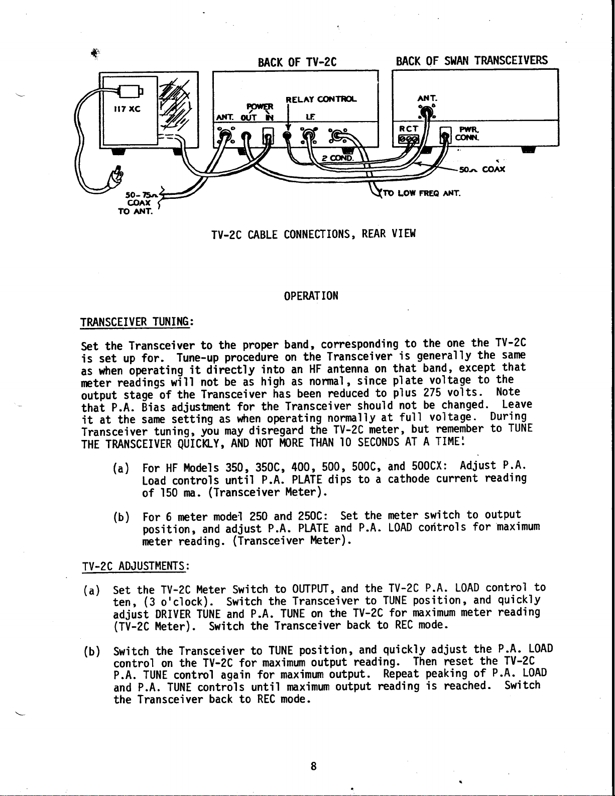
TV-zC CABLE
to the
Tune-up
proceduy.e
it dirictly
will
not
Transceiver
the
be
adjustment
seiting
QltCtC-v,
as
y6u
may disrbgard
AND NgT
u
|
CONNECTIONS,
OPERATION
proper
ai
for the
band, corresponding
the
on
into an
high as
has
HF antenna
normal
been reduced
Transceiver
when operating
the
MgRE THAN
VIE}I
REAR
Transceiver
that
on
since
,
plate^voltage to
plus
to
should
nonrnlly
TV-2C
I0
at
meter,
SECgNDS
FREQ ANT.
LOW
one
the
to
generally
is
band,
volts.
275
be changed._
not
voltage.
full
remember
but
TIME:
A
AT
q
@Ar(
5Oa
TV-2C
the
the
except
the
Note
Duringto
same
that
Leave
TUNE
(a)
(b)
TV-2C
(a)
Set
ten,
adjust
(TV-2C
(b)
Switch
control
P.A.
and
the
For HF
l4odels 350,350c,400,500,500c,
Load controls
150 ma.
of
For 6 meter
position,
meter
and adjust
reading.
ADJUSTMENIS:
TV-2C
the
(3
o'clock).
Meter
DRMR TUNE and
Meter).
the Transceiver
the TV-ZC for
on
TUNE
contrcl again
P.A. TUNE controls
Transceiver
until
P.A.
(Transceiver
rnodel 250
and
P.A.
(Transceiver
Switch
Switch
Switch
to OUTPUT,
the
TUNE on
P.A.
Transceiver
the
TUNE
to
maximum
for maximum
until
back
REC mode.
to
PLATE
dips
l4eter).
250C:
Set
PLATE and
l''leter).
and
Transceiver
TV-2C
the
back
position,
output
reading.
output.
maximum
output
500cx:
and
to a cathode
meter
the
P.A. L0AD
TV-2C
the
TUNE
to
switch
coritrols
P.A.
position,
for maximum
mode-
REC
to
an{-quickly
adiust
Then reset
Repeat
rcading
peaking
is
Adiust
current
to output
for maximum
L0AD
and
meter
the
of
reached.
P.A.
reading
control
quickly
reading
P.A. LOAD
TV-2C
the
P.A.
Switch
to
L0AD
Page 10

(c)
TU-ZC BIAS
pressing
barrier-Balance
P.A. BIAS
meter. Note
this
adjustment.
ADJUSTMENI:
Push-to-Ta'lk
the
control
back
that
on
the
control
Switch
button on
for Carrier
of
TV-2C meter
the
the
TV-2C
Transceiver
mic on
the
Null,
switch
(minimum
60 ma.
for
must
normal
to
models),
most
carrier).
reading
in CATHODE
be
mode.
SSB
adiust
the
on
position
Then
TV-2C
(BV
the
set the
for
(d)
TV-zC
properly
be betwlen
the
about
LEAK-THROUGH:
I.F.
Very
mfd.
Transceiver,
strong
you
thai
iorin!
Sypass iapacitors
signals
If
strap
braib
a
trom
the
of
CIRCUIT
following
The
different
a
to
CATH0DE
Transceiver
125
signals
aie
iniough
in the I.F.
from the
strap,
or
ground'iod
trap.
I.F.
MODIFICATIONS
CURRENT:
adjusted,
igO and
MIC. GAIN
MIC. GAIN
ma.
in the I.F.
hlaring a
at ifie
described
as
transceiver
about
chart
I.F.
Transceiver
1/2
water
or
WHEN
indicates
range.
After
normal cathode
ma.
200
weak 2
to the
range
rneter
Auxiliary
before
are
chassis
inch wide.
pipe.
CHANGING
both the
in TUNE
for
an
setting
range
slgni'l
freqiency.
still
to
Refer
I.F.
what
changes
the
Transceiver
current
position.
average
will
may'leak-through,
Relay
leaking through,.connect
the
Also conneg!
to
RANGE:
reading g!
TU-ZC
normally
when
Transverter
in fact
Be. sure
Switching
the alignment
must
be
and
the
In SSB
Cathode
be
a
made
Transmit
about
giving
it
connect
to
terminals
chassis.
good
section
in the
TV-2C
Meter
9 to
is a very
ground line to
TV-2C have
meter
mode' adiust
reading
l0
o'clock.
impression
the
strong
three
the
inside
short
a
may
This
for adiustment
TV-2C
when
been
will
of
the
ground
be copper
the chassis
converting
signal
.01
09
CRYSTAL
See
RANGE
I.F.
l4 mc.
2l
I
l
i
1
r
+i
28
50 mc.
After
to
Ll01
(sro1
mc.
mc.
I
making
adjust
ind L702.
the circuit
eich of
Refer
43 approx.
4l approx.
39 approx.
31.333
changed
the
to
the
FREQ.
chart
changes
pg.
wtren
circuits;
alignment
5
changing
that
section
c'|08
(Across
1802
None
None
5pf
?o
I.F.
permeability
is:
instructions.
for
cl
(Across
o'r
Lr
)
None
None
None
pt
ranger-it
5pf
)
will
tune
c707
(Across
1708
pf
20
None
None
(
None
jumper
half
L702)
be necessary
coils
connect
across
coil
of
1802'
?t
Page 11

ALIGNMENT
accurately
An
io align
r.V-U.
the
ior
uied
except
same
riiirur
iitoiiiiioi,
oscillators,
EQUIPMENT:
follow1ng
The
VTVM
l.
Watt
Z.
watts or
0utput
calibrated
the
inii
Vru
on
alignment
can
Dip Osci'llator
Grid
Transverter.
couple
thb
to
Grid
using
the
lRFrgRriate
oibiliator.
Dip
be accomplished
coveri.ng.the
the.Gria
Dtp on1.y.
coil
For those
with a
meter
necetl3ty
and
as
CAUTION
lmit'
thi's
i'n
used'
Dangerous
ALL safety
Pa*iiuLirt'i
tutk eireui-t.
fi.naltutkeireui.t|hieLdedeontpehnentTti'ththe
PoDe"
grom'd
off
filter
eormeeted
equiprnent
-
Hewlett
meter
more
meter
High
sLQpLA
iFti"
uiih
wi'l'l
Packard
with a
at
on
VoLtages
pineeautions
z'tnen aQjusting
Neuer
energiied.
tttwti-ng
eqaeitors
the
necessary
be
4]0B or
non-inductive
.l44
the
.l48
to
Transverter.
a"e
must be
eoupling
toueh
pouer supply
p.a.
anything
Short
before
tank
to
equiva'lent.
load.
mc.
You
at
used
inside
ei'reuit
tank
off
touehing
eirewLt'
properly
Must
may use
t.g1zs'
aL-L
to
finciE"
the
bLeed
to
anything
align
be capable
dunrmy
a
The,
the circuits
tune
without
fo]lows.
to
Transverter.
the
of
load
frequencies
procedure
Grid
handfing
the
and
is
Dip
125
following
The
'1.
Grid
equi
Electron'ic
Z.
mc. to
30
ALIGNMENT:
Disconnect
l.
Insert
Z.
chassi
OSCILLAT0R
a.
H'i , Low,
s.
Transverter
Set
-'l
on
Connect
coil
mc.
50
and
off
check
using
equipment
gscillator
Dip
ent.
val
Counter,
.|48
screen
Q]:
volt
probe
form,
Adjust
on
frequency
counter,
voltage
and
sca'l!.
DC
to
except
see that
to
desirable
is
(GD0)
or accurate
mc.
line
Mid range
crystal
Connect
I of
Pin
50
for
tor
|AOS
crysta'l
to see
receiver,
jf
not
but
-
Measurements
receiver,
final
from
crystals
Low
switch
mc. I"F,
maximum
or
to
ground lead
-Set
Vl.
'indication
comes
crystal
GD0.
is
necessary.
Corporation
to check
P.A. at
'in
crysta'l
frequency
to
L80'l
of
core
core
Set
on
every
on
in fact on
Model
actual
Pin 3,
V4
sockets
crystal.
Transverter
even
l/4"
VTVM.
time.
proper
on
with
in winding
Switch
If
59 or
frequencies
Pin
V3
and
of
top
VTVM
Set
chassis.
top of
for
voltage
available'
overtone'
from
7.
tfre
Page 12

Make same
b.
crystal
connections
switch
to
as
frequency
Hi
in
(a)
crystal.
above,
except.
switch
Transverter
While
c.
voltage
crystil,
as
If
I.F.
Set
a.
4
foi'miximum
see that
Repeat
b.
switch
Switch
c.
in tracking
Since
d.
Completely
denser
TRANSMITTER
switching
necessary
necessary
RANGES
VTVM to
gang
tuning
(a)
on
between
the
to-1/2
MIXER:
between
indicaiion
while
then
same
for
slightly
AT 14,21,
-]0
volt
condenser
indication
frequency
above,
Hi crystal,
can
50
close
with
(a)
be achieved.
I.F.
mc.
Cl04,
open.
Hi and
with
VTVM
on
switching
voltage
adiust
MC.:
28
and
scale,
DC
(Driver
VTVM.
on
tines
is 3
gang
4
and adjust
(b)
and
Adjust
adjustments
requires
then
crystals,
Low
either crystal.
between
indication
C805
and
Tune)
crystal
tuning
only
back
Ll0l
Hi and
best
for
move
'll4
equipment
If
overtone.
condenser
C'104
instead
one
I l/4
off
maximum
for
adiust
Low
VTVM
on
balance.
probe
open.
uhtil
no
crystal,
turnsr
indication
C805
Peak
crystals,
with
Pin
to
Adiust.
is available
3/4,open,
1101.
of
further
proceed
Sgt
for same
1802
either
Y2.
2 of
core of
crystal
improvement
as
gang..-con-
4
on
on Low
readiust_
crystal.
Set
Ll0l
check
VTVM.
to
follows.
is necessary
It
Transceiver
See
Transceiver
Set
a.
open.
vbtt
maximum
b.
c.
-
TRANSMITTER
a.
OC
frequency
that
Repeat
transm'itter
maximum
for
Switch
repeat
DRIVER:
Re-connect
connect
ind
fliin voftagei
DC.
b.
volts
Adj ust
adj ust
provide
to
operating
Connect
scale.
indication
(a)
above,
and
indication
Transceiver
(a)
and
screen
probe
Transceiver
of
core
drive
instructions,
and
probe
'
Energize
oi
.|44
is
except
Transverter
and
(b)
adjustments
wire
to
but
on,
and
L302
the
from
Transverter
VTVM to
on
transmitter
VTVN.
mc.
on
Transverter
to
swinger
If equipment
4
that
set
VTVM.
until
Pin 7.
v3,
on
Traismitter
Transverter
maximum
for
Transceiver
for
set
and
mc.
144
for
Pin I
gang
i4B mc.
[o
from
3 of
or
adiust
and
condenser
Low
proper
set
pot
bias
not
for
rise
at
keyed,
144
VTVM.
on
for the
CW output.
Set
V3. Leave
is available,
vTVM
9919-
is set
Tune
to Hi
tracking
to
rear
adiust
mc.
Key transmitter
(Approximately 8 volts)
follwing
gang
4
of
to 3/4
C207
instead
ends
is achieved.
-.|00
Transverter'(R{3)'
of
bias
STEP
condenser
VTVM on
for
L202
check
of
volts
to
open,
of L202,
band,
DC scale.,
pot
for
and
and
l/4
-10
see
and
-30
c.
Adjust
adj ust
Transceiver
C303
for
and
maximum
Transverter
on
rise
11
for
VTVM.
on
148 mc.
transmitter
Key
and
d
Page 13

switching
d#
"
unti'l
between
tracking
Low
and
Hi
is achieved
end
of
band,
adjust
as
in
(b)
and
(c)
above'
P.A.
a.
FINAL:
Re-connect
meter
avai'lable,
indication.
and
ma.
60
posit'ion
Adiust
b.
resonate
and
ment'is
If
may
Do
Adiust
c.
oulput
screen
antenna
to
use
adjust
load
unable
be
not
Bias
cathode
of
the
on
Transceiver
final
interact,
noted).
to
necessary
REMow\1LTAGESuIDDISCHARGEFTLIEICAPA?ry2RS
BEFonEI1U1HINGFINALTANKcIRct]II,AS800v2LlS
IS
DC
overcouple
coupling
is ichiEved
wire
iack
the
with
control
Transverter'
tank
fu]1y
to
CONNECIED
between
to
on-"eai
output
."vitii-in
no
on
current
Transverter
and
cit.Lil.
".lpeip
ro
'load
f inal
adiust
lO
poor
as
indicated
as
Transverter.
of
t.t."
as-inaicated
EINAL
signal
1303
on
Oscillator
of
r.ur
Rep'lace
-foia
ieverat
(at
,
coup'ling
CAUTION
TANK
and
by
Pin-3.
v4,
connect
Transverter
the
rransverter
by
crystal
'148
for
fina'l
times
least
between
CIRCUIT.
result'
may
140'l
re-resonat'ing
'
meter'
watt
50
circu'it,
cathode
th9
'
mc.
c'ircuit
tank
until
ma.
]80
1402
watt
If
a
as
key
chassis
current
transmjtter
Key
(Final
further
no
cathode
of
1403.
and
C303
meter
load
ohm
watt
and
not
is
relat'ive
transmitter
(Ra03)
fot:
switch
and
plate
improve-
current),
until
it
maximum
Re-peak
d.
set
e.
p.A.
output
1302.
this
At
f.
maximum
either
at
operation
g. check
Check
h.
mal-adiust.J,
RECEIVER
The
ALIGNMENT:
following
l. Siqnal
ruit-u.
trirmer
a'I1
contro'rs
ail
Tune.
output
carrier
equipment
Adiust
watt
on
pojnt,
Srtpui
end,
is
Generator,
iapable
condensers
Low
for
core
meter
it may
at
but
intended
in
ba1ance.
oi
Uv
boih
for
middle
ini"e
necessary
is
Measurements
covering
of
maximum
for
band,]44
of
end
maximum
in"lgoz
iiighi.adiustment
necessary
be
"nai-oi-uui,a.
s'imilar
one
at
band.
of
If
exclssive
is
tor
output
of
end
It
signal
for
Corp
mc'
14
to
band
should
will
capier
a'lignment
Model
to
watt
output
mc.
output gn
of
slight'ly.qdiYs!
iot idiust
Do
near
as
only'
equal
null,
not
leak thru'
of
80
.|48
mc.
on
Resonate
y3lt
Ll01'
cores
or
in
for-maximum
possible, unless
ai
exceed
or
is tak'ing
set
ver
recei
equiva1ent.
meter'
fina'l
meter.
1801
rcui
c'i
'load
L202'
to
band
and
ba]ance
output
edges'
off
.
ts
Generator
and
Peak
all
'is
,
2.
VTVII'I,
AC
Hewlett
Packard
4'l0B
equivalent'
or
L2
Page 14

0scillator
a.b.Since
alignment
the
section,
During alignment of
Tune
Transverter
of
has
a'lready
been adiusted
no further adjustment or
receiver,
peaked
at the
CAUTION
keep
P.A. Plate
frequency
in
alignment
Transceiver
of
Transmitter
the
is necessary.
being used
Driver
and
for adiustment.
DURTNG ALTGNMENT 0F THE
IRANSMTTTER,
ESAIPMENT
c. Iniect a
Increase
.|44
level
frequency.
TV-2C)
d.
of
erator
Adjust
for maximum audio
level
Potentiomenters
signal.
Adjust
e.
variable capacitors
adjustments 3 or 3
Coils 150'l and 1502
f.
replaced.
coils
peaking
figure
Reconnnended
9.
These
for response at
low
at
enough
control 3/4 to
control.
condi ti on
The
.
AS DAMAGE
mc. signal
until
Adjust
in
all fol'lowing
signal
core
times
should
factory adiusted
or
to
are
be
.|46
high end
noticable.
proceedure
full
only
on,
inconvience
RECETWR,
IUv
into the
is heard
in L702
or
"S"
RESULI r0 rHE
.|44
(I.F.
Meter
D0 NoT
mc. antenna
in Transceiver at
output
level.
adiustments,
R503 and
as
R504 for'maximum
and C702 for
C604
they
interact slightly
never need adiustment
by spreading or
mc. These coils
level
lack of
not
by reducing
band will
of
best noise figure
for
and adiust
is
the
KEY
rEST
input connector
coil
in
Reduce
necessary.
as
response
maximum
due
unless
broad enough
are
effect
is
sensitivity
run the
to
"S"
Meter readings
proper
the
receiver
signal
sect'ion
gen-
to a weak
response.
Repeat
to close coupling.
damaged or
squeez'ing
the
that
or noise
volume
in
this
R.F. Gain
the
audio
15
ra
Page 15

'&
____,
PIN #
V1
u?
V3
V4
T
R
T
T
T
Qr
Q2
1
I
*-2
.38
*-2.12
*1.29
-..l
9
.6AC
I 2
T
R
T
R
E
*-5
*-5.9
*-6.5
*-6.6
?
.35
.4.|
-7
.12
0
*-33.
.9
3
TV-zC
*-8.0
*-8.0
*-9
*-9.9
3
5.3AC
5.3AC
0
-19
?58
VOLTAGE
B
.8
4
.6AC
I 2
.6AC
I 2
12.64C
I 2.6AC
.23
c
0
0
0
0
CHART
Transistors
'l
Pin
choke
tr
213
241
r
3.gAC
0
FiI
,
CT
Pin
Q1
measured
is series
6
74
83
5.3AC
2s0
*-33.3
l, and
with
with
7
0
0
237
190
0
Q2
A200
meter
uHY
8
tBl
2s0
Pl ates
lead'
9
0
NC
800vDc
Q3
Q4
Q5
measurements
Al.f
r,{easurements
;;;;;:
*
These
vary
May
+9
+8.8
+l'l
made
-iii.
r.s-unv
points
as
by
.8
mirch
+5
+5
+.7 0
+
are
with
.nor.6
.4
.6
10%
20,000
+l
+l
on
.5
.5
ohms
all
greatly effected
under
30%
as-
+.l.52
+l
.54
+.7
per
volt-meter.
points except
RF
by-crystal
different
condit'ions.
those
activity
point
From
noted above'
proximity
and
indicated
test
of
to chassis
lead'
etc'
14
Page 16

PARTS
LIST
CAPAC
CIA/ClB/ClC
cl 0l
Cl02
Cl03
Cl04
cl05
Cl06
Cl07
Cl0B
Cl09
c20l
I
I
a
ITORS
50,
.00.l,
.00.l, 20%
20,
.01,
.00.l, 20% 500V
.00.l,
Factory Selectabl
Factory Selectable
50,
c202
c203
75,
75,
.|000,
c204
5
12,
.00.l,
20,
.00.|,
]00,
.0.|,
60,
.0'l
,
.00.|,
.0.|,
MF, I 50V Ei ectrol
l0
.|000'
.|000,
.00],
l0/.|0
.|000,
35,
50,
.00.|
30,
27,
50,
.|00,
.|000
.0.|,
'100,
50,
.|000,
c205
C206
C207
C208
c301
C302
C303
C304
C305
c401
C402
C403
C404
C405
C406
C407
c408
C409
C4l0
c4l l
c412
c4t 3
C4l4
C4l
C4l6
c50l
c502
C503
C504
C505
C506
c60l
C602
.01',
.0.|,
]000,
270,
.|000,
c603 .01,
l5 Var.
DMl
5
Disc
500V
20%
Disc
500V
Mica Comp.
+gg-20%,
Trinrner
500V
Disc
20% 500V
Disc
DMI 5
DMls
DMI 5
DM20F
DMls
20% 500V
Mica
Comp.
Disc
Trirrner
20% 500V Disc
DMI 5
+80-20%,
Mica Comp.
+gg-20%,
20% 500V
+80-20%,
500V
Trimmer
500V
Disc
500v
Feedthru
Feedthru
20% 500V
Disc
Variable
Feedthru
APC
6KV, N]500,
20% 500V
,
D'isc
DMl 5
DMls
DMls
Mica Comp.
Feedthru
+80-20%,
5
DMl
DMl5
Feedthru
+gg-20%'
+80-20%,
Feedthru
DMls
Feedthru
+80-20%,
500V
500V
500V Disc
500v
Disc
e
Disc
Disc
Disc
Yt'ic
D'isc
Trimmer
Disc
Disc
Disc
074-019
088-002
072-006
072-006
089-003
072-023
072-006
072-006
088-002
088-003
088-003
088-022
088-035
072-006
089-003
072-006
088-004
072-023
089-006
072-023
072-006
072-023
073-0]
I
077-00.l
077-001
072-006
074-03.l
077-002
074-032
084-0.|
3
072-006
088-00r
088-023
0BB-002
089-005
077-00.|
072-023
088-004
088-002
077-00.|
072-023
072-0?3
077-001
088-0.|
4
077-001
072-023
C604
C605
C606
C607
c70l 50,
C702
C703
9704
C705
C706
C707
C80l
c802
c803
c804
CB05
cB06
cB07
cB08
I I .6 , Vari abl
.|000,
.0.|
.|000,
.|.|.6,
.0.|
.001
.|
000,
.002,
Feedthru
+80-20%,
,
Feedthru
DMI 5
Variable
+80-20%,
,
20%
,
Feedthru
20%
Factory Selectable
.00], 20%
.l2,
DMl5
+80-20%,
.0.|
,
DMI 5
470,
Mica
ll5,
DMl5
75,
.|00,
DMls
]00, DMls
RES I STORS
Rt0t 27K
Rl02
56
Ohms
Rl 03 I 50K
Rt04
Rl05 47 Ohm
Rl06 47 Ohm
R20l
R202
loK 2l,l
47K
lhn
220
lt^l
lt^l
R203 220 lhn
R204
R205 56 Ohm
R206
R207
R30l
R302
R303
R40'l
R402
R403
R404 1 Ohm
R405 360 Ohm
R406
R407
R50l
220 }hn
I 8K
lK
I 50K
27K
12K 2W
I K
4.7K
Pot.
25K
5%
.|00
Ohm
I 5K
]M
2W
R502 2.2t4
R503 250K
Pot.
e
500V
500V
500V
Comp.
Ztt
2W
2W
Zw
5%
D'isc
500V
D'isc
500V
D'isc
Dt'sc
Disc
D'isc
500v
Trimmer
075-0.|
6
077-001
072-023
077-001
088-002
075-0.|
6
072-023
072-006
-001
077
072-0.l
8
072-006
088-035
072-023
088-045
089-007
088-003
088-004
088-004
042-273
042-560
042-154
044-l 03
043-470
043-470
042-473
044-Z?1
044-221
044-221
044-560
042-r 83
042-102
042-154
042-273
044-123
042-102
04?-47?
052-038
049-01
9
046-361
042-l
0l
042-l 53
042-t 05
042-?25
052-045
15
*
Page 17

.#
BESIST0RS
R504
R505
R50l
R602
R603
R604
R605
R606
R70't
R702
R703
R704
R80l
R802
R803
RB04
R805
R806
VACUUM
vl
u2
v3
v4
*
Ohms
330
5%
180
lM
2.2]4
5%
180
250K
l0l.l
loK
330
680
'100K
470
47 Ohms
3.3K
8.2K
470
4.7K
33K
470
TUBES
6JK6
128Y7
6360
58948
Pot.
Ohms
Ohms
Injection
Transm'it
Driver
Power
Amp.
Mixer
ifier
Ampl
042-33'l
046-t
042-1
8'l
05
042-225
8l
046-1
052-045
049-003
042-331
042-681
04
042-l
042-471
042-472.
042-332
042-822
042-471
042-472
042-333
042-471
472-043
472-002
472-050
472-036
RELAY
]2VDC
K]
3P2T
COILS/CHOKES
Plate
Amp
0l
Ll
L20l
L202
L30l
1302
L40l
L402
1403
1404
1405
1406
L50l
1502
160'l
1602
L70l
L702
L80l
1802
Inj.
UH
.2
Trans.
'l
.8 uh
Dri
Final
Fi nal
Antenna
.? uh
.2 uh
1.5
First
First
.|.8
Second
Rec.
Rec.
0sci
Tripler
Mixer
Coi'l
ver
Grid
Amp
uh
R.F.
R.F.
uh
Mixer
Mixer
I'l ator
R.F.
.
PickuP
Coil
Coil
Coil
coil
P'l
InPut
0utPut
InPut
0utPut
Coi
Co
ate
0utPut
I
-015
I'r1
012-09'l
027-019
01?-092
027-0'18
Sl,lAN
'l
i
Sl.lAN
St^lAN
ShlAN
027-0.l
027-019
0?7-020
Sl^lAN
SI^lAN
027-0.l
S!'fAN
SWAN
01 2-093
0l 2-089
01 2-090
9
8
TMNSISTORS
Q'l
Q2
Q3
Q4
Q5
2N706
2N706
40673
40673
40673
LAMP
GEt 8l
METER
MI
5
DIODES
D40'l
060'l
ShlITCHES
sl
s2
."s3
I i ator
Osci
pl
Tri
First
Second
Rec.
I N34A
Zener
2W
12U
Meter Switch
Crystal
ON-OFF
Se'lector
er
Amp.
R.F
R.F.
M'ixer
Amp.
476-001
476-001
476-012
476-012
476-012
47'l-005
'n
2-008
475-008
475-020
't
-058
7t
't7't-059
-075
r
7t
16
Page 18

.ft
'lt
ll.lCTRONlCS
SWAII
ACAII{ST
TI,'BTS,
ttOB
tyICE
lrOR A PERIOD
PT'NCEASD.
ts
CAND
wlTEIN
IACTORY
LIrITTD
PARTS,
PBI@
AIYD tS
WITE IiISUSD,
WANBANTY
CONFORAIION
DEIECIIS
TRANSTIITORS,
TIIIS
PROPERLY
DAYS
TlE{
WTTTTOT.N
TO HFAIRING
IN
WANRANTT
III&ID
OT
PRIOR
VALID
NqT
POLICY
WANRAIqTS
WOru<MANSEP,
IIATEnIAL
AND
ONE
OF
DATE OT
AI,ITEORTZATION.
OR NTPIACING
IT
DAMACID.
OR
ON
DIODIS.
TROM
YEAR
VALTD
tS
AI{D MAII.IO
IN
PI'RCRASE.
TIIE EQI'IPUIIIT
T'NDER
ONLY
DO
ONLY
SwAn
ELECTRONICS
OCEANSIDE, CALIFORNI.A
@rlp.lrrloa
Cublc
A StlDeklltrl
ol
TEIS
NON,UAI'
DATD OI
TE
IT
TE
TO
NOT S@
WARBA!TT
TES
TED
EAS
!$NPUBTT
EXCIFT
ORIGINAL
II{CLOSID
TACTORY
TO IE
DTDCTTVI
BEf
T}rB'
IS
TAI'
Page 19
E
I
5
I
iat-t2
st
fcliffi3
||OTE
EII
ETl
9t
o
la
I
al
IOT8
9l
I
I
i:-
Page 20
I
I
sd
clo4-rl
.
-tHt,
!r
f,
:
,ml
l,ffi
:
=
'lH
-llr
.o'
Dtrvlt
=
ruxtx(,
I
=
,
!ffitl0 DUOil - i[
IJCmtB
ts
ffi ff-t fr@ aIW mlw
-
s.udd..
ru!.
Page 21
I
I
iF
I
I]
c:ot-ts
-l
:!o!
i-l
t:t
tn
tt
I8
,
t,
?u|.lrao
Ditvli
3
c.o-.or
,_.-i._.
-it1
caol-pn7
| ,
I I
tr
-
lTr-ffiI
s
?
q
a
B
j
?t
Ht'
(#-),
-{H
l,5'
sl J8
==
='
rl
1=
lc.os..@
tji,
c ao6-.ol
-,lR?O?-tooKlx^
i
H".ft-
r
if
-I
=
=
"i
:
+
ffirlc Ulm
&S Mr6
-
-
t[
qoda..
PE 0-e
cdl.
mG ttMD
mm
Page 22
,tFa
l'
'lH
J2
rFT-ffi|
Eu!!reg!!3!l
JI
rrEQ.l
LOw
I
lAt{tEiffA
{<
I
ITO
,l
Yl^istlvlR
I
tv.lc
tt9;r n o77 F6rgr
 Loading...