

Sven Power Pro 800, Power Pro 650, Power Pro 425, Power Pro 1400, Power Pro 1000 User Manual [ru]
Page 1
Интерактивный
источник
бесперебойного
питания
ИНСТРУКЦИЯ ПО эксплуатации
POWER PRO
Перед эксплуатацией системы внимательно ознакомьтесь с настоящей инструкцией
и сохраните ее на весь период использования
Рус
Page 2

ИНСТРУКЦИЯ ПО ЭКСПЛУАТАЦИИ
Благодарим Вас за покупку источника бесперебойного питания ТМ SVEN!
ПРЕДУПРЕЖДЕНИЕ ОБ ОГРАНИЧЕНИИ ОТВЕТСТВЕННОСТИ
Несмотря на приложенные усилия сделать инструкцию более точной, возможны некоторые несоответствия. Информация
данной инструкции предоставлена на условиях «как есть». Автор и издатель не несут никакой ответственности перед лицом
или организацией за ущерб или повреждения, произошедшие от информации, содержащейся в данной инструкции.
ТОРГОВЫЕ МАРКИ
Все торговые марки являются собственностью их законных владельцев.
РАСПАКОВКА
Аккуратно распакуйте ИБП. Проверьте устройство на предмет повреждений. Если ИБП поврежден, сразу же обратитесь
к дилеру. Если ИБП был поврежден при транспортировке, обратитесь в фирму, осуществлявшую доставку. Рекомендуем Вам
сохранить весь упаковочный материал для возможной транспортировки.
АВТОРСКОЕ ПРАВО
© Перевод Sven Corp. 2004
Данная инструкция и содержащаяся в ней информация защищены авторским правом. Все права оговорены. Версия 1.1 (v 1.1).
Техническая поддержка размещена на сайтах: http://www.sven.ru, http://www.atri.ru
2
Page 3

Рус SVEN Power Pro
СОДЕРЖАНИЕ
1. Введение ...................................................................................................................................................................... 4
2. Меры безопасности .................................................................................................................................................... 4
3. Комплектация ............................................................................................................................................................. 4
4. Особенности интерактивных ИБП ............................................................................................................................. 4
5. Условия эксплуатации и хранения ............................................................................................................................. 4
6. Установка и подключение ИБП ................................................................................................................................... 5
6.1. Подключение .......................................................................................................................................................... 5
6.2. Подзарядка аккумуляторной батареи ..................................................................................................................... 5
6.3. Подключение оборудования к ИБП ......................................................................................................................... 5
6.4. Проверка работоспособности ИБП ......................................................................................................................... 5
6.5. Перегрузки и короткое замыкание на выходе ......................................................................................................... 5
6.6. Подключение устройства защиты от выбросов в телефонном/сетевом кабеле ...................................................... 5
7. Модели 425, 650 и 800: управление и индикаторы.................................................................................................. 6
8. Модели 1000 и 1400: управление и индикаторы...................................................................................................... 8
8.1. Установка и замена аккумуляторов ......................................................................................................................... 9
9. Решение возможных проблем ................................................................................................................................... 10
10.
Технические характеристики и таблицы индикации ................................................................................................ 11
3
Page 4

ИНСТРУКЦИЯ ПО ЭКСПЛУАТАЦИИ
4
1. ВВЕДЕНИЕ
Интерактивный источник бесперебойного питания Sven Power Pro, созданный на основе новейших технологий
микропроцессорного управления, обладает самыми современными функциями. Автоматическое регулирование напряжения
(функция AVR) позволяет входному напряжению изменяться от 70 до 130% от номинала. Циклическая функция самопроверки
предназначена для контроля работы как ИБП, так и состояния аккумуляторов.
ИБП серии PRO – это идеальное оборудование для защиты наиболее чувствительных потребителей (компьютеров и
периферийных устройств: мониторов, дисковых подсистем, модемов, стриммеров и т. п.). В случае сбоев электроснабжения
ИБП продолжает питать подключенное к нему оборудование, используя энергию внутренних аккумуляторов и производя при
этом визуальную и звуковую индикацию, которая заблаговременно предупреждает Вас о неполадках в системе
электроснабжения.
2. МЕРЫ БЕЗОПАСНОСТИ
Устанавливайте ИБП в закрытых помещениях с контролируемой температурой и влажностью воздуха.
Не открывайте аккумулятор: вытекший электролит опасен для кожи и глаз.
Отключайте ИБП от сети перед подключением кабеля к компьютеру и шнура питания к сети для уменьшения риска
поражения электрическим током.
Отсоедините от сети шнур питания и выключите ИБП в аварийной ситуации.
Розетка для подключения должна находиться вблизи от устройства и быть доступной.
Обслуживать ИБП и отключать внутренний источник питания (аккумулятор) должен только квалифицированный
специалист.
3. КОМПЛЕКТАЦИЯ
1. Интерактивный источник бесперебойного питания — 1 шт.
2. Силовой кабель — 1 шт.
3. Интерфейсный кабель — 1 шт.
4. Программное обеспечение — 1 диск
5. Инструкция по эксплуатации — 1 шт.
Примечание.
Программное обеспечение размещено на сайтах: http://www.sven.ru, http://www.atri.ru
4. ОСОБЕННОСТИ ИНТЕРАКТИВНЫХ ИСТОЧНИКОВ БЕСПЕРЕБОЙНОГО ПИТАНИЯ
Подстройка диапазона входного напряжения для более полного соответствия особенностям
местной сети
Автоматическое регулирование напряжения — АVR (интерактивный тип)
Автоподстройка на частоту сети 50/60 Гц
Микропроцессорное управление
Двунаправленный коммуникационный порт RS232
Разъем подавления импульсов для защиты сетевого оборудования (модема)
Режим экономии энергии
Улучшенное управление состоянием батарей (АВМ)
Холодный старт
Автоматическая зарядка батарей при выключенном ИБП
5. УСЛОВИЯ ЭКСПЛУАТАЦИИ И ХРАНЕНИЯ
Не эксплуатируйте ИБП в помещениях, где температура окружающего воздуха не соответствует приведенной в разделе
«Технические характеристики».
Условия хранения
ИБП должен храниться закрытым в вертикальном положении в сухом прохладном месте с полностью заряженным
аккумулятором. Перед тем как поставить ИБП на хранение, зарядите его в течение 4 часов. Затем во избежание истощения
аккумулятора отключите кабели, подключенные к порту интерфейса компьютера.
Длительное хранение
При длительном хранении в условиях температуры окружающей среды от +15 до +30°С аккумулятор ИБП следует
перезаряжать через 6 месяцев.
При длительном хранении в условиях температуры окружающей среды от +30 до +45°С аккумулятор ИБП следует
перезаряжать через 3 месяца.
Page 5

6. УСТАНОВКА И ПОДКЛЮЧЕНИЕ ИБП
6.1. Подключение
Выставьте 4 DIPпереключателя, расположенные на задней панели, в соответствии с выбранным вариантом настройки ИБП
(режим сохранения энергии, номинал входного напряжения, установка частоты).
Сетевой шнур, который использовался для питания компьютерного оборудования, переставьте во входной разъем ИБП, а
освободившийся входной разъем компьютерного оборудования подключите к одной из выходных розеток ИБП сетевым
шнуром из комплекта поставки.
Подключайте ИБП только к двухполюсной, с третьим заземляющим проводом, розетке. Крайне нежелательно использовать
удлинители и переходники. Шнур питания от источника к розетке не должен превышать 10ти метров.
6.2. Подзарядка аккумуляторной батареи
ИБП поставляется с полностью заряженными внутренними аккумуляторами. Однако аккумуляторы могут потерять часть
заряда во время транспортировки и при хранении, поэтому следует провести подзарядку аккумуляторов, оставив ИБП
подключенным к сети на 8 часов. Аккумуляторы автоматически подзаряжаются, если ИБП подключен к сети.
6.3. Подключение оборудования к ИБП
Для того чтобы быть уверенным, что компьютерное оборудование будет защищено при отключении и ожидаемое время
автономной работы обеспечено, необходимо оценить суммарную мощность подключенного к ИБП оборудования. Требуемая
суммарная мощность должна быть меньше или равняться нагрузочной способности ИБП, в противном случае ИБП издаст
звуковой сигнал и загорится желтый светодиод.
Примечание.
Расчет мощности подключаемой к ИБП нагрузки.
Для того чтобы ИБП работал надежно в течение длительного времени, по данной формуле подберите необходимую
мощность подключаемого оборудования.
Рн * 1,66 * 1,25 Рибп
Рн — активная мощность нагрузки в Вт.
1,66 — коэффициент пересчета активной мощности в полную мощность.
1,25 — коэффициент запаса. В некоторых случаях можно брать и 1,1.
Рибп — полная мощность ИБП в В*А. Обычно стоит в маркировке модели.
6.4. Проверка работоспособности ИБП
Подключите ИБП к сети переменного тока, включите силовой выключатель ИБП и компьютерное оборудование. На передней
панели должен загореться зеленый светодиод ОТ СЕТИ.
Для проверки работоспособности ИБП отсоедините входной сетевой шнур для имитации сбоя сетевого напряжения. В этом
случае ИБП должен немедленно переключиться в автономный режим и продолжать питать оборудование от внутренних
аккумуляторов. Работая в автономном режиме, ИБП каждые пять секунд будет издавать короткий звуковой сигнал,
напоминая, что оборудование питается от ограниченного по времени источника энергии. Восстановите питание ИБП от сети,
вставив на место входной сетевой шнур. Повторите этот тест четырепять раз.
Работоспособность ИБП можно проверить, нажав и удерживая кнопку ВКЛ/ВЫКЛ/ТЕСТ на передней панели не менее двух
секунд, затем отпустить ее для запуска процедуры самодиагностики. ИБП переключится в автономный режим с питанием
подключенного оборудования от внутренних аккумуляторов и выполнит процедуру самотестирования.
6.5. Перегрузки и короткое замыкание на выходе
Если суммарная потребляемая мощность Вашего оборудования больше, чем нагрузочная способность ИБП, то может
сработать автоматический предохранитель на задней панели, при этом ИБП будет пытаться обслужить нагрузку, используя
внутренний источник энергии. Перед тем как выключиться и обесточить подключенное оборудование, ИБП будет издавать
продолжительный звуковой сигнал. Желтый светодиод зажжется и будет гореть до следующей попытки включения. В этой
ситуации выключите ИБП и решите, какое оборудование можно оставить незащищенным, затем отключите его от ИБП. После
устранения причины перегрузки или короткого замыкания найдите на задней панели автоматический предохранитель и
вдавите вовнутрь выскочившую вставку. Затем включите ИБП снова.
Примечание.
Не подключайте лазерные принтеры к ИБП. Мощность потребления лазерного принтера гораздо больше, чем нагрузочная
способность этого ИБП.
6.6. Подключение устройства защиты от выбросов в телефонном/сетевом кабеле
Подключите телефонный кабель или 10 BaseT сетевой кабель в гнезда устройства защиты от выбросов на задней панели
ИБП. Комбинированный модуль гнезд RJ45/RJ11 допускает подключение всех стандартных разъемов телефонной линии и 10
BaseT сетевых кабелей. Кабель от АТС или кабель от локальной компьютерной сети подсоедините к разъему с обозначением
IN. К разъему с обозначением OUT подключите защищаемое оборудование.
Примечание.
Это соединение для использования ИБП является необязательным.
5
Рус SVEN Power Pro
Page 6

ИНСТРУКЦИЯ ПО ЭКСПЛУАТАЦИИ
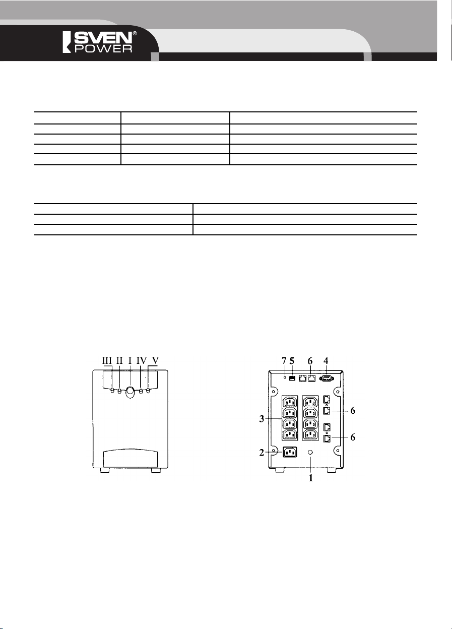
7. МОДЕЛИ 425, 650 И 800: УПРАВЛЕНИЕ И ИНДИКАТОРЫ
* Внешний вид панелей модели 425
Передняя панель. Задняя панель.
* Внешний вид панелей моделей 650 и 800
Передняя панель. Задняя панель.
(I)КНОПКА ВКЛ/ВЫКЛ/ТЕСТ
Включение ИБП
Эта кнопка управляет подачей энергии к входным и выходным розеткам ИБП. Если нажать эту кнопку и удерживать ее, то
динамик издаст звуковой сигнал длительностью 0,2 секунды сразу после нажатия, два коротких звуковых сигнала на второй
секунде удержания и три коротких звуковых сигнала на третьей секунде, индицируя время удержания кнопки.
Тест самодиагностики на переменном токе
Отпустите кнопку, ИБП включит подачу мощности на выход. Для предотвращения случайных включений ИБП игнорирует
любые нажатия кнопки, если время удержания менее 0,2 секунды или более 4 секунд.
Если включить ИБП, когда сетевое напряжение в норме, то ИБП на 5 секунд перейдет в автономный режим работы, чтобы
выполнить тест самодиагностики при включении, а затем вернется в режим питания нагрузки от сети.
Холодный старт
При отсутствии входного напряжения позволяет запустить ИБП в автономном режиме.
Тест самодиагностики
Нажмите и удерживайте кнопку в течение 23 секунд, когда сетевое напряжение в норме. ИБП будет имитировать отключение
сети и выполнять процедуру самодиагностики.
Управление звуковой сигнализацией
При отсутствии электроэнергии в сети ИБП будет издавать короткий звуковой сигнал каждые пять секунд. Нажмите и
удерживайте кнопку в течение 23 секунд, звуковой сигнал отключится.
6
Page 7

Рус SVEN Power Pro
(II) СВЕТОДИОД ОТ СЕТИ/АВТОНОМНО
Индикация неисправности в сети
В нормальном режиме работы этот индикатор будет гореть непрерывно. Во время отсутствия электроэнергии в сети ИБП
будет издавать короткий звуковой сигнал каждые пять секунд, а светодиод будет мигать в такт звуковым сигналам.
Предупреждение о низком уровне заряда аккумуляторов
В состоянии низкого уровня заряда аккумулятора ИБП издаст непрерывный звуковой сигнал и светодиод будет мигать.
После того как ИБП выключится, желтый светодиод (III) будет мигать без звукового сигнала.
Управление интервалом предупреждения о низком уровне заряда аккумуляторов
Интервал времени, в течение которого выдается предупреждение о низком уровне заряда аккумуляторов, по умолчанию
выбран с определенным запасом, чтобы в любой операционной системе было достаточно времени для закрытия файлов и
корректного завершения работы. При желании, если установленный интервал времени предупреждения о низком заряде
аккумуляторов значительно больше, чем требуется, можете уменьшить интервал в два раза нажатием и удержанием кнопки
ВКЛ/ВЫКЛ/ТЕСТ в течение трех секунд, но не более четырех. И таким же образом можете вернуться к длительности,
установленной по умолчанию.
Режим экономии энергии
Если к ИБП не подключена нагрузка и произошло отключение энергоснабжения, ИБП будет издавать два коротких звуковых
сигнала каждые 5 секунд в течение 10 минут, затем выключится для экономии энергии аккумуляторов. Чтобы “разбудить”
ИБП, нажмите кнопку ВКЛ/ВЫКЛ/ТЕСТ.
(III) СВЕТОДИОД ПЕРЕГРУЗКА/ПРОВЕРЬ АККУМУЛЯТОР
Индикация перегрузки
При перегрузке ИБП издает непрерывный звуковой сигнал и этот светодиод загорается, указывая на перегрузку.
Индикация необходимости замены аккумулятора
Когда аккумулятор приходит в негодность, ИБП издает четыре коротких звуковых сигнала каждые три секунды и этот
светодиод начинает мигать, указывая на то, что аккумулятор непригоден для эксплуатации и должен быть заменен.
(1) ВХОДНОЙ АВТОМАТИЧЕСКИЙ ПРЕДОХРАНИТЕЛЬ
Автоматический предохранитель срабатывает, разрывая входную цепь ИБП, если нагрузка превышает его нагрузочную
способность.
(2) ВХОДНОЙ РАЗЪЕМ
Тип входного разъема IEC 320 (вилка). Используйте входной сетевой шнур для соединения ИБП с сетью электроснабжения.
(3) ВЫХОДНОЙ РАЗЪЕМ
Тип выходного разъема IEC 320 (розетка). Используйте выходной сетевой шнур для подключения Вашего оборудования
к ИБП. Количество выходных розеток смотрите в разделе «Технические характеристики».
(4) РАЗЪЕМ DB9
Разъем DB9 позволяет соединить интерфейсным кабелем (из комплекта поставки) ИБП с портом RS232 вашего компьютера.
Использование программного обеспечения «Power Manager» автоматически сохраняет файлы и отключает компьютер при
длительном отсутствии питания.
Примечания:
1. Это соединение не является обязательным.
2. Проконсультируйтесь у Вашего дилера о порядке установки программного обеспечения для мониторинга ИБП
в операционных системах, используемых Вами.
(5) 4 DIPПЕРЕКЛЮЧАТЕЛЯ
Переключатели установлены в положение по умолчанию. Установки переключателей 2, 3 и 4 должны соответствовать
напряжению и частоте местной сети электроснабжения.
Режим экономии энергии
Переключатель 1 разрешает/запрещает режим сохранения энергии аккумуляторов. Если к ИБП не подключена нагрузка и
произошло отключение энергоснабжения, ИБП будет издавать два коротких звуковых сигнала каждые пять секунд в течение
10 минут, затем выключится для экономии энергии аккумуляторов.
Переключатель 1 Режим экономии энергии
Вкл. Запрещен
Выкл. Разрешен
7
Page 8
ИНСТРУКЦИЯ ПО ЭКСПЛУАТАЦИИ
Настройка номинала входного напряжения
Переключатели 2 и 3 управляют установкой номинального входного напряжения. Изменяя установки, Вы можете сдвигать все
напряжения переключения (верхний и нижний предел входного напряжения или пороги повышения/понижения при работе от
сетевого напряжения) до ± 40 В исходя изза особенностей местного электроснабжения.
Переключатель 2 Переключатель 3 Напряжение сети
Вкл. Вкл. 200 В
Вкл. Выкл. 220 В
Выкл. Вкл. 230 В
Выкл. Выкл. 240 В
Установка частоты напряжения в сети
Переключатель 4 задает установку по умолчанию для частоты переменного напряжения сети электроснабжения.
Переключатель 4 Частота напряжения в сети
Вкл. 50 Гц
Выкл. 60 Гц
(6) ПОДАВЛЕНИЕ ВЫБРОСОВ В ТЕЛЕФОННОЙ ЛИНИИ/СЕТЕВОМ КАБЕЛЕ
Комбинированный модуль разъемов RJ45/11 используется для защиты от выбросов 10 BaseT сети/ одинарной телефонной
линии.
Примечание.
Это соединение не является обязательным.
(7) КНОПКА СБРОСА (Reset) ПРОЦЕССОРА
Если ИБП не работает должным образом, перезапустите ИБП, нажав кнопку сброса Reset.
8. МОДЕЛИ 1000 И 1400: УПРАВЛЕНИЕ И ИНДИКАТОРЫ
* Внешний вид панелей моделей 1000 и 1400
Передняя панель. Задняя панель.
Примечание.
Элементы управления и индикаторы на задней панели соответствуют моделям 425, 650 и 800.
(I) КНОПКА ВКЛ/ВЫКЛ/ТЕСТ
Включение ИБП
Эта кнопка управляет подачей энергии к выходным розеткам ИБП. Если нажать эту кнопку и удерживать ее, то ИБП издаст
звуковой сигнал длительностью 0,2 секунды сразу после нажатия, два коротких звуковых сигнала на второй секунде
удержания и три коротких звуковых сигнала на третьей секунде, индицируя время эффективного контактирования кнопки.
Отпустите кнопку, ИБП включит подачу мощности на выход. Для предотвращения случайных включений и связанных с ними
разрядов аккумуляторов ИБП игнорирует любые нажатия кнопки, если время контактирования менее 0,2 секунды или более
4 секунд.
8
Page 9

Рус SVEN Power Pro
Тест самодиагностики на переменном токе
Если включить ИБП, когда сетевое напряжение соответствует норме, то ИБП на 5 секунд перейдет в автономный режим
работы, чтобы выполнить тест самодиагностики при разгоне, а затем вернется в режим питания нагрузки от сети.
Холодный старт
При выключенном ИБП нажмите кнопку во время отключения энергоснабжения. ИБП начнет питать сам себя и свои выходные
розетки.
Тест самодиагностики
Нажмите и удерживайте кнопку в течение 23 секунд, когда сеть функционирует нормально. ИБП будет имитировать
отключение сети и выполнять процедуру самодиагностики.
Управление звуковой сигнализацией
При отсутствии электроэнергии в сети ИБП будет издавать короткий звуковой сигнал каждые пять секунд. Нажатие и
удержание кнопки в течение 23 секунд позволит снять звуковой сигнал.
(II) СВЕТОДИОД ОТ СЕТИ
В нормальном режиме работы этот индикатор будет гореть непрерывно. Если работает автоматический регулятор
напряжения, то этот светодиод будет мигать.
(III) СВЕТОДИОД АВТОНОМНО
При работе от аккумуляторов этот светодиод горит и ИБП каждые 5 секунд издает звуковой сигнал. Если уровень заряда
аккумуляторов станет опасно низким, звуковой сигнал ИБП перейдет в непрерывный и будет продолжаться либо до
появления сетевого напряжения, либо до отключения ИБП изза полного истощения аккумуляторов.
Интервал времени, в течение которого выдается предупреждение о низком уровне заряда аккумуляторов, по умолчанию
выбран с определенным запасом, чтобы в любой операционной системе было достаточно времени для закрытия файлов и
корректного завершения работы. При желании, если установленного по умолчанию запаса значительно больше, чем
требуется, пользователь можно уменьшить интервал в два раза, нажав и удерживая кнопку ВКЛ/ВЫКЛ/ТЕСТ в течение трех
секунд, но не более четырех. Таким же образом Вы можете вернуться к длительности, установленной по умолчанию.
Если к ИБП не подключена нагрузка и произошло отключение энергоснабжения, ИБП будет издавать два коротких звуковых
сигнала каждые пять секунд в течение 10 минут, затем выключится для экономии энергии аккумуляторов. Чтобы «разбудить»
ИБП, нажмите кнопку ВКЛ/ВЫКЛ/ТЕСТ.
(IV) СВЕТОДИОД ПЕРЕГРУЗКА
При перегрузке ИБП издает непрерывный звуковой сигнал и этот светодиод загорается, указывая на перегрузку. Как вывести
ИБП из состояния перегрузки, смотри п. 6.5.
(V) СВЕТОДИОД ПРОВЕРЬ АККУМУЛЯТОР
Если аккумулятор выходит из строя, ИБП издает четыре коротких звуковых сигнала каждые три секунды и светодиод горит
непрерывно, указывая на то, что аккумулятор непригоден для эксплуатации и должен быть заменен. Если запас энергии
аккумуляторов достигнет нижнего предела, этот светодиод начнет мигать.
Если ИБП обнаружит какуюлибо неисправность собственных компонентов, загорятся все светодиоды и непрерывный
звуковой сигнал будет звучать в течение 10 секунд, после чего ИБП выключится.
8.1. Установка и замена аккумуляторов
Замена аккумуляторов безопасная процедура, не связанная с риском поражения электрическим током. Вы можете даже
оставить ИБП и нагрузки включенными, выполняя следующую процедуру. Захватите верх передней крышки и наклоните ее на
себя и вниз. Чтобы открыть доступ к дверце батарейного отсека, снимите низ крышки от шасси и подымите ее вверх, при
этом не натягивайте провода и не касайтесь открытой печатной платы. Положите переднюю крышку наверх. Отверните два
винта дверцы батарейного отсека и откройте ее. Захватите выступ и аккуратно вытащите батарею аккумуляторов из ИБП.
Отсоедините выводы батареи. Вытащите две клеммы по отдельности, чтобы отсоединить батареи. Присоедините выводы
батареи к новой батареи. Плавно вставьте батарею в ИБП, закройте дверцу батарейного отсека, закрутите на место винты
дверцы батарейного отсека, поставьте на место переднюю крышку.
Примечание. При соединении батареи с силовыми низковольтными кабелями возможно небольшое искрение контактов.
9
Page 10

ИНСТРУКЦИЯ ПО ЭКСПЛУАТАЦИИ
9. РЕШЕНИЕ ВОЗМОЖНЫХ ПРОБЛЕМ
Примечание.
На работу ИБП в некоторых случаях может влиять качество электропитания: отсутствие заземления, неверное подключение
фазы и нейтрали.
10
подключенным к ИБП.
процессора ИБП.
1. Нажмите кнопку Reset.
2. ИБП подлежит ремонту.
включите
Замените батареи.
Page 11

Рус SVEN Power Pro
10. ТЕХНИЧЕСКИЕ ХАРАКТЕРИСТИКИ И ТАБЛИЦЫ ИНДИКАЦИИ
Технические характеристики моделей 425, 650 и 800
11
Page 12

ИНСТРУКЦИЯ ПО ЭКСПЛУАТАЦИИ
Таблица индикации для моделей 425, 650 и 800
Технические характеристики моделей 1000 и 1400
12
Page 13

Рус SVEN Power Pro
Таблица индикации для моделей 1000 и 1400
13
Page 14

ИНСТРУКЦИЯ ПО ЭКСПЛУАТАЦИИ
Примечания:
1. Технические характеристики, приведенные в спецификации, справочные и не могут служить
основанием для претензий.
2. Продукция торговой марки SVEN постоянно совершенствуется. По этой причине технические
характеристики могут быть изменены без предварительного уведомления.
14
Page 15

Eng SVEN Power Pro
Uninterruptible
Power
System
Please read this operation manual before using the unit and retain this operation manual
in safe place for future reference
Page 16

USER’S MANUAL
Thanks for your purchasing the Sven Power Pro UPS product. Please read the USER’S
MANUAL before using the Sven Power Pro UPS product.
INFORMATION TO USER
Changes or modifications to this equipment not expressly approved by the party responsible for compliance could void the user’s
authority to operate the equipment.
UL WARNING STATEMENT
See the «INSTALLATION AND SAFETY INSTRUCTIONS» section in page 18.
16
Page 17

Eng SVEN Power Pro
TABLE OF CONTENTS
1. Introduction ................................................................................................................................... 18
2. Installation and Safety Instructions ...................................................................................................... 18
3. 425, 650 & 800 Controls and Indicators ................................................................................................ 20
4. 1000 & 1400 Controls and Indicators .................................................................................................... 22
5. 1000 & 1400 Battery Installation/Replacement Procedure ........................................................................ 23
6. Trouble Shooting ............................................................................................................................. 23
7. Specifications and Indication Table ...................................................................................................... 24
17
Page 18

USER’S MANUAL
1. INTRODUCTION
The UPS is a extremely reliable standby uninterruptible power system designed to keep computers and peripheral devices such as
monitors, storage subsystems, modems, tape drives, etc performing from utility line failures which could result in damage of data In
the event of utility failure, the UPS supplies power to your equipment derived from a battery within the UPS and provides visual and
audible indicators which alert you to utility line failures therefore the user has ample time to save file and close operations Whenever
the UPS is plugged in, the UPS maintains the battery in a charged condition and serves to protect your equipment from surges and
noise brought from utility
The main features include:
Advanced equipment & data protection from blackouts, brownouts, sags, AC line noise and surges
Adjustable input power range settings to meet your power source requirement
Full analytical high performance micro processor control with true RMS synchronous calculation
Intelligent battery management for battery status, battery power saving & battery replacement control
DC direct start up capability, MS NT communication ready, complete diagnostic indication and control
2. INSTALLATION AND SAFETY INSTRUCTIONS
Receiving Inspection
Once you have received the UPS, you should remove and inspect the unit for shipping damage. If damage is found, immediately noti
fy the carrier and your dealer. The carton and foam materials in which the UPS was shipped to you were designed with great care to
provide protection from transportation related damage. You should keep both the shipping carton and the packing foam in case the
UPS must be returned to the factory for service (damages sustained in transit when shipped from the user are not covered under war
ranty).
Important Safety Instructions
[Instructions Importantes Concernant La Securite]
Save these instructions — This manual contains important safety instructions [conserver ces intructions. Cette notice contient des
instructions importantes concernant la securite.]
All safety and operating instructions should be read before operating your UPS. These UPS units are intended for use in a tempera
turecontrolled, indoor area free of conductive contaminants. Select a location which will provide good air circulation for UPS at all
times.
For the first time use, your unit should be plugged in (the power I/O switch does not have to be on) for at least 8 hours to
fully charge the battery.
CAUTION
A battery can present a risk of electrical shock, bum from high shortcircuit current. Observe proper precautions. Une batterie peut
presenter un risque de choc eletrique, de brulure par transfer! d’energie. Suivre les precautions qui s’imposent.]
When replacing batteries use the same number and the following type batteries given in the Specifications section of this manual.
CAUTION — Proper disposal of batteries is required. Refer to your local
codes for disposal requirements. [ATTENTION: L’elimination des batteries est reglementee. Consulter les
codes locaux a cet effet.]
18
Page 19

Eng SVEN Power Pro
1. Conditions
Do not operate the UPS in an environment where the ambient temperature is outside the limits given in the specifications of this manual.
2. Connection to the utility
There is a 4dip switches located on the rear panel and set to the default position applicable to your power source voltage and fre
quency requirement. Check with your dealer for the right setting before you proceed the installation procedure.
240/230/220/200 Vac Version
The 240/230/220/200 Vac version UPS is furnished with one output power cords for connection to computer equipment having «IEC
320» male appliance couplers at their input. In most cases this will not be a problem as the input cord which currently powers your
computer equipment may be swapped with one of the supplied output cords. Hence, the swapped output line cord can be used
instead as the input line cord for the UPS.
3. Initial battery charging
The UPS is shipped from the factory with its internal battery in a fully charged state. However the battery may be lose some charge
during shipping and storage. The battery should be recharged before conducting the following. Test for proper operation and to ensure
that UPS will provide expected run time. The battery is automatically charged by the UPS whenever the UPS is plugged in (the power
1/0 switch does not have to be on). You can be sure that the battery is fully recharged if the UPS is left plugged in for at least 8 hours
4. Connecting your equipment to the UPS
To ensure that your computer equipment will be protected during a utility failure and that you receive expected run time, it is important
that you determine the total power needs of the equipment you wish to protect with the UPS. The power requirements of your equip
ment should be less than or equal to the capacity of the UPS. The UPS will emit a loud tone and the yellow LED will illuminate to alert
you of the overload. Consult your dealer foi the power requirement of your equipment
Once you have determined that your equipment and the UPS are compatible, plug your equipment into the UPS’s real panel output
receptacles.
5. Test for proper operation
Turn on the UPS’s power I/O switch and switch on your computer equipment. The green NORMAL indicator at the front panel should
be illuminated and your equipment should operate normally.
To test the operation of the UPS, simply unplug its input cord to simulate a utility blackout. The UPS will immediately transfer your
equipment loads to power derived from the UPS’s internal battery. During this time the UPS will emit a beep once every five seconds
to remind you your equipment is operating from a source of power that is limited in duration. Restore power to the UPS by plugging in
the line cord. Repeat this test four or five times to ensure proper operation.
Another way to test the operation of the UPS, simply press and hold the ON/OFF/TEST button for 2 sees more then release it at the
front panel to run a selftest routine. The UPS will transfer your equipment to power derived from the UPS’s internal battery and run
selftest. See the following section if abnormal operation is encountered.
6. Overloads & output shorts
If the total power requirement of your equipment is much greater than the capacity of the UPS, the UPS s rear panel circuit breaker
may trip. Once the breaker is tripped, the UPS will attempt to operate the load using its internal power source and emit a loud tone
before the UPS shuts down and ceases to power your equipment. The yellow led will illuminate and stay on to alert you of the overload
till the UPS starts up again In this case turn off the UPS and decide which equipment will be left unprotected by the UPS. Find the input
circuit breaker on the rear panel and reset the breaker by pressing the plugger of the breaker after the overload or short circuitry is
released. Then start up the UPS again Do not plug laser printers into this UPS. The power requirements of a laser printer is much larg
er than the capacity of this UPS.
7. Connect Telephone/Network Surge Suppression (optional)
Connect a single line telephone or a 10BaseT network cable into the telephone/network surge protection sockets on the back of the
UPS. The RJ45/RJ11 modular combination sockets accept all standard single line telephone and lOBaseT connections. The cable
coming form the telephone service or networked system is connected to the port marked «IN», the «OUT» port is connected to th
equipment to be protected.
Note: This connection is optional and not needed to use the UPS.
19
Page 20

USER’S MANUAL
3. 425,650 & 800 CONTROLS AND INDICATORS
* 425 Panel Diagram
Front Panel Rear Panel
* 650 & 800 Panel Diagram
Front Panel Rear Panel
(I) ON/OFF/TEST:
The button controls power to the UPS and its output receptacles. The alarm will emit a beep during the first .2 sec contact (continu
ous press & hold the button) then two short beeps at the 2nd sec and three short beeps at the third sec to indicate the effective con
tact time.
Press the button, the UPS will power on its output after releasing the button. The UPS will ignore any switch on contact that contact
time is 0.2 sees less or 4 sees more to avoid the unnecessary battery drain. Power on the UPS!
Switch on the UPS when the utility is normal, the UPS will transfer the load to the internal battery power to perform the diagnostic self
test at boost for 5 sees then return the load to the AC utility. AC start up self{test feature!
Switch on the button during a utility power outage and the UPS is off, the UPS will start to power on itself and its output receptacles.
DC start up feature!
Press and hold the button for 2 sees and less than 3 sees when utility is normal, the UPS will simulate the utility outage and perform
self test function It provides a convenient means of testing the UPS s battery. Self test feature!
During a utility power outage the UPS will emit one beep once every five seconds Pressing and hold the button for 2 sees and less than
3 sees and UPS will silence the beep. Alarm disable control!
(II) ON{LINE/ON{BATT LED:
When operating normally this indicator will always stay on During a utility failure the UPS will emit a beep every five sees and this LED
will blink at alarm beeping. Utility failure indication!
During a low battery condition which means that the UPS’s usable battery capacity is nearly spent the UPS will emit a constant beep
and both LED will blink After the UPS shut down, the yellow LED stay blink w/o beeping. Low battery warning!
The low battery warning interval is default to be a reasonable period where it takes longer for computer systems to save files and close
operations User may reduce the interval half via pressing the on/off switch more than 3 sees and less than 4 sees during UPS s on
batt operation User may extend back to the default vice verse. Low battery warning interval control!
When operating UPS with no equipment load during a utility power outage the UPS will emit two beeps once five sees then shut itself
down to save battery energy after ten minutes To wake up the UPS, press the button. Power saving!
20
Page 21

Eng SVEN Power Pro
(Ill) OVLD/ CHECK ВАТТ LED :
During an overload operation, the UPS will emit a loud tone and this LED stays on indicating an overload occurs See the Installation
section 6 to recover the UPS from overload operation. Overload indication!
When the battery goes bad, the UPS will emit four short beeps every 3 sees and this LED blinks indicating the battery is no use and
must be replaced. Battery replacement indication!
(1) IINPUT CIRCUIT BREAKER:
The UPS will trip the breaker when loads exceed the UPS’s capacity The resettable plugger extend when tripped
(2) AC INPUT SOCKET:
One standard IEC 320 male socket Use an input line cord to connect UPS
to the utility
(3) OUTPUT SOCKET:
Standard reverse female IEC for 200V series Use an output line cord to connect your equipment to the UPS See the section of speci
fications for the numbers of sockets
(4) RS232 PORT:
The UPS's RS232 port is the means by which your UPS communicates with a computer system There are two computer port connec
tion. Windows NT protocol and standard RS232 protocol, supported by the UPS Check your dealer for various operating system UPS
monitoring support.
Note: This connection is optional and not needed to use the UPS. The UPS works properly without a connection.
(5) 4 DIP{SWITCHES:
The switches are set to the default position as supplied from the factory The setting of switch 2 3 & 4 must match your local voltage
and frequency source Check your dealer for the appropriate setting All the optional settings are listed as follows
The switch 1 disables the setting for the power saving feature When operating UPS with no equipment load during a utility power out
age the UPS will emit two beeps once five sees then shut itself down to save battery energy Power saving’
Switch 1 Power Saving Feature
on disable
off enable
The Switch 2 & 3 control the setting for the nominal input voltage Changing the setting, you may shift all switching voltages [like high
and low input voltage limit or booster and buck (optional) for online operation] up to + or 40V to meet special power need in com
monapplication.
Switch 2 Switch 3 Power Source Volt
on on 200 V
on off 220 V
off on 230 V
off off 240 V
The switch 4 controls the setting for the input power frequency default.
Switch 4 Power Source Frequency
on 50 Hz
off 60 Hz
(6) TELEPHONE/NETWORK SURGE SUPPRESSION :
The RJ45/11 module connectors are used for 10 BaseT network/single line telephone surge protection.
Note: This connection is optional and not needed to use the UPS. The UPS works properly without a connection.
21
Page 22

USER’S MANUAL
4. 1000 & 1400 CONTROLS AND INDICATORS
* 1000 & 1400 Panel Diagram
Front Panel Rear Panel
(I) ON/OFF/TEST:
The button controls power to the UPS and its output receptacles The alarm will emit a beep during the first 2 sec contact (continuous
press & hold the button) then two short beeps at the 2nd sec and three short beeps at the third sec to indicate the effective contact
time.
Press the button the UPS will power on its output after releasing the button The UPS will ignore any switch on contact that contact time
is 0.2 sees less or 4 sees more to avoid the unnecessary battery drain. Power on the UPS!
Switch on the UPS when the utility is normal the UPS will transfer the load to the internal battery power to perform the diagnostic self
test at boost for 5 sees then return the load to the AC utility. AC start up self{test feature!
Switch on the button during a utility power outage and the UPS is off, the UPS will start to power on itself and its output receptacles.
DC start up feature!
Press and hold the button for 2 sees and less than 3 sees when utility is normal, the UPS will simulate the utility outage and perform
self test function It provides a convenient means of testing the UPS’s battery. Self test feature!
During a utility power outage the UPS will emit one beep once every five seconds Pressing and hold the button for 2 sees and less than
3 sees and UPS will silence the beep. Alarm disable control!
(II) ON{LINE LED:
When operating normally, this indicator will always stay on. When the automatic voltage regulator is in operation, this LED will blink.
(Ill) ON{BATT LED:
In onbattery operation, the onbattery LED illuminates and the UPS will sound every 5 secs. The UPS will emit a steady tone when the
battery reserve runs low until AC returns or the UPS shuts down from battery exhaustion.
The low battery warning interval is default to be a reasonable period where it takes longer for computer systems to save files and close
operations. User may reduce the interval half via pressing the on/off switch more than 3 secs and less than 4 secs during UPS’s on
batt operation. User may extend back to the default vice verse When operating UPS with no equipment load during a utility power out
age, the UPS will emit two beeps once five sees then shut itself down to save battery energy after ten minutes. To wake up the UPS,
press the button
(IV) OVLD LED:
During an overload operation, the UPS will emit a loud tone. and this LED stays on indicating an overload occurs. See the Installation
section 6 to recover the UPS from overload operation.
(V) CHECK ВАТТ LED:
When the battery goes bad, the UPS will emit four short beeps every 3 sees and this LED stay on indicating the battery is no use and
must be replaced. When the energy reserve of the battery runs low, this LED will blink.
When the UPS detects a hardware fault, all LEDs will illuminate and the UPS will emit a steady tone for 10 secs then shuts down itself.
See the 425, 650 & 800 controls & indicators section for the corresponding controls & indicators of the rear panel
22
Page 23

Eng SVEN Power Pro
5. 1000 & 1400 BATTERY INSTALLATION/REPLACEMENT PROCEDURE
Battery replacement is a safe procedure, isolated from electrical hazards. You may leave the UPS and loads on for the following pro
cedure.
1. Grasp the top of the front cover and tilt it out and down.
2. Unhook the bottom of the cover from the chassis and lift it upward to expose the batten door Be careful not to strain the wires. Do
not touch’the exposed printed circuit board.
3. Fold the front cover on top of the UPS as shown.
4. Use a screwdriver or a coin to remove the two battery door screws and open the door.
5. Grasp the tab and gently pull the battery out of the UPS.
6. Disconnect the battery leads Pull the two couples apart to disconnect the battery.
7. Connect the battery leads to the new battery. Note: Small sparks at the battery connectors are normal during battery connection.
8. Slide the battery into the UPS. close the battery door, replace the battery compartment screws, and replace the front cover.
9. Dispose of the old battery properlv at an appropriate recycling facility or return it to the supplier in the packing material for the new
battery. See the new battery instructions for more information.
Battery Bank (Optional)
A special battery bank is available for 1000 & 1400 extended run time version. See your dealer for more information.
6. TROUBLE SHOOTING
23
Problem
UPS will not turn on or off.
All indicators are illuminate and the
UPS emits a constant tone.
UPS beeps and UPS operates on
battery even though normal line volt
age exists.
UPS does not have expected run
time. Low battery warning or UPS
transfer power to battery but imme
diately back to AC.
All indicators are off but the batt. bad
is blinking. no alarm and the UPS is
not operating.
Possible Cause
1. On/off/test button not pushed.
2. Output short or overload shutdown.
3. Computer interface or accessory prob
lem.
Internal UPS system fault.
1. Sags or spikes is found. UPS is briefly
transferring your equipment to its alter
nate power source due to utility voltage
sags or spikes.
2. Input circuit breaker is tripped.
3. The UPS has a bad inputconnection.
1. Low battery condition.
2. Bad battery.
The UPS is shut down and the battery is
discharged from an extended power out
age.
Action To Take
1. Press again.
2. Reduce the load then reset the breaker
by pressing the plugger back in.
3. Disconnect the interface then press the
CPU reset button.
1. Press Reset button.
2. Return for service.
1. This operation is normal. The UPS is pro
tecting your computer equipment from
abnormal utility voltages.
2. Reduce the load and reset the breaker.
3. Cheek the connection.
1. Remove all connected
2. Equipment and recharge
3. Battery for 8 hours.
4. Return for service.
None. The UPS will return to normal opera
tion when the power is restored and the
battery has a sufficient charge.
Page 24

USER’S MANUAL
7. SPECIFICATIONS AND INDICATION TABLE
425, 650 & 800 Specifications
24
Specification Pro 425 Pro 650, Pro 800
Capacity rating 425 VA 650 VA; 800 VA
Nominal input volt. 200, 220, 230, 240 user adjustable
Nominal input freq. 50. 60 Hz auto sensing, user adjustable default
Acceptable input volt. 0 33% over the nominal input voltage
On line input freq. limits +/ 5% over the nominal input freq.
Output voltage +/ 15% from the nominal input volt
Output frequency +/ 1 Hz from the nominal input freq.
Output wave form PWM. stepped wave approximation to sine wave
Continuous output capacity 425 VA. 35 min. 650 VA; 800 VA. 35 min.
Typical back up time 1522 min. 3040 min.
Transfer time 2 ms typical, 4 ms max.
Maximum load 425 VA/280 W 650 VA/400 W; 800 VA/500 W
Noise filter Full time EMI/RFl filtering, 100 kHz to 10 MHz
Surge energy rating 320 J 480 J
Surge current capability 4500 A 6500 A
Surge response time 0 ns normal mode, <5 ns common mode
Surge voltage let through 0.7% subject to IEEE 587 Cat. A 6 kV test
Processor RISC based micro processor
Detection
power source RMS value, locked phase, no load power saving, output load, opeat
ing temperature, bad battery, battery condition & system fault
Protection
overcurrent, shortcircuit, overload, lightening, surge, noise, sags, brownout,
blackout, input breaker, modem & 10BaseT
Battery type sealed and leak proof maintenance free leadacid
Alarm signals
Audible signals, 45 dBA at 1 meter
Battery capacity 12 V, 7 Ah 12 V, 11 Ah
Recharging time 4 hours typical, 10 hours max.
Communication port RS232, standard
Page 25

Eng SVEN Power Pro
425, 650 & 800 Indication Table
See the page 20. 425 and 650 & 800 panel diagram
25
Specification Pro 425 Pro 650, Pro 800
Interface connection support standard RS 232. Windows NT
Indicators two LEDs indicating online, onbatt. overload, bad batt & system fault
Input socket IEC 320 male
Output socket 2 Rev.IEC [NHMA515R] 3 Rev. IEC [NEMA515R]
Operating environment 040°C (32104°F), 095% RH. non condensing
Physical dimension WxHxD 97 x 141x 320 mm 122 x 141 x 398 mm
Weight 6 kg 8 kg; 8.5 kg
UPS Yellow LED (III) Green LED (II) Alarm UPS Status Indication
On X On X Utility Normal
On X Blink X Utility Failure
On On X X Overload
Off On Off X Overload
X Blink X X Low Battery Cut Off Event
On X Blink 2 beeps @ 5 sec. Power Savings
On X Blink 1 beep @ 5 sec. Utility Failure
On Blink Blink Constant On Battery Low
On On Blink Constant On Overload
On Blink On 4 beeps @ 3 sec. Battery Bad
On X Blink 3 beeps ® 5 sec. Monitor Overload
Off On On X System Fault
Page 26

USER’S MANUAL
1000 & 1400 Specifications
200, 220, 230 and 240 V
26
Specification Pro 1000 Pro 1400
Capacity rating 1000 VA 1400 VA
Nominal input volt. 200, 220, 230, 240 user adjustable
Nominal input freq. 50, 60 Hz auto sensing, user adjustable default
Acceptable input volt. 0 33% over the nominal input voltage
On line input freq. limits +/ 5% over the nominal input freq
Output voltage +/ 15% from the nominal input volt
Output frequency +/ 1 Hz from the nominal input freq
Output wave form PWM. stepped wave approximation to sine wave.
Continuous output capacity 1000 VA, 35 min. per batt. set 1400 VA. 35 min. per batt. set
Typical back up time 45 min. per batt. set 60 min. per batt. set
Transfer time 2 ms typical, 4 ms max.
Maximum load 1000 VA/670 W 1400 VA/950 W
Noise filter Full time EMI/R.FI filtering, 100 kHz to 10 MHz
Surge energy rating 480 J
Surge current capability 6500 A
Surge response time 0 ns normal mode, <5 ns common mode
Surge voltage let through 0.7% subject to IEEE 587 Cat. A 6 kV test
Processor RISC based micro processor
Detection
power source RMS value, locked phase, no load power saving, output load,
opeating temperature, bad battery, battery condition & system fault
Protection
overcurrent, shortcircuit, overload, lightening, surge, noise, sags, brownout,
blackout, input breaker, modem & 10BaseT
Battery type sealed and leak proof maintenance free leadacid
Alarm signals
Audible signals, 45 dBA at 1 meter
Battery capacity two 12 V, 11 ah; extendible two 12 V, 17 ah; extendible
Recharging time 4 hours typical, 10 hours max.
Communication port DB9, standard
Page 27

Eng SVEN Power Pro
1000 & 1400 Indication Table
See the page 22. 1000 & 1400 panel diagram
Packing contents
1.UPS — 1 pc
2. Output power cable —1 pc
3. RS232 cable — 1 pc
4. User manual —1 pc
5. UPS monitoring software CD —1 pc
27
Specification Pro 1000 Pro 1400
Interface connection support standard RS 232, Windows NT
Indicators fourLEDs indicating online, onbatt. overload, bad batt & system fault
Alarm signals audible signals. < 45 dBA at 1 meter
Input socket 1EC 320 male
Output socket 8 Rev.lEC[6NEMA515R] 8 Rev. IEC[6NEMA515R]
Operating environment 040°C (32104°F). 095% RH. non condensing
Physical dimension WxHxD 165 x 216 x 450 mm 165 x 216 x 450 mm
Weight 21 kg 28 kg
UPS Green
LED (III)
Green
LED (II)
Yellow
LED (IV)
Red
LED (V)
Alarm UPS Status Indication
On X On X X X Utility Normal
On X Blink X X X AVR Mode
On On X X X X Utility Failure
On X X On X X Overload
Off X X On X X Overload
X X X X Blink X Low Battery Cut Off Event
On X X X X 2 beeps @ 5 sec. Power Savings
On X X X X 1 beep @ 5 sec. Utility Failure
On X X Off Blink Constant On Battery Low
On X X On X Constant On Overload
On X X X On 4 beeps @ 3 sec. Battery Bad
Off On On On On X System Fault
Page 28

 Loading...