

Page 1

ARC 160-PFC Welding Machine
USER MANUAL
REVISION : 2016-03-30
Page 2

Page 3
Preface
This manual includes hardware description and operation introduction of ARC 160-PFC equipment.
For your and other people’s safety, please read the manual carefully.
Pay attention
Pay attention to the words after the signs below.
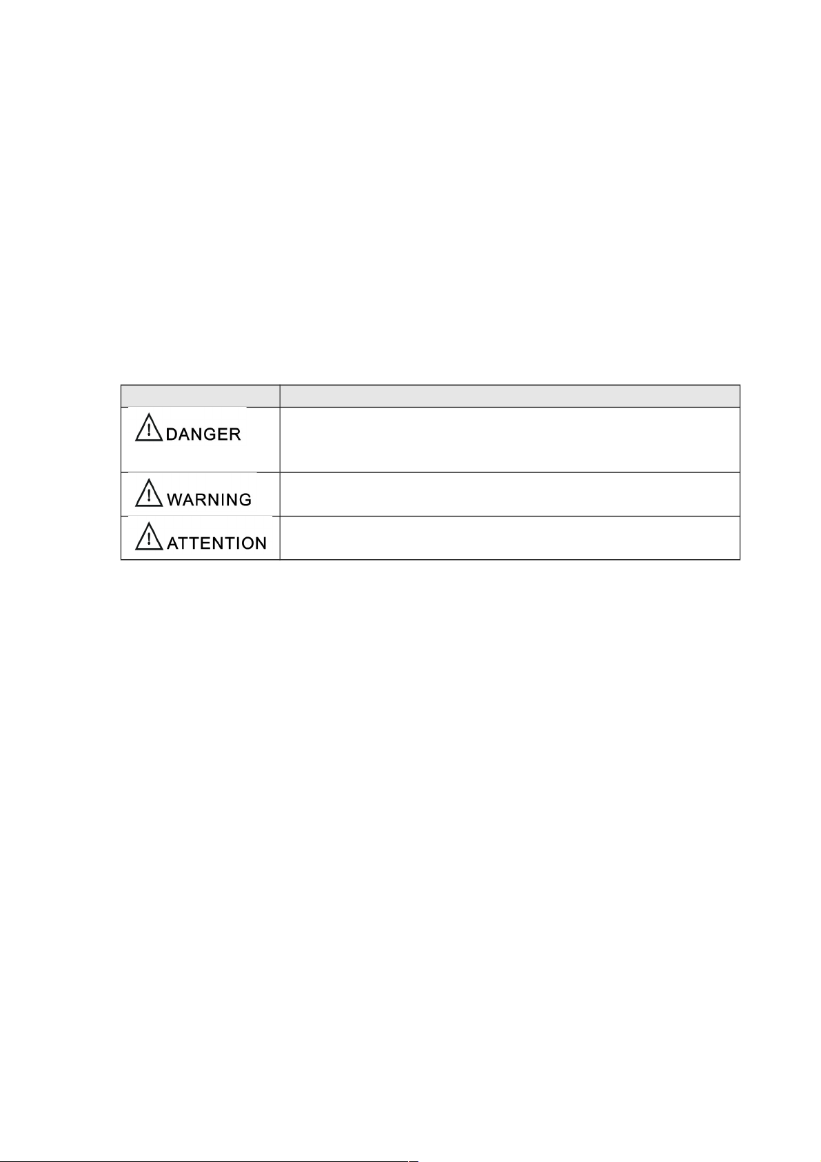
Sign Description
The words after this sign means there is great potential danger,
which may cause major accident, damage or even death, if it is not
followed.
The words after this sign means there is some potential danger,
which may cause hurt or property lose, if it is not followed.
The words after this sign means there is potential risk, which may
cause equipment fault or break, if it is not followed.
Version
Version YF-TAE-0001, A0, released at 30th, 03, 2016.
The contents of this manual are updated irregularity for updating of product. The manual is only
used as operation guide, except for other promises. No warranties of any kind, either express or
implied are made in relation to the description, information or suggestion or any other contents of
the manual.
1
Page 4

CONTENTS
1 Safety warning
2 Product
2.1 General
2.2 Technical data
3 Installation
2
Page 5
1 Safety warning
The safety notes listed in this manual is to ensure correct use of the machine and to keep you
and other people from being hurt.
The design and manufacture of welding machine considers safety. Please refer to the safety
warning listed in the manual to avoid accidents.
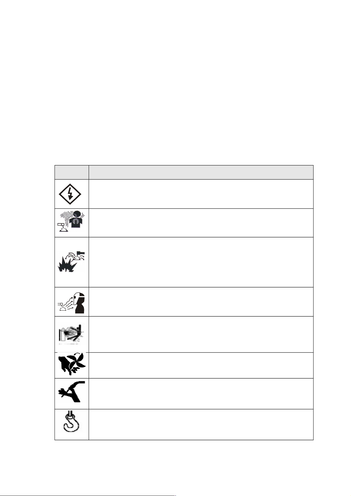
Different damage would be caused by wrong operation of the equipment as follows. Please read the user
manual carefully to reduce such damage.
Sign Description
Any contact of electric parts may cause fatal electric shock or burnt.
Gas and fumes are harmful to health.
Operation in narrow space may cause choke .
Spark and hot workpiece after welding may cause fire.
Bad connected cable may cause fire.
Uncompleted connection of workpiece side circuit may cause fire.
Never weld on the case of tinder stuff, or it may cause explode.
Never weld airtight containers such as slot, pipe etc., or it may break.
Arc ray may cause eye inflammation or skin burnt.
Spark and residue will burn your eyes and skin.
Toppling over of the gas cylinder will cause body hurt.
Wrong use of the gas cylinder will lead to high-pressure gas eruption
and cause human hurt.
Never let fingers, hair, clothes or etc. near the moving parts such as
the fan.
The wire shoot out of the torch may stab eyes, face and other naked
parts.
Never stand in front of the swang equipment or under it, or it may fail
and cause injury.
3
Page 6
Please follow the rules below to avoid heavy accidents.
Never use the equipment to do other things but welding.
Follow related regulations for the construction of the input-driven power source, choice of
place, usage of high-pressure gas, storage, configuration, safe-keeping of workpiece after
welding and disposal of waste, etc.
Nonessential do not enter the welding area.
People using heart pacemaker is not allowed to get close to the welding machine or area
without doctor’s permission. The magnetism created by energizing the welding machine
can have a bad effect to the pacemaker.
Install, operation, check and maintain the equipment by profession personnel.
Understanding the contents of the user manual for safety.
Please follow the rules below to avoid electric shock
。
Keep away from any electric parts.
Earth the machine and workpiece by professional personnel.
Cut off the power before installation or checking, and restart 5 minutes later. The
capacitance is chargeable device. Please ensure it has no voltage before start again even
if the power source is cut off.
Do not use wire with inadequate section surface or damage insulation sleeve or even
exposed conductor.
Do ensure well isolation of wire connection.
Never use the device when the enclosure is removed.
Never use broken or wet insulation gloves.
Use firenet when work at high position.
Check and maintain regularly, don’t use it until the broken parts are fixed well.
Turn off the power when not in used.
Follow the national or local related standard and regulations when using the AC welding
machine at narrow or high position.
Please follow the below notes to avoid fire and explode, etc.
No combustible in welding area.
Keep off combustible when welding.
Keep hot workpiece after welding away from flammable gas.
4
Page 7
Do move away the combustible around when weld the dooryard, ground and wall,.
The wire connection of base metal should be as close to the welding place as possible.
Never weld those facilities with gas pipe or airtight slot.
Put fire extinguisher around the welding area to prevent fire.
The gas and fumes are harmful to health, please wear protective
device according to regulations.
Wear exhaust equipment and breathe preventive facilities to prevent gas poisoning or
choke.
Use suggested part exhaust equipment and breathe preventive facilities to prevent hurt or
poisoning by gas and other powder, please.
To prevent oxygen-deficiency, air out the gas-filled room which is full of CO2 and argon on
the bottom, When operating on trunks, boilers, cabins, etc.
Please accept the supervisor’s inspection when operating in narrow space. Air the room
and wear breathe preventive facilities.
Never operate in degrease, washing or spray space.
Using breathe preventive facilities when weld shielded steel for it will cause poisonous dust
and gas.
The arc, spark, residue and noise are harmful to health, please wear
protective appliance.
Eye protection against arc is recommended when welding or supervise welding.
Please wear preventive spectacles.
Welder’s gloves, welder’s goggles, long sleeve clothes, leather apron, and other standard
protection equipments must be worn for welding operation.
A screen to protect other people against the arc must be set in the welding place.
Please follow the notes below to avoid gas cylinder toppling over or
broken.
Use the gas cylinder correctly.
Use the equipped or recommended gaseous regulator.
5
Page 8
Read the manual of gaseous regulator carefully before using it, and pay attention to the
safety notes.
Fix the gas cylinder with appropriate holder and other relative parts.
Never put the cylinder under high temperature or sunshine environment.
Keep your face away from the gas cylinder exit when opening it.
Put on the gas shield when it is not used.
Never put the torch on the gas cylinder. The electrode can not meet the gas cylinder.
Any touch of the switch part will cause injury, please note the
following.
Never use the machine when the enclosure is off.
Install, operate, check and maintain the machine by professional person.
Keep your fingers, hair, clothes etc. away from the switch parts such as the fan.
The wire end may deal damage, please note the following.
Never look into the electric conduction hole when checking the wire feeding is normal or
not, , or the shooting wire may stab your eyes and face.
Keep your eyes, face or other naked parts away from the end of torch when feeding the
wire manually or pressing the switch.
For better work efficiency and power source maintenance, please
note the following.
Precautions against toppling over.
Never use the welding equipment for pipe thawing.
Lift the power source from side when use the up-down forklift truck to avoid toppling over.
When using the crane for lift, tie the rope to the ears with an angle no more than φ15 to the
vertical direction.
When lifting the welding machine which equipped with gas cylinder and wire feeder,
download them from the power source and ensure the horizontal of the machine. Do fix the
gas cylinder with belt or chain when moving it to avoid body hurt.
Ensure fastness and insulation when lifting the wire feeder through the swing ring for
6
Page 9

welding.
Electromagnetic interference needing attention:
It may need extra preventive measures when the equipment is used in particular location.
Before the installation, please estimate the potential electromagnetism problems of the
environment as follows.
a) Upper and lower parts of the welding equipments and other nearby power cable, control
cable, signal cable and phone cable.
b) Wireless electric as well as TV radiation and reception equipment.
c) Computer and other control equipments.
d) Safety-recognition equipment etc. Such as supervise of industrial equipments.
e) Health of people around. Such as personnel using the heart pacemaker or audiphone.
f) Equipments for adjustment and measurement.
g) Anti-disturb capability of other used equipments .Users should ensure these equipments
and the environment are compatible, which may need extra preventive measures.
h) Practical state of the welding and other activities.
Users should observe the following dos and don’ts to decrease radiation interference.
a) Connect the welding equipments to the power supply lines.
b) Maintain the welding equipments regularly.
c) The cable should be short enough to be close to each other and the ground.
d) Ensure the safety of all the welding metal parts and other parts nearby.
e) The workpiece should be well earth.
f) Shield or protect the other cable and equipments to decrease the effects of disturbances.
The welding equipments can be complete shielded in some special conditions.
Users are responsible for interference due to welding.
7
Page 10
2 Product
2.1 General
The welding machine applies the most advanced inversion technology in the world.
The principle of inversion is to transform the power frequency of 50Hz/60Hz into direct current
and invert it into high frequency (25KHz) through high-power device IGBT, then perform
voltage-drop and commutation with the output high-power D.C power supply via Pulse Width
Modulation (PWM). Since the switch power inversion technology is adopted, the weight and
volume decrease greatly while the conversion efficiency increase of more than 30%
The machine has the functions of STICK and TIG. It adopts full digital panel display, which can
realize synergic adjustment and welding voltage as well to regulate the welding parameters
easily.
Thank your for choosing our products. Please feel free to propose your valuable suggestions;
we will make efforts to perfect our products and service.
The machine is mainly used in industrial fields. It will cause radion interference if used
indoors. Please take through precaution measures.
8
Page 11
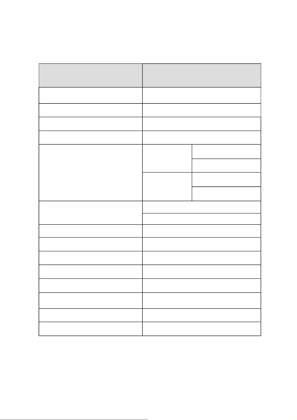
2.2 Technical data
Mode
Parameters
Arc 160-PFC
Power voltage (V) 1 phase AC95V~265V
Frequency (Hz) 50/60
Rated input current (A) 28
No-load voltage(V) 71
Output current adjustment (A) 95-180V
20-110(MMA)
5-110(TIG)
180-265V 20-160(MMA)
5-160(TIG)
Rated Output voltage (V) 20.8-26.4(MMA)
10.2-16.4(TIG)
Duty cycle (%) 20
Power factor More than 0.95
Efficiency (%) More than 84
Insulation grade F
Housing protection grade IP23S
Weight (kg) 6
Welding thickness (mm) More than 0.8
Overall dimension (mm)
351*145*253
9
Page 12

3 Installation
The welding equipment is equipped with power voltage compensation device. It keeps the
machine work normally when power voltage fluctuating at AC95V~AC256V of rated voltage.
When using long cable, in order to reduce voltage drop, big section cable is suggested. If the
cable is too long, it will affect the performance of arcing and other system function, it is
suggested to use the recommend length.
Make sure the intake of the machine is not covered or blocked to avoid the malfunction of
the cooling system.
Use ground cable whose section no less than 6mm2 to connect the housing and earth. The
method is to connect the grounded interface in the back to the earth device, or make sure
the earth end of power interface has been reliably and independently grounded. Both ways
can be used together for better security.
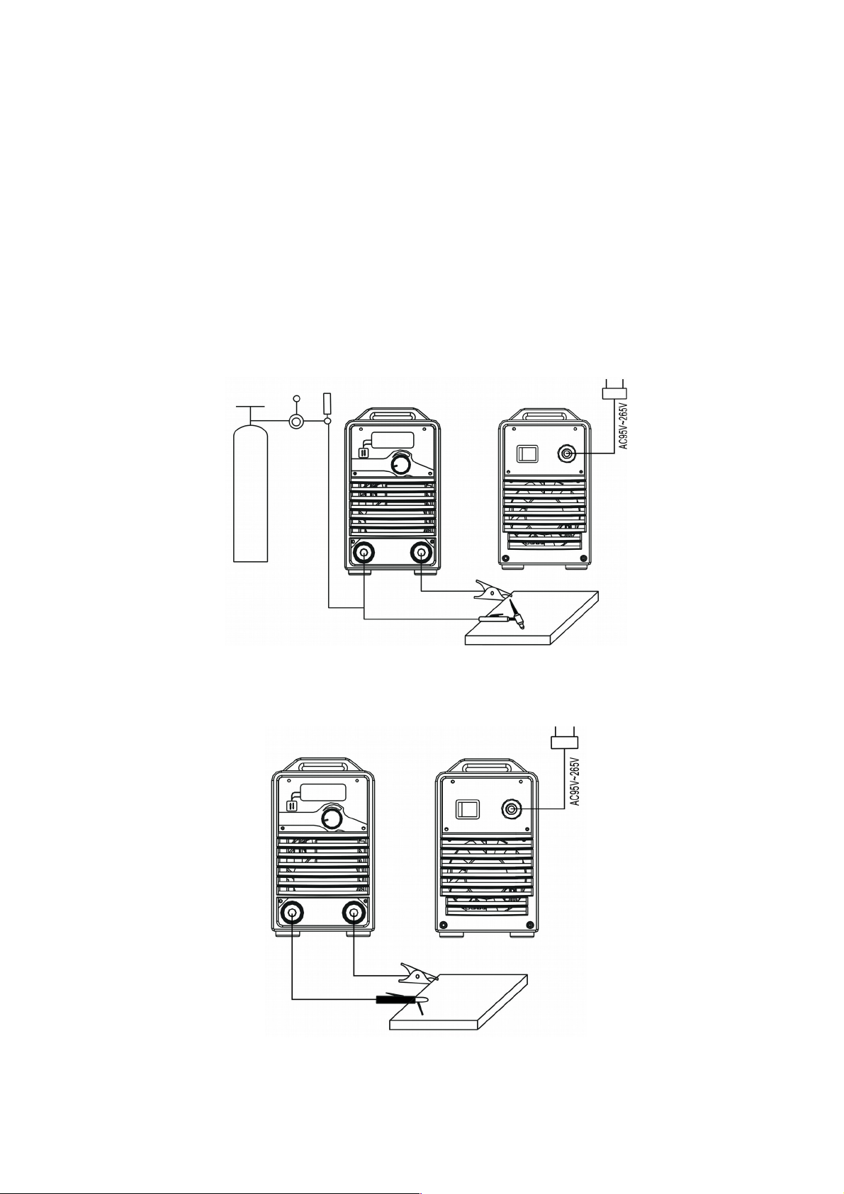
Arc 160-PFC Installation Procedures
:
Correct Installation of LIFT TIG
a) Connect the shielded-gas source correctly. The gas supplying route shall include gas
cylinder, argon decompression flow meter and gas pipe. The connecting parts of the gas
pipe should be fastened by hose clamp or other objects, in order to prevent leakage and air-
in.
b) Connect the plug of TIG torch to “-“of the front panel, and fasten it clockwise.
c) Connect the plug of TIG torch to the relative interfaces of panel and fasten the screw.
d) Connect one end of the earth clamp cable to “+” of the front panel, and fasten it clockwise,
the other end clamp the workpiece.
Correct Installation of STICK
a) Make sure cable with electrode holder and quick plug connected well. Connect the quick
plug to the socket “-” of the machine, and fasten it clockwise tightly.
b) Connect the quick plug at one end of the cable into the socket “+” of the machine, and
fasten it clockwise, the other end clamps the workpiece.
c) Please pay attention to the connecting terminal, DC welding machine has two connecting
ways: positive connection and negative connection. Positive connection: holder connects
with “-” terminal, while work piece with the “+” terminal. Negative connection: work piece with
the“-” terminal, holder with the “+” terminal. Choose suitable way according to the working
situation. If unsuitable choice is made, it will cause unstable arc, more spatters and
conglutination. If such problems occur, please change the polarity of the fastened plug. It
10
Page 13
should adopt negative connection when welding with alkaline electrode, while positive
connection when welding with acid electrode.
This procedure shall be operated by electrician!
Connect proper power cable to the distribution box with corresponding capacity according to
the input voltage and current (See technical parameter table). Do not connect to the
inappropriate voltage and make sure that the difference of power supply is within permitted
range.
Installation drawing of Arc 160-PFC (LIFT TIG)
。
Installation drawing of Arc 160-PFC (STICK)
。
11
Page 14
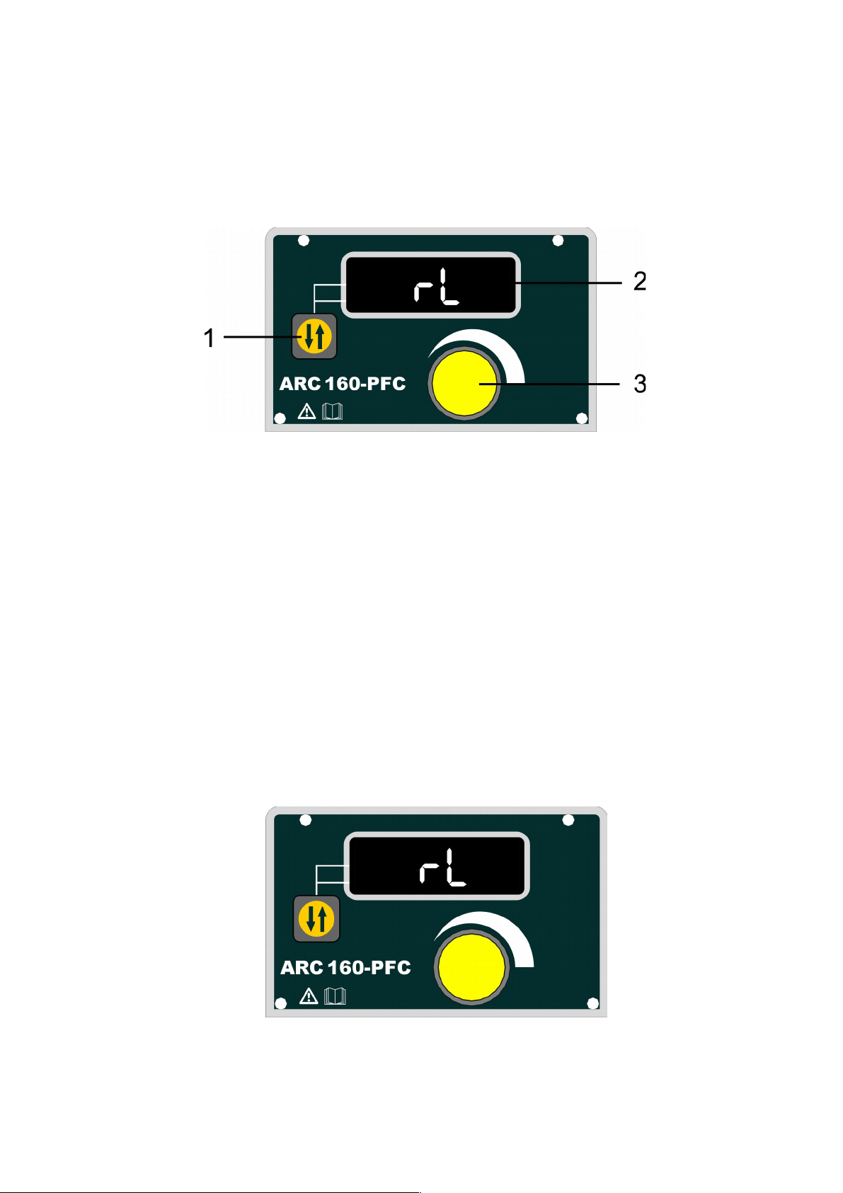
4 Operation
4.1 Front panel layout
1 -STICK/LIFT TIG switch key
2 -Multifunctional data display
3 -Multifunctional data adjusting knob(coarse adjustment by pressing the knob and turning it:
big regulating rate and high speed; fine adjustment only by turning the knob: small
regulating rate and low speed)
4.2 Operation Instruction
The starting up display
Switch on the welding power source, the front panel displays as Chart 1. After
the【Multifunctional data display】(or any key or knob on front panel) flashes for 5 seconds, the
machine enters into the welding mode that saved in the last shutdown.
Chart 1: the starting-up display interface
12
Page 15
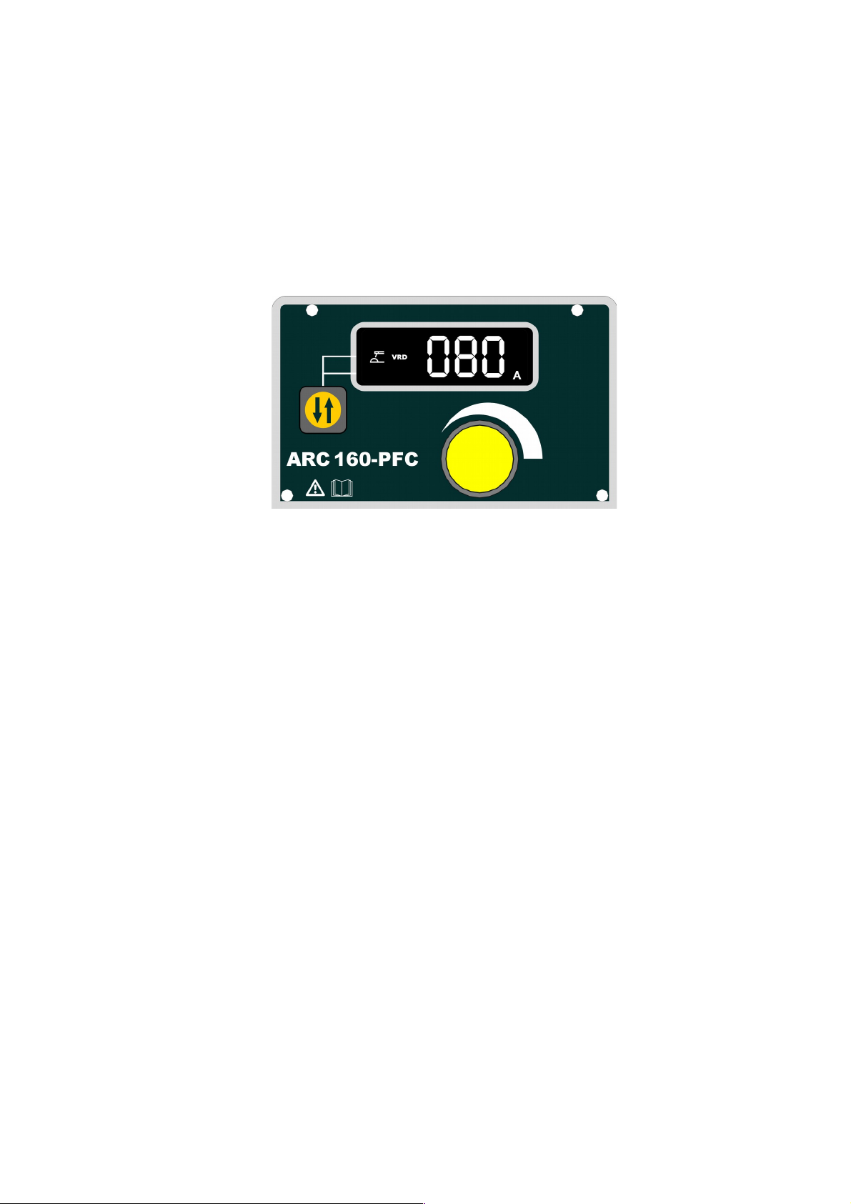
Operation instruction under STICK mode.
a)
When welding stops, Press the【STICK/LIFT TIG switch key
】,
the STICK indicator lights
up,and it turns into STICK mode.
b)
under STICK mode ,Adjusting the 【Multifunctional data adjusting knob】can change the
welding current during welding process, and displayed in 【multifunctional data display】.
【
multifunctional data display】shows the preset current“080A”, its unit is ampere(A).
Chart 2: under STICK mode, preset current display with VRD enabled
c)
5 seconds later after setting the welding parameters, the 【multifunctional data display
】
would flashes for one time, which means the data has been saved. Moreover, the panel
would display these data when restart the machine next time if the parameters keep
unchanged.
d)
When the input voltage is 95V~180V ,then current adjustment range is 20A~110A.And
when the input voltage is 180V~265V ,the current adjustment range is 20A~160A.
Operation instruction under LIFT TIG mode.
a)
When welding stops, press the【STICK/LIFT TIG switch key】,the LIFT TIG indicator lights
up,and it turns into LIFT TIG mode. LIFT TIG means the tungsten contacts the workpiece
first, then the arc is ignited by lifting the torch.
b)
Under LIFT TIG mode, Adjusting the 【Multifunctional data adjusting knob】can change the
welding current during welding process, and displayed in 【multifunctional data display】.
【
multifunctional data display】shows the preset current“080A”, its unit is ampere(A).
13
Page 16
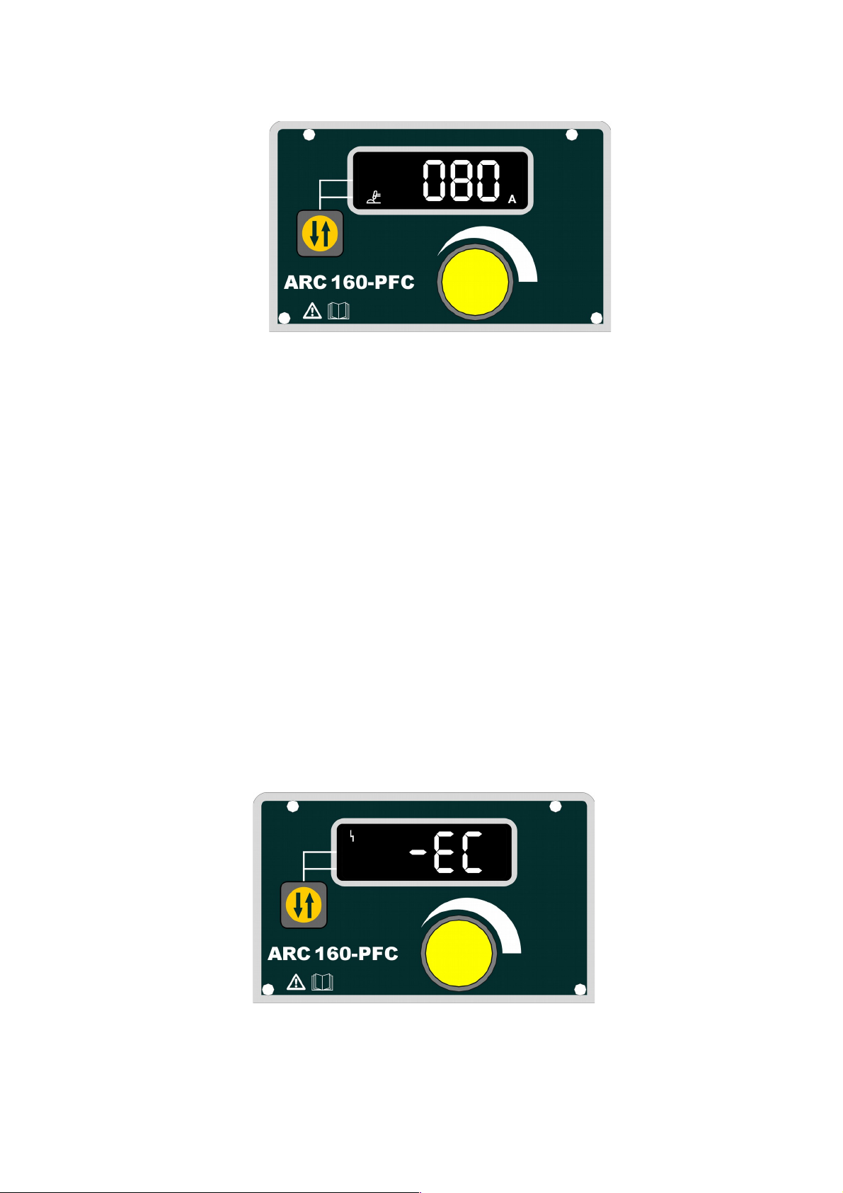
Chart3: The preset current under LIFT TIG mode
c)
5 seconds later after setting the welding parameters, the 【multifunctional data display
】
would flashes for one time, which means the data has been saved. Moreover, the panel
would display these data when restart the machine next time if the parameters keep
unchanged.
d)
When the input voltage is 95V~180V, the current adjustment range is 5A~110A.And when
the input voltage is 180V~265V, the current adjustment range is 5A~160A.
Note:The machine adopts touched ignition way when perform welding under TIG mode.
Firstly make sure the tungsten contacts the workpiece completely, then press the torch
switch, lifting up the torch to ignite arc successfully.
Malfunction display
a) Malfunction display of over-current
The panel displays as Chart 4 when over-current, and the 【multifunctional data display】flashes
continuously, the machine can not work normally. Restart the machine, the panel would display
the parameters that were set before malfunction occurrence.
Chart 4: Malfunction display of over current
14
Page 17
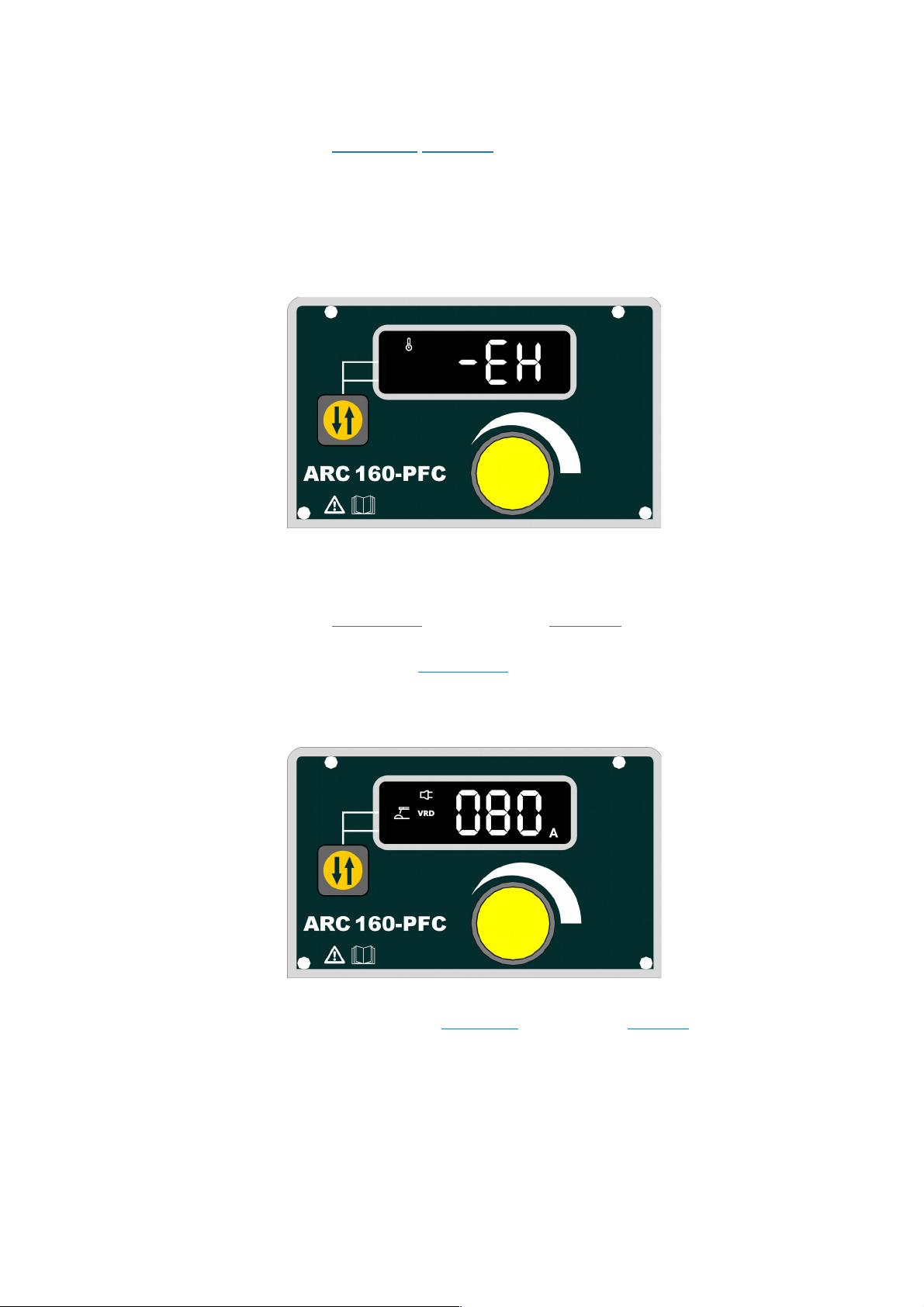
b) Malfunction display of overheating protection
The panel displays as Chart 5 when overheating, and the 【multifunctional data display】flashes
continuously, the machine can not work normally. Only when the temperature of the welding
machine falls below 60 , the overheating malfunction would disappear, and the machine work℃
normally without restarting.
Chart 5:Malfunction display of overheating protection
c) Malfunction display of over-voltage and less-voltage protection
The panel displays as Chart 6 when over-voltage or less-voltage, the 【multifunctional data
display】flashes continuously, the panel would display the parameters as same as before and
the machine can not work normally.
Chart 6:Malfunction display of over-voltage and less-voltage protection
15
Page 18

4.3 Welding environment and safety
Environment
a) The machine works in environment where air conditions are dry with a dampness level of
max 90%.
b) Ambient temperature should be between -10 to 40 degrees centigrade.
c) Avoid welding in sunshine or raining. Avoid water entering the machine
d) Avoid welding in dust area or the environment with corrosive gas.
e) Avoid gas welding in the environment with strong airflow.
Safety Checkpoint
Our welding machine has a protection circuit of over voltage, over current and over heat. When
voltage, output current and temperature of machine are exceeding the rated standard, welding
machine will stop working automatically. Excessive operation under over voltage, over current
or over heat may damage the machine; operator must pay attention to followings.
a) The working area is adequately ventilated
!
The welding machine is medium and small model. But the running of the machine will also
generate high currents, which natural wind circulation cannot satisfy its cooling demands.
Therefore, each machine has an internal fan to ensure its stable performance. Make sure the
intake is not blocked or covered, there should be 0.3 meter distance from welding machine to
objects of environment. User should make sure the working area is adequately ventilated. It is
important for the performance and the longevity of the machine.
b) Do not over load
!
The operator should keep an eye on max duty current (Compared to the selected duty cycle) to
make sure that the machine working current does not exceed max duty cycle current. Over-
load current will damage and even burn the machine.
If machine exceeds standard duty cycle, it may stop working and switch to protection status.
The temperature control switch is activated by over heat released under this circumstance.
Meanwhile, the over heat indicator lights up. Under this situation, you do not need to pull out
the power plug since the internal fan can work to cool down the machine. When the over heat
indicator stops, the temperature has been lowed down to standard range, operator is able to
starting working again.
c) No over voltage
!
Power voltage can be found in diagram of parameters. Automatic compensation circuit of
voltage will assure that welding current keeps is in allowable range. If power voltage is
16
Page 19

exceeding allowable range limits, it can damage the components of machine. The operator
should understand this situation and take preventive measures.
d) There is a grounding cable behind welding machine with a mark. Before operation, welding
crust must be grounded reliably with cable, in order to prevent static electricity, and
accidents for electricity leaking.
4.4 Welding problems and resolution
The phenomenon listed below may happen due to relevant accessories used, welding material,
surroundings and power supply. Pleas improve surroundings and avoid these problems..
Arc starting difficulty. Arc interruption happens easily
a) Examine whether grounding wire clamp contacts with the work pieces well.
b) Examine whether each joint has improper contact.
The output current fails to reach rated value
The deviation of power voltage from rated value may cause that the output current does no
accord with adjusted value. When the power voltage is lower than rated value, the maximum
output current may be lower than rated value.
The current can not keep stable during operation
This situation may relate to the following factors:
a) The voltage of electric power network changes;
b) Serious interference from electric power network or other electric facilities.
Gas vent in welds
a) Examine whether the gas supply circuit has leakage.
b) Examine whether there is sundries such as oil, dirt, rust, paint etc. on the surface.
17
Page 20
5 Daily maintenance and checking
Daily maintenance
a)
Remove dust regularly with dry compressed air. If the welding machine is used in
surroundings with heavy smoke and polluted air, it is necessary to remove dust at least
one time one month.
b)
The pressure of compressed air shall fall to required level to prevent damage to small
components in the machine.
c)
Examine inside electric joints and ensure perfect contact (Especially plugs and sockets).
Fasten the loosing joints. In case of oxidation, remove oxide film with sand paper and
connect again.
d)
Prevent water from entering into the machine and prevent the machine from getting moist.
If any, blow and dry. Measure the insulation with megohmmeter to make sure it is qualified
to use.
e)
If the welding machine is not used for a long time, pack the machine in original package
and store in dry surroundings.
f)
Every time the wire feeder operates for 300hours, grind the electrical carbon brush and
clear up the armature commutator. Rinse speed reducer, apply 2# Molybdenum Disulfide
lubricant to the turbine, whirlpool rod and bearing.
The power shall be cut off completely before all maintenance, repairing works. Make
sure to pull out power plug before opening the case.
18
Page 21
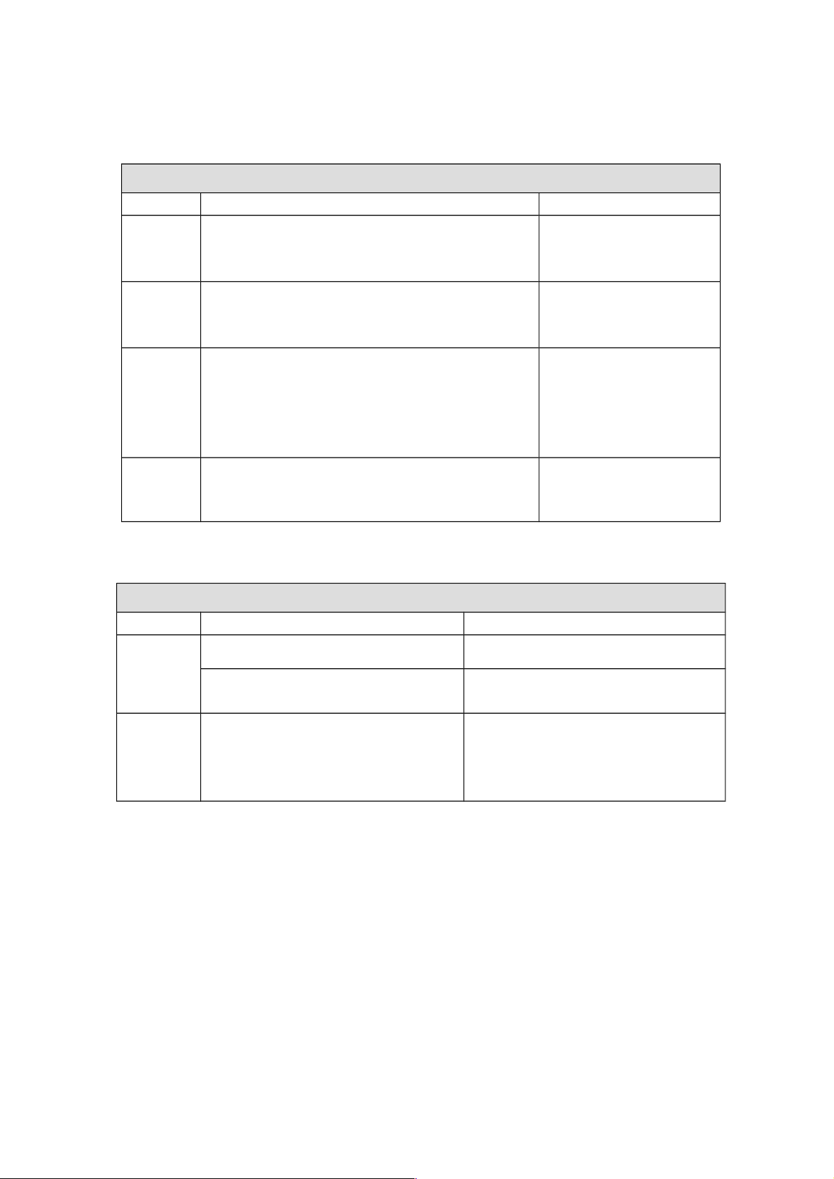
Daily checking
WELDING POWER SUPPLY
Position Check points Remarks
Control
panel
Switch condition of operation, transfer and
installation
Test the power indicator
Cooling
fan
Check if there is wind and the sound normal
or not
If abnormal noise and no
wind, please check the
inner
Power
part
When electrified, abnormal smell or not
When electrified, abnormal vibration and buzz
or not
Color changing and heating or not in
appearance
Periphery Gas pipe broken, loosen or not
Housing and other fixed parts loosen or not
WELDING TORCH
Position Check points Remarks
Nozzle If installation fixed, the front distorted Reason for air hole
Attach splash or not Reason for burning the torch
(can use splash-proof material )
Gas
bypass
Forget to insert or the hole blocked,
or different factory component
May lead to vice (splash) because of
poor gas shield, torch body get
burned (arc in the torch), please
handle
19
Page 22

CABLE
Position Checking keys Remarks
Torch
cable
If torch cable over bended
If the metal connecting point of
mobile plug loosen
Cause poor wire sending
Unstable arc if cable over
bended
Output
cable
Wearing-out of the cable insulated
material
Cable connecting head naked
(insulation damage), or loosen (the
end of power supply, and cable of
main material connecting point)
For life security and stable welding,
adopt suitable method to check
according to working place
Simple check daily
Careful and in-depth check on
fixed period
Input
cable
If the connection between the plug
and the power socket is firm
If the power input end cable fixed
If the input cable is worn out and
bares the conductor
Earth
cable
If the earth cable that connects the
main part is broken and connects
tightly
20
Page 23

6 Trouble shooting and fault finding
Notes: The following operations must be performed by qualified electricians with valid
certifications. Before maintenance, you are suggested to contact local distributor to verify
qualification.
Malfunctions and solutions of Arc 160-PFC.
Malfunctions Solution
The meter show
nothing;
Fan does not rotate;
No welding output
Confirm the power switch is on.
Power supply available for input cable.
Check if the silicon bridge is damaged.
There is malfunction occurs in the supplementary power
source on control board (contact dealers).
The meter shows;
Fan works normally;
No welding output
Check if all the sockets in the machine are connected
well.
There is open circuit or badness of connect at the joint of
output terminal.
The control cable on the torch is broken off or the switch
is damaged.
The control circuit is damaged.(contact to dealers)
the meter shows;
Fan works normally;
Abnormal indicator
lights.
It might be over-current protection, please turn off the
power switch; restart the machine after the abnormal
indicator light winked.
It might be overheating protection, please wait for about
2-3 minutes until the machine renew without turn off the
power switch.
It might be multifunction of inverter circuit. (contact
dealers)
21
Page 24
Even the machine comes up with abnormal phenomenon such as welding unable, arc unstable or
bad welding effect, it is still early to judge that there is malfunction on the machine.
The above-mentioned abnormal phenomenon may be caused by some reasons. For example: tight
parts loosen, forgetting to switch on, wrong set up, cable broken and gas rubber pipe cracked, etc.
Therefore, please test and inspect these factors before deliver it back to the factory because a large
number of troubles may be easily solved probably.
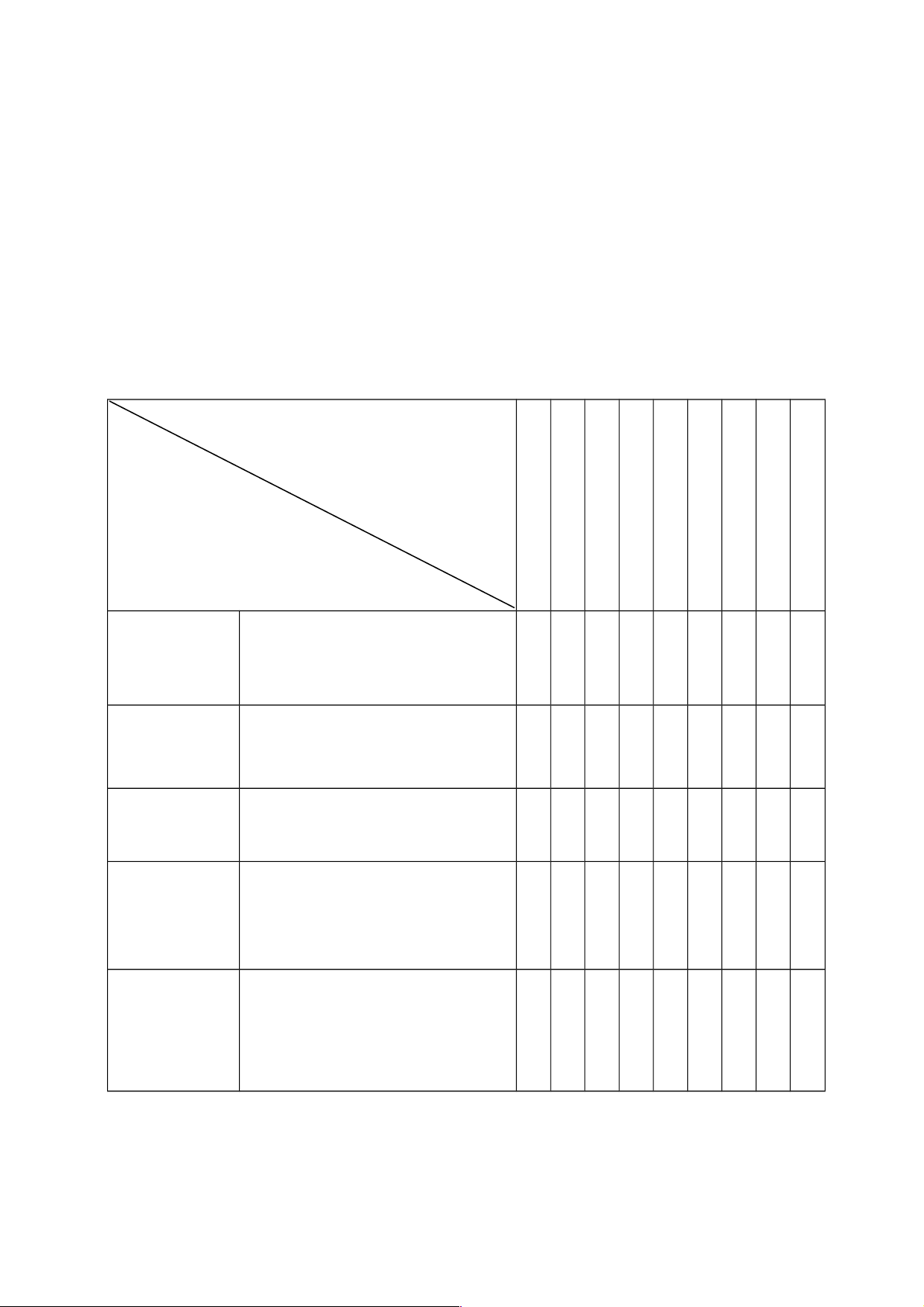
For this reason, an initial diagnosis list for general welding troubles is shown below. A trouble
happened may be found in the column of “Abnormal items” on up-right of the list, please inspect and
maintain for the corresponding items which have “〇" mark in the column according to the following
list respectively.
Initial problems diagnose
Abnormal Items
Area and Item to be Inspected
and Maintained
No arch Arc Starting
No Gas out
No Wire Feeding
Bad Arc Ignition
Unstable Arc
Dirt on Edge of Weld Seam
Wire Stick to Parent material
Wire Stick to Conductive Tip
Blowhole Formed
Distribution Boxes
(Input Protection
Devices)
1. Turn on power supply or not?
2. Fuse burnt out
3. Connection joint loose
〇 〇 〇 〇 〇 〇
Input Cable 1. Examine whether the cable is cut off.
2. Connection joint loose
3. Over heat
〇 〇 〇 〇
Welding Power
Operation
1. Turn on power supply or not?
2. Phase Lacking
〇 〇 〇 〇 〇 〇 〇 〇
Gas Cylinder and
Gas Regulator
1. Turn on gas supply
2. Residual Amount of Gas in the Cylinder
3. Set value for flow
4. Connection joint loose
〇 〇
Gas supply hose
(the whole line
from the high
pressure cylinder
to the weld gun)
1. Connection joint loose
2. Gas hose damaged
〇
22
Page 25
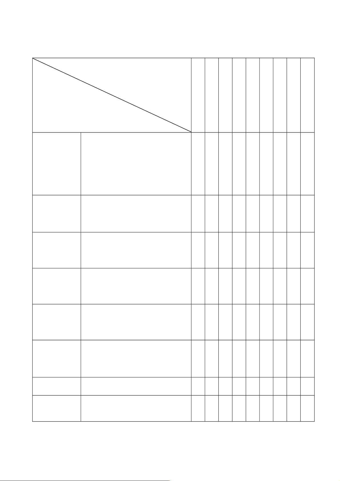
Abnormal Items
Area and Item to be Inspected
and Maintained
No arch
No Gas out
No Wire Feeding
Bad Arc Ignition
Unstable Arc
Dirt on Edge of Weld Sea
Wire Stick to Parent material
Wire Stick to Conductive Tip
Blowhole Formed
Wire Feeding
Device
1. Wire feeding wheel does not match with
the diameter of wire in texturing tube
2. Crackle on wire feeding wheel, groove
blocked up or defect
3. Too tight or loose of the handle
4. Wire powder accumulated on the inlet of
SUS pipe
〇 〇 〇 〇 〇
Weld Gun and
Cable
1. Weld gun cable rolled up or over curved
2. Adaptability of conductive tip, wire feeding
pipe and cable diameter Worn, blocked up or
deformation, etc.
〇 〇 〇 〇
Body of weld gun 1. Loose connection of conductive tip,
nozzle and nozzle contactor
2. Contactor of weld gun body is not
plunged in or tightened well
〇 〇
Power supply
cable of weld gun
as well as cable of
switch control
1. Break off (bending fatigue)
2. Damaged by weighted drop
〇 〇
〇 〇
0
Surface Condition
of Parent material
and length that
wire stretches out
1. Oil, dirty, rust and paint residues
2. Too long length of wire stretched out
〇 〇 〇 〇 〇
Output Cable
1. Cross-section of cable that connects to
parent material is not enough
2. Loose connection of (+),(-)output cable
3. Bad electric conductivity of parent
material
〇 〇 〇
Lengthened Cable 1. Cross-section of cable is not enough
2. It is rolled up or folded
〇 〇 〇 〇
Work Condition
for Welding
Welding current, voltage, angle of weld gun,
welding rate and wire length stretched out
should be confirmed once again
〇 〇 〇 〇 〇
23
Page 26
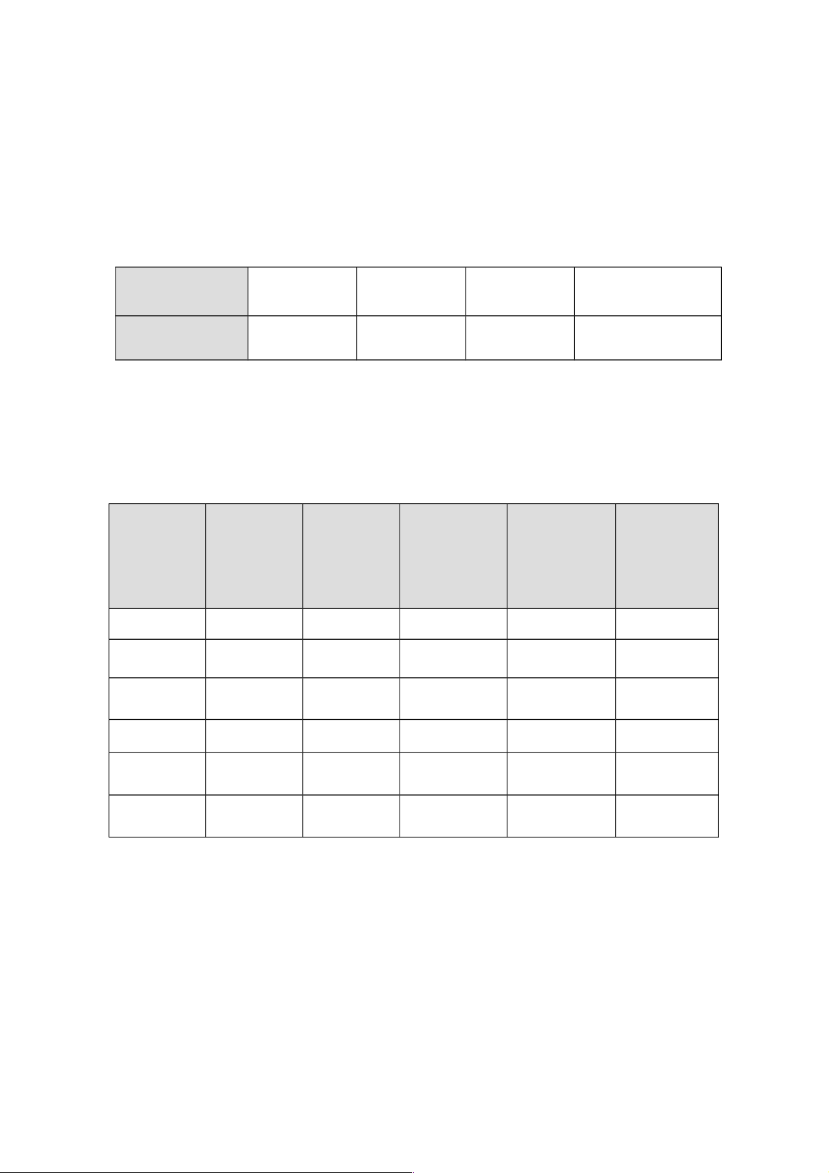
Appendix I Operation parameter recommendation
Generally, welding current is adequate to welding electrode according with as
following:
electrode
specification
φ2.5 φ3.2 φ4.0 φ5.0
welding current 70-100A 110-140A 170-220A 230-280A
Welding variables when use TIG.
TIG welding specifications of stainless steel as follows:
Thickness
(mm)
Tungsten
diameter
(mm)
Wire
diameter
(mm)
Type of butt
joint
Welding
current
(A)
Gas flow
(L/min)
0.5 1.0 1.0 plain butt joint 35-40 4-6
0.8 1.0 1.0 wire filling 35-45 4-6
1.0 1.6 1.6 40-70 5-8
1.5 1.6 1.6 50-85 6-8
2.0 2.0-2.5 2.0 80-130 8-10
3.0 2.5-3.0 2.25 120-150 10-12
24
Page 27
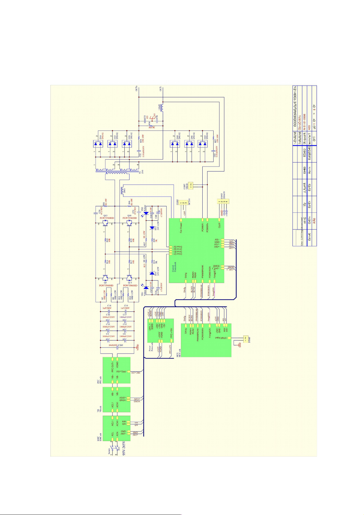
Appendix II Circuit diagram
25
Page 28
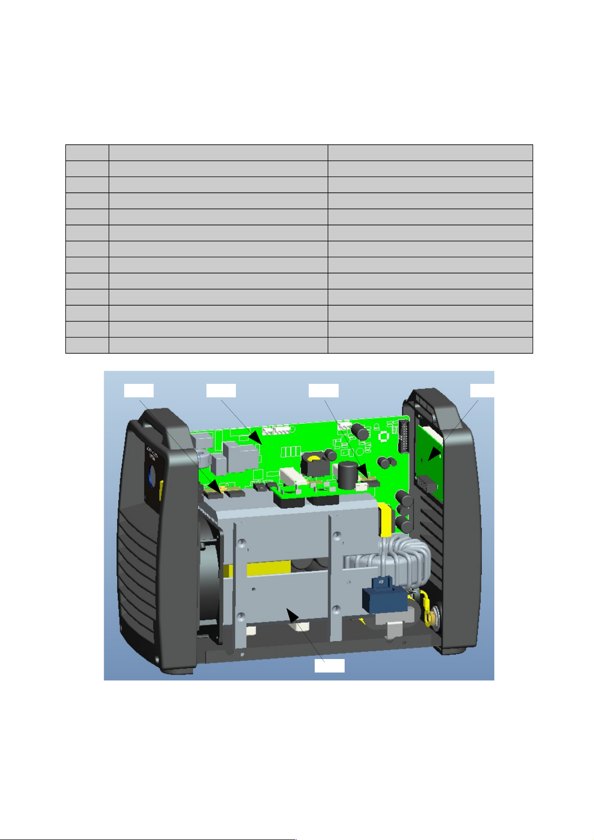
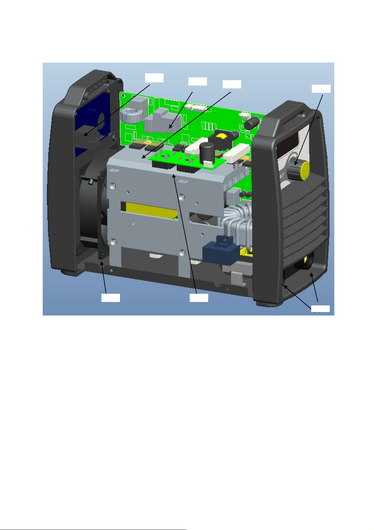
Appendix III Spare parts list
ref TER code
1 I0098AA main board
2 I0099AA display board
3 I0100AA encoder
4 I0101AA thermistor
5 I0102AA rectifier
6 I0103AA diode
7 I0104AA single IGBT
8 I0105AA mosfet
9 E0010AA power switch
10 I0106AA relay
11 I0107AA fan
12 I0108AA fast socket
26
128
7
6
Page 29
27
3
4
10
9
12
5
11
 Loading...