

Suzuki QuadRacer LT-R450 Service Manual
LT-R450
99500-44062-03E
FOREWORD
This manual contains an introductory description on
the SUZUKI LT-R450 and procedures for its inspection, service and overhaul of its main components.
Other information considered as generally known is
not included.
Read the GENERAL INFORMATION section to
familiarize yourself with the vehicle and its maintenance. Use this section as well as other sections as
a guide for proper inspection and service.
This manual will help you know the vehicle better so
that you can assure your customers of fast and reliable service.
GROUP INDEX
GENERAL INFORMATION
PERIODIC MAINTENANCE
ENGINE
1
2
3
* This manual has been prepared on the basis
of the latest specifications at the time of publication. If modifications have been made since
then, differences may exist between the content of this manual and the actual vehicle.
* Illustrations in this manual are used to show
the basic principles of operation and work
procedures. They may not represent the
actual vehicle exactly in detail.
* This manual is written for persons who have
enough knowledge, skills and tools, including
special tools, for servicing SUZUKI vehicles.
If you do not have the proper knowledge and
tools, ask your authorized SUZUKI motorcycle dealer to help you.
Inexperienced mechanics or mechanics
without the proper tools and equipment
may not be able to properly perform the
services described in this manual.
Improper repair may result in injury to the
mechanic and may render the vehicle
unsafe for the rider.
FI SYSTEM DIAGNOSIS
FUEL SYSTEM AND
THROTTLE BODY
COOLING AND
LUBRICATION SYSTEM
CHASSIS
ELECTRICAL SYSTEM
SERVICING INFORMATION
EMISSION CONTROL
INFORMATION
LT-R450K7 (’07-MODEL)
4
5
6
7
8
9
10
11
© COPYRIGHT SUZUKI MOTOR CORPORATION 2005
LT-R450K8 (’08-MODEL)
WIRING DIAGRAM
12
13
HOW TO USE THIS MANUAL
TO LOCATE WHAT YOU ARE LOOKING FOR:
1. The text of this manual is divided into sections.
2. The section titles are listed in the GROUP INDEX.
3. Holding the manual as shown at the right will allow you to find
the first page of the section easily.
4. The contents are listed on the first page of each section to
help you find the item and page you need.
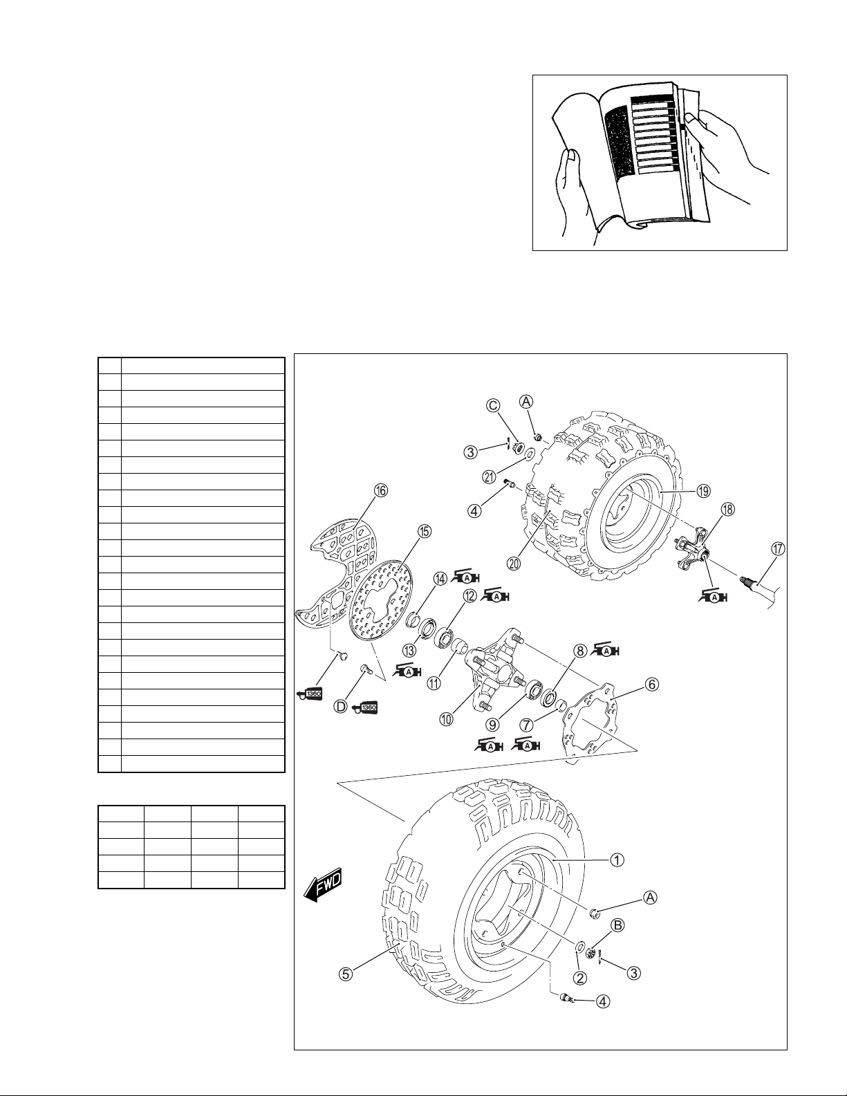
COMPONENT PARTS AND WORK TO BE DONE
Under the name of each system or unit, is its exploded view. Work instructions and other service information
such as the tightening torque, lubricating points and locking agent points, are provided.
Example: Front and rear wheels
1 Front wheel
2 Washer
3 Cotter pin
4 Air valve
5 Front tire
6 Front hub plate
7 Spacer
8 Dust seal
9 Hub bearing
0 Front wheel hub
A Spacer
B Hub bearing
C Dust seal
D Collar
E Front brake disc
F Disc cover
G Axle shaft
H Rear wheel hub
I Rear wheel
J Rear tire
K Washer
A Wheel set nut
B Front hub nut
C Rear hub nut
D Brake disc bolt
"
ITEM N·m
A 66 6.6 47.5
B 65 6.5 47.0
C 121 12.1 87.5
D 23 2.3 16.5
kgf-m
lb-ft
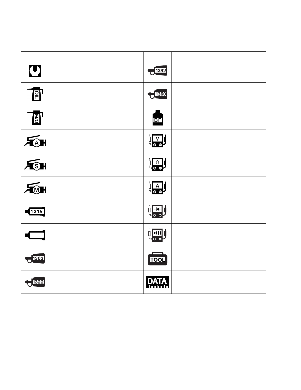
SYMBOL
Listed in the table below are the symbols indicating instructions and other information necessary for servicing. The meaning of each symbol is also included in the table.
SYMBOL DEFINITION SYMBOL DEFINITION
Torque control required.
Data beside it indicates specified
torque.
Apply oil. Use engine oil unless
otherwise specified.
Apply molybdenum oil solution.
(mixture of engine oil and SUZUKl
MOLY PASTE in a ratio of 1 : 1)
Apply SUZUKI SUPER GREASE “A”
or equivalent grease.
99000-25010
Apply SUZUKI SILICONE GREASE.
99000-25100
Apply SUZUKI MOLY PASTE.
99000-25140
Apply SUZUKI BOND “1215”
or equivalent bond.
99000-31110
Apply THREAD LOCK “1342”.
99000-32050
Apply THREAD LOCK SUPER “1360”.
99000-32130
Apply or use brake fluid.
Measure in voltage range.
Measure in resistance range.
Measure in current range.
Measure in diode test range.
1216B
Apply SUZUKI BOND “1216B”.
99000-31230
Apply THREAD LOCK SUPER “1303”.
99000-32030
Apply THREAD LOCK SUPER “1322”
or equivalent thread lock.
99000-32110
Measure in continuity test range.
Use special tool.
Indicates service data.

ABBREVIATIONS USED IN THIS MANUAL
A
ABDC : After Bottom Dead Center
AC : Alternating Current
ACL : Air Cleaner, Air Cleaner Box
API : American Petroleum Institute
ATDC : After Top Dead Center
A/F : Air Fuel Mixture
B
BBDC : Before Bottom Dead Center
BTDC : Before Top Dead Center
B+ : Battery Positive Voltage
C
CKP Sensor : Crankshaft Position Sensor
(CKPS)
CKT : Circuit
CLP Switch : Clutch Lever Position Switch
(Clutch Switch)
CO : Carbon Monoxide
CPU : Central Processing Unit
H
HC : Hydrocarbons
I
IAP Sensor : Intake Air Pressure Sensor (IAPS)
(MAP Sensor)
IAT Sensor : Intake Air Temperature Sensor
(IATS)
IG : Ignition
IAS : Idle air screw
L
LH : Left Hand
M
MAL-Code : Malfunction Code
(Diagnostic Code)
Max : Maximum
MIL : Malfunction Indicator Lamp
Min : Minimum
D
DC : Direct Current
DMC : Dealer Mode Coupler
DOHC : Double Over Head Camshaft
DRL : Daytime Running Light
DTC : Diagnostic Trouble Code
E
ECM : Engine Control Module
Engine Control Unit (ECU)
(FI Control Unit)
ECT Sensor : Engine Coolant Temperature
Sensor (ECTS), Water Temp.
Sensor (WTS)
F
FI : Fuel Injection, Fuel Injector
FP : Fuel Pump
FPR : Fuel Pressure Regulator
FP Relay : Fuel Pump Relay
N
NOX : Nitrogen Oxides
O
OHC : Over Head Camshaft
P
PCV : Positive Crankcase
Ventilation (Crankcase Breather)
R
RH : Right Hand
ROM : Read Only Memory
S
SAE : Society of Automotive Engineers
SDS : Suzuki Diagnosis System
T
TO Sensor : Tip-Over Sensor (TOS)
TP Sensor : Throttle Position Sensor (TPS)
G
GEN : Generator
GND : Ground
GP Switch : Gear Position Switch
SAE-TO-FORMER SUZUKI TERM
This table lists SAE (Society of Automotive Engineers) J1930 terms and abbreviations which may be used in
this manual in compliance with SAE recommendations, as well as their former SUZUKI names.
SAE TERM
FULL TERM ABBREVIATION
A
Air Cleaner ACL Air Cleaner, Air Cleaner Box
B
Battery Positive Voltage B+ Battery Voltage, +B
C
Crankshaft Position Sensor CKP Sensor Crankshaft Position Sensor (CKPS),
Crank Angle
D
Data Link Connector DLC Dealer Mode Coupler
Diagnostic Test Mode DTM ––––
Diagnostic Trouble Code DTC Diagnostic Code, Malfunction Code
E
Electronic Ignition El ––––
Engine Control Module ECM Engine Control Module (ECM)
Fl Control Unit, Engine Control Unit (ECU)
FORMER SUZUKI TERM
Engine Coolant Level ECL Coolant Level
Engine Coolant Temperature ECT Coolant Temperature, Engine Coolant Tem-
perature, Water Temperature
Engine Speed RPM Engine Speed (RPM)
F
Fa n Co n tr o l F C ––––
Fuel Level Sensor –––– Fuel Level Sensor, Fuel Level Gauge
Fuel Pump FP Fuel Pump (FP)
G
Generator GEN Generator
Ground GND Ground (GND, GRD)
I
Ignition Control IC Electronic Spark Advance (ESA)
Ignition Control Module ICM ––––
Intake Air Temperature IAT Intake Air Temperature (IAT), Air Temperature
M
Malfunction Indicator Lamp MIL Lamp
Malfunction Indicator Lamp (MIL)
Manifold Absolute Pressure MAP Intake Air Pressure (IAP), Intake Vacuum

SAE TERM
FORMER SUZUKI TERM
FULL TERM ABBREVIATION
O
On-Board Diagnostic OBD Self-Diagnosis Function
Diagnostic
P
Programmable Read Only Memory PROM ––––
R
Random Access Memory RAM ––––
Read Only Memory ROM ROM
T
Throttle Body TB Throttle Body (TB)
Throttle Body Fuel Injection TBI Throttle Body Fuel Injection (TBI)
Throttle Position Sensor TP Sensor TP Sensor (TPS)
V
Voltage Regulator VR Voltage Regulator

WIRE COLOR
B : Black O : Orange
Bl : Blue P : Pink
Br : Brown R : Red
Dbr : Dark brown W : White
Dg : Dark green Y : Yellow
Gr : Gray
B/Bl : Black with Blue tracer
B/Br : Black with Brown tracer
B/O : Black with Orange tracer
B/R : Black with Red tracer
B/W : Black with White tracer
B/Y : Black with Yellow tracer
Bl/B : Blue with Black tracer
Bl/W : Blue with White tracer
Br/W : Brown with White tracer
G/B : Green with Black tracer
G/R : Green with Red tracer
G/W : Green with White tracer
Gr/W : Gray with White tracer
O/G : Orange with Green tracer
O/W : Orange with White tracer
O/Y : Orange with Yellow tracer
R/W : Red with White tracer
W/B : White with Black tracer
W/Bl : White with Blue tracer
W/R : White with Red tracer
Y/B : Yellow with Black tracer
Y/Bl : Yellow with Blue tracer
GENERAL INFORMATION 1-1
GENERAL INFORMATION
CONTENTS
WARNING/CAUTION/NOTE......................................................................... 1- 2
GENERAL PRECAUTIONS .......................................................................... 1- 2
SUZUKI LT-R450K6 (’06-MODEL)............................................................... 1- 4
SERIAL NUMBER LOCATION ..................................................................... 1- 4
FUEL, OIL AND ENGINE COOLANT RECOMMENDATION....................... 1- 5
FUEL (FOR USA AND CANADA).......................................................... 1- 5
FUEL (FOR OTHER COUNTRIES) ........................................................ 1- 5
ENGINE OIL (FOR USA)........................................................................ 1- 5
ENGINE OIL (FOR OTHER COUNTRIES)............................................. 1- 5
BRAKE FLUID........................................................................................ 1- 5
ENGINE COOLANT................................................................................ 1- 6
BREAK-IN PROCEDURES........................................................................... 1- 6
INFORMATION LABELS .............................................................................. 1- 7
SPECIFICATIONS......................................................................................... 1- 8
DIMENSIONS AND DRY MASS............................................................. 1- 8
ENGINE .................................................................................................. 1- 8
DRIVE TRAIN ......................................................................................... 1- 8
CHASSIS ................................................................................................ 1- 9
ELECTRICAL ......................................................................................... 1- 9
CAPACITIES .......................................................................................... 1- 9
1
COUNTRY AND AREA CODES
The following codes stand for the applicable country(-ies) and area(-s).
CODE COUNTRY or AREA EFFECTIVE FRAME NO.
E-19
E-28
E-33
E.U.
Canada
California (U.S.A.)
JSAAL41A 62100001 –
JSAAL41A 62100001 –
JSAAL41A 62100001 –

1-2 GENERAL INFORMATION
WARNING/CAUTION/NOTE
Please read this manual and follow its instructions carefully. To emphasize special information, the symbol
and the words WARNING, CAUTION and NOTE have special meanings. Pay special attention to the messages highlighted by these signal words.
!
Indicates a potential hazard that could result in death or injury.
#
Indicates a potential hazard that could result in vehicle damage.
NOTE:
Indicates special information to make maintenance easier or instructions clearer.
Please note, however, that the warnings and cautions contained in this manual cannot possibly cover all
potential hazards relating to the servicing, or lack of servicing, of the vehicle. In addition to the WARNINGS
and CAUTIONS stated, you must use good judgement and basic mechanical safety principles. If you are
unsure about how to perform a particular service operation, ask a more experienced mechanic for advice.
GENERAL PRECAUTIONS
!
* Proper service and repair procedures are important for the safety of the service mechanic and
the safety and reliability of the vehicle.
* When 2 or more persons work together, pay attention to the safety of each other.
* When it is necessary to run the engine indoors, make sure that exhaust gas is forced out-
doors.
* When working with toxic or flammable materials, make sure that the area you work in is well-
ventilated and that you follow all of the material manufacturer’s instructions.
* Never use gasoline as a cleaning solvent.
* To avoid getting burned, do not touch the engine, engine oil, radiator and exhaust system
until they have cooled.
After servicing the fuel, oil, water, exhaust or brake systems, check all lines and fittings related
to the system for leaks.

GENERAL INFORMATION 1-3
#
* If parts replacement is necessary, replace the parts with Suzuki Genuine Parts or their equiva-
lent.
* When removing parts that are to be reused, keep them arranged in an orderly manner so that
they may be reinstalled in the proper order and orientation.
* Be sure to use special tools when instructed.
* Make sure that all parts used in reassembly are clean. Lubricate them when specified.
* Use the specified lubricant, bond, or sealant.
* When removing the battery, disconnect the negative cable first and then the positive cable.
* When reconnecting the battery, connect the positive cable first and then the negative cable,
and replace the terminal cover on the positive terminal.
* When performing service to electrical parts, if the service procedures do not require use of
battery power, disconnect the negative cable from the battery.
* When tightening the cylinder head or case bolts and nuts, tighten the larger sizes first.
Always tighten the bolts and nuts diagonally from the inside toward outside and to the speci-
fied tightening torque.
* Whenever you remove oil seals, gaskets, packing, O-rings, locking washers, self-locking
nuts, cotter pins, circlips and certain other parts as specified, be sure to replace them with
new ones. Also, before installing these new parts, be sure to remove any left over material
from the mating surfaces.
* Never reuse a circlip. When installing a new circlip, take care not to expand the end gap larger
than required to slip the circlip over the shaft. After installing a circlip, always ensure that it is
completely seated in its groove and securely fitted.
* Use a torque wrench to tighten fasteners to the specified torque. Wipe off grease and oil if a
thread is smeared with them.
* After reassembling, check parts for tightness and proper operation.
* To protect the environment, do not unlawfully dispose of used motor oil, engine coolant and
other fluids: batteries and tires.
* To protect Earth’s natural resources, properly dispose of used vehicle and parts.
1-4 GENERAL INFORMATION
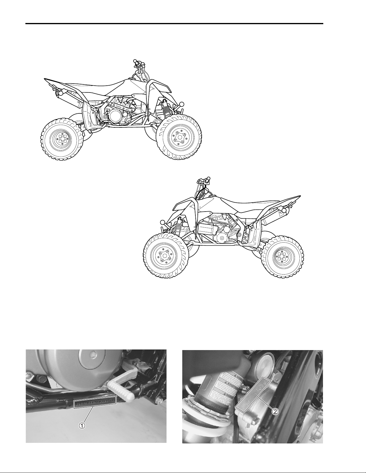
SUZUKI LT-R450K6 (’06-MODEL)
RIGHT SIDE
LEFT SIDE
• Difference between photograph and actual vehicle may exist depending on the markets.
SERIAL NUMBER LOCATION
The frame serial number or V.I.N. (Vehicle Identification Number)
steering head pipe. The engine serial number
bers are required especially for registering the machine and ordering spare parts.
2 is located on the rear side of the crankcase. These num-
1 is stamped on the right side of the
GENERAL INFORMATION 1-5
FUEL, OIL AND ENGINE COOLANT RECOMMENDATION
FUEL (FOR USA AND CANADA)
Use only unleaded gasoline of at least 90 pump octane (R/2 + M/2).
Gasoline containing MTBE (Methyl Tertiary Butyl Ether), less than 10% ethanol, or less than 5% methanol
with appropriate cosolvents and corrosion inhibitor is permissible.
FUEL (FOR OTHER COUNTRIES)
Gasoline used should be graded 95 octane (Research Method) or higher. Unleaded gasoline is recommended.
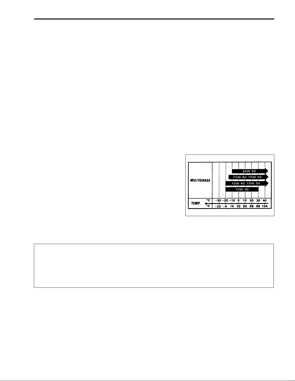
ENGINE OIL (FOR USA)
Oil quality is a major contributor to your engine’s performance and life. Always select good quality engine oil.
Suzuki recommends the use of SUZUKI PERFORMANCE 4 MOTOR OIL or equivalent engine oil. Use of
SF/SG or SH/SJ in API with MA in JASO.
Suzuki recommends the use of SAE 10W-40 engine oil. If SAE 10W-40 engine oil is not available, select an
alternative according to the following chart.
ENGINE OIL (FOR OTHER COUNTRIES)
Oil quality is a major contributor to your engine’s performance
and life. Always select good quality engine oil. Use of SF/SG or
SH/SJ in API with MA in JASO.
Suzuki recommends the use of SAE 10W-40 engine oil. If SAE
10W-40 engine oil is not available, select an alternative according to the right chart.
BRAKE FLUID
Specification and classification: DOT 4
!
Since the brake system of this vehicle is filled with a glycol-based brake fluid by the manufacturer, do not use or mix different types of fluid such as silicone-based and petroleum-based
fluid for refilling the system, otherwise serious damage will result.
Do not use any brake fluid taken from old or used or unsealed containers.
Never re-use brake fluid left over from a previous servicing, which has been stored for a long
period.
1-6 GENERAL INFORMATION
ENGINE COOLANT
Use an anti-freeze/engine coolant compatible with an aluminum radiator, mixed with distilled water only.
WATER FOR MIXING
Use distilled water only. Water other than distilled water can corrode and clog the aluminum radiator.
ANTI-FREEZE/ENGINE COOLANT
The engine coolant performs as a corrosion and rust inhibitor as well as anti-freeze. Therefore, the engine
coolant should be used at all times even though the atmospheric temperature in your area does not go down
to freezing point.
Suzuki recommends the use of SUZUKI COOLANT anti-freeze/engine coolant. If this is not available, use
an equivalent which is compatible with an aluminum radiator.
LIQUID AMOUNT OF WATER/ENGINE COOLANT
Solution capacity (total): Approx. 1 400 ml (1.5/1.2 US/Imp qt)
For engine coolant mixture information, refer to cooling system section in page 6-2.
#
Mixing of anti-freeze/engine coolant should be limited to 60%. Mixing beyond it would reduce
its efficiency. If the anti-freeze/engine coolant mixing ratio is below 50%, rust inhabiting performance is greatly reduced. Be sure to mix it above 50% even though the atmospheric temperature does not go down to the freezing point.
BREAK-IN PROCEDURES
During manufacture only the best possible materials are used and all machined parts are finished to a very
high standard but it is still necessary to allow the moving parts to “BREAK-IN” before subjecting the engine
to maximum stresses. The future performance and reliability of the engine depends on the care and restraint
exercised during its early life. The general rules are as follows.
• Keep to these break-in engine speed limits:
Break-in engine speeds
Initial 10 hours: Less than ½ throttle
• After the engine has been operated for 10 hours the engine to full throttle operation, for short periods of
time.
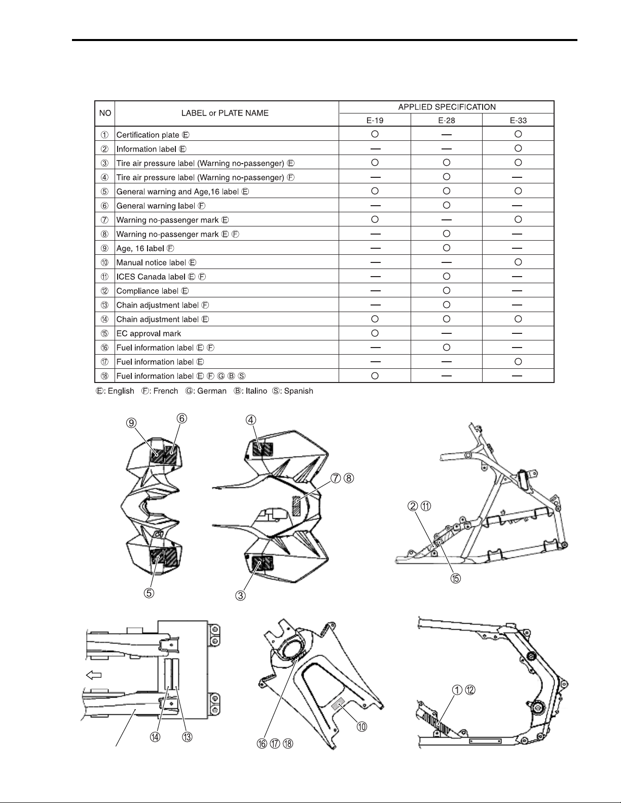
INFORMATION LABELS
GENERAL INFORMATION 1-7
Front
Swingarm
Upper surface
of seat
Right side of frame
Left side of frame
Upper surface
of fuel tank cover

1-8 GENERAL INFORMATION
SPECIFICATIONS
DIMENSIONS AND DRY MASS
Overall length....................................................... 1 845 mm (72.6 in)
Overall width ........................................................ 1 245 mm (49.0 in)
Overall height....................................................... 1 085 mm (42.7 in)
Wheelbase ........................................................... 1 285 mm (50.6 in)
Front track ............................................................ 1 045 mm (41.1 in)
Rear track ............................................................ 985 mm (38.8 in)
Ground clearance ................................................ 240 mm (9.4 in)
Seat height ........................................................... 780 mm (30.7 in)
Dry mass .............................................................. 167 kg (368 lbs)
ENGINE
Type ..................................................................... Four stroke, liquid-cooled, DOHC
Number of cylinders ............................................. 1
Bore ..................................................................... 95.5 mm (3.760 in)
Stroke................................................................... 62.8 mm (2.472 in)
Displacement ....................................................... 450 cm³ (27.5 cu. in)
Compression ratio................................................ 11.7 : 1
Fuel system.......................................................... Fuel injection
Air cleaner............................................................ Polyurethane foam element
Starter system...................................................... Electric
Lubrication system............................................... Dry sump
Idle speed ............................................................ 1 800 ± 100 r/min
DRIVE TRAIN
Clutch................................................................... Wet multi-plate type
Transmission........................................................ 5-forward
Gearshift pattern .................................................. 1 down 4 up, foot operated
Primary reduction ratio......................................... 2.851 (77/27)
Gear ratios, Low ................................................. 2.076 (27/13)
2nd.................................................. 1.647 (28/17)
3rd .................................................. 1.333 (28/21)
4th................................................... 1.095 (23/21)
Top ................................................. 0.913 (21/23)
Final reduction ratio ............................................. 2.571 (36/14)
Drive chain ........................................................... RK 520SMOZ10S, 96 Links

GENERAL INFORMATION 1-9
CHASSIS
Front suspension................................................. Independent, double wishbone, coil spring, oil damped
Rear suspension ................................................. Swingarm type, coil spring, oil damped
Front wheel travel................................................ 254 mm (10.0 in)
Rear wheel travel ................................................ 277 mm (10.9 in)
Caster.................................................................. 8.0°
Trail ..................................................................... 30 mm (1.18 in)
Toe-in .................................................................. 0 mm
Camber ............................................................... –3.0°
Steering angle ..................................................... 41°
Turning radius ..................................................... 3.5 m (11.5 ft)
Front brake.......................................................... Disc brake, twin
Rear brake .......................................................... Disc brake
Front tire size ...................................................... AT20 × 7 R10$$$, tubeless
Rear tire size ....................................................... AT18 × 10 R8$$$, tubeless
ELECTRICAL
lgnition type ......................................................... Electronic ignition (Transistorized)
lgnition timing ...................................................... 8° B.T.D.C. at 1 800 r/min
Spark plug ........................................................... NGK CR8EB
Battery ................................................................. 12 V 21.6 kC (6 Ah)/10 HR
Generator ............................................................ Three-phase A.C. generator
Main fuse............................................................. 20 A
Fan fuse .............................................................. 10 A
Ignition fuse......................................................... 10 A
Headlight ............................................................. 12 V 40/40 W
Brake light/Taillight .............................................. LED
Neutral indicator light .......................................... 12 V 3.4 W
Fuel indicator light ............................................... 12 V 3.4 W
Coolant tempereture/
Fuel injection warning light................................... 12 V 3.4 W
CAPACITIES
Fuel tank, including reserve ................................ 10.0 L (2.6/2.2 US/lmp gal)
Engine oil, oil change ......................................... Oil tank 1 200 ml (1.3/1.1 US/Imp qt)
Engine 400 ml (0.4/0.4 US/Imp qt)
with filter change............................... Oil tank 1 300 ml (1.4/1.1 US/lmp qt)
Engine 400 ml (0.4/0.4 US/lmp qt)
overhaul ............................................ Oil tank 1 400 ml (1.5/1.2 US/lmp qt)
Engine 400 ml (0.4/0.4 US/lmp qt)
Coolant ................................................................ 1.4 L (1.5/1.2 US/lmp qt)
These specifications are subject to change without notice.

PERIODIC MAINTENANCE 2-1
PERIODIC MAINTENANCE
CONTENTS
PERIODIC MAINTENANCE SCHEDULE ........................................... 2- 2
PERIODIC MAINTENANCE CHART .......................................... 2- 2
MAINTENANCE AND TUNE-UP PROCEDURES .............................. 2- 3
AIR CLEANER ............................................................................ 2- 3
EXHAUST PIPE NUTS AND MUFFLER BOLTS ....................... 2- 4
VALVE CLEARANCE ................................................................. 2- 5
SPARK PLUG ............................................................................. 2-10
FUEL LINE .................................................................................. 2-11
FUEL FILTER .............................................................................. 2-11
THROTTLE CABLE PLAY .......................................................... 2-11
ENGINE IDLE SPEED ................................................................. 2-12
THROTTLE BODY ...................................................................... 2-12
ENGINE OIL AND OIL FILTER ................................................... 2-12
ENGINE OIL HOSE ..................................................................... 2-14
ENGINE COOLANT .................................................................... 2-15
RADIATOR .................................................................................. 2-16
RADIATOR HOSE ....................................................................... 2-16
SPARK ARRESTER ................................................................... 2-17
CLUTCH CABLE PLAY .............................................................. 2-18
BRAKES ...................................................................................... 2-18
BRAKE FLUID ............................................................................ 2-21
BRAKE HOSE ............................................................................. 2-23
TIRES .......................................................................................... 2-23
STEERING .................................................................................. 2-24
DRIVE CHAIN ............................................................................. 2-25
SUSPENSIONS ........................................................................... 2-28
FRONT AND REAR WHEEL SET NUTS .................................... 2-28
REAR AXLE NUT AND LOCK-NUT ........................................... 2-29
CHASSIS BOLTS AND NUTS .................................................... 2-30
GENERAL LUBRICATION ......................................................... 2-33
2
6
COMPRESSION PRESSURE CHECK ................................................ 2-34
COMPRESSION TEST PROCEDURE ........................................ 2-34
OIL PRESSURE CHECK ..................................................................... 2-35
OIL PRESSURE TEST PROCEDURE ........................................ 2-35
SDS CHECK ........................................................................................ 2-36
2-2 PERIODIC MAINTENANCE
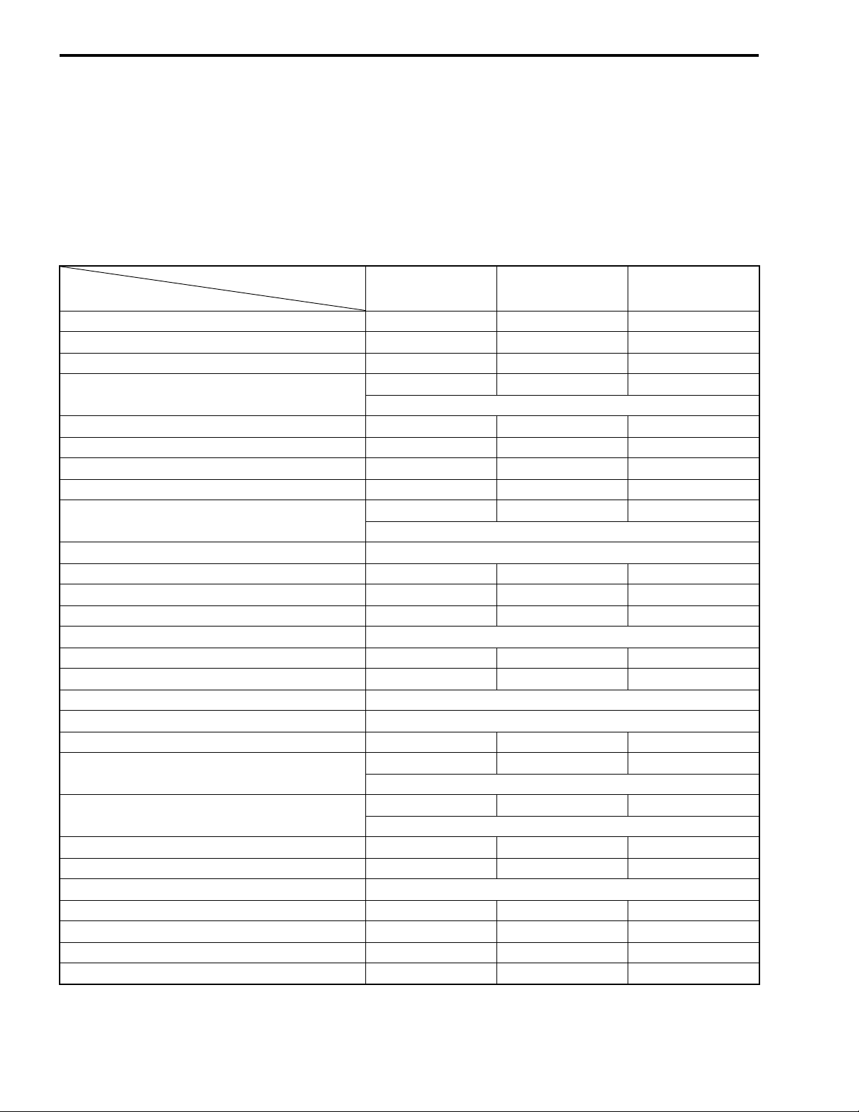
PERIODIC MAINTENANCE SCHEDULE
The chart below lists the recommended intervals for all the required periodic service work necessary to keep
the vehicle operating at peak performance and economy. Maintenance intervals are expressed in terms of
months.
NOTE:
More frequent servicing may be performed on vehicles that are use under severe conditions.
PERIODIC MAINTENANCE CHART
Interval
Item
Air cleaner element — C C
Exhaust pipe nuts and muffler bolts T T T
Valve clearance I — I
Spark plug
Spark arrester — — C
Idle speed I I I
Throttle cable play I I I
Throttle body — I I
Fuel line
Fuel filter Replace every 4 years.
Engine oil and oil filter R — R
Engine oil hose I I I
Clutch cable play I I I
Engine coolant Replace every 2 years.
Radiator — I I
Radiator hose — — I
Drive chain Clean, lubricate and inspect each time the vehicle is ridden.
Drive chain buffer Inspect each time the vehicle is ridden.
Brakes III
Brakes fluid
Brake hose
Tires — I I
Suspensions — — I
Front and rear wheel set nuts Tighten each time the vehicle is ridden.
Rear axle nut and lock-nut T T T
Steering III
Chassis bolts and nuts T T T
General lubrications L L L
NOTE:
I = Inspect and adjust, clean, lubricate, or replace as necessary.
R = Replace C = Clean
T = Tighten L = Lubricate
Initial Every
1 month 3 months 6 months
—— I
Replace every 18 months.
—I I
Replace every 4 years.
—I I
Replace every 2 years.
—— I
Replace every 4 years.
Every
PERIODIC MAINTENANCE 2-3
MAINTENANCE AND TUNE-UP PROCEDURES
This section describes the servicing procedures for each item
mentioned in the Periodic Maintenance chart.
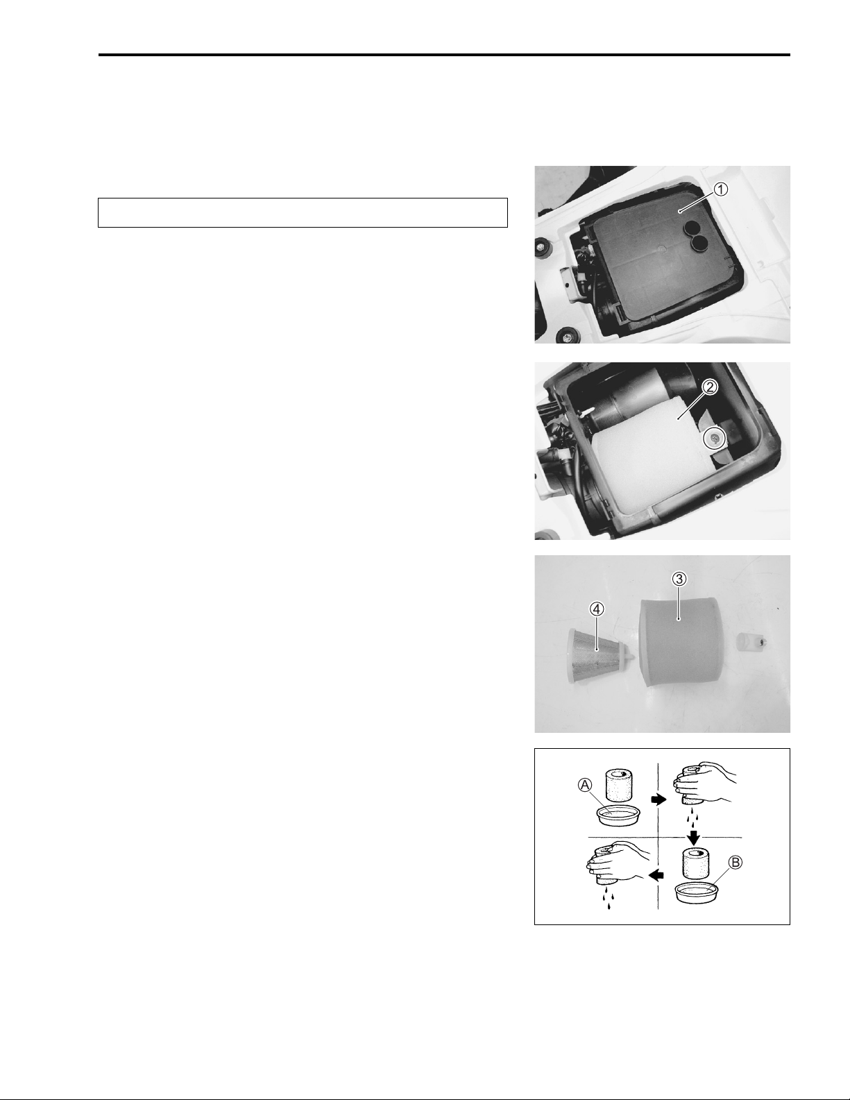
AIR CLEANER
Clean every 3 months.
If the air cleaner is clogged with dust, intake resistance will be
increased, with a resultant decrease in power output and an
increase in fuel consumption. Check and clean the air cleaner
element in the following manner.
• Remove the seat. (%7-6)
• Remove the air cleaner case cover
1.
• Remove the air cleaner element
• Separate the polyurethane foam element
4 and element holder.
• Fill a wash pan of a proper size with a non-flammable cleaning solvent. Immerse the air cleaner element in the cleaning
solvent and wash it.
• Press the air cleaner element between the palms of both
hands to remove the excess solvent: do not twist or wring the
element or it will tear.
• Immerse the element in motor oil, and then squeeze out the
excess oil leaving the element slightly wet.
A Non-flammable cleaning solvent
B MOTUL AIR FILTER OIL or equivalent filter oil
2.
3, element frame
2-4 PERIODIC MAINTENANCE
#
* Inspect the air cleaner element for tears. A torn ele-
ment must be replaced.
* If driving under dusty conditions, clean the air
cleaner element more frequently. The surest way to
accelerate engine wear is to operate the engine without the element or with torn element. Make sure that
the air cleaner element is in good condition at all
times. Life of the engine depends largely on this
component!
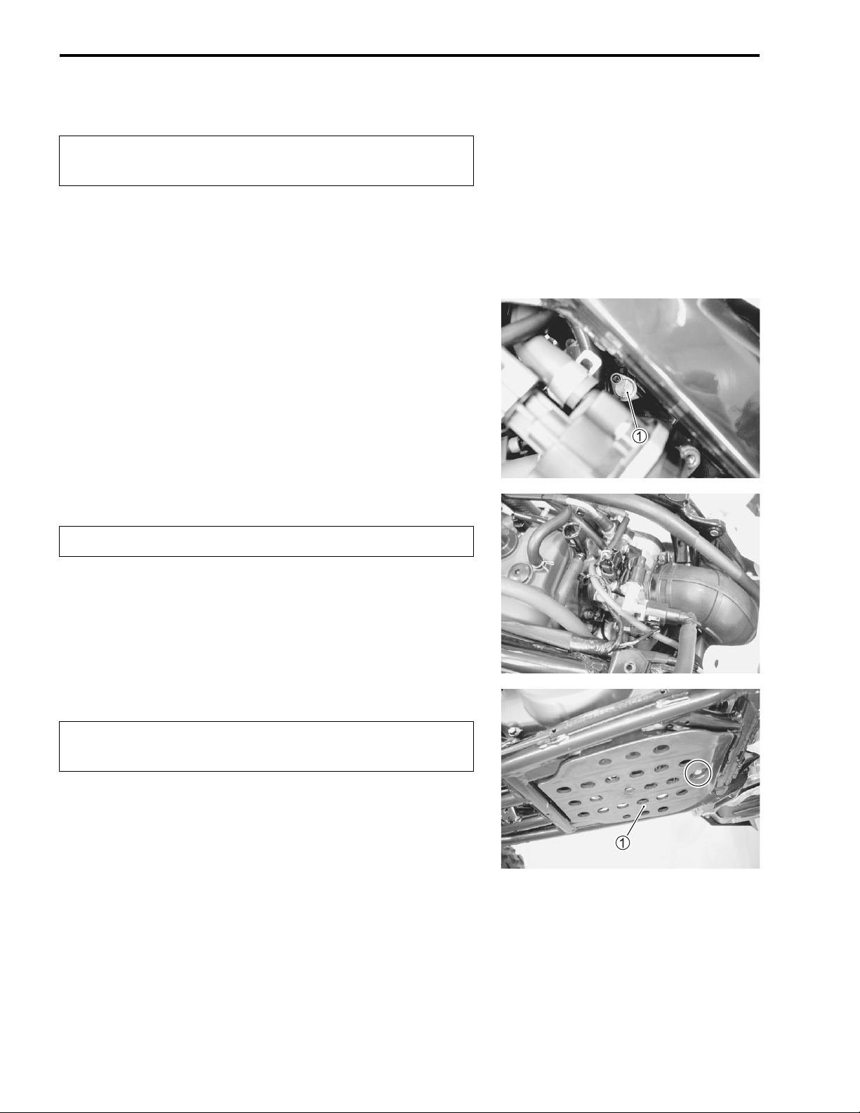
• Remove the drain cap
water to drain out.
5 of the air cleaner box to allow any
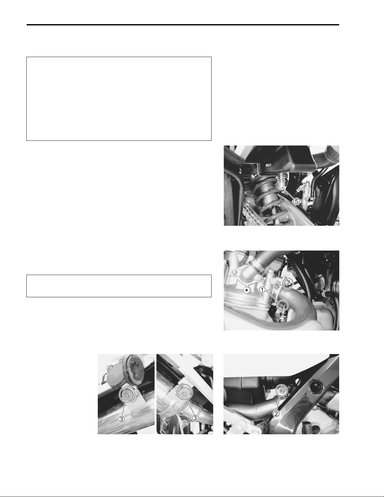
EXHAUST PIPE NUTS AND MUFFLER
BOLTS
Tighten initially at 1 month and every 3 months thereafter.
• Tighten the exhaust pipe nuts
and muffler mounting bolt
" Exhaust pipe nut: 23 N·m (2.3 kgf-m, 16.5 lb-ft)
Muffler connection bolt: 23 N·m (2.3 kgf-m, 16.5 lb-ft)
Muffler mounting bolt: 23 N·m (2.3 kgf-m, 16.5 lb-ft)
1, muffler connection bolt 2,
3 to the specified torque.
PERIODIC MAINTENANCE 2-5
VALVE CLEARANCE
Inspect initially at 1 month and every 6 months thereafter.
Excessive valve clearance results in valve noise and insufficient
valve clearance results in valve damage and reduced power.
Check the intake and exhaust valve clearances at the distances
indicated above and adjust the valve clearances to specification,
if necessary.
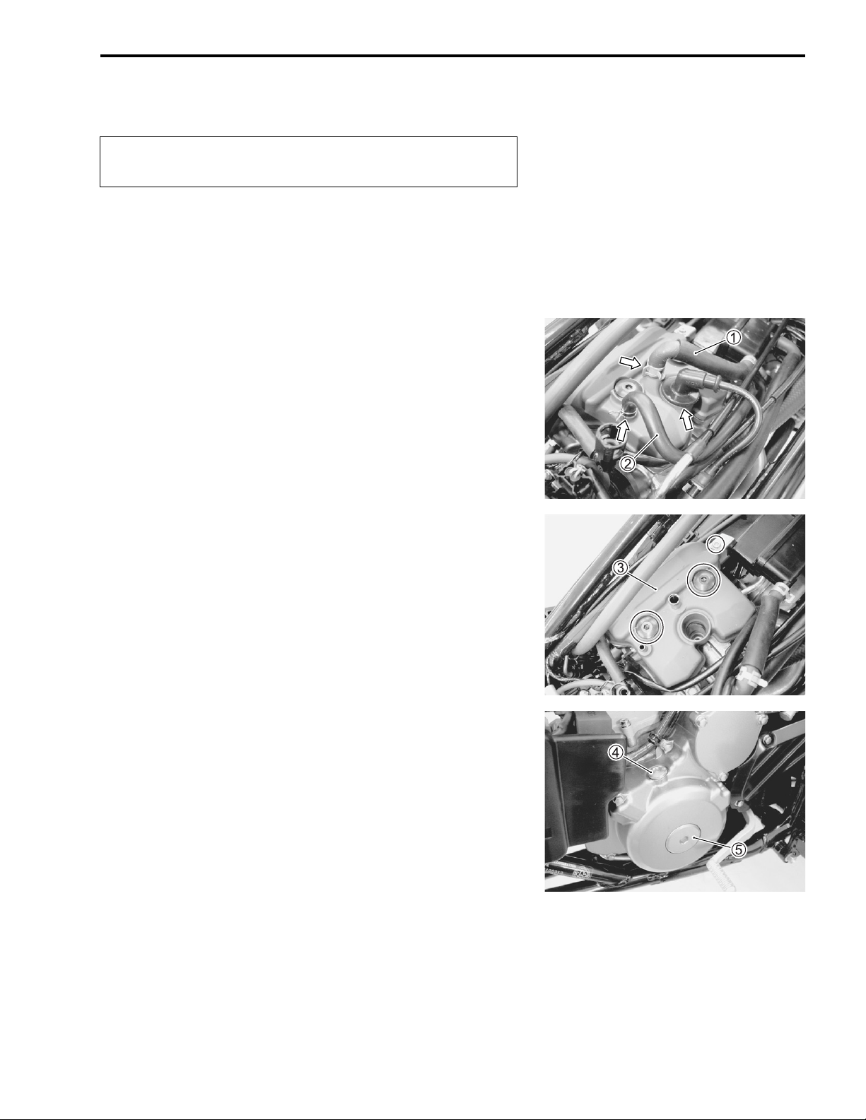
• Remove the seat. (%7-6)
• Remove the side covers, fuel tank cover and front fender.
(%7-6)
• Remove the fuel tank and fuel tank lower cover. (%5-4)
• Remove the spark plug cap and spark plug. (%2-10)
• Disconnect the breather hose
1 and oil tank over-flow hose 2.
• Remove the cylinder head cover
The valve clearance specification is different for intake and
exhaust valves.
Valve clearance must be checked and adjusted, 1) at the time of
periodic inspection, 2) when the valve mechanism is serviced,
and 3) when the camshafts are removed for servicing.
• Remove the valve timing inspection plug
cover cap
NOTE:
* The piston must be at top dead center (TDC) on the compres-
sion stroke in order to check or adjust the tappet clearance.
* The tappet clearance should only be checked when the engine
is cold.
5.
3.
4 and generator
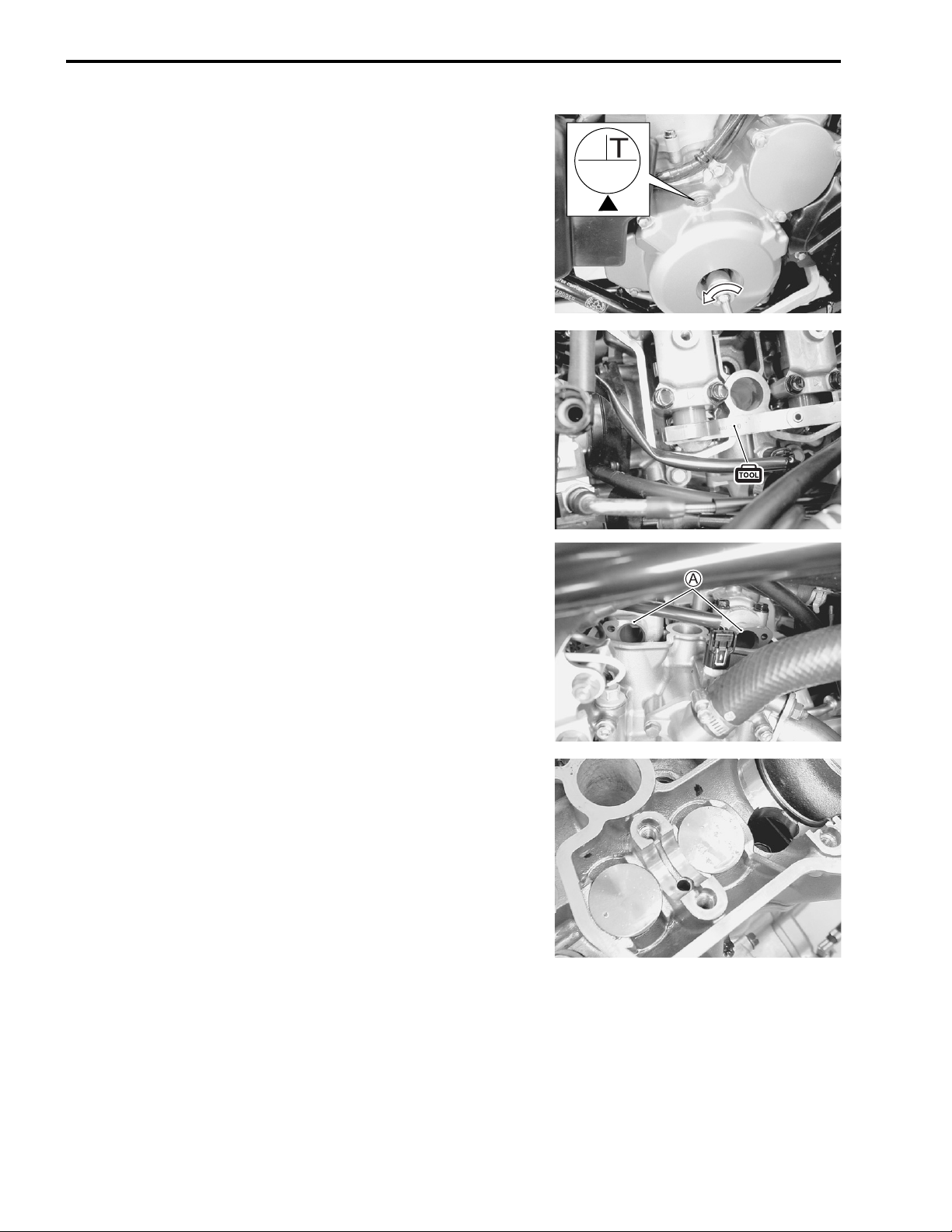
2-6 PERIODIC MAINTENANCE
• Rotate the crankshaft with a box wrench to set the piston at
TDC on the compression stroke. (Rotate the crankshaft until
the “T” line on the generator rotor is aligned with the triangle
mark on the generator cover.)
• Insert a thickness gauge between the tappet and the cam. If
the clearance is out of specification, adjust it to the specification as follows.
& 09900-20803: Thickness gauge
' Valve clearance (when cold)
IN: 0.10 – 0.20 mm (0.0039 – 0.0079 in)
EX: 0.20 – 0.30 mm (0.0079– 0.0118 in)
NOTE:
The cam must be at position
A, when checking and adjusting
the valve clearance. Clearance readings should not be taken
with the cam in any other position than this position.
ADJUSTMENT
The clearance is adjusted by replacing the existing tappet shim
with a thicker or thinner shim.
• Remove the intake or exhaust camshafts. (%3-13)
• Remove the tappet and shim by hand or with a magnet.
(%3-25)
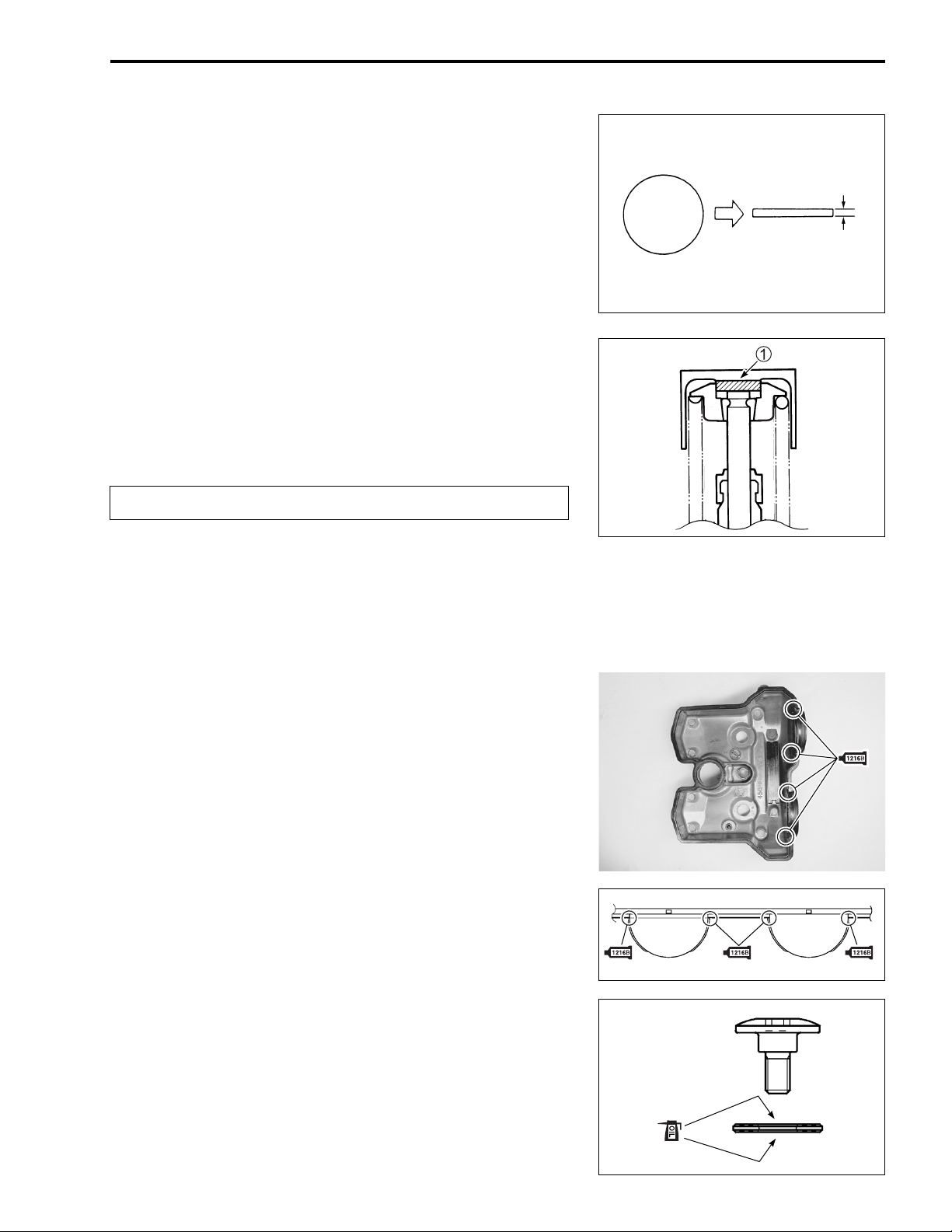
PERIODIC MAINTENANCE 2-7
• Check the numbers printed on the tappet shim. These numbers indicate the thickness of the tappet shim, as illustrated.
• Select a replacement tappet shim that will provide the proper
clearance. Tappet shims are available in 25 sizes, ranging
from 2.30 to 3.50 mm (0.09 to 0.14 in) in increments of 0.05
mm (0.002 in). Install the selected shim
1 at the valve stem
280
2.80 mm
end, with the numbers facing towards the tappet. Be sure to
measure the shim with a micrometer to ensure that it is of the
proper size.
Refer to the tappet shim selection table for details.
NOTE:
* Be sure to apply molybdenum oil solution to the top and bot-
tom faces of the tappet shim.
* When installing the tappet shim, make sure that the side with
the numbers face towards the tappet.
#
Install the camshafts as specified. (%3-76)
• After replacing the tappet shim and camshafts, rotate the
crankshaft so that the tappet is depressed fully (this will
squeeze out any oil trapped between the tappet shim and the
tappet that could cause an incorrect measurement). After
rotating the crankshaft, check the valve clearance again to
make sure that it is within specification.
• When installing the cylinder head cover, apply SUZUKI BOND
“1216B” to the cam end caps of the cylinder head cover gasket.
( 99000-31230: SUZUKI BOND “1216B”
• Tighten the generator cover cap and valve inspection plug.
(%3-78)
• Apply engine oil to both sides of the washers.
• Tighten the cylinder head cover bolts to the specified torque.
(%3-79)
" Cylinder head cover bolt:
Initial 10 N·m (1.0 kgf-m, 7.0 lb-ft)
Final 14 N·m (1.4 kgf-m, 10.0 lb-ft)
2-8 PERIODIC MAINTENANCE
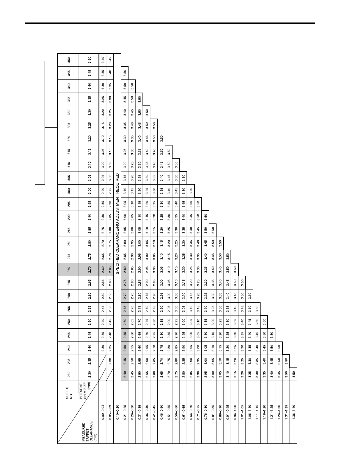
INTAKE SIDE
TAPPET SHIM SET NO.(12800-41810)
TAPPET SHIM SELECTION TABLE (INTAKE)
TAPPET SHIM NO. (12892-41C00-XXX)
How to use this chart:
I. Measure tappet clearance when the engine is cold.
II. Measure present shim size.
III. Match clearance in vertical column with present shim size in horizontal column.
Example:
Tappet clearance is 0.23 mm
Present shim size 2.70 mm
Shim size to be used 2.80 mm
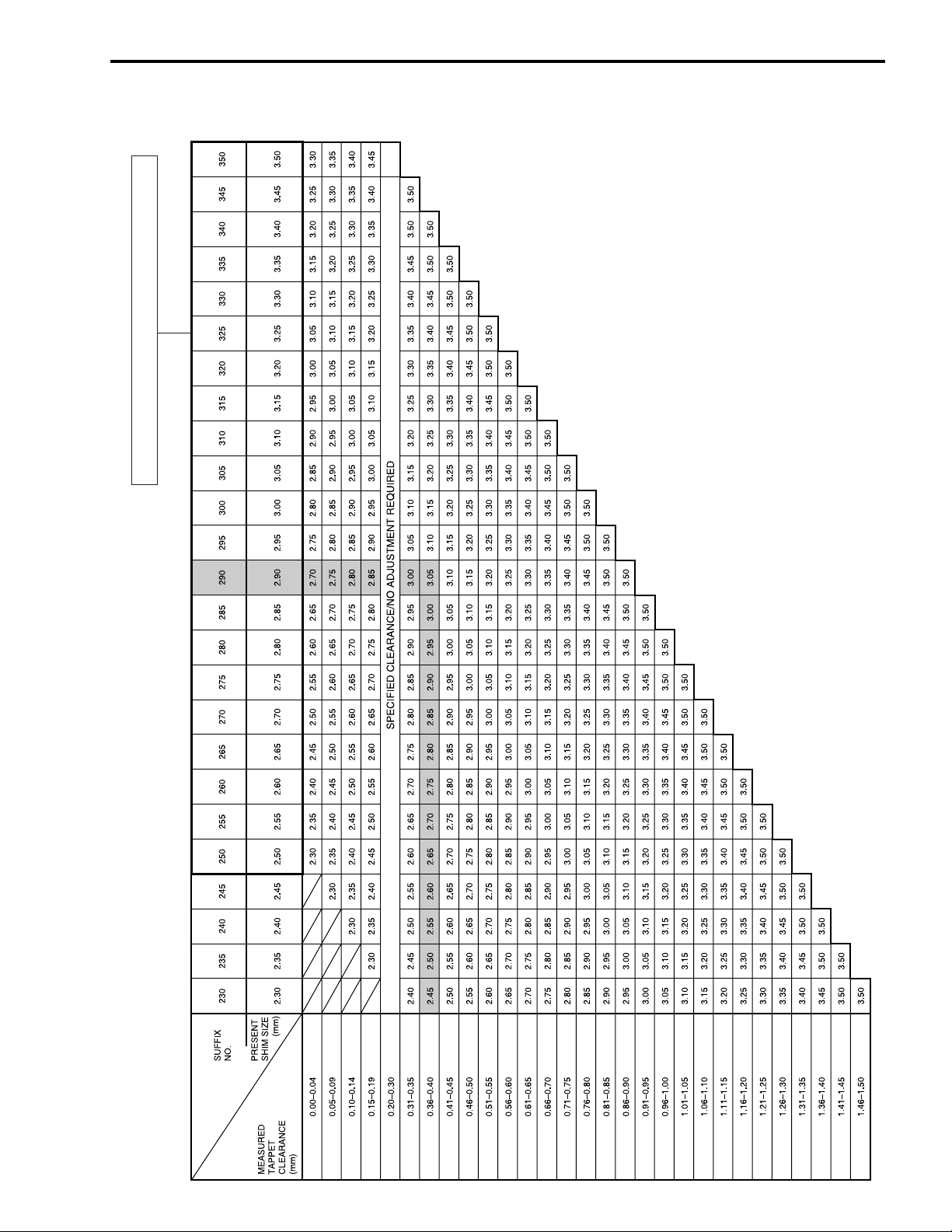
EXHAUST SIDE
TAPPET SHIM SET NO.(12800-41810)
PERIODIC MAINTENANCE 2-9
TAPPET SHIM SELECTION TABLE (EXHAUST)
TAPPET SHIM NO. (12892-41C00-XXX)
How to use this chart:
I. Measure tappet clearance when the engine is cold.
II. Measure present shim size.
III. Match clearance in vertical column with present shim size in horizontal column.
Example:
Tappet clearance is 0.38 mm
Present shim size 2.90 mm
Shim size to be used 3.05 mm
2-10 PERIODIC MAINTENANCE
SPARK PLUG
Inspect every 6 months.
Replace every 18 months.
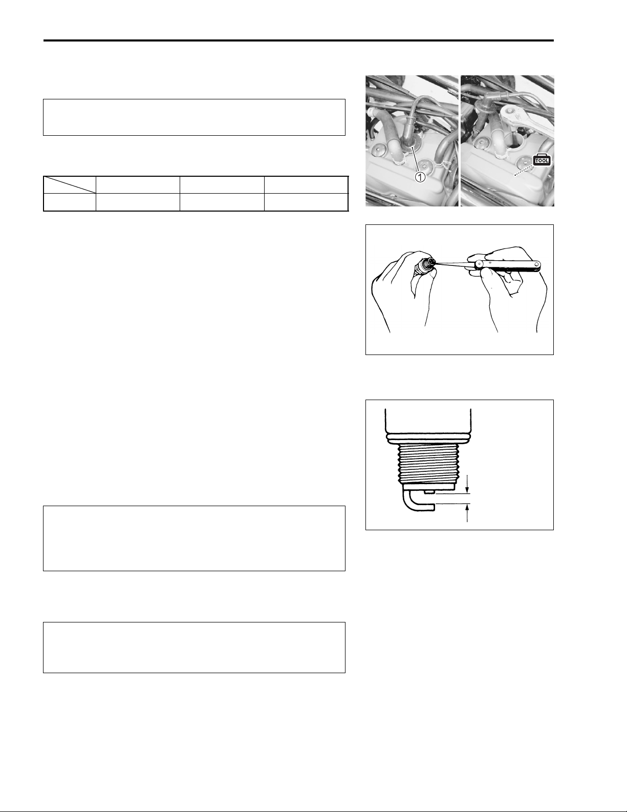
• Remove the fuel tank and fuel tank lower cover. (%5-4)
• Disconnect the spark plug cap
Hot type Standard Cold type
NGK CR7EB CR8EB CR9EB
CARBON DEPOSITS
Check to see if there are carbon deposits on the spark plug. If
carbon is deposited, remove it using a spark plug cleaner
machine or carefully use a tool with a pointed end.
1 and remove the spark plug.
SPARK PLUG GAP
Measure the spark plug gap using a thickness gauge. If the
spark plug gap is out of specification, adjust the gap.
' Standard
Spark plug gap: 0.7 – 0.8 mm (0.028 – 0.031 in)
& 09900-20803: Thickness gauge
ELECTRODE
Check the condition of the electrode.
If the electrode is extremely worn or burnt, replace the spark
plug with a new one.
Also, replace the spark plug if it has a broken insulator, damaged threads, etc.
#
Check the thread size and reach when replacing the
spark plug. If the reach is too short, carbon will be
deposited on the screw portion of the spark plug hole
and engine damage may result.
SPARK PLUG INSTALLATION
#
0.7 – 0.8 mm
(0.028 – 0.031 in)
To avoid damaging the cylinder head threads; first,
finger tighten the spark plug, and then tighten it to the
specified torque using the spark plug wrench.
• Insert the spark plug and finger tighten it to the cylinder head
and then, tighten it to the specified torque.
" Spark plug: 11 N·m (1.1 kgf-m, 8.0 lb-ft)
PERIODIC MAINTENANCE 2-11
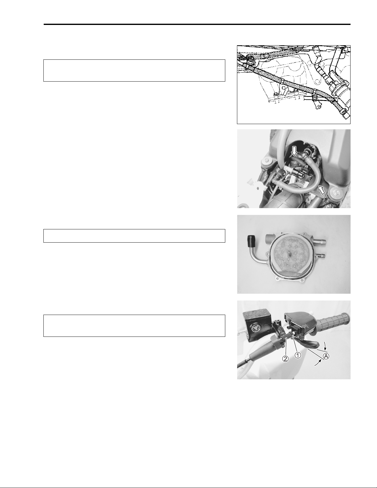
FUEL LINE
Inspect every 3 months.
Replace every 4 years.
Inspect the fuel hose for damage and fuel leakage. If any
defects are found, replace the fuel hoses with new ones.
FUEL FILTER
Replace every 4 years.
Inspect the fuel filter for damage and rust. If any defects are
found, blow the fuel filter with compressed air or replace the fuel
filter, O-ring and fuel filter cap with a new one. (%5-9)
THROTTLE CABLE PLAY
Inspect initially at 1 month and every 3 months thererafter.
Adjust the throttle cable play
• Loosen the lock-nut
• Turn the adjuster
' Throttle cable play: 3 – 5 mm (0.12 – 0.20 in)
• After adjusting the throttle cable play, tighten the lock-nut
2 in or out to obtain the correct play.
A as follows.
1 of the throttle cable.
1.
2-12 PERIODIC MAINTENANCE
ENGINE IDLE SPEED
Inspect initially at 1 month and every 3 months thereafter.
NOTE:
Make this adjustment when the engine is hot.
• Connect the tachometer to the high-tension cord.
• Start the engine and set the engine idle speed between 1 700
and 1 900 r/min by turning the idle air screw
' Engine idle speed: 1800 ± 100 r/min
1.
THROTTLE BODY
Inspect every 3 months.
Inspect the throttle body for dirt.
Clean the throttle body if necessary.
ENGINE OIL AND OIL FILTER
Replace initially at 1 month and every 6 months thereafter.
The oil should be changed while the engine is warm. Oil filter
replacement at the above intervals, should be done together
with the engine oil change.
5,
PERIODIC MAINTENANCE 2-13
ENGINE OIL REPLACEMENT
Crankcase side
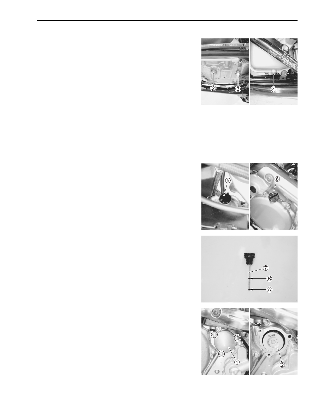
• Remove the engine protector cover
• Place an oil pan below the drain plug
case and drain plug
4 on the oil tank. Then drain out the
engine oil by removing the engine oil drain plug
engine oil filler cap
• Reinstall the drain plug
engine oil drain plug
6.
2, 3, 4 and gasket. Tighten the
2, 3 and 4 to the specified torque, and
1.
2 and 3 on the crank-
2, 3, 4 and
then pour the fresh oil through the oil filler hole. When performing an oil change (without oil filter replacement), the oil
tank will hold about 1.2 L (1.3 US qt, 1.1 lmp qt) of oil and the
engine will hold about 0.4 L (0.4 US qt, 0.4 lmp qt) of oil. Use
of SF/SG or SH/SJ in API with MA in JASO.
" Engine oil drain plug
Engine oil tank drain plug
2, 3: 18 N·m (1.8 kgf-m, 13.0 lb-ft)
4: 12 N·m (1.2 kgf-m, 8.5 lb-ft)
• Make sure that the engine is cooled.
• Place the motorcycle on level ground and hold it vertically.
• Install the oil filter cap
5, 6.
• Start the engine and allow it to run for three minutes at idling
speed.
• Turn off the engine and wait about three minutes, and then
check the oil level on the dipstick
between the “L” (low)
level is lower than the “L”
A and “F” (full) B level lines. If the oil
A level line, add oil to the “F” B
7. The oil level should be
level line.
NOTE:
Engine oil expands and oil level increase when the engine oil is
hot.
OIL FILTER REPLACEMENT
• Drain the engine oil as described in the engine oil replacement procedure.
• Remove the oil filter cap
1 and oil filter 2.
• Replace the oil filter with a new one.
 Loading...