

Suzuki PE250 1978 Owner's manual
same excellence
of
Isle
SUZUKI
any
race course in the world.
This
at
all
performance
We sincerely wish
;,1·-
riding.
f
that
has
produced
a long
Man as well as the motocross tracks
now
presents the
handbook
times. Your
from
is presented as a means whereby you can maintain
riding
your
you
new
skill
machine
and
your
PE250, a competition
and the maintenance steps
under
SUZUKI
any
of
type
history
of
Europe.
of
competition
motorcycle
world-championship racing
proved
racing machine, capable
your
PE250 in
outlined
in this manual
conditions.
a successful partnership
successes
top
will
for
many
at the famous
of
competing on
working
condition
assure you
years
of
of
top
happy
*
All
latest
any
information,
product
time
without
illustrations, photographs
information
available
notice.
at
the
SUZUKI
and
specifications contained in this manual are based on the
time
of
publication. The
right
is reserved to make changes
MOTOR CO.t LTD.
at
1
Nous vous presentons ici la nouvelle PE250, une machine de course qui a fait ses preuves en competition
et qui est capable de rivaliser sur tous les circuits du monde.
but
Ce Manuel a pour
PE250. Votre dexterite et les methodes d'entretien expliquees dans ce manuel vous permettront d'obtenir
de votre machine
Nous vous souhaitons sincerement,
et
de conduite eqresb!e.
tesmei/leures performances, que/les que soient les conditions de la competition.
de vous procurer Ie
a vous et a votre machine SUZUKI, de nombreuses ennees de succes
moyen
de maintenir toujours en excellente condition votre
* Toutes les informations, illustrations, photographies
besees sur les donnees les plus recentes concernant Ie produit, disponibles au
Nous nous reservons toutefois Ie droit
2
d'y
apporter des modifications a
et
specifications contenues dans ce manuel
tout
moment
Operating
Inspection
ENGINE
Engine removal 23
Engine
Inspection
Reassembling
CARBURETOR
ELECTRICAL
Ignition
Wire
CHASSIS
Front
Front
Steering
Rear
Rear
Rear
Wire
TROUBLESHOOTING
TIGHTENING
SPECIAL
SPECIFICATIONS
SERVICE
instruction
and
maintenance
Disassembly.
and
engine
system
routing
wheel.
fork.
shock
wheel
swinging
and
. . . . . . . . . . . . . . . . . . . . . . . .
. . . . . . . . . . . . . . . . . . . . . . . . .
absorber
arm
cables 65
TORQUE
TOOLS.
DATA
. . . . . . . . . . . . . . . . . . .
servicing
parts
. . . . . . . . . . . . . . . . . . . . . .
. . . . . . . . . . . . . .
engine
parts
. . . . . . . . . . . . . . .
, 68
..
..
..
..
..
..
, 78
11
25
30
35
41
47
52
53
55
57
59
61
63
66
71
76
7
Instructions
Inspectionetentretien
MOTEUR
Depose
Demontagedumoteur
Inspection
Remontage
CARBURATEUR
EQUIPEMENT
Circuit
Ciiblage
CADRE
Roue
Fourche
Direction
Amortisseurs
Roue
Bras
Fils
DEPISTAGE
COUPLES
OUTILS
FICHE
INFORMATIONS
du
moteur
et
des pieces du
d'allumage
avant
avant
arriere 61
oscillant
et
cables "
DES
DE
SERRAGE
SPECIAUX
TECHNIQUE
d'utilisation
. . . . . . . . . . . . . . . . . .
. . . . . . . . . . . . . . . . . .
entretien
ELECTRIQUE
arriere 59
arriere 63
PANNES
D'ENTRETIEN
des pieces du
moteur
. . . . . . . . . . . . . . . . . . . . .
moteur
. . . . . . . . . . .
..
..
.....
..
..
" 67
7
11
23
25
30
35
41
47
52
53
55
57
65
69
71
77
83
3
ENGINE
For
brands
*
*
* GOLDEN
OIL
the
oil to be
or its equivalent will
SHELL
CASTROL
SUPER M
R30
SPECTRO
mixed
with
gasoline, any of
do:
SYNTHETIC BLEND
the
* B.P. RACING
* BEL-RAY MC-1 TWO-CYCLE RACING LUBRICANT
CAUTION: Do
get mixed in
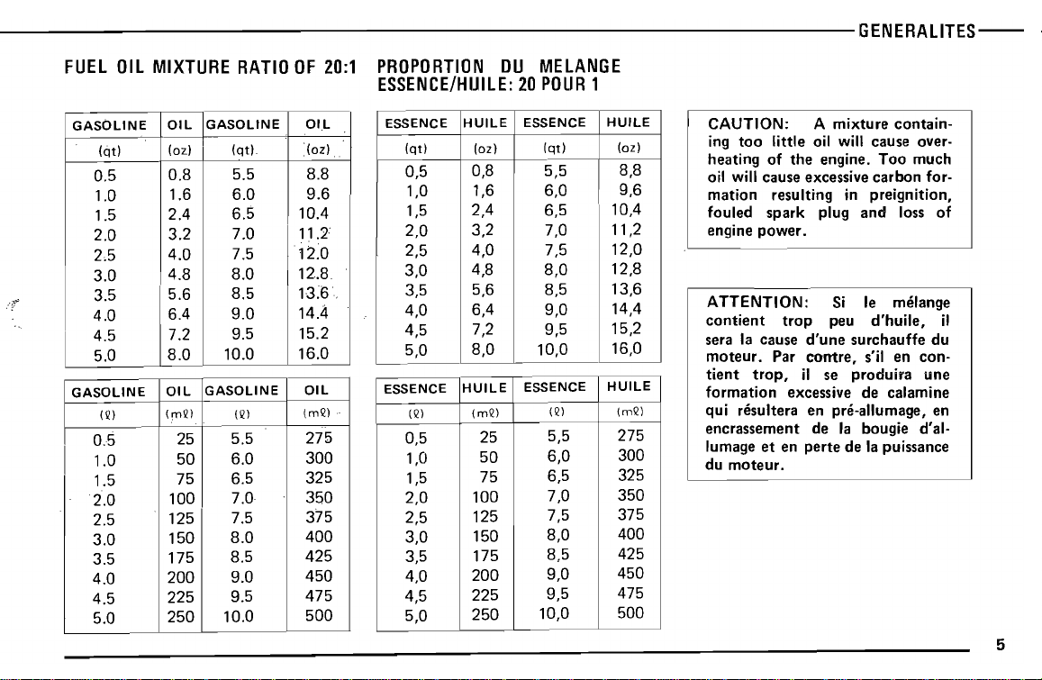
MIXING
20 parts gasoline to 1
mixture
ance, it is essential
be
4
RATIO
ratio
maintained.
for
the
fuel-oil
your
that
not
part
engine.
the
allow
two
mixture.
oil is
above fuel/oil
different brands
the
correct
For
proper
gasoline to oil
engine perform-
mixture
following
to
should
HUILE
On
suivantes ou leur
peut
DE
MOTEUR
utiliser
n'importe
equivalent
* SHE LL SUPER M
*
CASTROL
R30
* MELANGE SYNTHETIQUE GOLDEN SPECTRO
* B.P. RACING
* LUBRIFIANT
TEMPS BEL-RAY MC:1
ATTENTION:
differentes
RAPPORT
La
proportion
est
de 20 parties d'essence
obtenir
proportion
la
DU
des performances ideales, il est essentiel de respecter
POUR·
Ne jamais utiliser
pour
un meme melange d'essence-huile.
MELANGE
correcte
essence/huile precitee.
0.5
1.0
1.5
2.0
2.5
3.0
3.5
4.0
4.5
5.0
GASOLINE
(Q)
0.5
1.0
I
1.5
2.0
2.5
3.0
3.5
4.0
4.5
5.0
0.8
5.5 8.8
1.6 6.0
2.4
3.2
4.0
6.5
7.0
7.5
4.8 8.0
5.6
6.4
7.2
8.0
OIL
(mQ)
25
50
75
100
125
150
175
200
225
250
8.5
9.0
9.5
10.0
GASOLINE
(Q)
5.5
6.0
6.5
7.0
7.5
8.0
8.5
9.0
9.5
10.0
9.6
10.4
11.2
12.0
12.8.
13~6.
14.4
15.2
16.0
OIL
(mQ)
275
300
325
350
375
400
425
450
475
500
..
0,5
1,0
1,5
2,0
2,5
3,0
3,5
4,0
4,5
5,0
ESSENCE
(Q)
0,5
1,0
1,5
2,0
2,5
3,0
3,5
4,0
4,5
5,0
0,8 5,5
1,6 6,0
2,4 6,5
3,2
4,0
4,8
5,6 8,5
6,4 9,0
7,2 9,5
8,0
HUILE
(mQ)
10,0
ESSENCE
25
50
75
100
125
150
175
200
225
250
7,0
7,5
8,0
(Q)
5,5
6,0
6,5
7,0
7,5
8,0
8,5
9,0
9,5
10,0
8,8
9,6
10,4
11,2
12,0
12,8
13,6
14,4
15,2
16,0
HUILE
(mQ)
275
300
325
350
375
400
425
450
475
500
the
heating of
oil will cause excessive
mation
fouled
power.
engine
ATTENTION: Si Ie melange
contient
sera la cause
moteur.
tient
trop,
formation
qui resultera en pre-allumage, en
encrassement
lumage
du
et
moteur.
engine.
resulting in preignition,
spark
plug
trop
d'une
Par
contre,
il se
excessive de calamine
de la bougie d'al-
en
perte
Too
carbon
and
loss of
peu
d'huile,
surchauffe du
s'il en con-
produira
de la puissance
much
for-
une
il
5
6
Use a
good
FRONT
For
USE
To
replacement
any
SUZUKI
capability
costly
FORK
the
oil in
OF
replace
other
mechanical
quality
SAE20W/40
OIL
the
two
GENUINE
any
part
part. Imitation
source
than
origin in
of
the
machine
trouble.
legs, use a
SUZUKI
of
the
SUZUKI,
the
machine,
multi-qrads
motor
PARTS
machine,
and,
use a
parts
or parts
if used to replace
will
for
motor
oil of SAE 5W
genuine
supplied
lower
worse,
the
could
oil.
/20.
SUZUKI
from
parts
of
inherent
induce
Utiliser
-bonne
HUILE
Pour
moteur
une
qualite.
DE
les
deux
de
FOURCHE
SAE
UTILISATION
Pour
tout
pieces
remplacer
irnitees ou
risquent
machine,
coOteux.
travail de rem
SUZUKI
des pieces
obtenues
non
mais aussi de
huile
pattes
5W/20.
DE
seulement
CD
®
~~.
® ®
~J
.,l
"
;
',.".
~
(J)
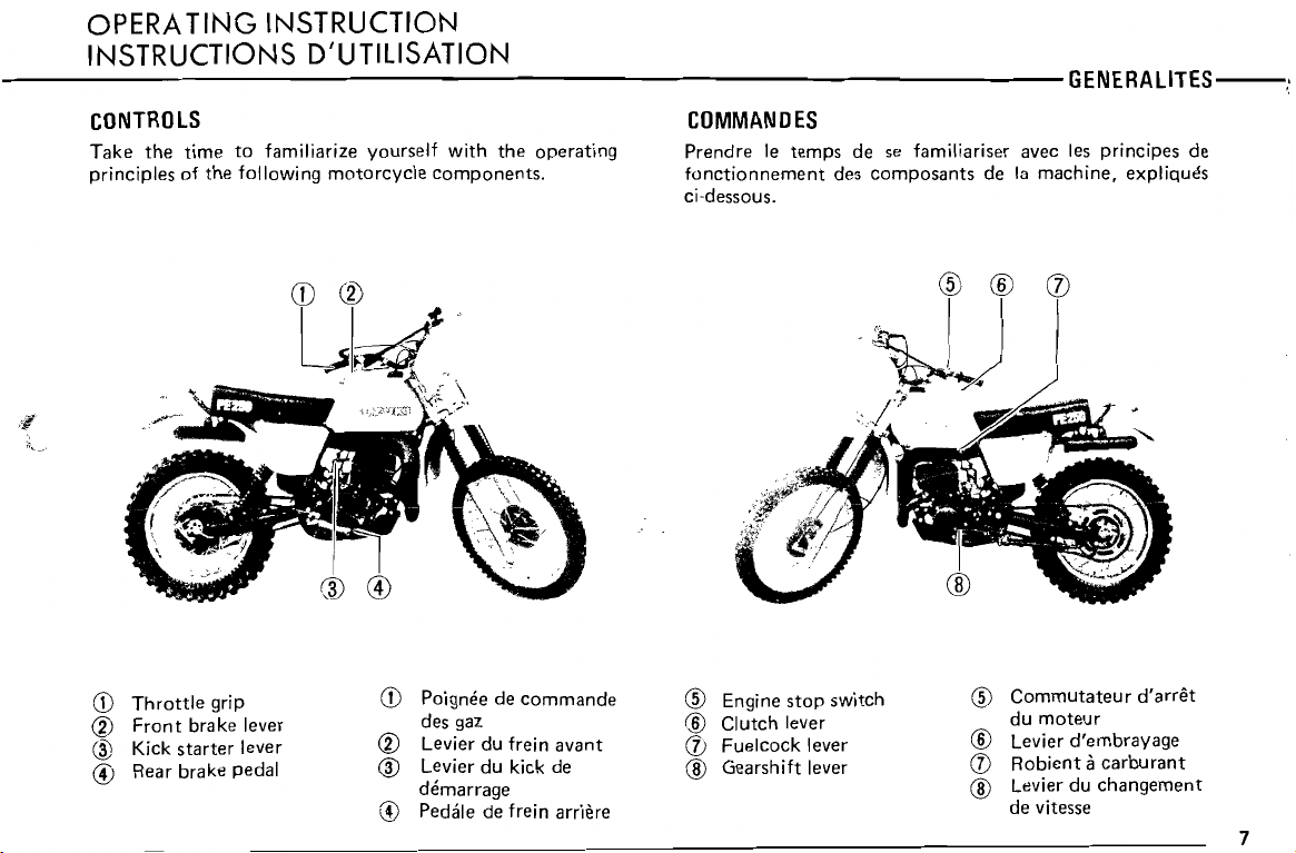
Throttle
CD
Front
CV
Kick starter lever
@
Hear brake pedal
@
grip
brake lever
Poiqnee de com mande
CD
des gaz
Levier du frein avant
CV
Levier du kick de
@
dernarraqe
@
Pedale de frein arriere
Engine
®
®
Clutch lever
(])
Fuelcock lever
@
Gearshift lever
stop
switch
Cornrnutateur
®
du moteur
Levier d'ernbravaqe
®
(])
Hobient
Levier du changement
@
de vitesse
a
carburant
d'arret
7
with
machine. Once
be assured of high
the
machine is fully
performance
in
competition.
broken
in,
you
can
kilometres (20 miles).
des pieces de se
avec la machine. Une fois
pouvez
petition.
etre
certain
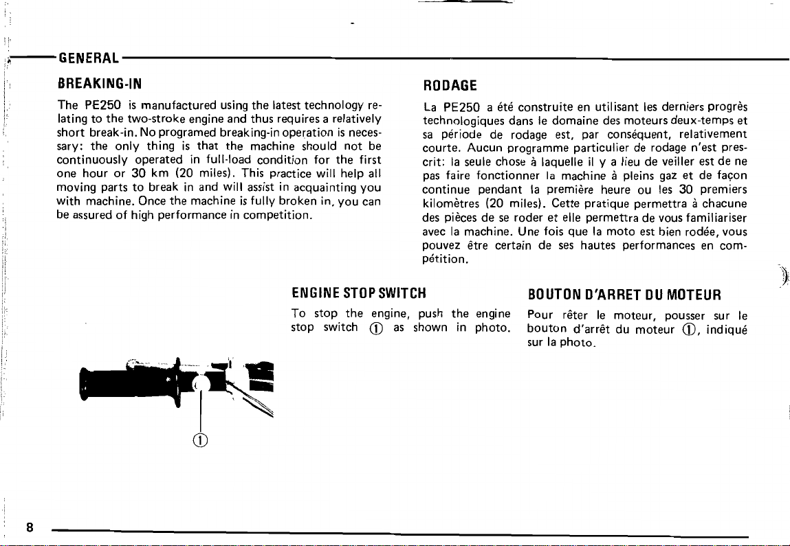
ENGINE
To
stop
stop
switch
STOP
the
engine, push
CD
SWITCH
as
shown
the
in
engine
photo.
~"'~'1!
~'I-~
CD
8
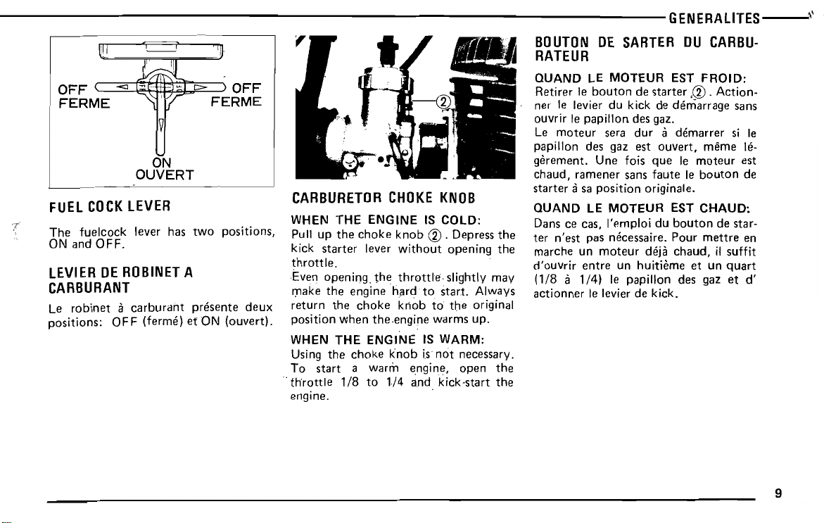
FUEL
COCK
The
fuelcock
ON and
LEVIER
OFF.
DE
ROBINET
CARBURANT
Le
robinet a carburant
positions:
OFF
ON
OUVERT
LEVER
lever has
two
positions,
A
presents
(terrne) et ON (ouvert).
deux
CARBURETOR
WHEN THE ENGINE IS COLD:
Pull up
kick
throttle.
Even
make
return
position
WHEN THE ENGINE IS WARM:
Using
To
.
throttle
engine.
the
starter
opening.
the
the
when
the
start a warm
1/8
choke
lever
the
engine
choke
the.enqine
choke
to
CHOKE
knob
without
throttle
hard
to
knob
knob
is
engine,
l/4
and
KNOB
® .Depress
opening
slightly may
start.
to
the
warms
not
necessary.
open
kick-start
the
the
Always
original
up.
the
the
Le
moteur
papillon des gaz est
gerement.
chaud,
starter
QUAND LE MOTEUR EST CHAUD:
Dans ce cas, I'emploi du
ter
n'est
marche un
d'ouvrir
(1/8 a 1/4)
actionner
sera
dur
Une fois
ramener
asa
entre
sans
position
pas necessaire.
moteur
Ie levier de kick.
originale.
deja
un huitierne et un
Ie papillon des gaz et
a dernarrer si Ie
ouvert,
que
faute
Ie
moteur
Ie
bouton
Pour
chaud,
rnerne le-
bouton
de star-
mettre
if
suffit
quart
est
de
en
d'
9
10
e
4
e
3
e
2
mort
Point
Premiere
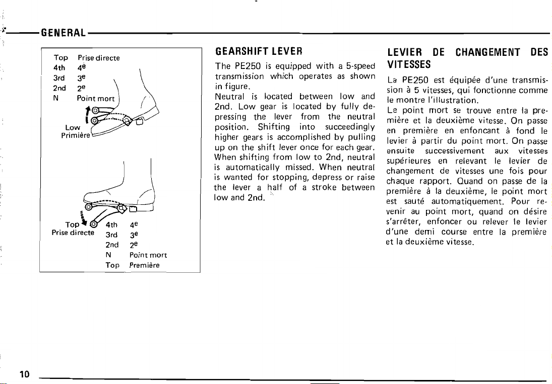
up on
the
When
shifting
is
automatically
is
wanted
the
lever a
low and
shift lever
for
half
2nd.
once
from
low
missed.
stopping,
of a
for
to
2nd,
When
depress
stroke
each
between
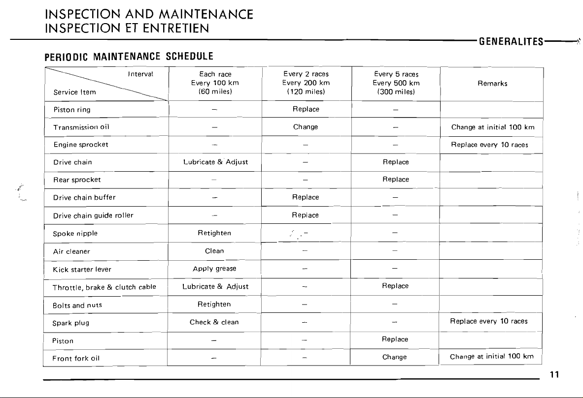
Every
(120
Replace
Change
Replace
Replace
200
miles)
km
Every
(300
500
miles)
km
Throttle.
Bolts
I
Spark
~
I Piston
Front
brake & clutch
and
nuts
plug
fork
oil
cable
~
Lubricate & Adjust
Check
Retighten
& clean
I
-
~
RePlace-----i
----1
I
Replace every 10 races
Replace
Change
i
Change at
initial
100
k~
11
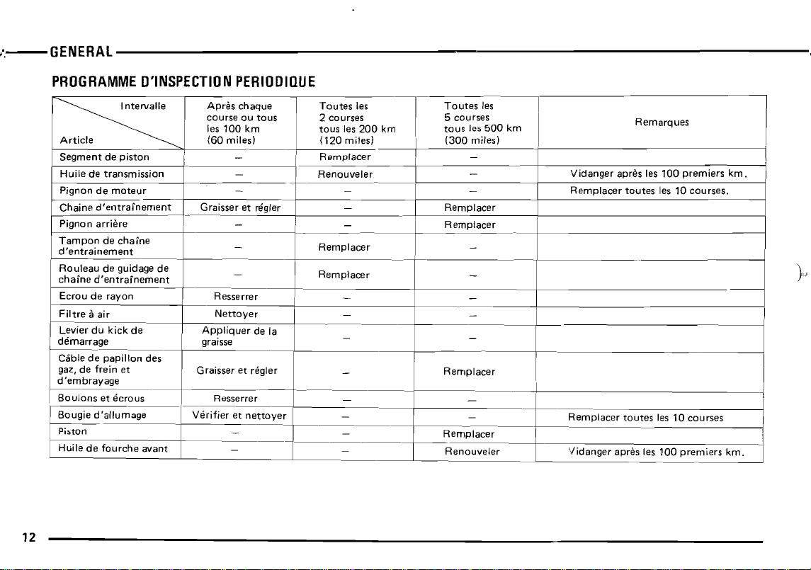
Pignon de
Chaine
Pignon
Tampon
d'entralnement
Ro~leau
chaine
Ecrou de rayon Resserrer
Filtre
~;ier
demarrage
Ciible de papillon des
gaz, de frein et
d'embrayage
1------
Boulons
Bougie
Piston
Huile de
moteur
d'entrafnement
arriere
de
de quidaqe de
d'entralnement
aair
du kick de
et
d'allumage
.
fourche
chaine
ecrous
avant
12
- - -
Graisser et regler -
- -
_
-
---t
Nettoyer
Appliquer
graisse - -
Graisser et regler
Verifier et
de la
Resserrer
nettoyer
_
-
Rempl cer
a
Remplacer
--------j--------+-------------------i
_ _
- -
_
_
--I----
--
- -
_
-
._+-
__
R_e_m--'pe.-Ie.-a_c_er
Remplacer
_
_
------+-------------------1
Remplacer
_
Remplacer
Renouveler
-.r'\......
M55
·f
.---
...
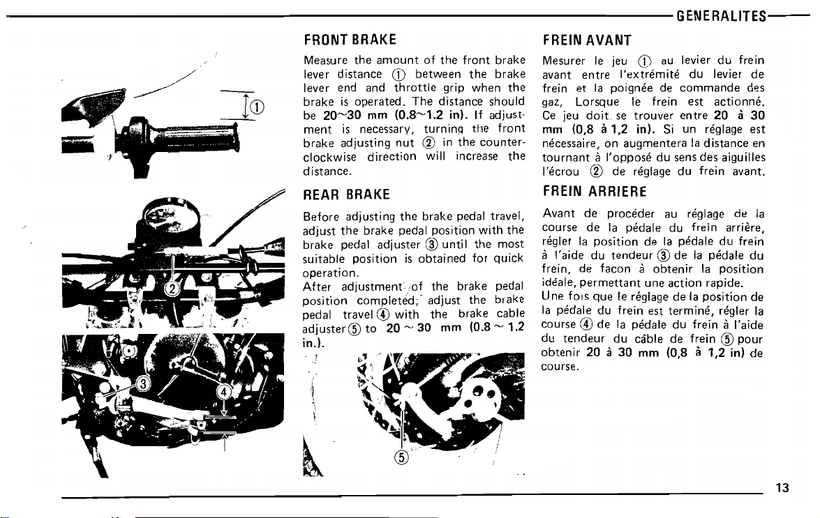
ICD
.~
ment
is
necessary,
brake
adjusting
clockwise
distance.
REAR
Before
adjust
brake
suitable
operation,
After
position
pedal travel @
adjuster@
in.1.
A
J
;
,
direction
BRAKE
adjusti
the
brake
pedal
adjuster ® until
position
adjustment
completed;'
to
l''J '; /
".-
"-
~;~
\.
'~~I
~
turning
nut
CV
will increase
ng
the
brake
pedal
is
obtained
of
adjust
with
20 ~ 30
~V:'
the
1~'.·8
......
(~f'
.
the
in
the
counter-
pedal
the
for
brake
the
brake
"i
travel,
with
quick
brake
..
pedal
cable
~
position
the
mm (0.8 ~ 1.2
front
most
the
the
mm
necessaire , on
tournant
l'ecrou
FREIN
Avant
course
reqler la
a I'aide du
frein,
ideale,
Une fors
la
course @ de
du
obtenir
course.
....
.'
.'
pedals
tendeur
(0,8 a1,2
augmentera
11
l'oppose
CV
de reglage
ARRIERE
de
proceder
de
la
position
tendeur
de
facon a obtenir
permettant
que
Ie reqlaqe
du frein est
la
du
20 a
30
in). Si un reqlaqe
la
distance
du sens
pedals
de la
® de fa
une
pedale
cable
mm
des
du
frein
au reqlaqe de la
du
frein
pedale
peda!e
la
action
rapide.
de
la
position
terrnine,
du
frein
de
frein @ pour
(0,8 a 1,2
est
en
aiguilles
avant.
arriere,
du
frein
du
position
de
reqler la
aI'aide
in) de
13
14
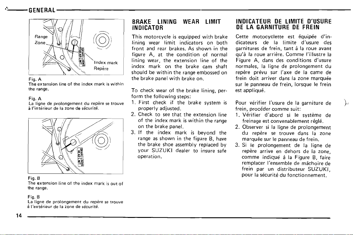
Fig. A
extension
The
the range.
Fig.
A
La ligne de
a
l'Interieur
B
Fig.
The
extension
the range.
Fig. B
La Iigne de
a
lexterieur
line
of
the
index
prolongement
de la zone de securite.
line
prolongement
de la zone de securite.
of
du repine se
the
index
du repere se
mark
mark
is
within
trouve
is
out
trouve
of
should
the
brake
To
check
form
1.
First
properly
2.
Check
of
on
3. If
range as
the
your
operation.
be
the
following
check
the
the
the
brake
SUZUKI
within
panel
wear
adjusted.
to see
index
brake
index
shown
shoe
the
with
of
the
steps:
if
the
that
mark
panel.
mark
in
assembly
dealer
range
embossed
brake
on.
brake
brake
the
extension
is
with
in
is
beyond
the
figure B, have
replaced
to insure safe
lining, per-
system
line
the
range
the
on
is
by
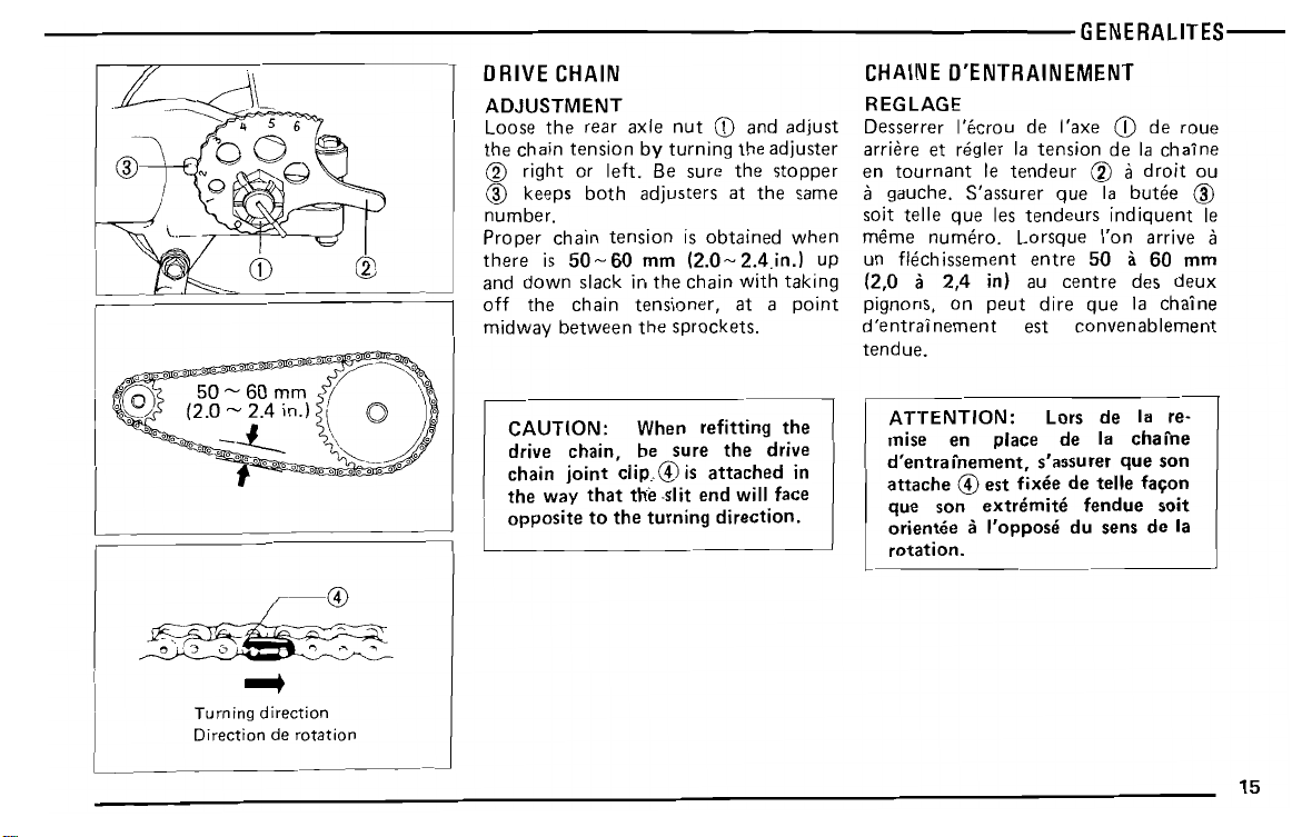
number.
Proper
there
and
down
off
the
midway
chain
is
50~60
slack in
chain
between
tension
mm
the
tensioner,
the
is
obtained
(2.0-2.4.in.)
chain
with
at a
sprockets.
when
up
taking
point
soit telle
rnerne
un flech
(2,0 a
pignons, on
d'entrainement
tendue.
que
nurnero.
issement
2,4
les
tendeurs
Lorsque
entre
in) au
peut
est
indiquent
I'on
50 a 60
centre
dire
que
convenablement
arrive a
des
deux
la
chaine
Ie
mm
,.,
"
~~
..,
...
Turning
direction
Direction
de
rotation
CAUTION: When refitting
drive chain, be sure
chain
joint
clip
..
the
way
opposite
that
to
@ is
the
the
turning direction.
the
attached
-slit end will face
the
drive
in
ATTENTION: Lors de la re-
mise en place de la chafne
d'entrafnement,
attache
que son
orisntee a I'oppose du sens de la
rotation.
@ est fixee de telle facon
s'assurer
extremite
que
fendue
son
soit
15
16
?
/).
- .
-II
Standard
Front
Rear
Taille
de
Avant
Arriere
tire
size:
3.00-21-4PR,
4.50-18-4PR,
pneu
standard:
3.00-21-4PR,
Entierernent
4.50-18-4PR,
Entierernent
Full
Full
apaves
apaves
knobby
knobby
proper
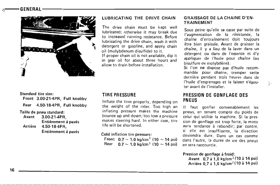
If
in gear oil for
allow
TIRE
I
nflate
the
inflating
bounce
makes
life will be
Cold
Front
Rear
chain
to
drain
PRESSURE
the
tires
weight
pressure
up and
steering
shortened.
inflation
0.7 ~ 1.0
0.7 ~ 1.0
oil is
not
about
before
installation.
properly,
of
the
rider.
makes
down;
too
hard.
In
tire
pressure:
kg/em 2 (10 ~ 14
kg/em 2 (10 ~ 14
available,
three
depend
Too
the
Iowa
either
hours
high an
machine
pressure
case,
dip
and
ing on
tire
psi)
psi)
it
appliquer
bisulfure
Si I'on ne dispose pas
rnandee
derniere
I'huile
ter
PRESSION
PNEUS
II
pneus,
celui qui utilise la
sion de gonflage est
aura
si elle
deviendra
dans
en sera
Pression de gonflage a
.
:
.....
•
~
-r:
.~:
-.,.
@:J
.a.
/~~.
.,,0'
Oil
"">,
,'::':,,-----
~
.f
,~
c=:J
:;.
-"
~&.
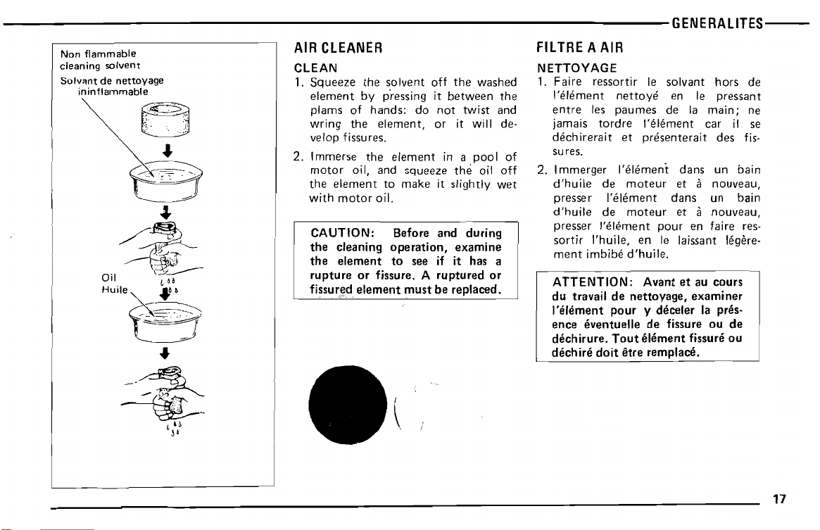
wring the element, or it will develop fissures .
2. Immerse
motor
the
with
CAUTION: Before and during
the cleaning operation, examine
the element to
rupture or fissure. A
fissured element must be replaced.
the
element in a poo I of
oil, and squeeze
element to make it slightly wet
motor
oil.
see if it has a
the
ruptured
oil off
or
jamais tordre I'element car if se
dechir
erait et
sures.
2. Immerger l'elernent dans un bain
d'huile
presser
d'huile
presser
sortir
ment
ATTENTION: Avant et au cours
du
I'element pour y
ence eventuelle de fissure ou de
dechirure.
dechire
l'elernent pour en faire res-
l'huile,
imbibe
travail
doit etre rernplace.
presenterait
de
moteur
l'elernent dans un bain
de
moteur
en Ie laissant legere-
d'huile
.
de nettoyage, examiner
Tout element fissure ou
deceler la
des fis-
et a nouveau,
et a nouveau,
pres-
..
-~
~
..
,;:
:
I
•
\
17
18
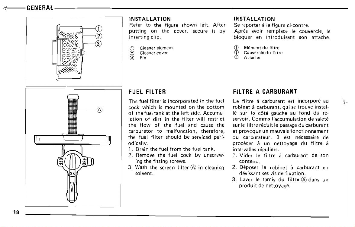
FUEL
FilTER
The fuel filter is incorporated in the fuel
cock which is mounted on
of the fuel tank at the left side. Accumu-
lation of dirt in the filter will restrict
the flow of the fuel and cause the
carburetor to malfunction, therefore,
the fuel filter should be serviced peri-
odically.
1. Drain the fuel from the fuel
2. Remove the fuel cock by unscrew-
ing the fitting screws.
3. Wash the screen filter
solvent.
the
bottom
tank.
® in cleaning
~
•
~
It_..
made
at
carburetor
the
cap.
cable
adjuster
on
the
faire
aI'aide du
couvercle du
tendeur
carburateur.
du cable sur Ie
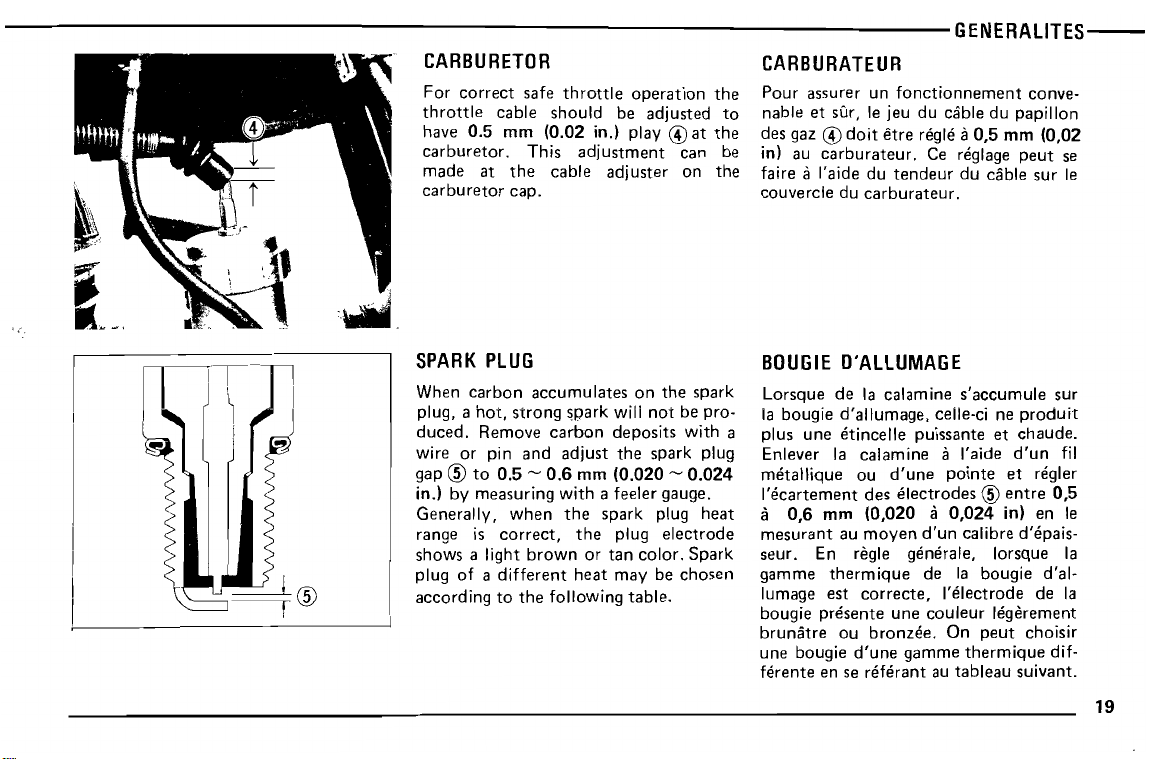
SPARK
When
plug, a
duced.
wire or pin
gap
in.] by measuring
Generally,
range is
shows a light
plug of a
according
carbon
®
PLUG
hot,
strong
Remove
to
0.5 ~ 0.6
when
correct,
different
to
accumulates
and
brown
the
spark
carbon
adjust
mm
with
a feeler gauge.
the
spark plug
the
or
tan
heat
following
on
the
wili
deposits
the
(0.020 ~ 0.024
plug
may
table.
spark
not
be pro-
with
spark plug
electrode
color.
Spark
be
chosen
heat
BOUGIE
Lorsque de la calamine s'accurnule sur
la bougie d'allurnaqe, celle-ci ne
a
plus
Enlever la calamine a l'aide
metallique
l'ecarternent
a
mesurant
seur. En regie generaIe, lorsque la
gamme
lumage est
bougie
brunatre
une bougie
ferente
O'ALLUMAGE
une
etincelle puissante et
ou
0,6
des
mm
(0,020 a 0,024
au
moyen
thermique
correcte,
presents
ou
bronzes.
d'une
en se
referant
d'une
pointe
electrodes ® entre
d'un
calibre d'epais-
de la bougie d'al-
l'electrode
une
couleur
gamme
au
legerement
On
peut
thermique
tableau
produit
chaude.
d'un
fil
et reqler
0,5
in) en Ie
de la
choisir
dif-
suivant.
19
20
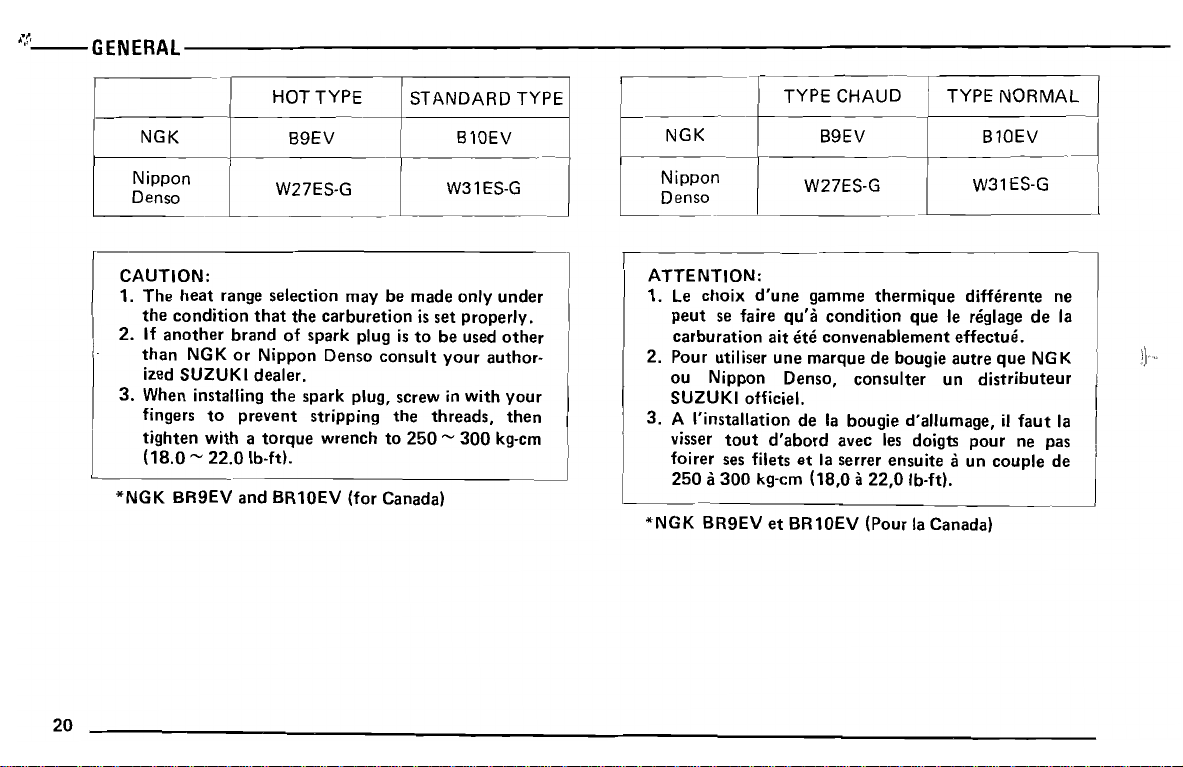
CAUTION:
1.
The
heat
range selection
the
condition
2. If
another
than
NGK
brand
or
ized SUZUKI dealer.
3.
When installing
fingers
tighten
to
with a torque
(18.0 -22.0
*NGK
BR9EV
and BR10EV
that
the
of spark plug is
Nippon
the
spark
prevent
Ib-ft).
may
be
made
carburetion is set
to
Denso
consult
plug, screw in
stripping
wrench
the
to
250 -300
(for Canada)
only
properly.
be used
your
with
threads,
under
other
author-
your
then
kg-cm
ATTENTION:
1. Le
choix
d'une
peut
se faire
carburation
2.
Pour
ou
Nippon
utiliser
ait
une
Denso,
SUZUKI officiel.
3. A I'installation de la bougie d'aJlumage,
visser
tout
d'abord
foirer ses filets
250 a300
*NGK
BR9EV
kg-cm (18,0 a
et
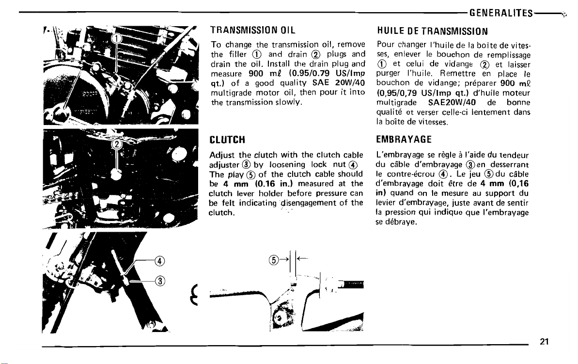
multigrade
the
transmission
motor
oil,
slowly.
then
pour
it
into
(0,95/0,79
multigrade
qualite
la boite de vitesses.
US/Imp
SAE20W/40
et
verser celle-ci
qt.]
d'huile
de
lentement
moteur
bonne
dans
CLUTCH
Adjust
adjuster ® by
The
be 4 mm
clutch
be
clutch.
f··
the
play ® of
lever
felt
indicating
EMBRAYAGE
the
can
the
du
d'embrayage
in)
levier
la pression
se debrave.
L'embrayage
Ie contre-ecrou
clutch
loosening
the
(0.16
holder
with
the
clutch
lock
clutch
measured
before
cable
pressure
in.]
disengagement
.
cable
nut
should
at
of
@
@-)II~.
-«:
, '\.0lIlIIII,"'"
cable
d'embrayage
quand
on Ie
d'ernbravaqe,
qui
se regie ii I'aide
® en
@.
etre
mesure
juste
indique
Le jeu ®
de
au
avant
que
doit
du
tendeur
desserrant
du
cable
4 mm
(0,16
support
de
sentir
I'embrayage
du
21
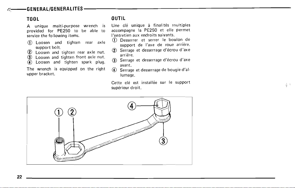
@
The
upper
Loosen
wrench
bracket.
and
is
equipped
tighten
spark
on
the
plug.
right
®
Serrage
avant.
@
Serrage
lumage.
Cette
cle
superieur
et
et
est
droit.
desserrage
desserrage
instailee
decrou
de
sur
bougie
Ie
support
d'axe
d'al-
22
CD®
®
tJl..1/J
®
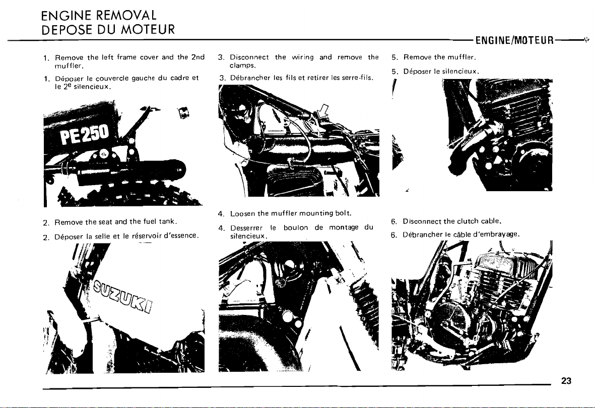
2.
2.
e
silencieux.
Ie 2
Remove
Deposer
Ih
the
la selle
P j
seat
and
the
et
Ie reservoir
fuel
tank.
d'essence.
Loosen
4.
4. Desserrer Ie
the
silencieux.
muffler
boulon
mounting
de
bolt.
montage
\,
du
...
,
•
"
6.
Disconnect
6.
Debrancher
the
clutch
Ie cable
cable.
d'embrayage.
23
24
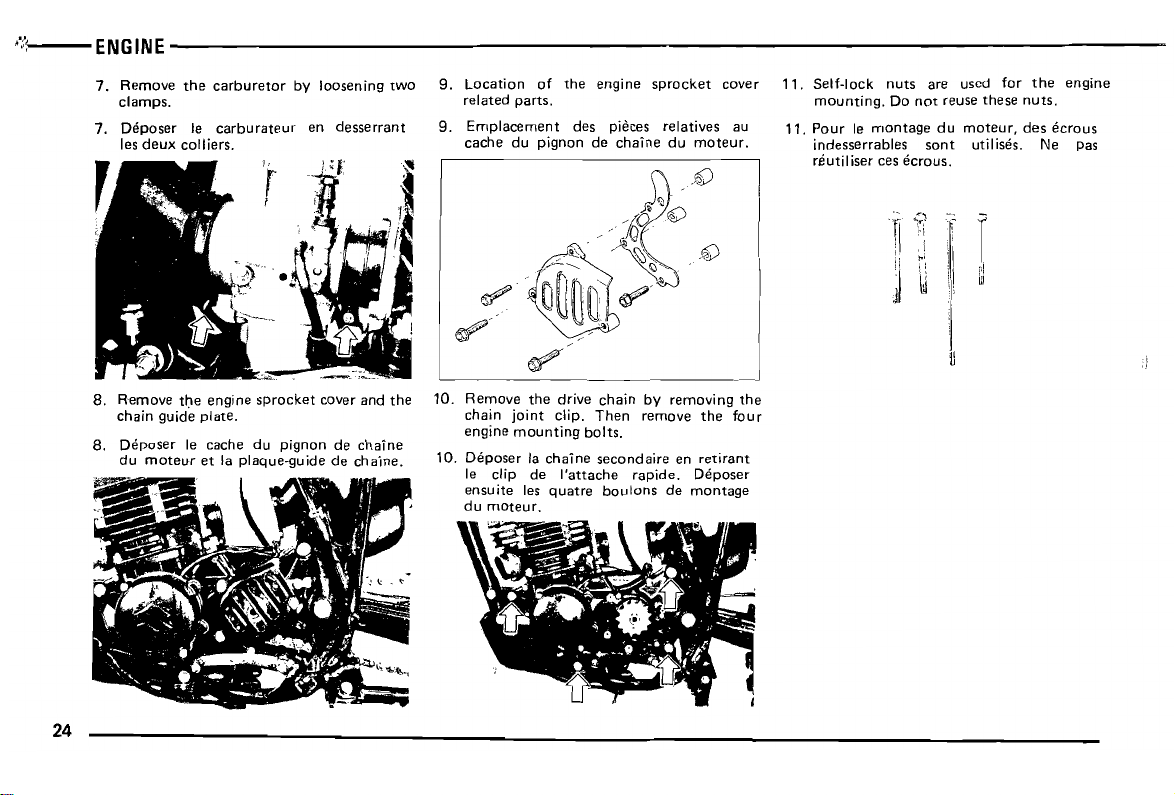
8.
8.
Remove
chain
guide
Deposer
du
moteur
the
engine
plate.
Ie cache du
et la
plaque-guide
sprocket
pignon
cover and
de ch
de
chaine.
the
aine
~.,
10.
Remove
chain
engine
10.
Deposer
Ie clip de
ensuite
du
~
moteur,
~
the
drive
joint
clip.
mounting
la
chaine
l'attache
les
quatre
,~'
Then
bolts.
secondaire
chain
by
remove
rapide, Deposer
boulons
de
.~
removing
the
en
retirant
montage
the
four
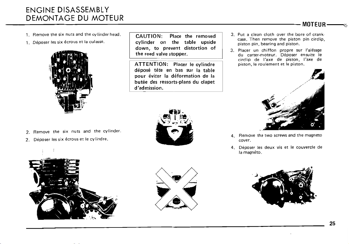
2.
2.
Remove
Deposer
the
les six
six
ecrous
nuts
and
et Ie
the
cylinder.
cylindre.
down,
the
reed valve stopper.
ATTENTION:
depose
pour
butee
d'admission.
prevent
to
tete
eviter
des ressorts-plans du clapet
Placer Ie cylindre
en bas sur la table
la
deformation
Wllt'-
:\~.~
i
l
..
. ~ c
!
l~.~~;"
'~".
U
..
~~
~
distortion
de la
".
of
3. Placer un
du
circlip de I'axe de
piston,
4.
Remove
cover.
4.
Deposer
la
magneto
chiffon
carter-moteur.
Ie
roulement
the
les
.
two
deux
propre
Deposer
piston,
et Ie
piston.
/,/''/
screws and
vis et Ie
sur
l'alesaqe
ensuite
I'axe de
s:
//
the
magneto
couvercle
Ie
~
...
de
25
26
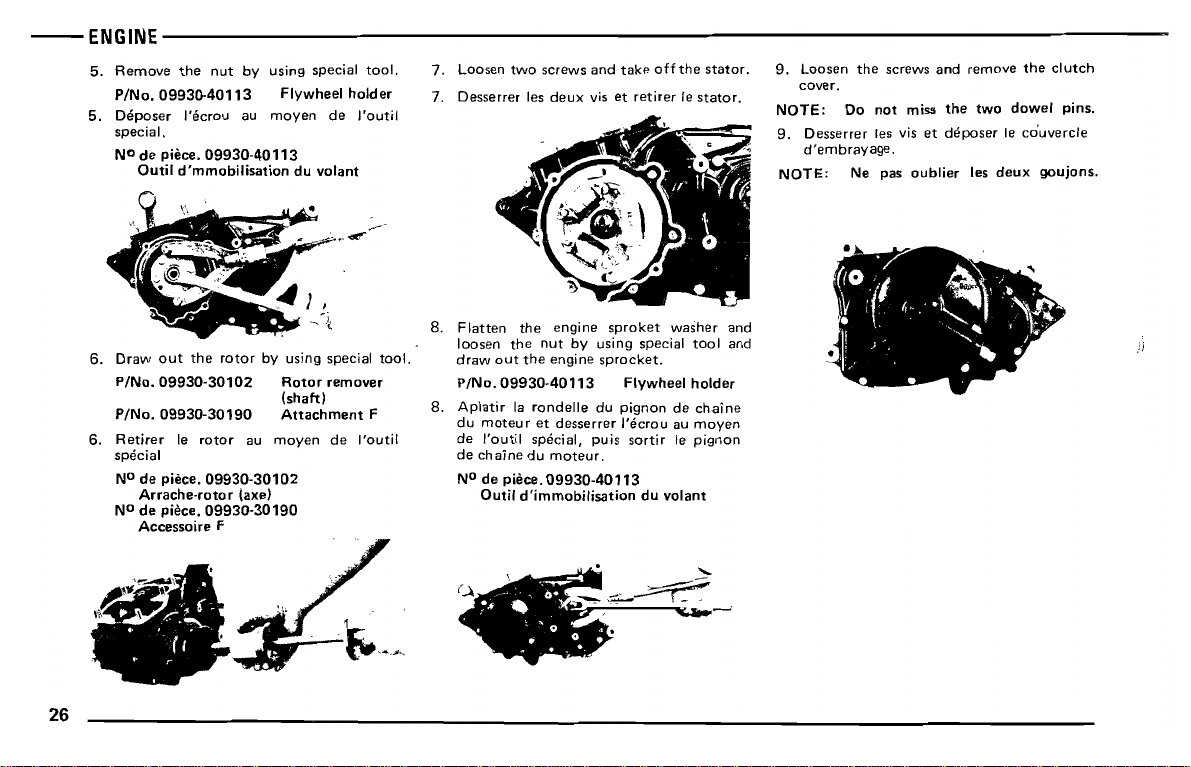
6.
Draw
out
P/No.09930·30102
P/No.09930·30190
6.
Retirer
special
NOde piece.
Arrache-roto
NOde piece.
Accessoire F
the
rotor
Ie
rotor
09930·30102
09930·30190
by using special tool.
Rotor
remover
(shaft)
Attachment
au
moyen
r (axe)
F
de I'outil
8.
Flatten
loosen
draw
P/No.09930·40113
8.
Aplatir
du
de I'outil special, puis
de
NOde piece.
the
the
out
the
la
rondelle
moteur
et
chaine
du
Outil
d'immobilisation
engine
nut
engine
moteur.
09930·40113
sproket
by using special
sprocket.
du piqnon de
desserrer I'ecrou au
washer
Flywheel
sortir
du
volant
Ie
tool
holder
chaine
moyen
pignon
and
and
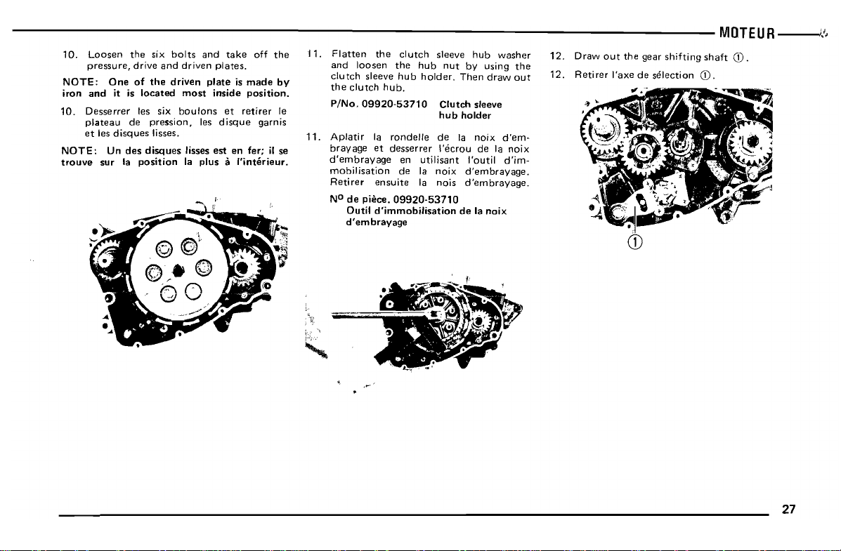
10.
NOTE:
trouve
Desserrer
plateau
et
les
disques
Un
sur la
les six
de
des
position
boulons
pression.
lisses.
disques
les
lisses est en fer; il se
la
plus a I'inter
et
disque
retirer
garnis
ieur.
Ie
11.
Aplatir
bray
d'embrayage
mobilisation
Retirer
NO
la
rondelle
age
et
desserrer
ensuite
de
piece.
Outil
d'embrayage
09920-53710
d'immobilisation
en
de la
hub
de la noix
i'ecrou
utilisant
noix
la nois
holder
d'em-
de la
noix
l'outil
d'im-
d'embrayage.
d'embrayage.
de la
noix
"
,t".'
27
 Loading...