

Suzuki K9K, M13 Service Manual
IMPORTANT
WARNING/CAUTION/NOTE
Please read this manual and follow its instructions carefully. To emphasize special information, the words
!
WARNING
lighted by these signal words.
!
WARNING
Indicates a potential hazard that could result in death or injury.
!
CAUTION
Indicates a potential hazard that could result in vehicle damage.
NOTE:
Indicates special information to make maintenance easier or instructions clearer.
!
WARNING
This service manual is intended for authorized Suzuki dealers and qualified service technicians only.
Inexperienced technicians or technicians without the proper tools and equipment may not be able to
properly perform the services described in this manual.
Improper repair may result in injury to the technician and may render the vehicle unsafe for the driver
and passengers.
!
, and NOTE have special meanings. Pay special attention to the messages high-
CAUTION
!
WARNING
For vehicles equipped with a Supplemental Restraint (Air Bag) System:
• Service on and around the air bag system components or wiring must be performed only by an
authorized SUZUKI dealer. Refer to “Air Bag System Components and Wiring Location View” under
“General Description” in air bag system section in order to confirm whether you are performing service on or near the air bag system components or wiring. Please observe all WARNINGS and “Service Precautions” under “On-Vehicle Service” in air bag system section before performing service
on or around the air bag system components or wiring. Failure to follow WARNINGS could result in
unintentional activation of the system or could render the system inoperative. Either of these two
conditions may result in severe injury.
• If the air bag system and another vehicle system both need repair, Suzuki recommends that the air
bag system be repaired first, to help avoid unintended air bag system activation.
• Do not modify the steering wheel, instrument panel or any other air bag system component on or
around air bag system components or wiring. Modifications can adversely affect air bag system
performance and lead to injury.
• If the vehicle will be exposed to temperatures over 93 °C (200 °F), for example, during a paint baking
process, remove the air bag system components, that is air bag (inflator) modules, SDM and/or seat
belt with pretensioner, beforehand to avoid component damage or unintended activation.
The circle with a slash in this manual means “Don’t do this” or “Don’t let this happen”.

RECOMMENDATON OF GENUINE SUZUKI PARTS AND ACCESSORIES USE
SUZUKI strongly recommends the use of genuine SUZUKI parts* and accessories. Genuine SUZUKI parts and
accessories are built to the highest standards of quality and performance, and are designed to fit the vehicle's
exact specifications.
A wide variety of non-genuine replacement parts and accessories for SUZUKI vehicles are currently available in
the market. Using these par ts and accessories can affect the vehicle performance and shorten its useful life.
Therefore, installation of non-genuine SUZUKI parts and accessories is not covered under warranty.
Non-Genuine SUZUKI Parts and Accessories
Some parts and accessories may be approved by certain authorities in your country.
Some parts and accessories are sold as SUZUKI a uthorized replacement par ts and accessor ies. Some genuine SUZUKI parts and accessor ies are sold as re-use parts and accessories. These par ts and accessories are
non-genuine Suzuki parts and accessories and use of these parts are not covered under warranty.
Re-use of Genuine SUZUKI Parts and Accessories
The resale or re-use of the following items which could give rise to safety hazards for users is expressly forbidden:
1) Air bag components and all other pyrotechnic items, including their components (e.g. cushion, control
devices and sensors)
2) Seatbelt system, including their components (e.g. webbing, buckles, and retractors)
The air bag and seat belt pretensioner components contain explosive chemicals. These components should be
removed and disposed of properly by SUZUKI authorized service shop or scrap yard to avoid unintended explosion before scrapping.
*The parts remanufactured under SUZUKI's approval can be used as genuine SUZUKI parts in Europe.
TABLE OF CONTENTS
GENERAL INFORMATION
General Information 0A 0B 6E2
Maintenance and Lubrication 0B
HEATING AND AIR CONDITIONING 1A 6G
Heater and Ventilation 1A
Air Conditioning (Optional) 1B Cranking System (M13 Engine) 6G 6H
STEERING, SUSPENSION, WHEELS AND
TIRES
Steering, Suspension, Wheels and Tires 3 Charging System (K9K Engine) 6H2 3B 6K2
Front Wheel Alignment 3A Exhaust System (M13 Engine) 6K 3B1
Steering Gear Box (Manual Type) and
Linkage
Power Steering (P/S) System (if equipped) 3B1 3E 7B
Steering Wheel and Column 3C Manual Transmission (M13 Engine Model) 7A 3F 7C
Front Suspension 3D Manual Transmission (K9K Engine Model) 7A2 7C2
Rear Suspension 3E Automatic Transmission 7B 4B 7D
Wheels and Tires 3F Clutch (M13 Engine Model) 7C 7E
DRIVE SHAFT AND PROPELLER SHAFT Clutch (K9K Engine Model) 7C2 5 7F
Propeller Shafts 4B Transfer 7D 5E
BRAKE SYSTEM
Brakes 5 Rear Differential 7F 6-1 8G
Antilock Brake System (ABS) 5E ELECTRICAL SYSTEM 6-2 8G2
ENGINE Body Electrical System 8 6-3
Engine General Information and Diagnosis
(M13 Engine without VVT)
Engine General Information and Diagnosis
(K9K Engine)
Engine General Information and Diagnosis
(M13 Engine with VVT)
Engine Mechanical (M13 Engine without
VVT)
Engine Mechanical (K9K Engine) 6A2
Engine Mechanical (M13 Engine with VVT) 6A3
Engine Cooling (M13 Engine) 6B
Engine Cooling (K9K Engine) 6B2
Engine Fuel (M13 Engine) 6C
Engine Fuel (K9K Engine) 6C2
3B
6-1
6-2
6-3
6A1
Engine and Emission Control System
(M13 Engine)
Engine and Emission Control System
(K9K Engine)
Ignition System (Electronic Ignition System)
Cranking System (K9K Engine) 6G2
Charging System (M13 Engine) 6H 3A 6K
Exhaust System (K9K Engine) 6K2
TRANSMISSION, CLUTCH AND DIFFERENTIAL
Front Differential 7E 8
Immobilizer Control System (M13 Engine
Model) (if equipped)
Immobilizer Control System (K9K Engine
Model)
BODY SERVICE
Body Service 9 6C
RESTRAINT SYSTEM
Restraint System 10
Air Bag System 10B
6E
6E2
6F 1B 6G2
8G
8G2
0A 6E
6F
3 6H2
3C 7A
3D 7A2
6A1 9
6A2
6A3 10
6B 10B
6B2
6C2
NOTE:
For the screen toned Section in the above table, refer to the same section of the Service Manuals men-
tioned in FOREWORD of this manual.
(C)
(B)
ENGINE MECHANICAL (K9K ENGINE) 6A2-5
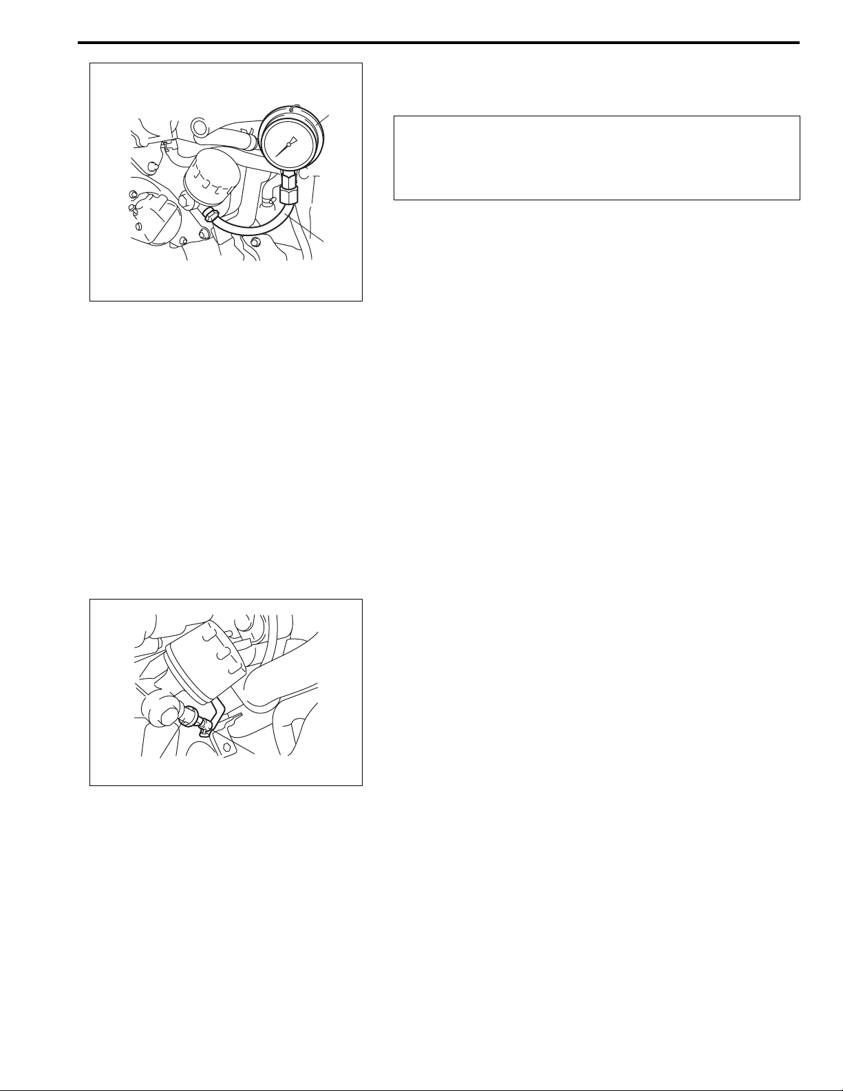
4) Install special tools (Oil pressure gauge) to vacated threaded
hole.
(A)
CAUTION:
Be careful not to make special tool touch exhaust mani-
fold when installing because exhaust manifold becomes
very hot.
Special tool
(A): 09915-77311
(B): 09915-77420
(C): 09915-77430
5) Start engine and warm it up to normal operating temperature.
NOTE:
Be sure to place transmission gear shift lever in “Neu-
tral” and set parking brake and block drive wheels.
1, (a)
6) After warming up, measure oil pressure.
Oil pressure specification:
2
100 – 140 kPa (1.0 – 1.4 kg/cm
, 14.2 – 20.0 psi) at idle
speed
330 – 370 kPa (3.3 – 3.7 kg/cm
2
, 46.9 – 52.5 psi) at 3,000 r/
min
7) Stop engine and remove oil pressure gauge and attachment.
8) Reinstall oil pressure switch (1), and tighten switch to specified torque.
Tightening torque
Oil pressure switch (a): 35 N·m (3.5 kg-m, 25.5 lb-ft)
9) Connect oil pressure switch coupler (2).
10) Install degassing tank to its bracket.
2
11) Start engine and check oil pressure switch for oil leakage.
If oil leakage is found, repair it.
6A2-6 ENGINE MECHANICAL (K9K ENGINE)
1
"1"
"2"
"3"
"4"
"5"
"6"
"7" "8"
Valve Lash (Clearance)
Measurement of valve lash (clearance)
1) Disconnect negative (–) cable at battery.
2) Remove cylinder head cover referring to “Cylinder Head
Cover Removal and Installation” in this section.
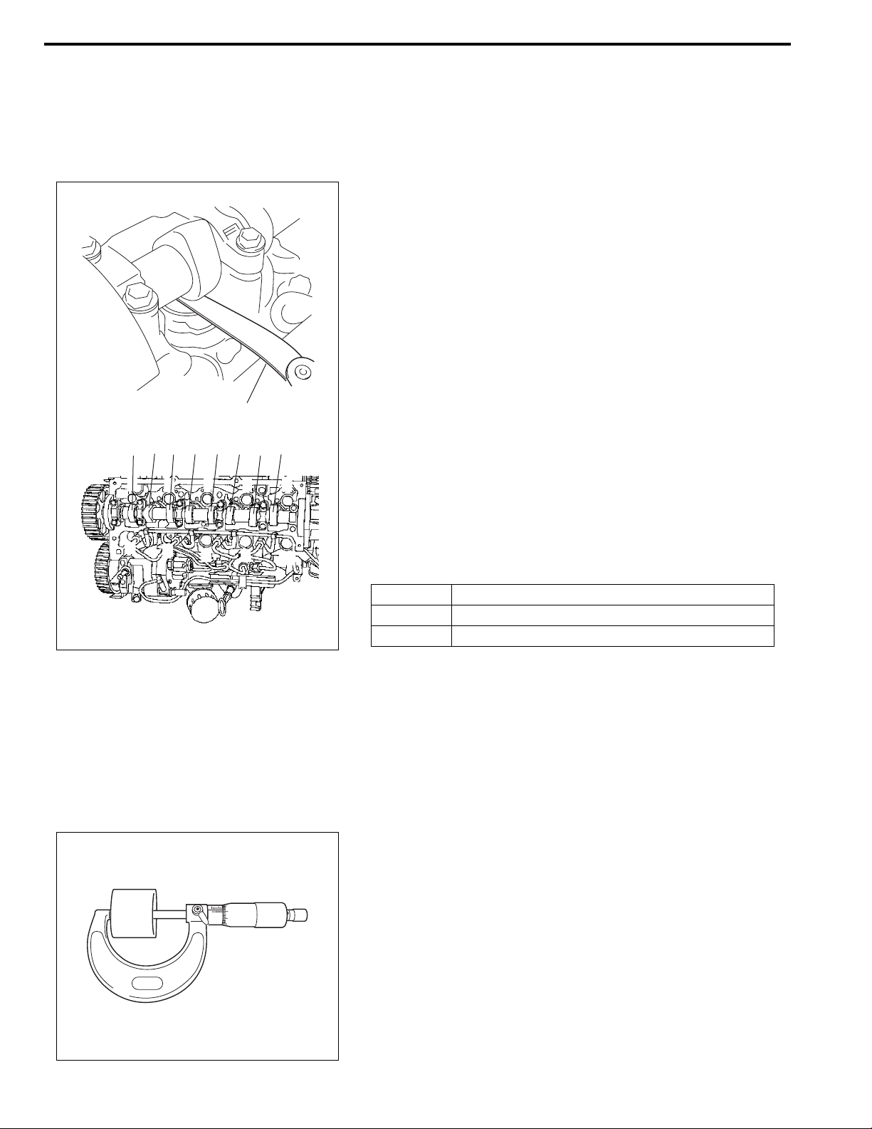
3) Turn crankshaft pulley clockwise until cam lobes become
perpendicular to tappet faces at valves “1” and “6” as shown
in figure.
4) Measure valve lashes with thickness gauge (1) according to
the following procedure.
a) Check valve lashes at valves “1” and “6”.
b) Turn camshaft by 90° (by turning crankshaft with wrench).
c) Make sure that cam lobes are perpendicular to tappet faces
at valves to be checked (in this case, “5” and “8”), if not,
adjust it by turning crankshaft. Check valve lashes.
d) In the same manner as b) – c), check valv e lashes at valves
“4” and “7”.
e) In the same manner as b) – c), check valv e lashes at valves
“2” and “3”.
If valve lash (clearance) is out of specification, record valve lash
(clearance) and adjust it to specification by replacing tappet.
Refer to “Replacement of tappet” under “Valve Lash (Clearance)”
in this section.
Valve lash (clearance) specification
When cold
Intake 0.125 – 0.250 mm (0.00493 – 0.00984 in.)
Exhaust 0.325 – 0.450 mm (0.01280 – 0.01771 in.)
Replacement of tappet
1) Measure valve lashes referring to “Measurement of Valve
Lash (Clearance)” under “Valve Lash (Clearance)” in this
section.
2) Remove tappet referring to “Camshaft and Tappet” in this
section.
3) Using micrometer, measure the thickness of the removed
tappet, and determine replacement tappet by calculating the
thickness of new tappet with the following formula and table.
Intake side
A = B + C – 0.1875 mm (0.007382 in.)
Exhaust side
A = B + C – 0.3875 mm (0.015256 in.)
A: Thickness of new tappet
B: Thickness of removed tappet
C: Measured valve lash (clearance)
ENGINE MECHANICAL (K9K ENGINE) 6A2-7
Example of intake side:
When thickness of removed tappet is 7.8875 mm (0.310531 in.),
and measured valve lash (clearance) is 0.200 mm (0.00787 in.).
A = 7.8875 mm (0.310531 in.) + 0.200 mm (0.00787 in.) – 0.1875
mm (0.007382 in.) = 7.900 mm (0.31102 in.)
Calculated thickness of new tappet = 7.900 mm (0.31102 in.)
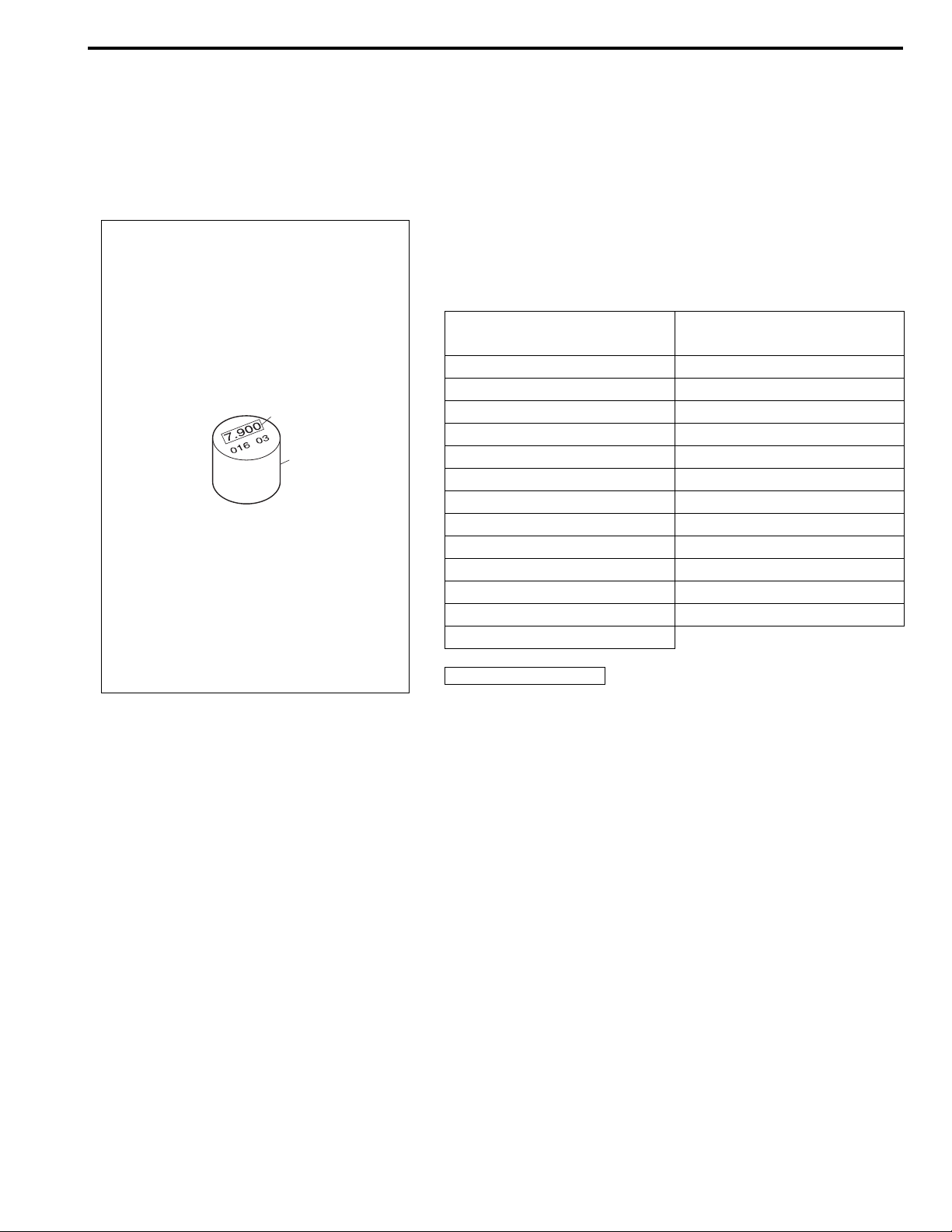
4) Select new tappet (1) with a thickness as close as possible
to calculated value.
Available new tappets
Thickness
mm (in.)
Thickness
mm (in.)
7.550 mm (0.29724 in.) 7.875 mm (0.31004 in.)
7.575 mm (0.29823 in.) 7.900 mm (0.31102 in.)
2
7.600 mm (0.29921 in.) 7.925 mm (0.31201 in.)
7.625 mm (0.30020 in.) 7.950 mm (0.31299 in.)
1
7.650 mm (0.30118 in.) 7.975 mm (0.31398 in.)
7.675 mm (0.30217 in.) 8.000 mm (0.31496 in.)
7.700 mm (0.30315 in.) 8.025 mm (0.31595 in.)
7.725 mm (0.30413 in.) 8.050 mm (0.31693 in.)
7.750 mm (0.30512 in.) 8.075 mm (0.31791 in.)
7.775 mm (0.30610 in.) 8.100 mm (0.31890 in.)
7.800 mm (0.30709 in.) 8.125 mm (0.31988 in.)
7.825 mm (0.30807 in.) 8.150 mm (0.32087 in.)
7.850 mm (0.30906 in.)
2. Tappet thickness
5) Install new tappet and camshaft referring to “Camshaft and
Tappet Removal and Installation” in this section.
6) Measure valve lashes again referring to “Measurement of
Valve Lash (Clearance)” under “Valve Lash (Clearance)” in
this section.
7) Install cylinder head cover referring to “Cylinder Head Cover
Removal and Installation” in this section.
6A2-8 ENGINE MECHANICAL (K9K ENGINE)
Repair Instructions
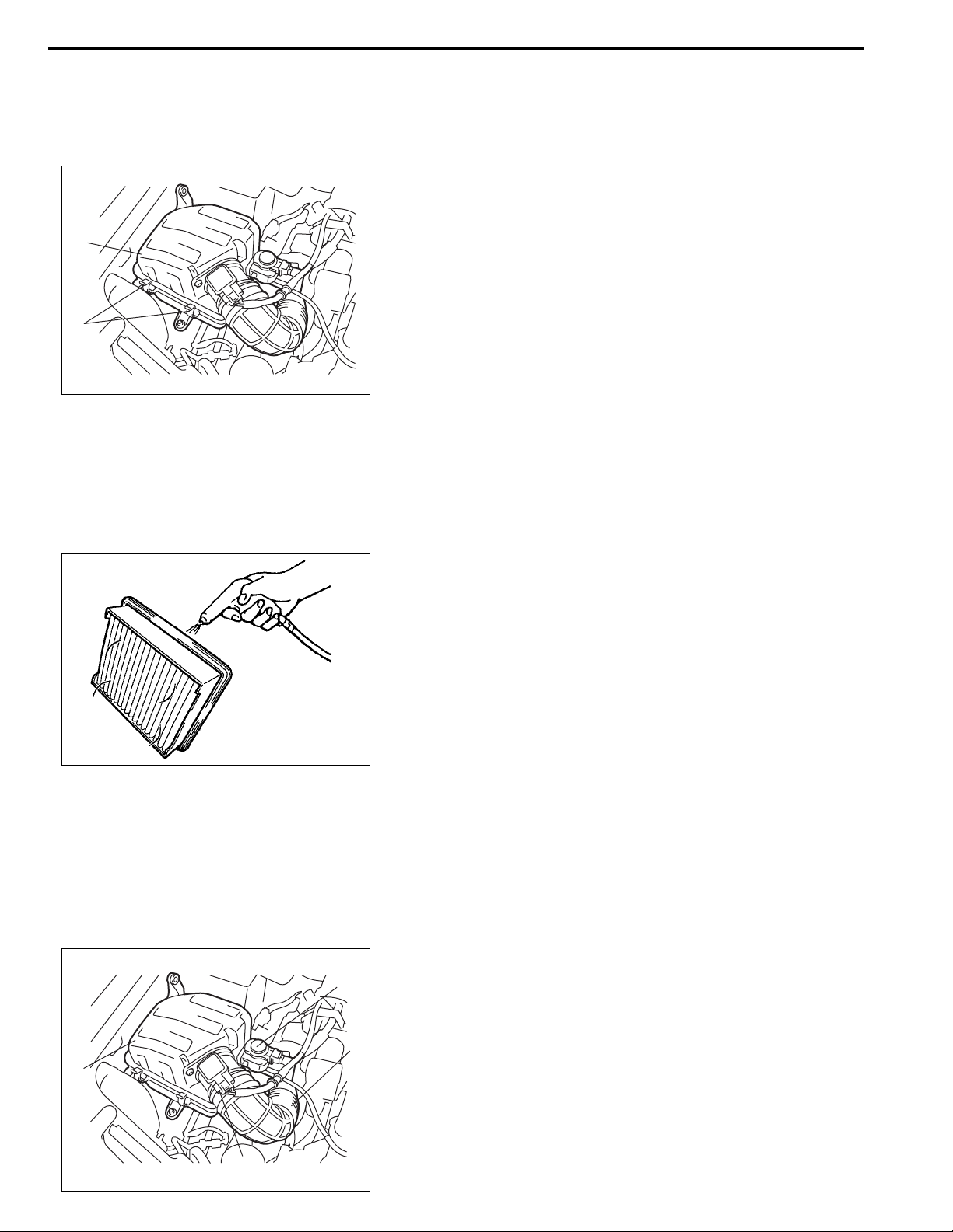
Air Cleaner Filter Removal and Installation
Removal
1) Open air cleaner case (2) unhooking its clamps (1).
2) Remove air cleaner filter from case.
2
Installation
Reverse removal procedure for installation.
1
Air Cleaner Filter Inspection and Cleaning
Inspection
Check filter for dirt. Replace if excessively dirty filter.
Cleaning
When cleaning filter, blow off dust by compressed air from air outlet side of filter. (i.e., the side facing up when installed in air
cleaner case.)
Air Cleaner Assembly Removal and Installation
Removal
1) Disconnect negative (–) cable at battery.
2) Remove boost pressure control solenoid valve (4) from air
cleaner assembly.
3) Disconnect MAF and IAT sensor connector (1).
4
2
3
1
4) Disconnect air cleaner outlet hose (2) from air cleaner
assembly (3).
5) Remove air cleaner assembly from vehicle.
1, (a)
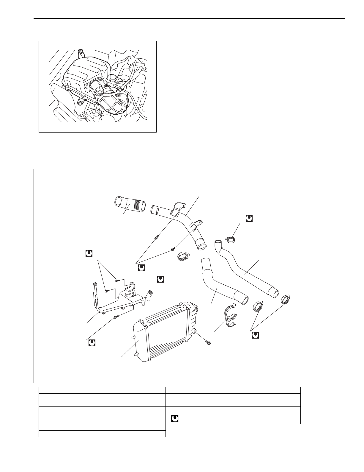
Intercooler Components
ENGINE MECHANICAL (K9K ENGINE) 6A2-9
Installation
Reverse removal procedure for installation noting the following.
• Tighten air cleaner outlet hose clamp (1) to specified torque.
Tightening torque
Air cleaner outlet hose clamp (a):
2.5 N·m (0.25 kg-m, 2.0 lb-ft)
8
25 N·m (2.5 kg-m)
2
25 N·m (2.5 kg-m)
8
6
7
11
28 N·m (2.8 kg-m)
9
4 N·m (0.4 kg-m)
4
3
1
10
9
5 N·m (0.5 kg-m)
5
4 N·m (0.4 kg-m)
1. Intercooler 8. Intercooler bracket bolt
2. Intercooler bracket 9. Intercooler hose clamp No.1
3. Intercooler hose clamp 10. Intercooler hose clamp No.2
4. Intercooler outlet hose No.1 11. Intercooler outlet pipe bolt
5. Intercooler inlet hose Tightening torque
6. Intercooler outlet pipe
7. Intercooler outlet hose No.2
6A2-10 ENGINE MECHANICAL (K9K ENGINE)
3
4
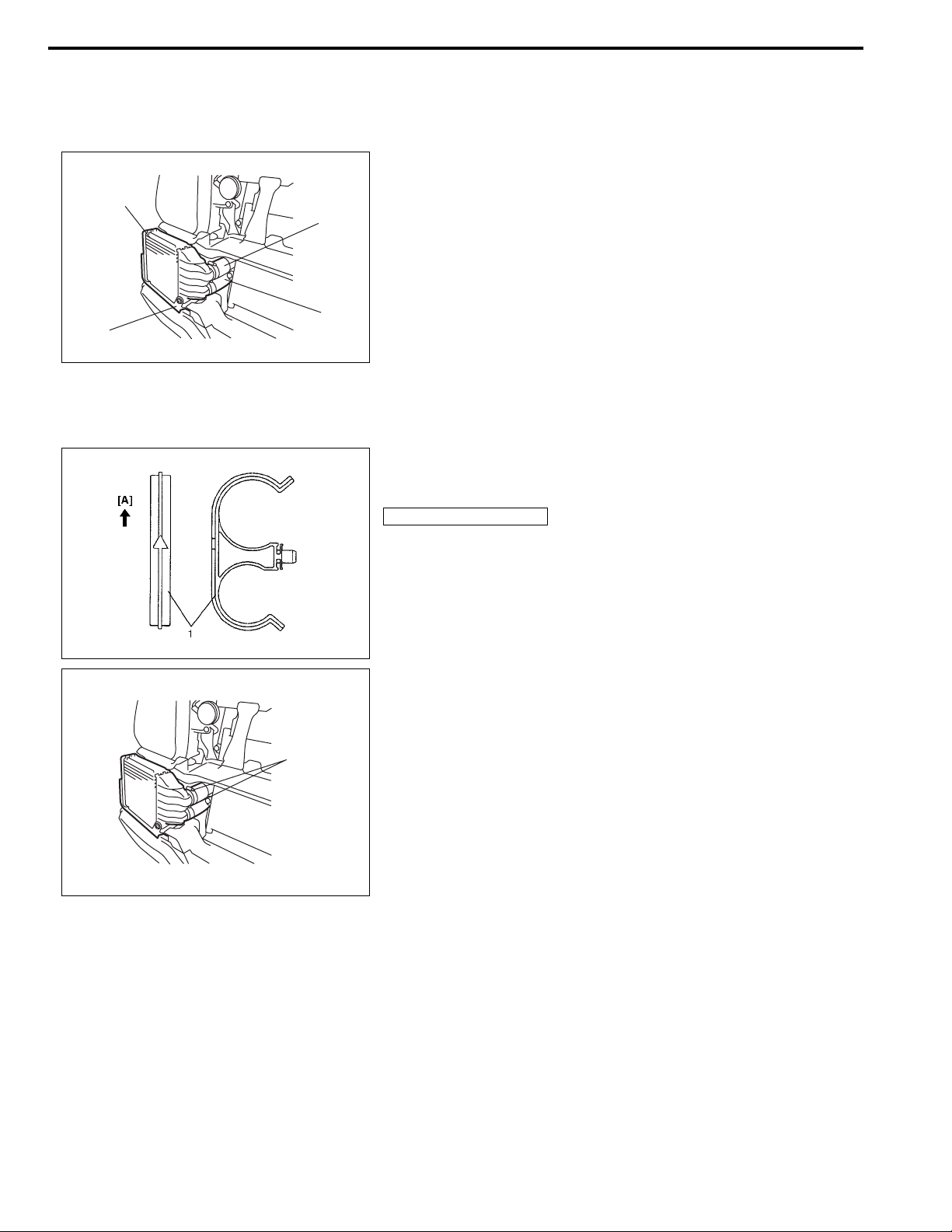
Intercooler Removal and Installation
Removal
1) Remove front bumper.
2) Remove intercooler inlet hose (1) and outlet hose (2) from
intercooler.
2
1
3) Remove intercooler (3) and its bracket (4).
Installation
Reverse removal procedure for installation noting the following.
• Install intercooler hose clamp (1) in specified direction as
shown in figure.
1, (a)
[A]: Upper side
• Tighten intercooler bracket bolts and intercooler hose
clamps (1) to specified torque.
Tightening torque
Intercooler bracket bolt: 25 N·m (2.5 kg-m, 18.0 lb-ft)
Intercooler hose clamp No.1 (a): 4 N·m (0.4 kg-m, 3.0 lb-ft)
• Install front bumper.
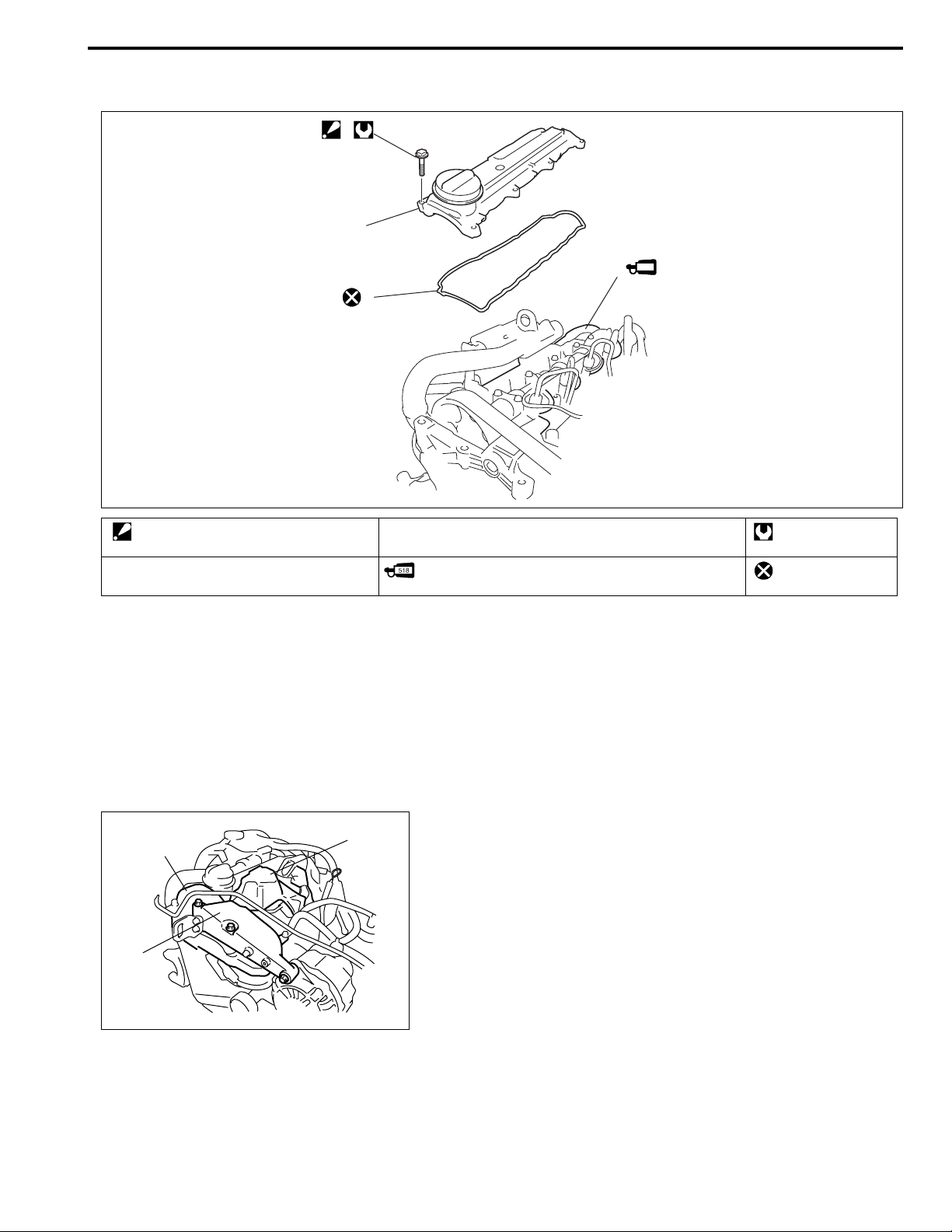
Cylinder Head Cover Components
1
2
3
ENGINE MECHANICAL (K9K ENGINE) 6A2-11
518
4
1. Cylinder head cover bolt
: Tighten 12 N·m (1.2 kg-m, 9.0 lb-ft) by
the specified procedure.
2. Cylinder head cover 4. Cylinder head
3. Cylinder head cover gasket
: Apply Loctite 518® referring to “Installation” under “Cylinder Head Cover Removal and Installation”.
Cylinder Head Cover Removal and Installation
Removal
1) Disconnect negative (–) cable at battery .
2) Remove drive belt referring to “Generator Drive Belt
1
3
2
3) Remove injector cover (1), generator upper bracket (2), tim-
4) Disconnect breather hose from cylinder head cover.
Tightening torque
Do not reuse.
Removal and Installation” in Section 6H2.
ing belt upper cover (3) and injector return hose cover .
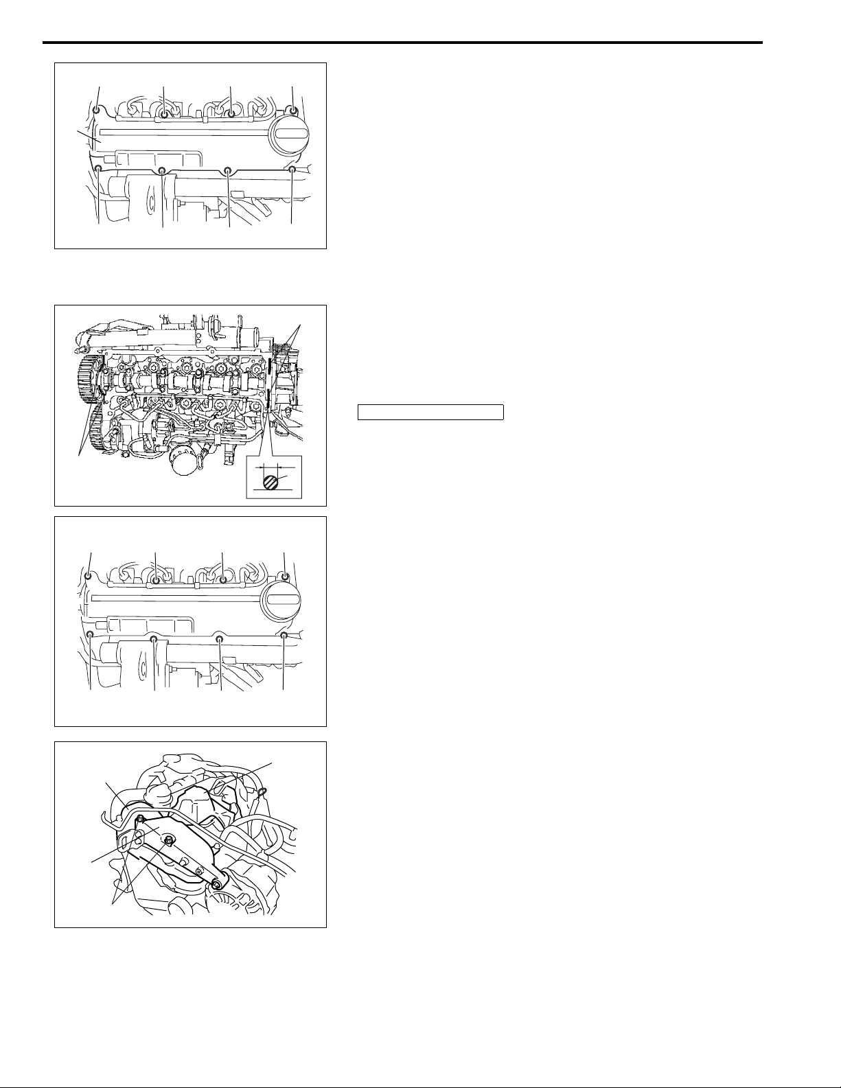
6A2-12 ENGINE MECHANICAL (K9K ENGINE)
“A”
“1”
“5”
“7”
“3”
5) Loosen cylinder head cover bolts in such order (“1” to “8”) as
shown in the figure and remove them.
6) Remove cylinder head cover (1).
1
“2”
“6”
“8”
“4”
Installation
“A”
1) Remove oil, old sealant and dust from sealing surfaces. After
cleaning, apply sealant “A” to cylinder head sealing surface
area as shown in the figure.
“A”: Loctite 518®
“a”: 2 mm (0.08 in.)
“a”
“A”
“8”, (a)
“7”, (a)
1
2
(a)
“4”, (a)
“3”, (a)
“2”, (a)
“1”, (a)
“6”, (a)
“5”, (a)
3
2) Install cylinder head cover to cylinder head as follows.
a) Fit cylinder head cover to cylinder head with new gasket.
b) Tighten cylinder head cover bolts temporarily by hand.
c) Tighten cylinder head cover bolts specified torque by
numerical order as shown in figure.
Tightening torque
Cylinder head cover bolt (a):
Tighten 12 N·m (1.2 kg-m, 9.0 lb-ft) by the specified procedure
3) Connect breather hose to cylinder head cover.
4) Install injector return hose cover, timing belt upper cover (1),
generator upper bracket (2) and injector cover (3).
Tightening torque
Generator upper bracket bolt (a):
40 N·m (4.0 kg-m, 29.0 lb-ft)
5) Install drive belt referring to “Generator Drive Belt Removal
and Installation” in Section 6H2.
6) Connect negative (–) cable at battery.
ENGINE MECHANICAL (K9K ENGINE) 6A2-13
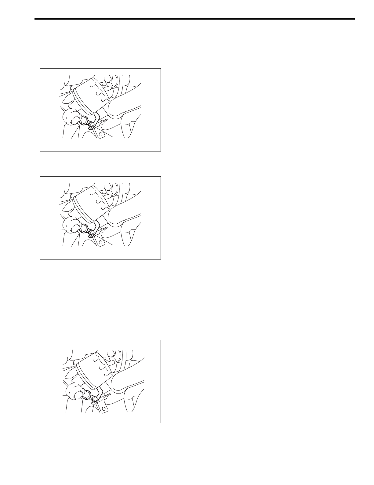
Oil Pressure Switch Removal and Installation
Removal
1) Disconnect negative (–) cable at battery .
2) Detach degassing tank from its bracket.
3) Disconnect oil pressure switch connector (1).
4) Remove oil pressure switch (2).
1, (a)
2
1
Installation
1) Install oil pressure switch (1) with new gasket.
2) Tighten oil pressure switch (1) to specified torque.
Tightening torque
Oil pressure switch (a): 35 N·m (3.5 kg-m, 25.5 lb-ft)
3) Connect oil pressure switch connector (2).
4) Install degassing tank to its bracket.
2
5) Start engine and check for oil leakage.
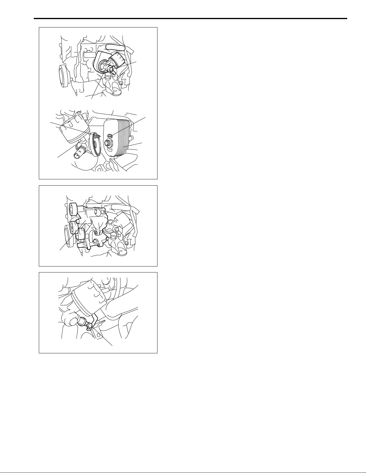
Heat Exchanger Removal and Installation
Removal
1) Disconnect negative (–) cable at battery .
2) Drain engine coolant referring to “Coolant Replacement” in
Section 6B2.
3) Detach degassing tank from its bracket.
4) Disconnect oil pressure switch connector (1).
5) Remove generator referring to “Generator Dismounting and
Remounting” in Section 6H2.
6) Remove compressor referring to “Compressor” in Section
1B.
7) Remov e radiator outlet hose.
1
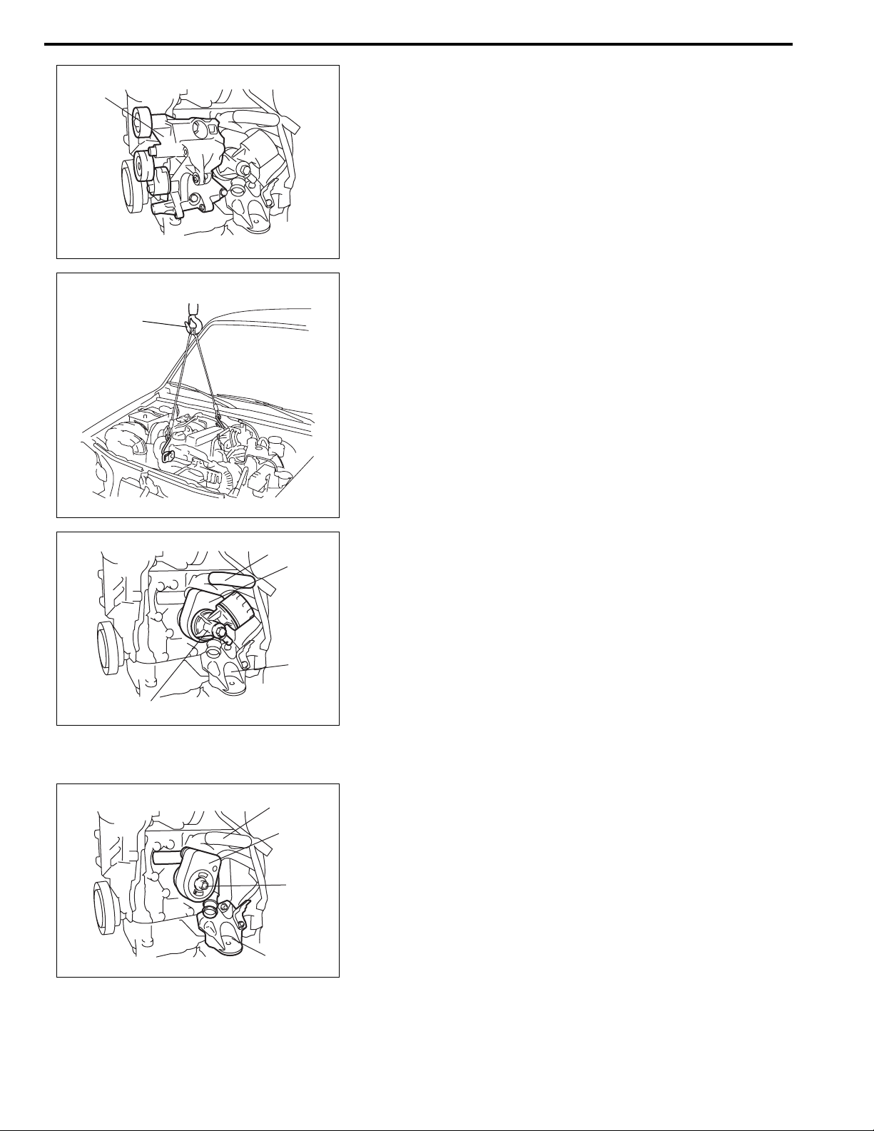
6A2-14 ENGINE MECHANICAL (K9K ENGINE)
1
1
8) Remove compressor bracket (1).
9) Install lifting device (1).
4
3
10) Remove oil filter unit bracket (1).
11) Disconnect heat exchanger hose (4).
12) Remove engine left mounting bracket (2), and then remove
heat exchanger (3).
2
1
Installation
3
1
1) Install heat exchanger (1) with new gasket.
Tightening torque
Heat exchanger bolt (a): 45 N·m (4.5 kg-m, 32.5 lb-ft)
(a)
2) Install engine left mounting bracket (2) referring to “Main
Bearings, Crankshaft and Cylinder Block Removal and
installation” in this section.
3) Connect heat exchanger hose (3).
2
ENGINE MECHANICAL (K9K ENGINE) 6A2-15
4) Install oil filter unit bracket (1) as shown in figure.
NOTE:
(a)
Be sure to align lug (2) of oil filter unit bracket (1) with
hole (3) of heat exchanger (4).
Tightening torque
Oil filter unit bracket bolt (a): 45 N·m (4.5 kg-m, 32.5 lb-ft)
1
2
1
3
4
5) Install generator and compressor bracket (1) referring to
“Generator Drive Belt Tensioner Components” in section
6H2.
6) Install compressor referring to “Compressor” in Section 1B.
7) Install generator referring to “Generator Dismounting and
Remounting” in Section 6H2.
1
8) Connect oil pressure switch connector (1).
9) Install degassing tank to its bracket.
10) Refill engine coolant referring to “Coolant Replacement” in
section 6B2.
11) Check engine oil level referring to “Engine Oil and Filter” in
Section 0B.
12) Check to make sure that there is no oil leakage and coolant
leakage at each connection.
1
6A2-16 ENGINE MECHANICAL (K9K ENGINE)
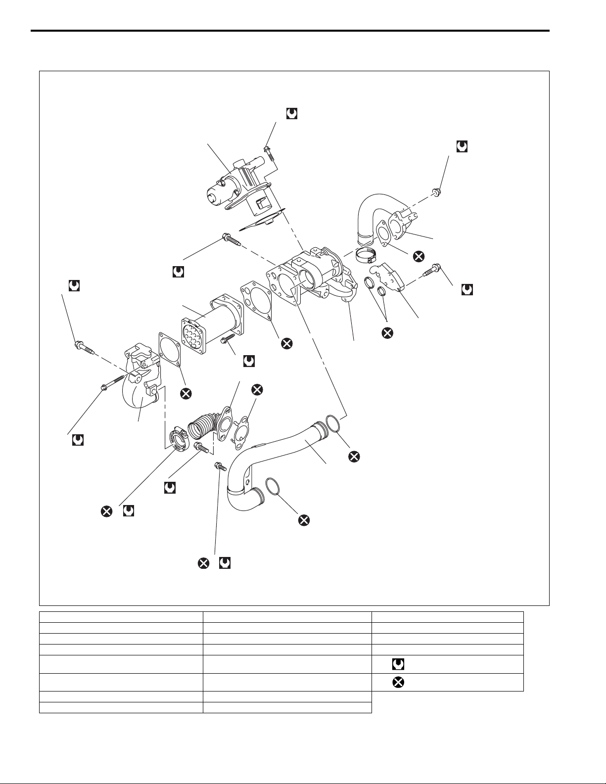
EGR Valve and Intake Pipe Components
14
12 N·m (1.2 kg-m)
16
21 N·m (2.1 kg-m)
17
21 N·m (2.1 kg-m)
3
7
18
10
6
20
10
12
12 N·m (1.2 kg-m)
1
10
10
5
19
15
11 N·m (1.1 kg-m)
12 N·m (1.2 kg-m)
2
12 N·m (1.2 kg-m)
11
4
42 N·m
8
(4.2 kg-m)
5 N·m (0.5 kg-m)
9
20
10N·m (1.0 kg-m)
13
1. EGR pipe 9. EGR pipe clamp 17. EGR valve body bolt
2. EGR cooler pipe 10. Gasket 18. Intake pipe No.1
3. EGR cooler 11. EGR cooler pipe bolt 19. Intake No.1 nut
4. Intake pipe No.2 12. EGR cooler bolt 20. O-ring
5. EGR valve body 13. Intake pipe No.2 bolt Tightening torque
6. EGR cooler water pipe 14. EGR valve bolt
7. EGR valve 15. EGR cooler water pipe bolt
8. EGR pipe bolt 16. EGR cooler pipe bolt
20
Do not reuse.
ENGINE MECHANICAL (K9K ENGINE) 6A2-17
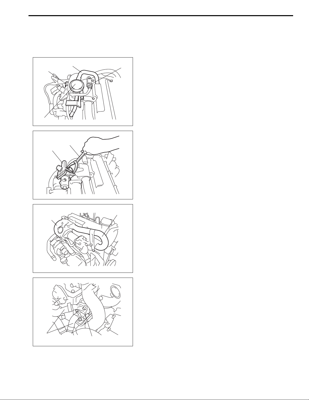
EGR Valve and Intake Pipe Removal and
Installation
Removal
1) Disconnect negative (–) cable at battery .
3
1
2
2) Disconnect EGR valve connector (1) and boost pressure
sensor connector (2).
3) Disconnect hose (3) from oil vapor recirculation valve (4),
and then remove oil vapor recirculation valve.
4
4) Remove EGR valve (1) with gasket using special tool.
(A)
1
Special tool
(A): 09916-48130
2
1
5) Remove intake pipe No.1 (1) and No.2 (2).
6) Disconnect hoses (2) from EGR cooler water pipe (1), and
then remove EGR cooler water pipe.
2
1
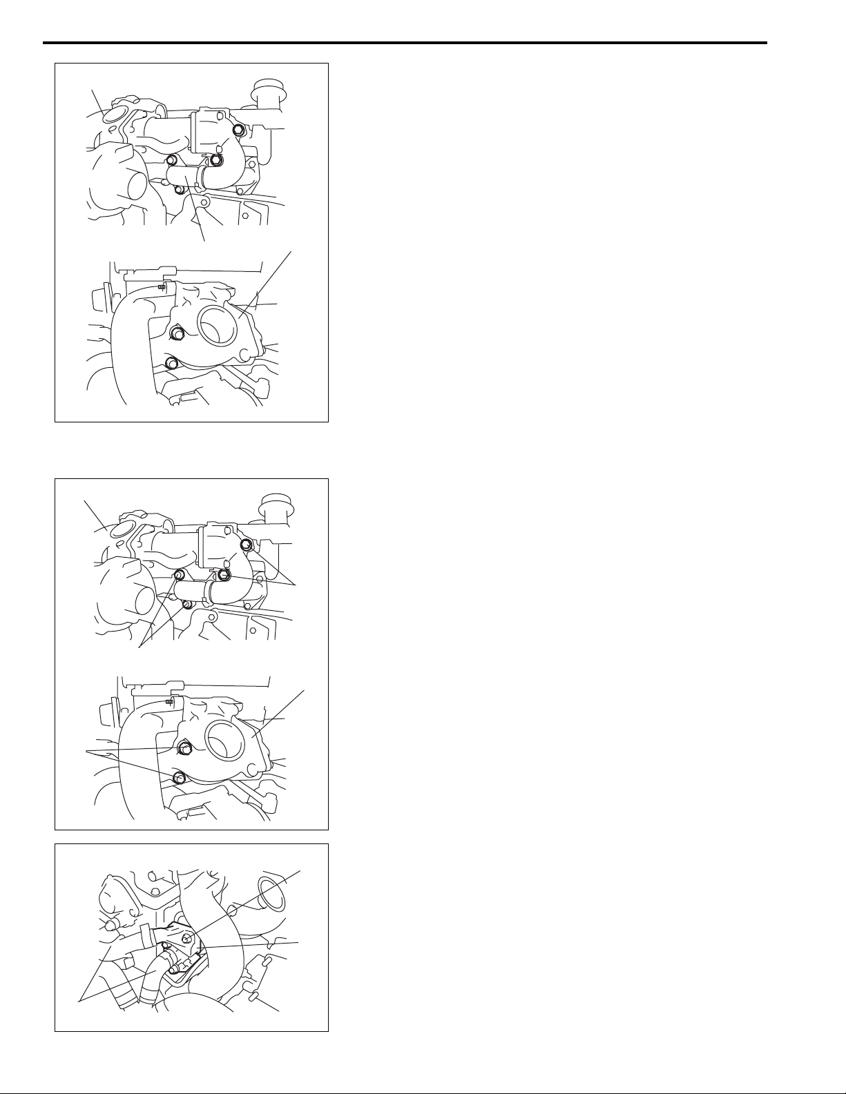
6A2-18 ENGINE MECHANICAL (K9K ENGINE)
1
2
1
7) Remove EGR valve body (1) with EGR pipe (2).
Installation
(c)
1
1) Install EGR valve body assembly (1) with new gasket and
EGR pipe bolt.
Tightening torque
EGR pipe bolt (a): 42 N·m (4.2 kg-m, 30.5 lb-ft)
(b)
EGR cooler pipe bolt (b): 21 N·m (2.1 kg-m, 15.5 lb-ft)
EGR valve body bolt (c): 21 N·m (2.1 kg-m, 15.5 lb-ft)
(a)
1
(a)
2) Install EGR cooler water pipe assembly (1), and then connect hoses (2) to EGR cooler water pipe assembly.
Tightening torque
EGR cooler water pipe assembly bolt (a):
1
2
12 N·m (1.2 kg-m, 9.0 lb-ft)
ENGINE MECHANICAL (K9K ENGINE) 6A2-19
1
2
Tightening torque
Intake pipe No.1 nut: 11 N·m (1.1 kg-m, 8.0 lb-ft)
4) Apply engine oil to new O-ring, and install intake pipe No.2
(2) with new O-ring.
3) Install intake pip e No.1 with new gasket.
(a)
Tightening torque
Intake pipe No.2 bolt (a): 10 N·m (1.0 kg-m, 7.5 lb-ft)
3
2
5) Install EGR valve (1) with new gasket.
Tightening torque
4
EGR valve bolt (a): 12 N·m (1.2 kg-m, 9.0 lb-ft)
6) Install oil vapor recirculation valve (5), and then connect
5
hose (2) to oil vapor recirculation valve.
7) Connect EGR valve connector (3) and boost pressure sensor connector (4).
1
(a)
8) Connect negative (–) cable at battery.
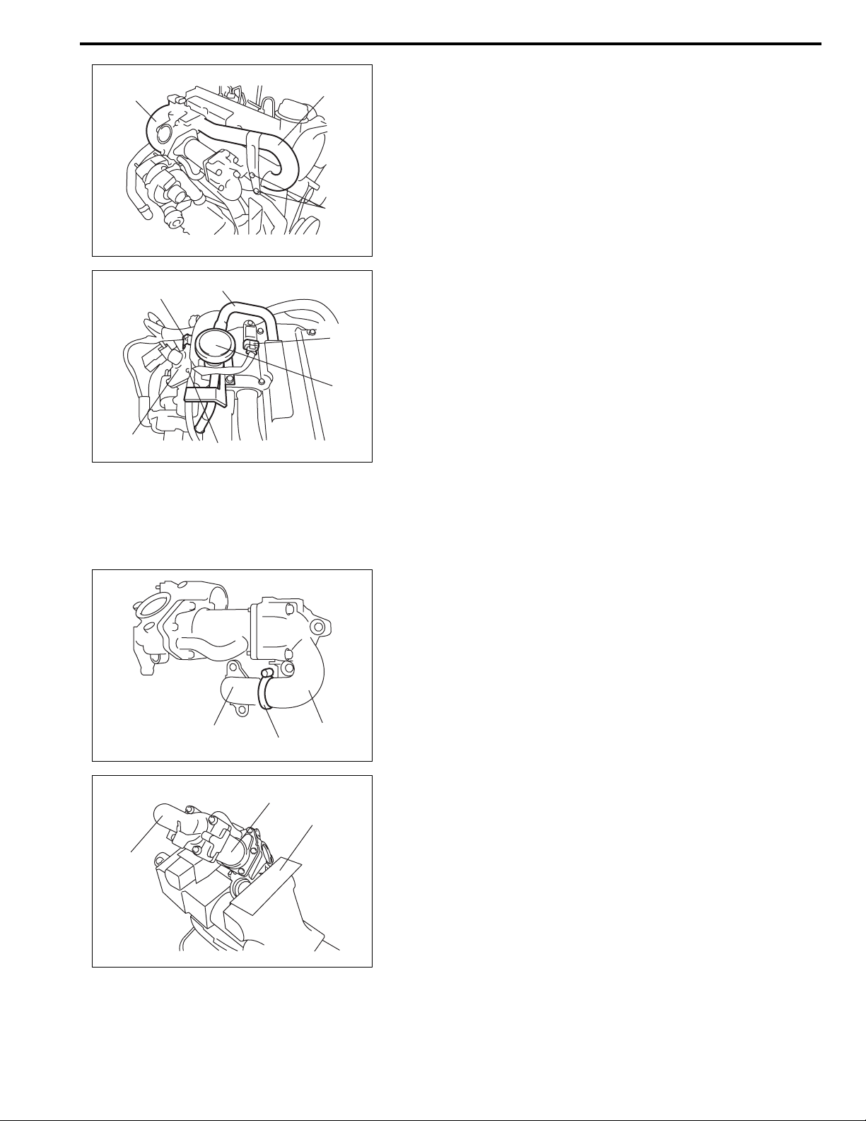
EGR Valve Disassembly and Reassembly
Disassembly
1) Remove clamp (1) and EGR pipe (2) from exhaust gas
cooler pipe (3).
2
1
3
2
3
2) Hold EGR valve body with soft jawed vise (1), and remove
1
exhaust gas cooler (2) with gasket.
3) Remove EGR cooler (3) with gasket.
6A2-20 ENGINE MECHANICAL (K9K ENGINE)
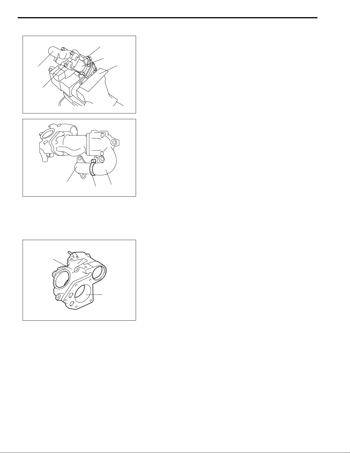
Reassembly
(a)
3
2
1
1) Hold EGR valve body with soft jawed vise (1), and install
EGR cooler (3) with new gasket.
2) Install EGR cooler pipe (2) with new gasket.
Tightening torque
EGR cooler bolt (a): 12 N·m (1.2 kg-m, 9.0 lb-ft)
EGR cooler pipe bolt (b): 12 N·m (1.2 kg-m, 9.0 lb-ft)
(b)
3) Install EGR pipe (1) to EGR cooler pipe (2), and then install
EGR pipe clamp (3).
Tightening torque
EGR pipe clamp (a): 5 N·m (0.5 kg-m, 4.0 lb-ft)
1
3, (a)
2
EGR Valve and Intake Pipe Inspection
EGR valve body
Check inside (1) of EGR valve body (2) for wear or damaged.
2
1
EGR valve
Refer to “EGR Valve Inspection” in Section 6E2.
 Loading...