

Page 1

VYPER
USER’S GUIDE
en
Page 2

Arrows:
- Decompression Stop at the Ceiling Depth
- Mandatory Safety Stop Zone
- Ascent Recommended
- Must Descend
Present Depth
Dive Counter
Logbook Symbol
Dive Attention Symbol
Bar Graph:
- Mode Indicator
- Consumed Botton Time
- Oxygen Limit Fraction
Do Not Fly Icon
Oxygen Percentage in
Nitrox Mode
Altitude Adjustment Mode
Personal Adjustment
Mode
Temperature
Week Day
Mode Text
Indicators for the Scroll
Buttons
Dive Planning Button
Scroll Button (increase value, ascend)
Maximum Depth
Ceiling Depth on Decompression
Mandatory Safety Stop Depth
Average Depth on Logbook
Oxygen Partial Pressure
AM/PM Indicator
Time (alternative display) Button
Scroll Button (decrease value, descend)
Safety Stop Warning
Safety Stop Indicator
Fast Ascent Warning
(SLOW)
Bar Graph:
- Ascent Rate Indicator
- Battery Power Indicator
- Logbook Page Indicator
Current Time Display
Surface Interval Time
No Flying Time
No-Decompression Time
Total Ascent Time
Safety Stop Time
The Smart Button:
- Activation
- Backlight
- Mode Operations
Indicators for the Smart
Button
Low Battery Warning
Dive Time
Time
Month,Day
Daily/DiveTime/Depth
Alarm On Indicator
QUICK REFERENCE GUIDE
Page 3

1. WELCOME TO THE WORLD OF SUUNTO DIVE COMPUTERS .. ... ... ... ... ... 7
2. WARNINGS, CAUTIONS, AND NOTES . ... ... ... ... ... ... . .. . .. . .. . ... ... ... ... ... .. 8
3. SUUNTO USER INTERFACE . .. . .. . .. . ... ... ... ... ... ... ... . .. . .. . .. . ... ... ... ... ... 17
3.1. Navigating in the menus . ... . .. . .. . .. . ... ... ... ... ... ... ... . .. . .. . .. . ... ... ... ... 17
3.2. Button symbols and functions . . .. . ... ... ... ... ... ... ... . .. . .. . .. . ... ... ... ... ... 18
4. GETTING STARTED .. ... ... ... ... ... ... ... . .. . .. . .. . ... ... ... ... ... ... ... . .. . .. . .. . .. 21
4.1. SET MODES [3 SET] . ... . .. . .. . .. . ... ... ... ... ... ... ... . .. . .. . .. . ... ... ... ... ... 25
4.1.1. Setting Time [2 SET TIME] . . .. . .. . .. . ... ... ... ... ... ... ... . .. . .. . ... ... ... . 26
4.1.2. Setting Preferences [3 SET PREF] . .. . .. . .. . ... ... ... ... ... ... ... . .. . .. . . 29
4.2. AC water contacts . ... ... ... . .. . .. . ... ... ... ... ... ... ... . .. . .. . .. . ... ... ... ... ... . 31
5. BEFORE DIVING . ... ... ... . .. . .. . ... ... ... ... ... ... ... ... . .. . .. . ... ... ... ... ... ... ... . 33
5.1. The Suunto RGBM ... ... ... ... . .. . .. . ... ... ... ... ... ... ... . .. . .. . .. . ... ... ... ... . 33
5.2. Emergency ascents . ... ... ... ... ... ... ... . .. . .. . .. . ... ... ... ... ... ... ... . .. . .. . .. 34
5.3. Dive computer limitations ... ... . .. . .. . .. . ... ... ... ... ... ... ... . .. . .. . .. . ... ... ... 34
5.4. Audible and visual alarms . ... ... ... ... . .. . .. . .. . ... ... ... ... ... ... ... . .. . .. . ... . 34
5.5. Error conditions . ... ... ... ... ... . .. . .. . .. . ... ... ... ... ... ... ... . .. . .. . ... ... ... ... . 38
5.6. DIVE mode settings . . .. . ... ... ... ... ... ... ... . .. . .. . ... ... ... ... ... ... ... ... . .. . . 39
5.6.1. Setting the personal/altitude adjustments [1 AdJ MODE] . . .. . ... ... ... 40
5.6.2. Setting the dive-time alarm [2 d ALARM] .. ... ... ... ... . .. . .. . ... ... ... ... 41
5.6.3. Setting the maximum depth alarm [3 MAXDPTH] . .. . ... ... ... ... ... ... . 41
5.6.4. Setting the nitrox values [4 NITROX] . . .. . ... ... ... ... ... ... ... . .. . .. . .. . . 42
5.7. Activation and pre-checks ... ... ... ... . .. . .. . .. . ... ... ... ... ... ... ... . .. . .. . ... .. 43
5.7.1. Accessing DIVE mode ... ... ... ... . .. . .. . ... ... ... ... ... ... ... . .. . .. . .. . ... . 43
5.7.2. DIVE mode activation .. . .. . .. . .. . ... ... ... ... ... ... ... . .. . .. . ... ... ... ... ... 44
3
Page 4

5.7.3. Battery power indication . .. . .. . ... ... ... ... ... ... ... . .. . .. . .. . ... ... ... ... .. 46
5.7.4. Diving at altitude .. ... ... ... ... ... . .. . .. . ... ... ... ... ... ... ... . .. . .. . .. . ... ... 47
5.7.5. Personal adjustments .. . .. . ... ... ... ... ... ... ... . .. . .. . .. . ... ... ... ... ... ... 48
5.8. Safety Stops ... ... ... ... . .. . .. . .. . ... ... ... ... ... ... ... . .. . .. . .. . ... ... ... ... ... ... 50
5.8.1. Recommended Safety Stops ... ... . .. . .. . .. . ... ... ... ... ... ... ... . .. . .. . .. 51
5.8.2. Mandatory Safety Stops . .. . .. . ... ... ... ... ... ... ... . .. . .. . .. . ... ... ... ... .. 52
6. DIVING . ... ... ... ... . .. . .. . .. . ... ... ... ... ... ... ... . .. . .. . .. . ... ... ... ... ... ... ... . .. . .. . 54
6.1. Diving in AIR mode . . ... ... ... ... ... ... ... . .. . .. . .. . ... ... ... ... ... ... ... . .. . .. . .. 54
6.1.1. Basic dive data . ... ... ... . .. . .. . ... ... ... ... ... ... ... ... . .. . .. . ... ... ... ... .. 55
6.1.2. Bookmark . ... . .. . .. . ... ... ... ... ... ... ... ... . .. . .. . ... ... ... ... ... ... ... . .. . . 56
6.1.3. Consumed Bottom Time (CBT) .. ... . .. . .. . ... ... ... ... ... ... ... . .. . .. . .. . . 57
6.1.4. Ascent rate indicator . . .. . .. . ... ... ... ... ... ... ... . .. . .. . .. . ... ... ... ... ... .. 58
6.1.5. Decompression dives . .. . .. . ... ... ... ... ... ... ... ... . .. . .. . ... ... ... ... ... .. 60
6.2. Diving in NITROX mode .. ... ... ... ... ... . .. . .. . .. . ... ... ... ... ... ... ... . .. . .. . .. 67
6.2.1. Before diving in the NITROX mode . ... ... ... ... . .. . .. . ... ... ... ... ... ... . 68
6.2.2. Oxygen displays ... ... ... ... . .. . .. . .. . ... ... ... ... ... ... ... . .. . .. . .. . ... ... .. 69
6.2.3. Oxygen limit fraction (OLF%) ... ... ... . .. . .. . .. . ... ... ... ... ... ... ... . .. . .. 71
6.3. Diving in the GAUGE mode .. .. . ... ... ... ... ... ... ... . .. . .. . ... ... ... ... ... ... .. 73
7. AFTER DIVING ... ... ... ... . .. . .. . ... ... ... ... ... ... ... . .. . .. . .. . ... ... ... ... ... ... ... . . 75
7.1. Surface interval ... ... ... ... . .. . .. . .. . ... ... ... ... ... ... ... . .. . .. . .. . ... ... ... ... .. 75
7.2. Dive numbering . ... ... ... ... ... . .. . .. . .. . ... ... ... ... ... ... ... . .. . .. . ... ... ... ... . 78
7.3. Flying after diving . ... . .. . .. . .. . ... ... ... ... ... ... ... . .. . .. . .. . ... ... ... ... ... ... .. 78
7.4. Memories and Data Transfer [1 MEMORY] ... . .. . .. . ... ... ... ... ... ... ... . .. . . 79
7.4.1. Logbook and Dive Profile Memory [1 LOGBOOK]) . ... ... ... ... ... ... .. 80
4
Page 5

7.4.2. Dive history Memory [2 HISTORY] .. ... ... . .. . .. . .. . ... ... ... ... ... ... ... . 86
7.4.3. Data Transfer and PC-Interface [3 TR-PC] . .. . ... ... ... ... ... ... ... . .. . .. 88
7.5. Movescount . .. . ... ... ... ... ... ... ... ... . .. . .. . ... ... ... ... ... ... ... . .. . .. . .. . ... .. 89
7.6. Simulation Mode [SIMUL] .. ... ... . .. . .. . .. . ... ... ... ... ... ... ... . .. . .. . .. . ... ... . 90
7.6.1. Dive Simulator [1 SIMDIVE] . . .. . .. . ... ... ... ... ... ... ... . .. . .. . ... ... ... .. 91
7.6.2. Dive Planning Simulator [2 SIMPLAN] .. ... ... . .. . .. . .. . ... ... ... ... ... ... 92
8. CARE AND MAINTENANCE OF MY SUUNTO DIVING COMPUTER . . .. . ... .. 94
9. BATTERY REPLACEMENT .. ... ... ... . .. . .. . ... ... ... ... ... ... ... . .. . .. . .. . ... ... ... . 97
9.1. Battery kit . . .. . ... ... ... ... ... ... ... . .. . .. . ... ... ... ... ... ... ... ... . .. . .. . ... ... ... . 97
9.2. Required tools .. . ... ... ... ... ... ... ... . .. . .. . .. . ... ... ... ... ... ... ... . .. . .. . .. . ... . 97
9.3. Replacing the battery .. . .. . .. . .. . ... ... ... ... ... ... ... . .. . .. . ... ... ... ... ... ... ... 98
10. TECHNICAL DATA .. . .. . ... ... ... ... ... ... ... ... . .. . .. . ... ... ... ... ... ... ... . .. . .. . . 102
10.1. Technical specifications . ... ... ... . .. . .. . ... ... ... ... ... ... ... . .. . .. . .. . ... ... . 102
10.2. RGBM . ... ... ... ... . .. . .. . .. . ... ... ... ... ... ... ... . .. . .. . .. . ... ... ... ... ... ... ... 105
10.2.1. Suunto RGBM adaptive decompression . ... ... ... . .. . .. . ... ... ... ... . 106
10.2.2. No-decompression limits for air .. ... ... ... ... ... ... ... . .. . .. . ... ... ... .. 107
10.2.3. Altitude diving ... ... ... ... ... . .. . .. . ... ... ... ... ... ... ... . .. . .. . .. . ... ... .. 109
10.3. Oxygen exposure ... ... ... ... ... . .. . .. . ... ... ... ... ... ... ... ... . .. . .. . ... ... .. 110
11. INTELLECTUAL PROPERTY . ... ... ... ... . .. . .. . .. . ... ... ... ... ... ... ... . .. . .. . ... 112
11.1. Trademark . ... ... ... ... ... ... . .. . .. . .. . ... ... ... ... ... ... ... . .. . .. . .. . ... ... ... . 112
11.2. Copyright . ... . .. . .. . ... ... ... ... ... ... ... ... . .. . .. . ... ... ... ... ... ... ... . .. . .. . .. 112
11.3. Patent notice . ... . .. . .. . ... ... ... ... ... ... ... . .. . .. . .. . ... ... ... ... ... ... ... . .. . 112
12. DISCLAIMERS . . ... ... ... ... ... ... ... . .. . .. . ... ... ... ... ... ... ... ... . .. . .. . ... ... ... 113
12.1. CE . ... ... ... ... ... ... . .. . .. . .. . ... ... ... ... ... ... ... . .. . .. . .. . ... ... ... ... ... ... . 113
5
Page 6

12.2. EN 13319 ... ... ... ... . .. . .. . .. . ... ... ... ... ... ... ... . .. . .. . .. . ... ... ... ... ... ... 113
12.3. EN 250 / FIOH . .. . ... ... ... ... ... ... ... ... . .. . .. . ... ... ... ... ... ... ... . .. . .. . .. 113
13. SUUNTO LIMITED WARRANTY . .. . .. . ... ... ... ... ... ... ... . .. . .. . .. . ... ... ... .. 114
14. DISPOSAL OF THE DEVICE . ... ... ... ... ... . .. . .. . .. . ... ... ... ... ... ... ... . .. . .. . 116
GLOSSARY ... ... ... . .. . .. . ... ... ... ... ... ... ... ... . .. . .. . ... ... ... ... ... ... ... . .. . .. . .. . 117
6
Page 7

1. WELCOME TO THE WORLD OF SUUNTO DIVE COMPUTERS
Suunto Vyper dive computer is designed to help you get the most out of your diving.
The Vyper dive computer is a compact and sophisticated multipurpose dive instrument
that will give you years of trouble-free and joyful diving.
The Suunto Vyper User's Guide contains vitally important information which enables
you to become familiar with your Suunto wristop dive computer. To understand the
use, displays, and limitations of the instrument before using it, please read this user's
guide carefully, and save it for further reference. Note also that a glossary is included
at the back of the user's guide to help you understand dive-specific terminology.
7
Page 8

2. WARNINGS, CAUTIONS, AND NOTES
Throughout this user's guide, important safety icons are displayed. Three classifications
are used to separate these icons by their order of importance:
WARNING
is used in connection with a procedure or situation that may result
in serious injury or death
CAUTION
NOTE
Before you go on to read the user's guide itself, it is extremely important that you read
the following warnings. These warnings are intended to maximize your safety while
using Suunto Vyper and must not be ignored.
WARNING
WARNING
8
is used in connection with a procedure or situation that will result
in damage to the device
is used to emphasize important information
YOU MUST READ the leaflet and user guide for your dive computer. Failure to do so may lead to improper use, serious injury
or death.
ALLERGIC REACTIONS OR SKIN IRRITATIONS MAY OCCUR
WHEN PRODUCT IS IN CONTACT WITH SKIN, EVEN THOUGH
OUR PRODUCTS COMPLY WITH INDUSTRY STANDARDS.
IN SUCH EVENT, STOP USE IMMEDIATELY AND CONSULT
A DOCTOR.
Page 9

WARNING
NOT FOR PROFESSIONAL USE! Suunto dive computers are
intended for recreational use only. The demands of commercial
or professional diving may expose the diver to depths and conditions that tend to increase the risk of decompression illness (DCI).
Therefore, Suunto strongly recommends that the device not be
used for any commercial or professional diving activities.
WARNING
WARNING
ONLY DIVERS TRAINED IN PROPER USE OF SCUBA DIVING
EQUIPMENT SHOULD USE A DIVE COMPUTER! No dive
computer can replace the need for proper dive training. Insufficient
or improper training may cause a diver to commit errors that may
lead to serious injury or death.
THERE IS ALWAYS A RISK OF DECOMPRESSION ILLNESS
(DCI) FOR ANY DIVE PROFILE EVEN IF YOU FOLLOW THE
DIVE PLAN PRESCRIBED BY DIVE TABLES OR A DIVE
COMPUTER. NO PROCEDURE, DIVE COMPUTER OR DIVE
TABLEWILL PREVENT THE POSSIBILITY OF DCI OR OXYGEN
TOXICITY! An individual’s physiological make up can vary from
day to day. The dive computer cannot account for these variations.
You are strongly advised to remain well within the exposure limits
provided by the instrument to minimize the risk of DCI. As an
added measure of safety, you should consult a physician regarding
your fitness before diving.
9
Page 10

WARNING
SUUNTO STRONGLY RECOMMENDS THAT SPORT DIVERS
LIMIT THEIR MAXIMUM DEPTH TO 40 M/130 FT OR TO THE
DEPTH CALCULATED BY THE COMPUTER BASED ON THE
SELECTED O2% AND A MAXIMUM PO2OF 1.4 BAR! Exposure
to greater depths increases the risk of oxygen toxicity and decompression illness.
10
WARNING
WARNING
WARNING
DIVES WITH REQUIRED DECOMPRESSION STOPS ARE NOT
RECOMMENDED. YOU SHOULD ASCEND AND BEGIN DECOMPRESSION IMMEDIATELY WHEN THE DIVE COMPUTER
SHOWS YOU THAT A DECOMPRESSION STOP IS REQUIRED!
Note the blinking ASC TIME symbol and the upward pointing arrow.
USE BACK-UP INSTRUMENTS! Ensure that you use back-up
instrumentation, including a depth gauge, submersible pressure
gauge, timer or watch, and have access to decompression tables
whenever diving with the dive computer.
PERFORM PRE-CHECKS! Always activate and check the device
before diving in order to ensure that all Liquid Crystal Display
(LCD) segments are completely displayed, the device has not
run out of battery power, and that the oxygen, altitude, personal,
and Safety/Deep Stop are correct.
Page 11

WARNING
YOU ARE ADVISED TO AVOID FLYING ANY TIME THE COMPUTER COUNTS DOWN THE NO-FLY TIME. ALWAYS ACTIVATE THE COMPUTER TO CHECK THE REMAINING NO-FLY
TIME PRIOR TO FLYING! Flying or traveling to a higher altitude
within the no-fly time can greatly increase the risk of DCI. Review
the recommendations given by Divers Alert Network (DAN). There
can never be a flying after diving rule that is guaranteed to completely prevent decompression illness!
WARNING
THE DIVE COMPUTER SHOULD NEVER BE TRADED OR
SHARED BETWEEN USERS WHILE IT IS IN OPERATION! Its
information will not apply to someone who has not been wearing
it throughout a dive or sequence of repetitive dives. Its dive profiles
must match that of the user. If it is left on the surface during any
dive, the dive computer will give inaccurate information for subsequent dives. No dive computer can take into account dives
made without the computer. Thus, any diving activity up to four
days prior to initial use of the computer may cause misleading
information and must be avoided.
11
Page 12

WARNING
THE DIVE COMPUTER WILL NOT ACCEPT FRACTIONAL
PERCENTAGE VALUES OF OXYGEN CONCENTRATION. DO
NOT ROUND UP FRACTIONAL PERCENTAGES! For example,
31.8% oxygen should be entered as 31%. Rounding up will cause
nitrogen percentages to be understated and will affect decompression calculations. If there is a desire to adjust the computer to
provide more conservative calculations, use the personal adjustment feature to affect decompression calculations or reduce the
PO2setting to affect oxygen exposure according to the entered
O2% and PO2values.
12
WARNING
SET THE CORRECT ALTITUDE ADJUSTMENT MODE! When
diving at altitudes greater than 300 m/1000 ft, the Altitude Adjustment feature must be correctly selected in order for the computer
to calculate the decompression status. The dive computer is not
intended for use at altitudes greater than 3000 m/10000 ft. Failure
to select the correct Altitude Adjustment setting or diving above
the maximum altitude limit will result in erroneous dive and planning data.
Page 13

WARNING
SET THE CORRECT PERSONAL ADJUSTMENT MODE!
Whenever it is believed that factors that tend to increase the
possibility of DCI exist, it is recommended that you use this option
to make the calculations more conservative. Failure to select the
correct Personal Adjustment setting will result in erroneous dive
and planning data.
WARNING
WARNING
DO NOT EXCEED THE MAXIMUM ASCENT RATE! Rapid ascents increase the risk of injury. You should always make the
Mandatory and Recommended Safety Stops after you have exceeded the maximum recommended ascent rate. If this Mandatory
Safety Stop is not completed the decompression model will penalize your next dive(s).
YOUR ACTUAL ASCENT TIME MAY BE LONGER THAN DISPLAYED BY THE INSTRUMENT! The ascent time will increase
if you:
• remain at depth
• ascend slower than 10 m/min / 33 ft/min or
• make your decompression stop deeper than at the ceiling
These factors will also increase the amount of air required to
reach the surface.
13
Page 14

WARNING
NEVER ASCEND ABOVE THE CEILING! You must not ascend
above the ceiling during your decompression. In order to avoid
doing so by accident, you should stay somewhat below the ceiling.
14
WARNING
WARNING
WARNING
DO NOT DIVE WITH A CYLINDER OF ENRICHED AIR IF YOU
HAVE NOT PERSONALLY VERIFIED ITS CONTENTS AND
ENTERED THE ANALYSIS VALUE INTO YOUR DIVE COMPUTER! Failure to verify cylinder contents and enter the appropriate O2% into your dive computer will result in incorrect dive
planning information.
DO NOT DIVE WITH A GAS IF YOU HAVE NOT PERSONALLY
VERIFIED ITS CONTENTS AND ENTERED THE ANALYZED
VALUE INTO YOUR DIVE COMPUTER! Failure to verify cylinder
contents and enter the appropriate gas values where applicable
into your dive computer will result in incorrect dive planning information.
Diving with gas mixtures exposes you to risks that are different
from those associated with diving with standard air. These risks
are not obvious, and require training to understand and avoid.
Risks include possible serious injury or death.
Page 15

WARNING
Traveling to a higher elevation can temporarily cause a change
in the equilibrium of dissolved nitrogen in the body. It is recommended that you acclimatize to the new altitude by waiting at
least three hours before diving.
WARNING
WARNING
WARNING
WHEN THE OXYGEN LIMIT FRACTION INDICATES THAT THE
MAXIMUM LIMIT IS REACHED, YOU MUST IMMEDIATELY
TAKE ACTION TO REDUCE OXYGEN EXPOSURE. Failure to
take action to reduce oxygen exposure after the warning is given
can rapidly increase the risk of oxygen toxicity, injury, or death
Suunto also recommends that you receive training in Free diving
techniques and physiology before conducting breath hold dives.
No dive computer can replace the need for proper dive training.
Insufficient or improper training may cause a diver to commit errors
that may lead to serious injury or death.
Using the Suunto Dive Planner software is not a substitute for
proper dive training. Diving with mixed gases has dangers that
are not familiar to divers diving with air. To dive with trimix, triox,
heliox and nitrox or all of them, divers must have specialized
training for the type of diving they are doing.
15
Page 16

WARNING
Always use realistic SAC rates and conservative turn pressures
during dive planning. Overly optimistic or erroneous gas planning
can result in the exhaustion of breathing gas during decompression or in a cave or a wreck.
WARNING
NOTE
In GAUGE mode the no-fly time is always 48 hours.
16
ENSURE THE WATER RESISTANCEOF THE DEVICE! Moisture
inside the device or battery compartment will seriously damage
the unit. Only an authorized SUUNTO dealer or distributor should
do service activities.
It is not possible to change between AIR, NITROX and GAUGE
modes before the instrument has counted down the no-fly time.
There is one exception to this: You can change from AIR to NITROX mode even during the no-fly time.
Page 17

3. SUUNTO USER INTERFACE
3.1. Navigating in the menus
Suunto Vyper multipurpose dive computer features three dive computer modes (AIR,
NITROX, GAUGE), three main operating modes (TIME/STAND-BY, SURFACE,
DIVING), three menu based main modes (MEMORY, SIMULATION, SET) and 15–17
menu based submodes. You can scroll through the modes using the push buttons.
The mode indicator at the left side and the mode text at the bottom of the display indicate the selected mode.
The timekeeping display is the primary display of the instrument. In other modes (except
in the Diving or Simulator modes), if no button is operated within 5 minutes, the dive
computer beeps and returns to the timekeeping display automatically. The timekeeping
display shuts off after two hours, but pressing the PLAN or TIME button activates it.
When diving, the dive entry time and date is registered in the Logbook Memory. Remember always to check before diving that the time and date are correctly set, especially when traveling to different time zones.
17
Page 18

Figure 3.1. Time keeping display. Press the PLAN or TIME button to activate the
display.
3.2. Button symbols and functions
The list below explains the main functions of the dive computer's buttons. The buttons
and their use is explained in more detail in the relevant sections of the user's guide.
The dive computer has easy-to-use push buttons and an advising display, which guides
the user. The SMART (MODE) button is the key of the system. The two scroll buttons,
PLAN and TIME, are used for scrolling up and down the menus and to get the alternative displays visible. The dive computer is controlled with these three push buttons
as follows.
18
Page 19

Figure 3.2. Push buttons of the dive computer.
SMART (MODE) button
Activates the dive computer
•
Switches from the Surface mode to menu based modes
•
Selects, confirms or quits a submode (short press)
•
Immediately exits any submode to the Surface mode (long press)
•
Activates the electroluminescent backlight (in the Surface mode hold down the
•
mode button for more than two (2) seconds, during a dive for one (1) second).
PLAN (arrow up) button
Activates the timekeeping display, if the display is blank.
•
Activates the Dive Planning in the Surface mode
•
Makes a special bookmark in the profile memory during a dive
•
Scrolls up the options ( increases values)
•
TIME (arrow down) button
Activates the timekeeping display, if the display is blank.
•
19
Page 20

Activates the Time display(s) and/or alternative display(s).
•
Scrolls down the options ( decreases values)
•
The dive computer is controlled with the SMART (MODE/On/Backlight/Select/
OK/Quit) and the PLAN and TIME push buttons and with the water contacts as
follows:
Activation: Press the SMART (On) button or immerse the instrument in water for five
(5) seconds.
Dive Planning: In the Surface mode, press the PLAN button.
Menu modes: Press the SMART (MODE) button.
The display is illuminated by holding down the SMART button for more than two
seconds.
20
Page 21

4. GETTING STARTED
To get the most out of your Suunto Vyper , use some time to personalize it and really
make it YOUR computer. Set the correct time and date, the alarms, and backlight
settings.
The main menu based functions are grouped under 1) memory, 2) dive simulation
and 3) setting modes. User options for the Vyper are selected by using the push buttons. Pre Dive configuration and setup options include:
• Choice of operating mode - Air / Nitrox / Gauge
• Maximum depth alarm
• Dive time alarm
• Backlight settings
• Clock, calendar, daily alarm
• Mix Oxygen fraction % (Nitrox mode only)
• Maximum PO2 (Nitrox mode only)
• Altitude adjustment
• Personal adjustment
These options are introduced in more detail in Section 4.1. SET MODES [3 SET].
THE LIST OF THE MENU BASED MODES
1. MEMORIES AND DATA TRANSFER [1 MEMORY]
• Logbook and Dive Profile Memory [1 LOGBOOK]
• Dive History Memory [2 HISTORY]
• Data Transfer and PC-Interface [3 TR-PC]
2. SIMULATION MODE [2 SIMUL]
• Dive Simulator [1 SIMDIVE]
21
Page 22

• Dive Planning Simulator [2 SIMPLAN]
3. SET MODES [3 SET]
• Dive Parameter Settings [1 SETDIVE]
• Altitude Adjustment and Personal Adjustment Settings [1 AdJ MODE]
• Dive Time Alarm Setting [2 d ALARM]
• Maximum Depth Alarm Setting [3 MAX DPTH]
• Nitrox/Oxygen Settings [4 NITROX]
• Setting Time [2 SET TIME]
• Adjusting Time [1 AdJ TIME]
• Adjusting Date [2 AdJ DATE]
• Adjusting Daily Alarm [3 T ALARM]
• Setting Preferences [3 SET PREF]
• Backlight Setting [1 LIGHT]
• Dive Computer Model Setting [2 MODEL]
NOTE
Memories and Data Transfer modes and Simulation Modes are introduced in
Section 7.4. Memories and Data Transfer [1 MEMORY]
and Section 7.6. Simulation Mode [SIMUL].
Dive parameter settings are introduced in Section 5.6. DIVE mode settings.
22
The menu based modes cannot be activated until 5 minutes after
the dive.
Page 23

THE USE OF THE MENU BASED FUNCTIONS
1. Activate the menu based modes by pressing once the SMART (MODE) button
in the Dive Mode.
Figure 4.1. Main menu based Mode options [3 MODE]
2. Scroll the mode options by pressing the arrow up/ down buttons. When scrolling
the options, the label and an equivalent number are shown on the display.
23
Page 24

Figure 4.2. Scroll the mode options by pressing the arrow up/ down buttons.
3. Press the SMART (Select) button once to select the desired option.
4. Scroll the submode options by pressing the arrow up/down buttons. When scrolling
the options, the label and an equivalent number are shown on the display.
5. Select the desired option by pressing once the SMART (Select) button. Repeat
the procedure, if there are more submodes.
6. Depending on the mode, you are now able to have a look at the memories, simulate a dive, or make desired settings (use the the arrow up/down buttons). The
SMART button is used to Quit or to confirm the settings (OK).
NOTE
24
If you do not press any of the buttons for 5 minutes while in
a Menu based mode, the instrument beeps and returns to
the timekeeping display. In the Simulation Mode, however,
the equivalent time is 60 minutes.
Page 25

By pressing the SMART button for more than 1 second, any menu based function
or submode can be quit and the dive computer will return directly to the Dive
Mode.
4.1. SET MODES [3 SET]
The Set Modes include dive configuration and setup options that have to be set before
the dive. The Set Modes are divided into three submodes for setting the dive-related
parameters, time related parameters and your personal preferences. In this section
are introduced the time related parameters (Setting Time [2 SET TIME]) and personal
preferences (Setting Preferences [3 SET PREF]). The dive-related parameters ( Dive
Parameter Settings [1 SET DIVE]) are introduced in more detail in Section 5.6. DIVE
mode settings.
Figure 4.3. Setting Options [3 SET]
25
Page 26

4.1.1. Setting Time [2 SET TIME]
To enter the Time Setting mode, select MODE- 3 SET- 2 SET TIME. The Time Setting
mode has three options: 1 AdJ Time, 2 AdJ Date, and 3 T ALARM Daily Time Alarm.
Figure 4.4. Time Setting Mode [2 SET TIME]
Adjusting Time [1 AdJ TIME]
To enter the Time Setting mode, select MODE- 3 SET- 2 SET TIME- 1 AdJ TIME.
After entering this mode you are able to select between 12 h and 24 hour time formats
and set the correct time by using the SMART (MODE) and scroll buttons.
26
Page 27

Figure 4.5. Adjusting the Time setting.
Adjusting Date [2 AdJ DATE]
To enter the Date Setting mode, select MODE- 3 SET- 2 SET TIME- 2 AdJ DATE.
After entering this mode you are able to set the correct year, month and day in this
order.
NOTE
The day of the week is automatically calculated in accordance
with the date. The date can be set within the range of Jan 1, 1990
to Dec. 31, 2089.
27
Page 28

Figure 4.6. Adjusting the Date setting mode [2 AdJ DATE].
Adjusting Daily Alarm [3 T ALARM]
You can set one daily alarm in the dive computer. When the daily alarm activates, the
time symbol blinks for 1 minute and the alarm sounds for 24 seconds. The alarm is
given at the preset time each day. Press any button to stop the audible alarm, after it
has activated.
To enter the Daily Alarm Setting mode, select MODE- 3 SET- 2 SET TIME- 3 T ALARM.
After entering this mode you are able to set the desired alarm time.
28
Page 29

Figure 4.7. Adjusting the Daily Alarm setting mode [3 T ALARM]
4.1.2. Setting Preferences [3 SET PREF]
To enter the Setting Preferences mode, select MODE- 3 SET- 3 SET PREF. The
Setting Preferences mode has two options: 1 LIGHT and 2 MODEL.
Backlight On Time Setting [1 LIGHT]
In the Backlight Setting mode the backlight can be turned off or on and the on time
can be set to be 5 to 30 seconds.
To enter the Backlight Setting mode, select MODE- 3 SET- 3 SET PREF- 1 LIGHT.
After entering this mode you are able to set the desired backlight on time and to turn
the backlight off or on.
29
Page 30

Figure 4.8. Setting Backlight On Time. Press scroll buttons to change backlight on/off
and to set time value.
Dive Computer Model Settings (Air/Nitrox/Gauge) [3 MODEL]
In the Dive Computer Model Setting mode the dive computer can be set to be an AIR
computer, NITROX computer or a depth GAUGE with a timer.
To enter the Dive Computer Model Setting mode, select MODE- 3 SET- 3 SET PREF3 MODEL.
30
Page 31

Figure 4.9. Setting Dive Computer model
4.2. AC water contacts
The water contacts control the automatic activation of the Dive Mode.
The water and data transfer contacts are located on bottom of the case. When sub-
merged the water contacts are connected to the push buttons (which are the other
pole of the water contact) by the conductivity of the water. The “AC” text will appear
on display. The AC text will be shown until the water contact deactivates or the dive
computer enters the Dive Mode automatically.
31
Page 32

Figure 4.10. Depth sensor (A), water/data transfer contacts (B)
32
Page 33

5. BEFORE DIVING
Do not attempt to use the dive computer without reading this user's guide in its entirety,
including all the warnings. Make sure that you fully understand the use, displays and
limitations of the instrument. If you have any questions about the manual or the dive
computer, contact your SUUNTO dealer before diving with the dive computer.
Always remember that YOU ARE RESPONSIBLE FOR YOUR OWN SAFETY!
When used properly, Suunto Vyper is an outstanding tool for assisting properly trained,
certified divers in planning and executing . It is NOT A SUBSTITUTE FOR CERTIFIED
SCUBA INSTRUCTION, including training in the principles of decompression.
Do not attempt to dive with any gas mix other than standard air without first receiving
certified training in this specialty.
5.1. The Suunto RGBM
Suunto’s Reduced Gradient Bubble Model (RGBM), utilized in the Suunto Vyper,
predicts both dissolved and free gas in the blood and tissues of divers. It is a significant
advance on the classic Haldane models, which do not predict free gas. The advantage
of Suunto RGBM is additional safety through its ability to adapt to a variety of situations
and dive profiles.
In order to optimize the response to different increased risk situations, an additional
category of stop, referred to as a Mandatory Safety Stop, has been introduced. The
combination of stop types depends on the user settings and the specific dive situation.
To get the most from the RGBM safety benefits, refer to Section 10.2. RGBM.
33
Page 34

5.2. Emergency ascents
In the unlikely event that the dive computer malfunctions during a dive, follow the
emergency procedures provided by your certified dive training agency or, alternatively,
follow these steps:
Assess the situation calmly and then move promptly to less than 18 m/60 ft.
1.
At 18 m/60 ft, slow down your ascent rate to 10 m/33 ft per minute and move to
2.
a depth between 3 and 6 m/10 and 20 ft.
Stay there for as long as your air supply will safely allow. After reaching the sur-
3.
face, do not dive for at least 24 hours.
5.3. Dive computer limitations
While the dive computer is based on current decompression research and technology,
you must realize that the computer cannot monitor the actual physiological functions
of an individual diver. All decompression schedules currently known to the authors,
including the U.S. Navy Tables, are based on theoretical mathematical models, which
are intended to serve as a guide to reduce the probability of decompression illness.
5.4. Audible and visual alarms
The dive computer has audible and visual alarms that advise when important limits
are approached or that prompt you to acknowledge preset alarms. The table below
describes the different alarms and their meanings.
The visual information on the dive computer display is shown during the alarm breaks
in order to save battery.
34
Page 35

Table 5.1. Audible and visual alarm types
Dive computer is activated.Short single beep
Dive computer automatically returns to the TIME mode.
Three single beeps with a two
second interval and activated
backlight for five (5) seconds
Continuous beeps and activated backlight for five (5)
seconds
No-decompression dive turns into a decompression
stop dive. An arrow pointing upwards and the blinking
ascent warning ASC TIME appears.
Maximum allowed ascent rate, 10 m per min/33 ft per
min, is exceeded. A SLOW and STOP warnings appears.
The Mandatory Safety Stop ceiling is exceeded. A
downward pointing arrow appears.
Decompression ceiling depth is exceeded. An error
warning Er and a downward pointing arrow appear.
You should immediately descend to, or below, the
ceiling. The instrument will otherwise enter a permanent Error mode within three minutes, indicated by a
permanent Er.
Alarm reasonAlarm type
35
Page 36

Table 5.2. Preset alarm types
Continuous beep series for 24 seconds or until any
button is pressed.
Maximum depth blinks as long as the current depth
value exceeds the preset value.
Continuous beep series for 24 seconds or until any
button is pressed.
Dive time blinks for one minute if no button is pressed.
button is pressed.
Current time blinks for one minute if no button is
pressed.
36
Alarm reasonAlarm type
Preset maximum depth has
been exceeded.
Preset dive time has been exceeded.
Preset alarm time is reached.Continuous beep series for 24 seconds or until any
Page 37

Table 5.3. Oxygen alarms in NITROX mode
Three double beeps and the
backlight for five (5) seconds
Continuous beeps for three (3)
minutes and activated backlight for five (5) seconds
The OLF bar graph reaches 80%. The segments exceeding the 80% limit start to blink.
The OLF bar graph reaches 100%. The OLF value
will blink. The blinking of the segments exceeding 80%
will stop, when the OLF is not loading anymore. At
that point the PO2 is less than 0.5 bar.
Set oxygen partial pressure limit is exceeded. The alternative display is replaced with a current blinking
PO2value. You should immediately ascend above the
PO2depth limit.
Alarm reasonAlarm type
NOTE
WARNING
When the backlight is turned OFF, it does not illuminate when an
alarm is activated.
WHEN THE OXYGEN LIMIT FRACTION INDICATES THAT THE
MAXIMUM LIMIT IS REACHED, YOU MUST IMMEDIATELY
TAKE ACTION TO REDUCE OXYGEN EXPOSURE. Failure to
take action to reduce oxygen exposure after the warning is given
can rapidly increase the risk of oxygen toxicity, injury, or death.
37
Page 38

5.5. Error conditions
The dive computer has warning indicators that alert you to react to certain situations
that would significantly increase the risk of DCI. If you do not respond to its warnings,
the dive computer will enter an Error mode, indicating that the risk of DCI has greatly
increased. If you understand the dive computer and operate it sensibly, it is very unlikely
you will ever put the instrument into the Error mode.
Omitted decompression
The Error mode results from omitted decompression, for example, when you stay
above the ceiling for more than three minutes. During this three-minute period the Er
warning is shown and the audible alarm beeps. After this, the dive computer enters a
permanent Error mode. The instrument will continue to function normally if you descend
below the ceiling within this three-minute period.
When the dive computer is in the permanent Error mode, only the Er warning is shown
in the center window. The dive computer does not show times for ascent or stops.
However, all the other displays function as before to provide information for ascent.
You must immediately ascend to a depth of 3 to 6 m/10 to 20 ft and remain at this
depth until air supply limitations require you to surface.
After surfacing, you should not dive for a minimum of 48 hours. During the permanent
Error mode, the Er text is displayed in the center window and the planning mode is
disabled.
38
Page 39

5.6. DIVE mode settings
Suunto Vyper has several user-definable functions, as well as depth and time-related
alarms that you can set according to your personal preferences. The DIVE mode
settings are dependent on the dive submode chosen (AIR, NITROX, GAUGE), so that,
for example, settings are only available in the submode.
The Set Modes [3 SET] include dive configuration and setup options that have to be
set before the dive. The Set Modes are divided into three submodes for setting the
dive-related parameters, time related parameters and your personal preferences.
Time related parameters [2 SET TIME] and personal preferences [3 SET PREF] are
introduced in Section 4.1. SET MODES [3 SET].
To enter the Dive Parameter Setting Mode, select MODE- 3 SET- 1 SET DIVE. The
Dive Parameter Setting mode [1 SET DIVE] has two to four options depending on the
dive computer mode. In Gauge mode there are two options, in Air mode three options,
and in Nitrox mode four options.
The figure below shows how to enter the DIVE mode settings menu.
NOTE
Some settings cannot be changed until five (5) minutes has
elapsed after the dive.
39
Page 40

5.6.1. Setting the personal/altitude adjustments [1 AdJ MODE]
The current Altitude and Personal Adjustment settings are displayed in the startup
screen when diving at the surface. If the mode does not match the altitude or personal
conditions (refer to Section 5.7.4. Diving at altitude and Section 5.7.5. Personal adjust-
ments), it is imperative that you enter the correct selection before diving. Use Altitude
Adjustment to select the correct altitude and use Personal Adjustment to add an extra
level of conservatism.
To enter the Altitude Adjustment and Personal Adjustment Setting mode, select MODE3 SET- 1 SET DIVE- 1 AdJ MODE. Now you are able to select from the three altitude
modes and the three personal modes.
Figure 5.1. Setting Altitude adjustment and Personal adjustment. Press the scroll
buttons to change the altitude mode.
40
Page 41

5.6.2. Setting the dive-time alarm [2 d ALARM]
The Dive Time Alarm setting [2 d ALARM] can be activated and used for several purposes to add to your diving safety.
To enter the Dive Time Alarm Setting mode, select MODE- 3 SET- 1 SET DIVE- 2 d
ALARM.
Figure 5.2. Setting Dive Time Alarm. Press scroll buttons to change alarm on/off and
to set dive time value.
NOTE
5.6.3. Setting the maximum depth alarm [3 MAXDPTH]
The depth alarm is set to 40 m [131 ft] at the factory, but you are able to adjust it according your personal preference or switch it off. The depth range can be set from 3.0
m to 100 m [9 ft to 328 ft].
With a range of 1–999 minutes, the alarm can be set to your
planned bottom time, for example.
41
Page 42

To enter the Maximum Depth Alarm Setting, select MODE- 3 SET- 1 SET DIVE- 3
MAXDPTH.
Figure 5.3. Setting Maximum Depth Alarm. Press scroll buttons to change alarm on/off
and to set maximum depth value.
5.6.4. Setting the nitrox values [4 NITROX]
If set to the NITROX mode, the correct oxygen percentage of the gas in your cylinder
must always be entered into the computer to ensure correct nitrogen and oxygen
calculations. In addition, the oxygen partial pressure limit must be set. When in the
NITROX setting mode, the maximum operating depth (MOD), based on the chosen
setting, will also be displayed.
To enter the Nitrox/Oxygen Setting mode, select MODE- 3 SET- 1 SET DIVE- 4 NITROX. The default oxygen percentage (O2%) setting is 21% (air) and oxygen partial
pressure (PO2) setting 1.4 bar.
42
Page 43

Figure 5.4. Setting Oxygen Percentage and Partial Pressure. The equivalent maximum
depth is displayed as 32.8 m /107 ft. Press scroll buttons to change oxygen percentage
and to set oxygen partial setting value.
5.7. Activation and pre-checks
This section describes how to activate the DIVE mode and explains the pre-checks
that it is highly recommended you perform before you get into the water.
5.7.1. Accessing DIVE mode
The Suunto Vyper has three diving modes: AIR mode for diving with standard air only,
NITROX mode for diving with oxygen enriched mixtures, and GAUGE mode for use
as a bottom timer.
43
Page 44

5.7.2. DIVE mode activation
The dive computer activates automatically when submerged deeper than 0.5 m/1.5
ft. However, it is necessary to activate the DIVE mode BEFORE diving to check
the altitude and personal adjustment settings, battery condition, oxygen settings,
and so on. Press the SMART (On) button to activate the instrument.
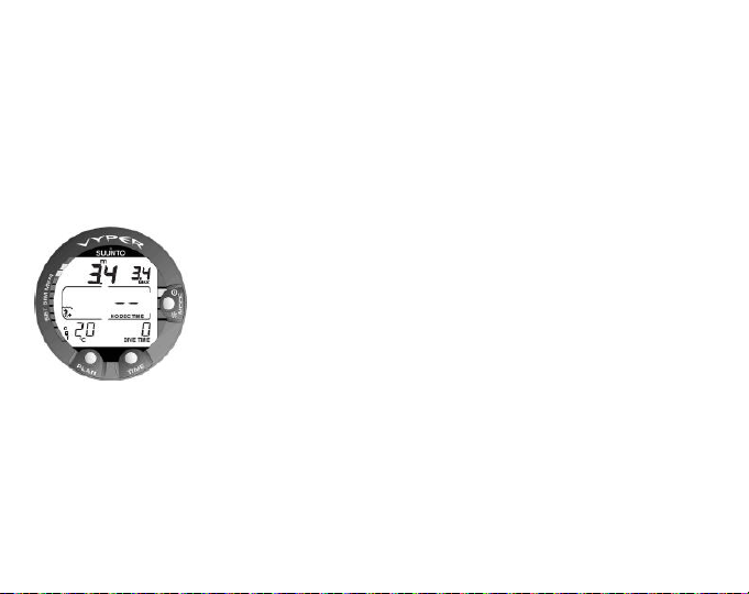
Figure 5.5. Startup I. All segments shown.
After activation, all display elements will turn on showing mostly figure 8’s and graphical elements. A few seconds later the battery power indicator is shown, and the
backlight and the buzzer are activated. If set to Air mode, the screen will enter the
Surface mode. If set to Gauge mode, the text GAUGE is shown, and if set to Nitrox
mode, the essential oxygen parameters are shown with the text "NITROX" before the
Surface mode.
44
Page 45
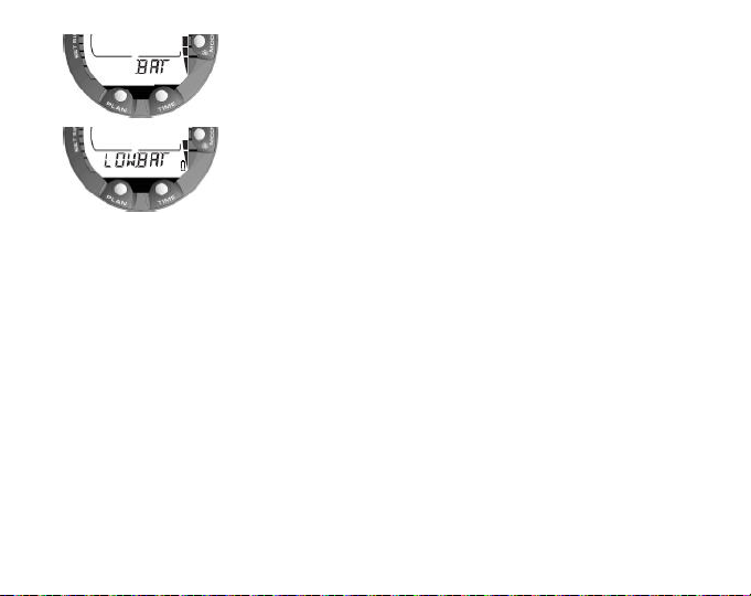
Figure 5.6. Startup II. Battery power indicator.
At this time, perform your pre-checks, and ensure that:
the instrument operates in the correct mode and provides a complete display
•
(AIR/NITROX/GAUGE mode)
the low battery indicator is not on.
•
the altitude and personal adjustment settings are correct.
•
the instrument displays correct units of measurement (Metric/Imperial).
•
the instrument displays the correct temperature and depth (0.0 m/0 ft).
•
the buzzer beeps
•
And, if set to NITROX mode, ensure that:
the oxygen percentage is adjusted according to the measured enriched air blend
•
in your cylinder
the oxygen partial pressure limit is set correctly
•
The dive computer is now ready for diving.
45
Page 46

NOTE
After activation of the Dive mode or after the dive has ended, the instrument will
automatically switch to show the time keeping display within 5 minutes to conserve
the battery power, unless you press any buttons or start a dive.
5.7.3. Battery power indication
This dive computer has a unique graphic Battery Power Indicator designed to give
you an advance notice of impending need to change the battery. The Battery Power
Indicator can always be seen when the Dive mode is activated. The electroluminescent
backlight will be on during the battery check. The following Table and Figure show the
various warning levels.
Temperature or internal oxidation of the battery affect the battery voltage. If the instrument is stored for a long period, or used in cold temperatures, the low battery warning
may be displayed even though the battery has enough capacity. In these cases, reenter DIVE mode to receive the battery power indication.
After the battery check, the low battery warning is indicated by the battery symbol.
46
The surface interval time is not shown before the first dive.
Page 47

Figure 5.7. Low Battery Warning. Battery symbol indicates that the battery is low and
battery replacement is recommended.
If the battery symbol is displayed in the Surface mode, or if the display is faded or
weak, the battery may be too low to operate the dive computer, and battery replacement
is recommended.
NOTE
5.7.4. Diving at altitude
The dive computer can be adjusted both for diving at altitude and also to increase the
conservatism of the mathematical nitrogen model.
When programming the instrument for the correct altitude, you need to select the
correct Altitude Adjustment settings according to Table 5.4, Altitude Adjustment settings.
The dive computer will adjust its mathematical model according to the entered altitude
setting, giving shorter no-decompression times at higher altitudes.
For safety reasons, the backlight cannot be activated when the
low battery warning is indicated by the battery symbol.
47
Page 48

Table 5.4. Altitude Adjustment settings
value
Altitude rangeSymbol on displayAlt. adjustment
0–300 m / 0–1000 ftA0
300–1500 m / 1000–5000 ftA1
1500–3000 m / 5000–10 000 ftA2
NOTE
WARNING
5.7.5. Personal adjustments
There are personal factors that can affect your susceptibility to DCI, which you can
predict in advance, and input into the decompression model. Such factors vary between
divers and also for the same diver from one day to another. There is available a threestep Personal Adjustment setting if a more conservative dive plan is desired, and a
two-step adjustment for RGBM effect on repetitive dives for very experienced divers.
48
Section 5.6.1. Setting the personal/altitude adjustments [1 AdJ
MODE] describes how the Altitude value is set.
Traveling to a higher elevation can temporarily cause a change
in the equilibrium of dissolved nitrogen in the body. It is recommended that you acclimatize to the new altitude by waiting at
least three (3) hours before diving.
Page 49

The personal factors which tend to increase the possibility of DCI include, but are not
limited to:
cold exposure —water temperature less than 20 °C/68 °F
•
below average physical fitness level
•
fatigue
•
dehydration
•
previous history of DCI
•
stress
•
obesity
•
patent foramen ovale (PFO)
•
exercise on or after dive
•
This feature is used to adjust the computer to be more conservative, according to
personal preference, by entering the suitable Personal Adjustment setting with the
help of Table 5.5, Personal Adjustment settings. In ideal conditions, retain the default
setting, P0. If conditions are more difficult, or any of the factors which tend to increase
the possibility of DCI exist, select P1, or even the most conservative P2. The dive
computer then adjusts its mathematical model according to the entered Personal Adjustment setting, giving shorter no-decompression times.
49
Page 50

Table 5.5. Personal Adjustment settings
Personal adjustment
value
P0
bol on
Display
Desired tablesConditionSym-
DefaultIdeal conditions
P1
P2
5.8. Safety Stops
Safety Stops are widely considered good diving practice for recreational diving, and
are an integral part of most dive tables. The reasons for performing a Safety Stop include: reducing sub-clinical DCI, microbubble reduction, ascent control, and orientation
before surfacing.
The Suunto Vyper displays two different types of Safety Stops: Recommended Safety
Stop and Mandatory Safety Stop.
The Safety Stops are indicated by:
STOP label, when in the depth range 3–6 m/10–20 ft = Recommended Safety Stop
•
Countdown
50
Some risk factors or conditions exist
Several risk factors or conditions
exist
Progressively more
conservative
Page 51

STOP + CEILING label, when in the depth range 3–6 m/10–20 ft = Mandatory
•
Safety Stop Time display
STOP label, when deeper than 6 m = Mandatory Safety Stop scheduled
•
5.8.1. Recommended Safety Stops
With every dive over 10 meters, there is a three-minute countdown for the Recommended Safety Stop, to be taken in the 3–6 m/10–20 ft range. This is shown with the STOP
sign and a three-minute countdown in the center window instead of the no-decompression time.
Figure 5.8. Ascent rate indicator. Two segments.
NOTE
The Recommended Safety Stop, as the name implies, is recommended. If it is ignored, there is no penalty applied to the following
surface intervals and dives.
51
Page 52

5.8.2. Mandatory Safety Stops
When the ascent rate exceeds 10 m/33 ft per minute continuously for more than five
(5) seconds, the microbubble build-up is predicted to be more than is allowed for in
the decompression model. The Suunto RGBM calculation model responds to this by
adding a Mandatory Safety Stop to the dive. The time of this Mandatory Safety Stop
depends on the severity of the ascent rate excess.
The STOP sign is shown in the display and when you reach the depth zone between
6 m and 3 m/20 ft and 10 ft, the CEILING label, ceiling depth, and the calculated Safety
Stop time also appear in the display. Wait until the Mandatory Safety Stop warning
disappears. The Mandatory Safety Stop time always includes the three-minute Recommended Safety Stop time.The total length of the Mandatory Safety Stop time depends
on the seriousness of the ascent rate violation.
Figure 5.9. A Mandatory Safety Stop. You are advised to make a Mandatory Safety
Stop in the depth zone between 6 m and 3 m/20 ft and 10 ft. Press the TIME button
to view the alternative display.
52
Page 53

You must not ascend shallower than 3 m/10 ft with the Mandatory Safety Stop warning
on. If you ascend above the Mandatory Safety Stop ceiling, a downward pointing arrow
will appear and a continuous beeping starts. You should immediately descend to, or
below, the Mandatory Safety Stop ceiling depth. If you correct this situation at any
time during the dive, there are no effects on the decompression calculations for future
dives.
If you continue to violate the Mandatory Safety Stop, the tissue calculation model is
affected and the dive computer shortens the available no-decompression time for your
next dive. In this situation, it is recommended that you prolong your surface interval
time before your next dive.
53
Page 54
6. DIVING
This section contains instructions on how to operate the dive computer and interpret
its displays. The dive computer is easy to use and read. Each display shows only the
data relevant to that specific diving mode.
6.1. Diving in AIR mode
This section contains information on diving with standard air. To activate the DIVE Air
mode, please refer to Section 5.7.1. Accessing DIVE mode.
Figure 6.1. The dive has just began.
54
Page 55

NOTE
6.1.1. Basic dive data
During a No-decompression dive, the following information is displayed:
your present depth in meters/feet
•
the Altitude Adjustment setting on the left side of the center window with a wave
•
and mountain symbols (A0, A1, or A2) (see Table 5.4, Altitude Adjustment settings.)
the Personal Adjustment setting on the left side of the center window with a diver
•
symbol and + signs (P0, P1, or P2) (see Table 5.5, Personal Adjustment settings.)
the maximum depth during this dive in meters/ft, indicated as MAX
•
the water temperature followed by °C for Centigrade /°F for Fahrenheit in the lower
•
left corner
the elapsed dive time in minutes, shown as DIVE TIME in the lower right corner
•
the available no-decompression time in minutes in the center window as NO DEC
•
TIME and as a bar graph on the left side of the display.
The dive computer will remain in the SURFACE mode at depths
less than 1.2 m/4 ft. At depths greater than 1.2 m/4 ft the instrument will go into the DIVE mode automatically. However, it is recommended that you activate the SURFACE mode manually
before entering the water in order to perform the necessary dive
pre-checks.
55
Page 56
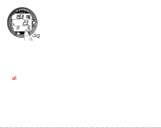
Figure 6.2. Diving display. Present depth is 19.3 m /63 ft and nodecompression stop
time limit is 23 minutes in A0/P1 mode. Maximum depth during this dive was 19.8
m/65 ft, elapsed dive time is 16 minutes.The current time 10:20 [10:20 am] is shown
for 5 seconds after pressing the TIME button.
Alternative displays, by pressing the TIME button, show:
the current time, shown as TIME
•
NOTE
6.1.2. Bookmark
It is possible to make special marks in the profile memory during a dive. These
Bookmarks will be shown as a dive log symbol when scrolling the profi le memory on
the computer display. The Bookmarks will also be shown as annotations in the PCsoftware, Suunto Dive Manager. To make a bookmark on the profile memory during
a dive press the PLAN button.
56
In Dive Mode the TIME display automatically changes back
to DIVE TIME.
Page 57

Figure 6.3. Diving display. An annotation, Bookmark, is done in the profile memory
during a dive by pressing the PLAN button. Note the Logbook symbol.
6.1.3. Consumed Bottom Time (CBT)
The available no-decompression time is also shown visually in the multi-function bar
graph on the left side of the display. When your available no-decompression time decreases below 200 minutes, the first (lowest) bar graph segment appears. As your
body absorbs more nitrogen, more segments start to appear.
Green Zone– As a safety precaution Suunto recommends you should maintain the
no-decompression bar graph within the green zone. Segments start to appear when
the available no-decompression time decreases below 100, 80, 60, 50, 40, 30, and
20 minutes.
Yellow Zone– As the bars reach the yellow zone, your no-decompression stop time
is less than 10 or 5 minutes and you are getting very close to no-decompression limits.
At this point, you should start your ascent towards the surface.
57
Page 58

Red Zone– As all of the bars appear (red zone), your no-decompression stop time
has become zero and your dive has become a decompression stop dive (for more
information see Section 6.1.5. Decompression dives).
6.1.4. Ascent rate indicator
The ascent rate is displayed graphically along the right hand side with a vertical bar.
When the maximum allowed ascent rate is exceeded, the fifth SLOW warning segment
and the STOP sign appear and the depth reading starts to blink, indicating that the
maximum ascent rate has been exceeded continuously or that the current ascent rate
is significantly above the allowed rate.
Table 6.1. Ascent rate indicator
The equivalent ascent speedAscent rate incicator
Below 4 m/min / 13 ft/minNo segment
4–6 m/min / 13–20 ft/minOne segment
6–8 m/min / 20–26 ft/minTwo segments
8–10 m/min / 26–33 ft/minThree segments
10–12 m/min / 33–39 ft/minFour segments
Four segments, the SLOW segment, blinking depth reading, the
STOP sign and an audible alarm
58
Above 12 m/min /39 ft/min or continuously 10
m/min / 33 ft/min
Page 59

When the maximum allowed ascent rate is exceeded the fifth SLOW warning segment
and the STOP sign appear and the depth reading starts to blink indicating that the
maximum ascent rate has been exceeded continuously or that the ascent rate is above
the allowed maximum rate.
Whenever the SLOW warning segment and the STOP sign appear, you should immediately slow down your ascent. When you reach the depth zone between 6 m to 3 m
/20 ft to 10 ft, the STOP and CEILING depth labels will advise you to make a Mandatory
Safety Stop. Wait until the warning disappears. You should not ascend shallower than
3 m/10 ft with the Mandatory Safety Stop warning on.
Figure 6.4. Ascent Rate Indicator. Blinking depth reading, SLOW and four segments
shown: ascent rate is more than 10 m/min/33 ft/min. This is a caution to slow down!
The STOP sign means that you are advised to make a Mandatory Safety Stop when
you reach the depth of 6 m/20 ft.
59
Page 60

WARNING
6.1.5. Decompression dives
When your NO DEC TIME becomes zero, your dive changes into a decompression
dive. Therefore, you must perform one or more decompression stops on your way to
the surface. The NO DEC TIME on your display will be replaced by an ASC TIME,
and a CEILING notation will appear. An upward pointing arrow will also prompt you
to start your ascent.
Figure 6.5. Decompression dive.
60
DO NOT EXCEED THE MAXIMUM ASCENT RATE! Rapid ascents increase the risk of injury. You should always make the
Mandatory and Recommended Safety Stops after you have exceeded the maximum recommended ascent rate. If this Mandatory
Safety Stop is not completed, the decompression model will
penalize your next dive(s).
Page 61

If you exceed the no-decompression limits on a dive, the dive computer will provide
the decompression information required for ascent. After this, the instrument will
continue to provide subsequent interval and repetitive dive information.
Rather than requiring you to make stops at fixed depths, the dive computer lets you
decompress within a range of depths (continuous decompression).
The ascent time (ASC TIME) is the minimum amount of time needed to reach the
surface in a decompression dive. It includes:
the three (3) minute Recommended Safety Stop
•
the time needed to ascend to the ceiling at an ascent rate of 10 m/33 ft per minute.
•
The ceiling is the shallowest depth to which you should ascend.
the time needed at the ceiling
•
the time needed at the Mandatory Safety Stop (if any)
•
the time needed to reach the surface after the ceiling and Safety Stops have been
•
completed
WARNING
YOUR ACTUAL ASCENT TIME MAY BE LONGER THAN DISPLAYED BY THE INSTRUMENT! The ascent time will increase
if you:
•
remain at depth
•
ascend slower than 10 m/33 ft per minute or
•
make your decompression stop deeper than at the ceiling
These factors will also increase the amount of air required to
reach the surface.
61
Page 62

Ceiling, ceiling zone, floor and decompression range
When in decompression, it is important that you understand the meaning of ceiling,
floor, and decompression range.
The ceiling is the shallowest depth to which you should ascend when in decom-
•
pression. At this depth, or below, you must perform all stops.
The ceiling zone is the optimum decompression stop zone. It is the zone between
•
the minimum ceiling and 1.4m/6 ft below the minimum ceiling.
The floor is the deepest depth at which the decompression stop time will not in-
•
crease. Decompression will start when you pass this depth during your ascent.
The decompression range is the depth range between the ceiling and floor. Within
•
this range, decompression takes place. However, it is important to remember that
the decompression will be very slow at, or close to, the floor.
Figure 6.6. Ceiling and Floor zone. Recommended and Mandatory Safety Stop zone
between 6 m and 3 m/20 ft and 10 ft.
62
Page 63

The depth of the ceiling and floor depends on your dive profile. The ceiling depth will
be fairly shallow when you enter the decompression mode, but if you remain at depth,
it will move downward and the ascent time will increase. Likewise, the floor and ceiling
may change upwards while you are decompressing.
When conditions are rough, it may be difficult to maintain a constant depth near the
surface. In such cases, it is more manageable to maintain an additional distance below
the ceiling, to ensure that the waves do not lift you above the ceiling. Suunto recommends that decompression takes place deeper than 4 m/13 ft, even if the indicated
ceiling is shallower.
NOTE
It will take more time and more air to decompress below the ceiling
than at the ceiling.
WARNING
Display below the floor
The blinking ASC TIME sign and an upward pointing arrow indicate that you are below
the floor. You should start your ascent immediately. The ceiling depth is shown on the
right top corner and the minimum total ascent time on the right side of the center window.
NEVER ASCEND ABOVE THE CEILING! You must not ascend
above the ceiling during your decompression. In order to avoid
doing so by accident, you should stay somewhat below the ceiling.
63
Page 64

Figure 6.7. Decompression dive, below floor. Upward pointing arrow, blinking ASC
TIME label and an audible alarm tell you to ascend. Minimum total ascent time including
safety stop is 7 minutes. Ceiling is at 3 m/10 ft.
Display above the floor
When you ascend above the floor, the ASC TIME sign stops blinking and the upward
pointing arrow disappears. Below is an example of a decompression dive above the
floor.
64
Page 65

Figure 6.8. Decompression dive, above the floor. The upward pointing arrow has
disappeared and the ASC TIME label has stopped blinking, which means that you are
in the decompression range.
Decompression will now begin, but is very slow. Therefore, you should continue your
ascent.
Display at the ceiling zone
When you reach the ceiling zone, the display will show you two arrows pointing at
each other (the “hour glass” icon). Below is an example of a decompression dive at
the ceiling zone.
65
Page 66

Figure 6.9. Decompression dive, at ceiling zone. Two arrows point at each other (“hour
glass”). You are in the optimum ceiling zone at 3.5 m/11 ft and your minimum ascent
time is 5 minutes. Pressing TIME button activates alternative display.
During the decompression stop, ASC TIME will count down towards zero. When the
ceiling moves upwards, you can ascend to the new ceiling. You may surface only after
the ASC TIME and CEILING labels have disappeared, which means that the decompression stop and any Mandatory Safety Stop have been completed. You are advised,
however, to stay until the STOP sign has also disappeared. This indicates that the
three (3) minute Recommended Safety Stop has also been completed.
Display above the ceiling
If you ascend above the ceiling during a decompression stop, a downward pointing
arrow will appear and a continuous beeping starts.
66
Page 67

Figure 6.10. Decompression dive, above ceiling. Note a downward pointing arrow, an
Er warning and an audible alarm. You should immediately (within 3 minutes) descend
to or below ceiling.
In addition, an Error warning (Er) reminds you that you have only three (3) minutes to
correct the situation. You must immediately descend to, or below, the ceiling.
If you continue to violate the decompression, the dive computer will go into a permanent
Error Mode. In this mode, the instrument can only be used as a depth gauge and timer.
You must not dive again for at least 48 hours (refer to Section 5.5. Error conditions).
6.2. Diving in NITROX mode
This dive computer can be set for diving with standard air only (Air mode) or it can be
set for diving with Enriched Air Nitrox (EANx) (Nitrox mode).
67
Page 68

6.2.1. Before diving in the NITROX mode
If set to the NITROX mode, the correct oxygen percentage of the gas in your cylinder
must always be entered into the computer to ensure correct nitrogen and oxygen
calculations. The dive computer adjusts its mathematical nitrogen and oxygen calculation models accordingly. The dive computer will not accept fractional percentage
values of oxygen concentration. Do not round up fractional percentages. For example,
31.8% oxygen should be entered as 31%. If you want to adjust the computer to provide
more conservative calculations, use the personal adjustment feature to affect decompression calculations, or reduce the PO2setting to affect oxygen exposure according
to the entered O2% and PO2values. Calculations based on nitrox use result in longer
no-decompression times and shallower maximum depths than diving with air.
When the dive computer is set in NITROX mode, the Dive Planning mode calculates
using the O2% and PO2values that are currently in the computer.
Default nitrox settings
In the NITROX mode, the default setting is standard air (21% O2). It remains in this
setting until the O2% is adjusted to any other percentage of oxygen (22%–50%). The
default setting for maximum oxygen partial pressure is 1.4 bar, however you are able
to set it in the range of 1.2–1.6 bar.
If unused, the computer will retain the manually entered value for the selected oxygen
percentage for about two hours, after which it will revert to the default setting of 21%
O2.
68
Page 69

6.2.2. Oxygen displays
When the NITROX mode is activated, the display will show the information in the figure
below. In the NITROX mode, the maximum operational depth is calculated based on
set O2% and PO2values.
If set to the NITROX mode, the Suunto will additionally show on the alternative display:
the oxygen percentage, labeled O2%
•
the set oxygen partial pressure limit, labeled PO
•
the current oxygen toxicity exposure, labeled OLF%
•
maximum depthallowed based on the set oxygen percentage and partial pressure
•
2
limit
Figure 6.11. Nitrox display. Maximum depth based on set O2% (21%) and PO2 (1.4
bar) is 54.1 m/177 ft.
69
Page 70

In the Dive modes, the oxygen percentage labeled with O2% and the current oxygen
toxicity exposure shown with an Oxygen Limit Fraction (OLF) bar graph are shown
(Fig. 3.22. and Fig. 3.23.). The O2% is shown until the remaining air time is less than
30 minutes. After this, the remaining air time is displayed in its place. During a dive,
the oxygen partial pressure, labeled with PO2, is also shown instead of the maximum
depth in the upper right display, if the partial pressure is greater than 1.4 bar or the
set value.
Figure 6.12. Oxygen partial pressure and OLF displays. There is an audible alarm as
oxygen partial pressure is greater than 1.4 bar or set value, and/or the OLF has reached
80% limit.
By pressing the TIME button during a nitrox dive, the alternative display appears,
which includes:
• current time
• temperature
• Consumed Bottom Time
70
Page 71

• maximum depth (during decompression stop dive)
Figure 6.13. Alternative display. Pressing the TIME button displays the current time,
maximum depth and CBT.
After five seconds, the display will automatically revert to the original display.
6.2.3. Oxygen limit fraction (OLF%)
If set to the NITROX mode, in addition to tracking the diver's exposure to nitrogen, the
instrument tracks the exposure to oxygen. These calculations are treated as entirely
separate functions.
The dive computer calculates separately for Central Nervous System oxygen toxicity
(CNS) and Pulmonary Oxygen toxicity, the latter measured by the addition of Oxygen
Toxicity Units (OTU). Both fractions are scaled so that the maximum tolerated exposure
for each is expressed as 100%.
71
Page 72

The Oxygen Limit Fraction (OLF) has 11 segments, each representing 10%.The
Oxygen Limit Fraction (OLF%) displays only the value of the higher of the two calculations. The oxygen toxicity calculations are based on the factors listed in Section 10.3.
Oxygen exposure .
When the OTU value meets and exceeds the CNS value then in addition to displaying
its percentage the lowest segment blinks to indicate that the value shown relates to
OTU.
Figure 6.14. The lowest bar graph blinks to indicate that the OLF value shown relates
to OTU.
72
Page 73

6.3. Diving in the GAUGE mode
If set to Gauge mode, the dive computer can be used for diving with technical diving
mixed gases. If you are trained for technical diving and you plan to use Gauge mode
on a regular basis, it may be preferable to set the instrument permanently to its Gauge
mode. If set to Gauge mode, the text GAUGE is shown after activation. In the Gauge
mode the present depth, maximum depth, dive time, remaining air time and ascent
rate indicator are displayed during the dive. In addition, temperature and current time
are shown in the alternative display.
Figure 6.15. The Gauge mode. The present depth, maximum depth, dive time,
remaining air time and ascent rate indicator are displayed during the dive.
This mode can also be used for other purposes like snorkeling, free diving, depth
measurements, and so on.
NOTE
The mode does not provide decompression information.
73
Page 74

74
NOTE
If you dive with the GAUGE mode, it is not possible to change
between the modes before the no fly time has counted down.
Page 75

7. AFTER DIVING
Once back at the surface, Suunto Vyper continues to provide post-dive safety information and alarms. Calculations to enable repetitive dive planning also help to maximize
diver safety.
Table 7.1. Alarms
IndicationSymbol on display
Diver Attention Symbol - Extend Surface Interval
Violated Decompression Ceiling or Too Long Bottom
Time
Do Not Fly Symbol
7.1. Surface interval
An ascent to any depth shallower than 1.2 m/4 ft will cause the DIVE display to be
replaced by the SURFACE display:
75
Page 76

Figure 7.1. Surface display. You have surfaced from a 18 minute dive, which maximum
depth was 20.0 m/66 ft. The present depth is 0.0 m/0 ft. The Airplane symbol indicates
that you should not fly and diver attention symbol indicates that you should prolong
your surface interval time.
• maximum depth of last dive in meters/feet
• dive time of last dive in minutes, shown as DIVE TIME
• present depth in meters/feet
• no-flying warning indicated by an airplane icon
• Altitude Adjustment setting
• Personal Adjustment setting
• Diver attention symbol indicates if you should prolong your surface interval time
• STOP label for 5 min, if the Mandatory Safety Stop was violated
• Er, if the decompression ceiling was violated (= Error Mode)
• the current temperature in °C/°F
76
Page 77

Figure 7.2. Surface interval, the surface time and no-flying time displays: Pressing the
TIME button once the surface time display is shown and by pressing the TIME button
twice the no-flying time display is shown, indicated by the airplane symbol.
Or when the TIME button is pressed once or twice:
• the current time, shown as TIME
• the surface time in hours and minutes (separated by a colon), telling the duration
of the present surface interval
• the desaturation/no-flying time in hours and minutes is shown next to the airplane
in the center window of the display
If set to NITROX mode, the following information will also be shown:
the oxygen percentage labeled O2%
•
the current oxygen toxicity exposure labeled OLF%
•
77
Page 78

7.2. Dive numbering
Several repetitive dives are considered to belong to the same repetitive dive series
when the dive computer has not counted the no-fly time to zero. Within each series,
the dives are given individual numbers. The first dive of the series will be numbered
as DIVE 1, the second as DIVE 2, the third as DIVE 3, and so on.
If you start a new dive with less than five (5) minutes of surface interval time, the dive
computer interprets this as a continuation of the previous dive and the dives are considered to be the same. The diving display will return, the dive number will remain
unchanged, and the dive time will begin where it left off. After five (5) minutes on the
surface, subsequent dives are, by definition, repetitive. The dive counter displayed in
the Planning mode will increment to the next number if another dive is made.
7.3. Flying after diving
In the DIVE mode, the no-fly time is displayed in the center window next to the airplane
image. In the TIME mode, the airplane image is shown in the top left corner. Flying
or traveling to a higher altitude should be avoided at any time when the computer is
counting down the no-fly time.
NOTE
The no-fly time is always at least 12 hours, or equivalent to the so-called desaturation
time (if longer than 12 hours).
In the Permanent Error mode and GAUGE mode, the no-fly time is 48 hours.
The Divers Alert Network (DAN) recommends the following on no-fly times:
78
The airplane symbol is not shown on the stand-by display. You
should always activate the dive computer and check that the airplane symbol is not displayed prior to flying.
Page 79

A minimum surface interval of 12 hours would be required in order to be reasonably
•
assured a diver will remain symptom free upon ascent to altitude in a commercial
jetliner (altitude up to 2,400 m/8,000 ft).
Divers who plan to make daily, multiple dives for several days, or make dives that
•
require decompression stops, should take special precautions and wait for an extended interval beyond 12 hours before a flight. Further, the Undersea and Hyperbaric Medical Society (UHMS) suggests divers using standard air cylinders and
exhibiting no symptoms of decompression illness wait 24 hours after their last dive
to fly in an aircraft with cabin pressure up to 2,400 m/8,000 ft. The only two exceptions to this recommendation are:
If a diver has less than two (2) hours total accumulated dive time in the last 48
•
hours, a 12 hour surface interval before flying is recommended.
Following any dive that required a decompression stop, flying should be delayed
•
for at least 24 hours, and if possible, for 48 hours.
Suunto recommends that flying is avoided until all the DAN and UHMS guidelines,
•
as well as the dive computer’s no-fly conditions, are satisfied.
7.4. Memories and Data Transfer [1 MEMORY]
The memory options for this dive computer include the combined Logbook and Dive
Profile Memory, Dive History Memory and the Data Transfer and PC-Interface functions.
The dive entry time and date is registered in the Logbook memory. Always check before
diving that the time and date are correctly set, especially after travelling between different time zones.
79
Page 80

Figure 7.3. Memory options [3 MEMORY].
7.4.1. Logbook and Dive Profile Memory [1 LOGBOOK])
The Suunto Vyper has a very sophisticated, high capacity Logbook and Profile Memory.
The data is recorded in the profile memory based on the selected sample rate.
Dives shorter than the recording interval are not registered.
To enter the Logbook Memory Mode, select MODE- 1 MEMORY- 1 LOGBOOK.
For each dive there are four pages of logbook dive information. Use the scroll buttons
to scroll the display between Logbook pages I, II, III and IV. The data of the most recent
dive is shown first.
The END text is displayed between the oldest and most recent dive. The following
information will be shown on three pages:
80
Page 81

Figure 7.4. Logbook, end of the memory. END text is displayed between oldest and
the most recent dive.
Page I, main display
date of dive
•
dive start time
•
dive number
•
81
Page 82

Figure 7.5. Logbook, page I. Scroll different pages of specific dive.
Page II
maximum depth
•
NOTE
total dive time
•
dive number in the dive series
•
temperature at the maximum depth
•
Altitude Adjustment setting (not displayed in Gauge mode)
•
Personal Adjustment setting (not displayed in Gauge mode)
•
SLOW label, if the diver has violated the maximum ascent rate
•
STOP label, if the Mandatory Safety Stop was violated
•
ASC TIME label, if the dive was a decompression stop dive
•
Diver attention symbol, if the dive was started while symbol was displayed
•
82
Due to lower resolution, the reading may differ from the maximum depth reading of the Dive History up to 0.3 m /1 ft
Page 83

downward pointing arrow, if the ceiling was violated
•
oxygen percentage (only in Nitrox mode)
•
maximum OLF during the dive (only in Nitrox mode)
•
Figure 7.6. Logbook, page II. Main dive related data.
Page III
dive number in the dive series
•
average depth
•
surface interval time before the dive
•
83
Page 84

Figure 7.7. Logbook, page III. Surface interval time and average depth.
Page IV
• dive number in the dive series
• the profile of the dive profile, automatic scrolling during which:
logbook symbol blinks when the user has pressed the PLAN button for Bookmark
• blinking SLOW label when registered
• blinking ASC TIME label when the dive became a decompression dive
84
Page 85

Figure 7.8. Logbook, page IV. Profile of a specific dive.
Press the SMART (Select) button once to change the scroll buttons to scroll the different
dives forward and backward. Press the SMART (>Select) button again to change
function of the scroll buttons back to scroll the different pages of the selected dive.
When searching the dives, only the page 1 is shown. The END text is displayed
between the oldest and the most recent dive.
NOTE
The memory will retain approximately the last 36 hours of dive
time. After that, when new dives are added, the oldest dives are
deleted. The contents of the memory will remain when the battery
is changed (providing that the battery has been replaced according
to the instructions).
NOTE
Several repetitive dives are considered to belong to the same
repetitive dive series if the no-fly time has not ended. See Section 7.2. Dive numbering for further information.
85
Page 86

Dive Profile memory [PROF]
The scrolling of the profile will start automatically when the Logbook page IV (PROF)
is entered. With the default setting, the dive profile is recorded and displayed in 20second increments with each display being shown for about three seconds. The depths
shown are the maximum values of each interval. Pressing any button stops the scrolling
of the profile.
7.4.2. Dive history Memory [2 HISTORY]
The dive history is a summary of all the dives recorded by the dive computer. To enter
the Dive History Memory mode, select MODE- 1 MEMORY- 2 HISTORY.
Figure 7.9. Dive History Memory Mode. [2 HISTORY]
86
Page 87

The following information will be shown on the display:
Figure 7.10. Dive History information. Total number of dives, dive hours and maximum
depth.
The Dive History Memory can hold a maximum of 999 dives and 999 diving hours.
When these maximum values are reached, the counters will start again from zero.
NOTE
The maximum depth can be reset to 0.0 m/0 ft using the PC Interface unit and the downloadable Suunto Dive Manager software.
87
Page 88

7.4.3. Data Transfer and PC-Interface [3 TR-PC]
The Suunto DM4 with Movescount (DM4) is an optional software that greatly enhances
the functionality of your Suunto Vyper. With the DM4 software, you can download dive
data from your dive computer to your laptop. After that, you can view and organize all
the data recorded with your Suunto . You can plan dives (with Suunto Dive Planner),
print copies of your dive profiles, and also upload your dive logs to share with your
friends at http://www.movescount.com (see Section 7.5. Movescount). You can always
download the latest version of the DM4 from http://www.suunto.com. Please check
for updates regularly as new features are constantly being developed. The following
data is transferred from your dive computer to your laptop (optional, cable required):
• depth profile of the dive
• dive time
• preceding surface interval time
• dive number
• dive start time (year, month, day, and time)
• dive computer settings
• oxygen percentage settings and maximum OLF (in the mode)
• tissue calculation data
• additional dive information (for example, SLOW and Mandatory Safety Stop violations, Diver Attention Symbol, Bookmark, Surfaced Mark, Decompression Stop
Mark, and Ceiling Error Mark)
• dive computer serial number
• personal information (30 characters)
By using the DM4, you are able to enter setup options such as:
input a personal, 30-character field into the Suunto instrument.
•
88
Page 89

reset the Scuba History's maximum depth to zero
•
manually add comments, multimedia and other personal information to the PC-
•
based dive data files
change the sample rate for profile records/logbook from the default 20 second in-
•
terval to 10, 30 or 60 seconds
To enter the Data Transfer mode, select MODE- 1 MEMORY- 3 TR - PC.
NOTE
After you have finished the data transfer, press the SMART (Quit) to exit Data Transfer
mode. If a button is not pressed or no data is transferred within 5 minutes, the instrument beeps and returns to the timekeeping display automatically
7.5. Movescount
Movescount is an online sports community that offers you a rich set of tools to manage
all you sports and create engaging stories about your diving experiences. Movescount
offers you new ways to get inspired and share your best dives with other community
members!
To connect to Movescount:
Go to www.movescount.com.
1.
Register and create your free Movescount account.
2.
Download and install the Suunto DM4 with Movescount software from the
3.
Movescount.com website if you do not already have the DM4 installed on your
laptop
While in the Data Transfer mode, the connector/water contacts
are used only for the data transfer. The Dive Mode IS NOT automatically activated if the contacts are submerged.
89
Page 90

To transfer data:
Connect your dive computer to your laptop.
1.
Download your dives to the DM4 on your laptop.
2.
Follow the instructions on the DM4 on how to transfer your dives to your
3.
Movescount.com account.
7.6. Simulation Mode [SIMUL]
The Simulation mode can be used to acquaint yourself with the features and displays
of the instrument before diving, to plan dives in advance, for demonstration or education
purposes, or just for pleasure.
The dive computer has two simulation modes:
The DIVE SIMULATOR
•
The DIVE PLANNING SIMULATOR
•
Figure 7.11. Dive Simulation options [2 SIMUL]
90
Page 91

In Simulation Mode, time moves four times faster than real time (when diving), for
example, 15 s = 1 min.
7.6.1. Dive Simulator [1 SIMDIVE]
The Dive Simulator mode is an excellent tool for becoming familiar with the dive
computer and planning your dives. Suunto recommends using the dive simulator to
run through different dive scenarios. The Dive Simulator will allow you to “perform”
dive profiles of your choice and see what the display would look like during an actual
dive. This includes basic dive information, as well as audible and visual warnings. To
enter the Dive Simulator mode, select MODE- 2 SIMUL- 1 SIMDIVE.
Figure 7.12. Dive Simulator mode [1 SIMDIVE]. Descend by pressing the arrow down
(TIME) button and ascend by pressing the arrow up (PLAN) button.
91
Page 92

7.6.2. Dive Planning Simulator [2 SIMPLAN]
The Dive Planning Simulator mode shows you the present no-decompression limits.
In this mode, you are also able to add the desired surface interval increment to present
surface interval time, which allows you to plan your dives in advance.
This mode is also used to add the desired surface intervals for dive simulations. Add
the desired surface interval increment to present surface interval by pressing the arrow
down (TIME) and arrow up (PLAN) buttons.
To enter the Dive Planning Simulator mode select MODE- 2 SIMUL- 2 SIMPLAN.
Figure 7.13. Dive Planning Simulator mode [2 SIMPLAN]. Add desired surface interval
increment (to present shown surface interval) by pressing TIME and PLAN buttons.
This display is only shown for repetitive dives.
92
NOTE
This display is only shown for repetitive dives.
Page 93

NOTE
The Dive Planning Simulator mode is disabled in Gauge mode
and in Error mode.
93
Page 94

8. CARE AND MAINTENANCE OF MY SUUNTO DIVING COM-
PUTER
The SUUNTO dive computer is a sophisticated precision instrument. Although it is
designed to withstand the rigors of scuba diving, you must treat it with the same
proper care and caution as any other precision instrument.
WARNING
WATER CONTACTS AND PUSH BUTTONS
•
Contamination or dirt on the water contacts/connector or push buttons may prevent
the automatic activation of the Dive Mode and cause problems during the data
transfer. Therefore, it is important that the water contacts and push buttons are
kept clean. If the water contacts are active (AC text remains on display) or the Dive
Mode activates on its own, the reason for this is probably contamination or invisible
marine growth, which may create an electric current between the contacts. It is
important that the dive computer is carefully washed in fresh water after the day’s
diving is completed. The contacts can be cleaned with fresh water and, if necessary,
a mild detergent and a soft brush. Sometimes it might be necessary to remove the
instrument from the protective boot for cleaning.
CARE OF YOUR DIVE COMPUTER
•
NEVER try to open the case of the dive computer.•
94
The built-in depth sensor is a sophisticated precision component.
Keep the area around the depth sensor clear from dirt, sand, dust
or other substances. Rinse the device thoroughly with fresh water
and dry it with a soft towel. Never use pins, needles or other objects to clean the depth sensor.
Page 95

• Have your dive computer serviced every two years or after 200 dives (whichever
comes first) by an authorized dealer or distributor. This service will include a
general operational check, replacement of the battery, and water resistance
check. The service requires special tools and training. Therefore, it is advisable
to contact an authorized SUUNTO dealer or distributor for service. Do not attempt to do any servicing that you are not sure of.
• Should moisture appear inside the case, immediately have the instrument
checked by your SUUNTO dealer or distributor.
• Should you detect scratches, cracks or other such flaws on the display that
may impair its durability, immediately have it replaced by your SUUNTO dealer
or distributor.
• Wash and rinse the unit in fresh water after every use.
• Protect the unit from shock, extreme heat, direct sunlight, and chemical attack.
The dive computer cannot withstand the impact of heavy objects like scuba
cylinders, nor chemicals like gasoline, cleaning solvents, aerosol sprays, adhesive agents, paint, acetone, alcohol, and so on. Chemical reactions with such
agents will damage the seals, case and finish.
• Store your dive computer in a dry place when you are not using it.
• The dive computer will display a battery symbol as a warning when the power
gets too low. When this happens, the instrument should not be used until the
battery has been replaced.
• Do not fasten the strap of your dive computer too tightly. You should be able
to insert your finger between the strap and your wrist. Shorten the strap by
cutting it if you do not expect to need the extra length.
95
Page 96

MAINTENANCE
•
The instrument should be soaked, thoroughly rinsed with fresh water, then dried
with a soft towel after each dive. Make sure that all salt crystals and sand particles
have been flushed out. Check the display for possible moisture or water. DO NOT
use the dive computer if you detect any moisture or water inside. Contact an authorized Suunto dealer for battery replacement or other service.
CAUTION!
• Do not use compressed air to blow water off the unit.
• Do not use solvents or other cleaning fluids that might cause damage.
• Do not test or use the dive computer in pressurized air.
WATER RESISTANCE INSPECTION
•
The water resistance of the unit must be checked after replacing the battery or
after other service operations. The check requires special equipment and training.
You must frequently check the display for any sign of leaks. If you find moisture
inside your dive computer, there is a leak. A leak must be corrected without delay
as moisture will seriously damage the unit, even beyond repair. SUUNTO does
not take any responsibility for damage caused by moisture in the dive computer
unless the instructions of this manual are carefully followed. In the event of a leak,
immediately take the dive computer to an authorized SUUNTO dealer or distributor.
FAQs
For more information on service, please refer to FAQs on www.suunto.com.
96
Page 97

9. BATTERY REPLACEMENT
NOTE
CAUTION
When working with the battery compartment, cleanliness is extremely important. Even
the smallest dirt particles may cause a leakage when you dive.
9.1. Battery kit
The battery kit includes a 3.0 V coin type lithium cell battery and a lubricated O ring.
When handling the battery do not make contact with both of the poles at the same
time. Do not touch the surfaces of the battery with your bare fingers.
9.2. Required tools
A flat 1.5 mm screwdriver or a special tool for spring bars (K5857).
•
Soft cloth for cleaning.
•
Needlenose pliers or small screwdriver for turning securing ring.
•
It is advisable to contact an authorized Suunto representative for
battery replacement. It is imperative that the change is made in
a proper manner to avoid any leakage of water into the battery
compartment or computer.
When the battery is changed, all nitrogen and oxygen uptake data
is lost. Therefore, the no-fly time shown by the computer should
have reached zero or you must wait for 48 hours, or preferably
up to 100 hours, before you dive again.
97
Page 98

9.3. Replacing the battery
The battery and the buzzer are located in the back of the instrument in a separate
compartment. To change the battery:
Remove the computer from the console or boot.
1.
Wrist model:
Pull off the boot. Remove it first from the front end with the longer part of the
•
strap.
Disassemble the shorter part of the strap with a flat 1.5 mm screwdriver or a
•
special tool for spring bars. The longer part of the strap may stay on but removing it may ease the work later on.
Console model:
Remove the dive computer from the console according the instructions of the
•
console.
Thoroughly rinse and dry the computer.
2.
Open the securing ring of the battery compartment lid by pushing it down and
3.
rotating it clockwise. You may use a pointed nose pliers or a small screwdriver
as an aid in the rotating. Put the pliers ends into the holes of the securing ring or
the screwdriver onto the side of the right tooth on the ring and turn the ring
clockwise. Be careful not to damage any of the parts.
Remove the ring.
4.
Carefully remove the lid with the beeper attached to it. You can remove the lid by
5.
pressing with your finger on the outermost edge of the lid while simultaneously
pulling with your nail at the opposite side. Don't use sharp metal objects as they
might damage the O-ring or the sealing surfaces.
Remove the O-ring and the battery retainer.
6.
98
Page 99

Carefully remove the battery. Do not damage the electrical contacts or the sealing
7.
surface.
Check for any traces of flooding, particularly between the beeper and the lid, or
8.
for any other damage. In case of a leak or any other damage, bring the dive
computer to an authorized SUUNTO dealer or distributor for check and repair.
Check the condition of the O-ring; a defective O-ring may indicate sealing or
9.
other problems. Dispose the old O-ring, even if it seems to be in good condition.
Check that the battery compartment, battery holder and lid are clean. Clean with
10.
soft cloth if necessary.
Gently insert the new battery in the battery compartment. Check the polarity of
11.
the battery: the “-” mark should point toward the bottom of the compartment and
the “+” mark upwards.
Reinstall the battery retainer in its correct position.
12.
Check that the new lubricated O-ring is in good condition. Put it in the right position
13.
on the battery compartment lid. Be very careful not to get any dirt on the o-ring
or its sealing surfaces.
Carefully press the lid onto the battery compartment with your thumb, while
14.
making sure that the O-ring is not at any point protruding out on the edge.
Put your other thumb through the locking ring. Press this thumb firmly against the
15.
lid and release the other one. Make sure that the lid is pressed completely down!
Turn the locking ring counterclockwise with your free thumb and fingers until it
16.
snaps into its locked position.
The dive computer should now active its timekeeping mode and show time 18:00
17.
[6:00 PM] and date SA 01,01. Activate the instrument. Check that
all display segments work.
•
99
Page 100

the low battery warning is off.
•
the buzzer beeps and backlight works.
•
all the settings are correct. Reset if necessary.
•
Install the dive computer back into the console or boot and reassemble the strap.
18.
The instrument is now ready for use.
Wrist model:
Assembling into the boot: First insert the longer strap in its hole in the front of
•
the boot and then the dive computer into its cavity in the boot starting at the
back end. Then snap also the long strap end of the instrument into the boot.
Stretch the boot as needed.
Assemble the shorter part of the strap. Use the spring bar tool or small
•
screwdriver to compress the spring bars. Make sure that the spring bars get
fully seated so they will not come off their holes.
Console model
Refit the dive computer in the console according the instructions of the console.
•
CAUTION
100
Check after the first dives for possible moisture under the transparent battery compartment lid, indicating a leak.
 Loading...