

Page 1

USER’S GUIDE
CUSTOMER SERVICE CONTACTS
Suunto Oy Phone +358 9 875870
Fax +358 9 87587301
Suunto USA Phone 1 (800) 543-9124
Canada Phone 1 (800) 776-7770
European Call Center Phone +358 2 284 11 60
Suunto Website
www.suunto.com
1
EN
Page 2

TABLE OF CONTENTS
CHAPTER 1 INTRODUCTION .......................................................... 6
1.1 GENERAL INFORMATION .......................................................................................... 6
1.2 MAIN FUNCTIONS (MODES) ...................................................................................... 6
1.2.1 Backlight Features ......................................................................................... 7
1.2.2 Water Resistance .......................................................................................... 7
1.3 BUTTON FUNCTIONS ................................................................................................ 7
1.3.1 The [Mode] Button ......................................................................................... 7
1.3.2 The [+] Button ................................................................................................ 8
1.3.3 The [-] Button ................................................................................................. 8
1.3.4 The [Select] Button ........................................................................................ 8
1.4 LCD DISPLAY .............................................................................................................. 8
1.5 MEASUREMENTS AND UNITS ................................................................................. 10
1.5.1 Selecting the Units of Measurement ............................................................ 10
1.6 PRESSURE SENSOR CALIBRATION ........................................................................ 11
1.7 CARE AND MAINTENANCE ....................................................................................... 11
1.7.1 Battery Replacement ................................................................................... 12
CHAPTER 2 TIME MODE ............................................................... 13
2.1 HOW TO SET THE TIME .......................................................................................... 13
2.2 DAILY ALARM SUB MODE ........................................................................................ 15
2.2.1 How to Set the Daily Alarms ........................................................................ 15
2.3 STOPWATCH SUB MODE ........................................................................................ 16
2.3.1 How to Use the Stopwatch .......................................................................... 16
2.4 COUNTDOWN TIMER SUB MODE........................................................................... 17
2.4.1 How to Set the Countdown Timer ................................................................ 18
2
Page 3

2.4.2 How to Start the Countdown Timer .............................................................. 18
2.5 DUAL TIME SUB MODE (ALTIMAX , S-LANDER) ..................................................... 19
2.5.1 Setting the Dual Time Function ................................................................... 19
CHAPTER 3 ALTIMETER MODE .................................................... 20
3.1 SETTING THE ALTIMETER ....................................................................................... 21
3.2 ALTITUDE DIFFERENCE MEASUREMENT SUB MODE .......................................... 23
3.2.1 How to Start the Altitude Difference Measurement ...................................... 23
3.3 24-HOUR MEMORY SUB MODE ............................................................................... 24
3.4 LOGBOOK SUB MODE ............................................................................................. 24
3.4.1 How to Start and Stop a Logbook ................................................................ 26
3.4.2 Fast Cumulative Button ............................................................................... 26
3.5 LOGBOOK HISTORY SUB MODE ............................................................................ 27
3.5.1 Clearing the Logbook History ...................................................................... 28
CHAPTER 4 BAROMETER MODE .................................................. 28
4.1 PRESSURE DIFFERENCE MEASUREMENT SUB MODE ........................................ 29
4.1.1 How to Start the Pressure Difference Measurement.................................... 30
4.2 4-DAY MEMORY SUB MODE .................................................................................... 30
4.3 SEA LEVEL PRESSURE SUB MODE ........................................................................ 31
4.3.1 Setting the Sea Level Pressure ................................................................... 31
4.4 BAROMETRIC TREND INDICATOR .......................................................................... 32
CHAPTER 5 COMPASS MODE (VECTOR AND X-LANDER) ............ 32
5.1 BEARING TRACKING SUB MODE ............................................................................ 34
5.2 DECLINATION ADJUSTMENT SUB MODE ............................................................... 34
5.2.1 Setting the Local Declination ....................................................................... 35
5.3 CALIBRATING THE COMPASS ................................................................................. 35
3
Page 4

CHAPTER 6 FREQUENTLY ASKED QUESTIONS........................... 36
6.1 GENERAL .................................................................................................................. 36
6.1.1 Is the Wristop Computer waterproof? .......................................................... 36
6.1.2 How long will the battery last? ..................................................................... 36
6.1.3 What do the segments on the circumference mean? .................................. 37
6.1.4 Why do the segments on the circumference go to the left
(counterclockwise)? .................................................................................... 37
6.1.5 Why are there two symbols above the mode indicator bar and what do
6.2 TIME .......................................................................................................................... 38
6.3 ALTIMETER ............................................................................................................... 38
6.4 BAROMETER ............................................................................................................ 40
they mean? ................................................................................................. 37
6.2.1 Why do the segments on the circumference increase and decrease when
I am in the Time mode? .............................................................................. 38
6.2.2 What is the longest time I can set in the timer? .......................................... 38
6.3.1 How do you clear the logbook? ................................................................... 38
6.3.2 How does the logbook self-erase? .............................................................. 38
6.3.3 How many logbooks can you record? ......................................................... 38
6.3.4 What is the duration readout? ..................................................................... 39
6.3.5 What is the maximum capacity of total vertical ascent or descent feet/
meters in the logbook history? .................................................................... 39
6.3.6 If hiking from a level of 5,000 ft down hill to 3,000 ft and then back up to
8,000 feet, how is the Vector going to read this or average it out? ............. 39
6.3.7 Why does the vertical ascent/descent measurement show different
readings even though I am inside and staying in the same room? ............. 40
6.4.1 What is the little box on the top left of the display? ..................................... 40
4
Page 5

6.4.2 Does the Wristop Computer show future trends in weather conditions? ..... 41
6.4.3 What does “absolute pressure” and “relative pressure” mean? .................. 41
6.4.4 What is temperature compensation? .......................................................... 41
6.5 COMPASS ................................................................................................................. 41
6.5.1 What is the purpose of the rotating outer bezel? ......................................... 41
6.5.2 Where do I find the correct declination for my area so I can set my
6.6 EFFECT OF AIR TEMPERATURE ON ALTITUDE MEASUREMENT ........................ 42
Wristop Computer? ..................................................................................... 42
CHAPTER 7 SPARE PARTS AVAILABLE ........................................ 44
CHAPTER 8 ABBREVIATIONS ....................................................... 45
CHAPTER 9 COPYRIGHT AND TRADEMARK NOTICE ................... 45
CHAPTER 10 CE COMPLIANCE ..................................................... 45
CHAPTER 11 LIMITS OF LIABILITY AND ISO 9001 COMPLIANCE 46
CHAPTER 12 DISPOSAL OF THE DEVICE ..................................... 46
5
Page 6

CHAPTER 1 INTRODUCTION
1.1 GENERAL INFORMATION
The Wristop Computer is a reliable high precision electronic instrument, intended for recreational use. The
outdoor enthusiast who enjoys venturing in sports like skiing, kayaking, mountain climbing, hiking and biking
can rely on the Wristop Computer’s accuracy.
The ergonomically designed Wristop Computer weighs only 2 ounces or 55 grams and is accompanied by a
LCD featuring a large number display intended to be clearly visible in almost any condition.
Note: The Wristop Computer should not be substituted for acquiring measurements that require professional or
industrial precision and should not be used to acquire measurements when skydiving, hang gliding, paragliding,
gyrocopter riding and flying small aircraft.
IMPORTANT NOTE: A PULLOUT PAGE LOCATED ON THE FRONT INSIDE COVER OF THIS MANUAL
GRAPHICALLY ILLUSTRATES AND IDENTIFIES THE PROPERTIES OF THE WRISTOP COMPUTER AND
LCD DISPLAY. THIS PAGE IS DESIGNED TO FACILITATE THE USER’S UNDERSTANDING OF THE
FUNCTIONS AND PROCESSES TO SETUP THOSE FUNCTIONS.
1.2 MAIN FUNCTIONS (MODES)
Though the user’s guide applies to all the Wristop Computer models, functions and differences in operation of
the models are noted in the table below.
Functions Wristop Computer Models
Time YES YES YES YES
Altimeter YES YES YES YES
Barometer YES YES YES YES
Compass - - YES YES
Altimax S-Lander Vector X-Lander
6
Page 7

In each of the functions, associated sub modes provide further enhancements to the usefulness of its owner.
All key features and sub modes are discussed in detail following this section.
Note: Wristop computer models Vector and X-Lander share the same features as well as Altimax and SLander do. The difference is the Vector and Altimax are housed in a sturdy plastic case and the X-Lander and
S-Lander are set in brushed aluminium.
1.2.1 Backlight Features
The Wristop Computer has an electroluminescent backlight. This is initiated by pressing and holding the
[Mode] button for 2 seconds. The backlight will remain on for 5 seconds. Pressing the [Mode] button during
this time will restart the 5 second period, continuing the backlight feature.
1.2.2 Water Resistance
This product is water resistant. Water resistance is tested to 30m/100ft according to ISO 2281 standard
(www.iso.ch).
Note: The Wristop computer is not a dive instrument.
1.3 BUTTON FUNCTIONS
Four buttons are used to operate the Wristop Computer: [Mode], [+] (ON/OFF), [-] (Fast Bearing), and [Select].
1.3.1 The [Mode] Button
Is located on the top right of the Wristop Computer.
• In the main mode level, pressing the [Mode] button allows the user to select or move from one mode or
function to the next (TIME, ALTI, BARO, COMP).
• In the sub mode level, pressing the [Mode] button returns the user to the main mode level.
• In the setup process, pressing the [Mode] button accepts the changes or preferences. Pressing the button
again will return the user to the main mode level.
• Pressing the button for 2 seconds activates the backlight feature.
7
Page 8

1.3.2 The [+] Button
Is located on the bottom right of the Wristop Computer.
• In the setup process, pressing the [+] button changes or scrolls the value upward.
• In the timing and logbook functions, this button can act as a start/stop (or On/Off) button.
1.3.3 The [-] Button
Is located on the bottom left of the Wristop Computer.
• In the setup process, pressing the [-] button changes or scrolls the value downward.
• For the Vector and X-Lander models this button is also known as the “Fast Bearing” button. Pressing
the [-] button in any of the main modes will quickly display the compass mode, showing either the normal
compass or bearing tracking feature (depending on what display has been chosen in the compass mode).
• For the Altimax and S-Lander models, this button is also called the “Fast Cumulative” button. Pressing the
[-] button in any of the main modes will quickly display the cumulative information of the current logbook
recording.
Note: Details of this feature can be located on Page 26 of this manual.
1.3.4 The [Select] Button
Is located on the top left of the Wristop Computer.
• In the main mode level, pressing the [Select] button allows the user to enter into the sub modes of the
particular function or return to the main mode the user is in.
• In the main mode or sub mode, pressing and holding the [Select] button for more than 2 seconds allows the
user to enter the setup process.
• In the setup process, the [Select] button allows the user to move between settable units or values and
determine preferences.
1.4 LCD DISPLAY
The display is designed to offer maximum clarity and simplicity to the user.
8
Page 9

The display is divided into several regions or areas.
• The Outer Circumference encompasses the outer boundary of the LCD display. The peripheral segments
are found in the Outer Circumference.
• A Barometric Trend Indicator provides a quick reference for forecasting weather conditions.
• Field 1 displays values either numbers or text depending on the mode or sub mode the user is in.
• Field 2 displays large numbers and/or related unit of measure of the function.
• A Mode Indictor Bar displays the main modes (functions) of the Wristop Computer (a triangle arrow located
just below the bar indicates the mode the user is viewing).
• Field 3 displays numbers and/or text.
Barometer
Trend
Indicator
SELECT
BUTTON
Mode Bar
Indicator
Field 1
Field 2
Bubble
Level
MODE
BUTTON
Outer
Circumference
Field 3
- BUTTON
+ BUTTON
9
Page 10

1.5 MEASUREMENTS AND UNITS
The Wristop Computer supplies two units of measure: metric or imperial.
Metric Unit of Measure Imperial Unit of Measure
mft
m/min ft/min
°C °F
mbar inHg
1.5.1 Selecting the Units of Measurement
To change the unit of measure displayed:
1. Check the mode indicator. If the mode arrow is not on TIME, PRESS the [Mode] button until the arrow is
directly below TIME on the Mode Indicator Bar.
2. PRESS the [Mode] and [Select] buttons simultaneously and hold in for 3 seconds. Field 1 will display “SET”
momentarily and then display “UNI” (Fig. 43).
Note: If the user does not press any button for 1 minute in the setup mode, the display will automatically exit
setup.
WARNING: If the user presses the [Select] button (and does not hold for 2 seconds) while in the “UNI” setting
mode, the user will be in the Pressure Sensor Calibration. Refer to the next section for details.
3. PRESS the [Select] button and hold in for 2 seconds. Located to the right in Field 2, “m” or “ft” will begin to
flash.
4. PRESS the [+] button to toggle between “m” and “ft”.
5. At the unit of measure desired, PRESS the [Select] button to move to the next unit. Located below the “m” or
“ft” in Field 2, “mbar” or “inHg” will begin to flash.
6. PRESS the [+] button to toggle between “mbar” and “inHg”.
7. At the unit of measure desired, PRESS the [Select] button to move to the next unit. Located at the top right
in Field 1 (just above the bubble), °C or °F will begin to flash.
8. PRESS the [+] button to toggle between °C and °F.
10
Page 11

9. At the unit of measure desired, PRESS the [Select] button to move to the next unit. Located at the top
center in Field 1, “m/min” or “ft/min” will begin to flash.
10 PRESS the [+] button to toggle between “m/min” and “ft/min”.
11 At the unit of measure desired, PRESS the [Mode] button to accept the changes. PRESS the [Mode] button
again to return to the main time mode.
Selecting the units of measurement is complete.
1.6 PRESSURE SENSOR CALIBRATION
This is a FACTORY SETTING CALIBRATION. If you are in this mode we highly suggest that you exit this setting
by pressing the [Mode] button. Calibrating this setting will ADVERSELY IMPACT all altitude and barometric
settings of the Wristop Computer.
In this setting, the user will be viewing “SNR” (Sensor) in Field 1. Do not press the [+] or [-] button to adjust the
pressure. Simply exit this setting by pressing the [Select] button to return to the “UNI” setting mode or by
pressing the [Mode] button to return to the main mode.
If the Pressure Setting Calibration has been altered, in error, please contact our Product Support Department.
1.7 CARE AND MAINTENANCE
Perform only the detailed processes discussed in this manual. Do not perform any other service to the
Wristop Computer or attempt to open the case or remove the buttons or the bezel.
Protect your Wristop Computer from shocks, extreme heat and prolonged exposure to direct sunlight. If not in
use, your Wristop Computer should be stored in a clean, dry environment at room temperature.
The Wristop Computer can be wiped clean with a lightly moistened (warm water) cloth. Applying a mild soap to
the area can clean stubborn stains or marks.
Avoid exposing the Wristop Computer to strong chemicals like gasoline, cleaning solvents, acetone, alcohol,
adhesives, and paint, as they will damage the unit’s seals, case and finish.
Never attempt to take the Wristop Computer apart or service it yourself. Make sure the area around the sensors
(backside of the instrument) is kept free of dirt and sand. Never insert any objects into the sensor openings of
the Wristop Computer.
11
Page 12

1.7.1 Battery Replacement
The Wristop Computer operates on a three-volt lithium cell Type: CR 2430. The maximum life expectancy is
approximately 12-18 months.
A low battery-warning indicator is activated when 5-15 percent of the battery capacity is still available. When
this occurs we recommend replacement of the battery.
Extreme cold weather will activate the low battery-warning indicator. Though the indicator is activated, the
battery may not need to be replaced due to this condition. In temperatures above 10°C (50°F) and the low
battery warning indicator is activated, the battery will need to be replaced.
Note: Heavy use of the electroluminescent backlight, altimeter, and compass will significantly reduce the life of
the battery.
To replace the battery:
1. turn the Wristop Computer to view the backside;
2. insert a coin in the coin slot located on the battery compartment cover;
3. turn the coin counterclockwise to the open position marked on the back of the case;
4. remove the battery compartment cover;
5. remove the old cell from the battery compartment and ensure the o-ring and all surfaces are clean, dry and
not damaged. Do not stretch the o-ring;
6. place the new cell into the battery compartment (negative side down, positive side up);
7. ensure that the o-ring is in its place to keep the Wristop Computer waterproof. Place the battery compartment
cover back onto the backside of the Wristop Computer;
8. insert a coin back into the coin slot; and
9. turn the coin clockwise to the close position marked on the back of the case.
Note: Battery replacement should be performed with extreme care so as to ensure the Wristop Computer
continues to remain waterproof.It is the operator’s responsibility to take due care to ensure that the Wristop
Computer remains waterproof.
After every battery replacement, it is necessary to calibrate the magnetic sensor. Details on performing this
process are found in Calibrating the Compass section of this manual.
12
Page 13

CHAPTER 2 TIME MODE
The Time Mode provides the user with:
• an adjustable 24/12 hour clock display;
• a calendar pre-programmed to the year 2089; and
• three sub modes: three daily alarms, stopwatch and countdown timer.
To view and use the Time mode:
Check the Mode Indicator Bar. If the mode arrow is not on TIME, PRESS the [Mode] button until the arrow is
directly below TIME on the bar.
In the TIME mode (Fig. 10):
• Field 1 displays the day of the week.
• Field 2 displays the current time.
• Field 3 displays the date (month/day).
• The Outer Circumference graphically displays time in seconds.
The Time mode and all sub modes can be adjusted through the setup program of the Wristop Computer.
2.1 HOW TO SET THE TIME
To set the Time:
1. PRESS the [Select] button and hold in for 2 seconds. Located in Field 3, the seconds will begin to flash
(Fig. 11).
2. PRESS the [+] button to scroll the seconds upward or
PRESS the [-] button to reset the seconds to zero.
3. At the seconds desired, PRESS the [Select] button to move to the next setting. Located on right of Field 2,
the minutes will begin to flash.
4. PRESS the [+] button to scroll the minutes upward or
PRESS the [-] button to scroll the minutes downward.
13
Page 14

5. At the minutes desired, PRESS the [Select] button to move to the next setting. Located in the center of
Field 2, the hour will begin to flash.
6. PRESS the [+] button to scroll the hour upward or
PRESS the [-] button to scroll the hour downward.
7. At the hour desired, PRESS the [Select] button to move to the next setting. Located in Field 1, the 24 or 12
hour clock setting will begin to flash.
8. PRESS either the [+] or the [-] button to toggle between the 24hr and 12hr.
Note: If the 12 hour clock is chosen either AM/PM will appear below the hour in Field 2.
9. At the clock setting desired, PRESS the [Select] button to move to the next setting. Located in the center of
Field 2, the year will begin to flash (Fig. 12).
10. PRESS the [+] button to scroll the year upward or
PRESS the [-] button to scroll the year downward.
11. At the year desired, PRESS the [Select] button to move to the next setting. Located in the center of Field 3,
the month represented by a number will begin to flash.
12. PRESS the [+] button to scroll the month upward or
PRESS the [-] button to scroll the month downward.
13. At the month desired, PRESS the [Select] button to move to the next setting. Located to the right of Field 3,
the date will begin to flash.
14. PRESS the [+] button to scroll the date upward or
PRESS the [-] button to scroll the date downward.
Note: Once the user has determined the year, month and day, the Wristop Computer will supply the day of the
week in Field 1. The American month/day -view can not be changed to a day/month -view.
15. At the desired date, PRESS the [Mode] button to accept the changes and return to the main mode.
Note: If the user does not press any button for 1 minute in the setup mode, the display will automatically exit
setup.
Setting the time is now complete.
14
Page 15

2.2 DAILY ALARM SUB MODE
The Wristop Computer allows the user to select and enter settings for up to three alarms.
In the TIME mode, PRESS the [Select] button once to enter this sub mode.
In the Daily Alarm sub mode (Fig. 39) :
• Field 1 displays “ON” or “OFF” (the activation status of a particular alarm),
• Field 2 displays the time of a particular alarm, and
• Field 3 displays the alarm (1, 2, or 3) the user is viewing.
Press the [+] or [-] button to select alarms 1,2, or 3. Then, change the settings in the manner described in the
following section.
2.2.1 How to Set the Daily Alarms
1. PRESS the [+] or the [-] button to select the desired alarm to be set (1,2, or 3).
2. PRESS the [Select] button and hold in for 2 seconds. Located in Field 1, the “ON” or “OFF” will begin to
flash.
3. PRESS either the [+] or the [-] button to toggle between “ON” and “OFF”.
4. At the setting desired, PRESS the [Select] button to move to the next setting. Located in the center of Field
2, the hour will begin to flash.
5. PRESS the [+] button to scroll the hour upward or
PRESS the [-] button to scroll the hour downward.
6. At the hour desired, PRESS the [Select] button to move to the next setting. Located on the right of Field 2,
the minutes will begin to flash.
7. PRESS the [+] button to scroll the minutes upward or
PRESS the [-] button to scroll the minutes downward.
8. At the minutes desired, PRESS the [Mode] button to accept the changes and exit the setup program. A
small bell will appear at the bottom left side in Field 2 to signify an alarm has been activated.
The Alarm setup is complete. To activate up to three alarms, please repeat steps 1-8 for the selected alarm (1,2, or 3).
Note: The Alarm volume can not be changed.
15
Page 16

2.3 STOPWATCH SUB MODE
The Wristop Computer stopwatch sub mode can provide split time measurement and two finish times up to
23 hours 59 minutes and 59 seconds.
In the TIME mode, PRESS the [Select] button twice to enter this sub mode.
In the Stopwatch sub mode (Fig. 40):
• Field 1 displays the seconds and tenths of a second,
• Field 2 displays the current time, and
• Field 3 displays hours and minutes and to the far right “stopwatch”.
2.3.1 How to Use the Stopwatch
There are three timing modes the user can employ:
• an elapsed time measurement;
• a split time measurement; and
• a two finish time measurement.
In the elapsed time mode:
1. PRESS the [+] button to start, stop, and restart the stopwatch in the stopwatch sub mode.
2. PRESS the [-] button to reset the stopwatch to zero once the stopwatch has stopped.
In the split time mode:
1. PRESS the [+] button to start the stopwatch in the stopwatch sub mode.
2. PRESS the [-] button once to stop the stopwatch and to display a split time.
3. PRESS the [-] button a second time to release the split time display and resume the stopwatch.
4. PRESS the [+] button to stop the stopwatch.
5. PRESS the [-] button to reset the stopwatch to zero once the stopwatch has stopped.
16
Page 17
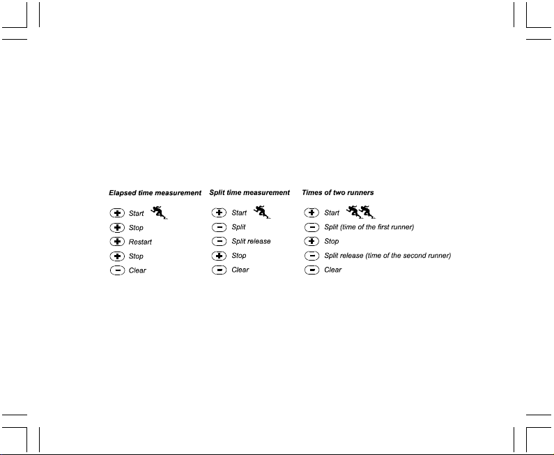
In the two finish time mode:
1. PRESS the [+] button to start the stopwatch in the stopwatch sub mode.
2. PRESS the [-] button once to stop the stopwatch to display the finish time of the first person.
3. PRESS the [+] button to stop the stopwatch.
4. PRESS the [-] button a second time to release and display the finish time of the second person.
5. PRESS the [-] button to clear and to reset the stopwatch.
Note: When the stopwatch function is activated, the stopwatch will continue and remain in the background if
the user is in other modes or sub modes. The user can identify the stopwatch is still activated by the flashing
text “stopwatch” in Field 3.
2.4 COUNTDOWN TIMER SUB MODE
In the TIME mode, PRESS the [Select] button three times to enter this sub mode.
In the countdown timer sub mode (Fig. 41):
• Field 1 displays the seconds,
• Field 2 displays the current time, and
• Field 3 displays the hours and minutes and to the bottom far right the text “timer”.
17
Page 18

2.4.1 How to Set the Countdown Timer
1. PRESS the [Select] button and hold in for 2 seconds. Located in Field 1, the seconds will begin to flash.
2. PRESS the [+] button to scroll the seconds upward or
PRESS the [-] button to scroll the seconds downward.
3. At the seconds desired, PRESS the [Select] button to move to the next setting. Located on right of Field 3,
the minutes will begin to flash.
4. PRESS the [+] button to scroll the minutes upward or
PRESS the [-] button to scroll the minutes downward.
5. At the minutes desired, PRESS the [Select] button to move to the next setting. Located in the center of Field
3, the hour will begin to flash.
6. PRESS the [+] button to scroll the hour upward or
PRESS the [-] button to scroll the hour downward.
7. At the hour desired, PRESS the [Mode] button to accept the changes and exit the setup program.
8. The countdown timer setup is complete.
2.4.2 How to Start the Countdown Timer
To start the countdown timer:
1. PRESS the [+] button to start, stop, and restart the timer in the countdown timer sub mode.
2. PRESS the [-] button to reset the timer to zero once the timer has stopped.
Note: When the countdown timer is activated, the countdown timer will continue and remain in the background
if the user is in other modes or sub modes. The user can identify the countdown timer still activated by the
flashing text “timer” in Field 3.
18
Page 19

2.5 DUAL TIME SUB MODE (ALTIMAX AND S-LANDER)
Note: This feature applies to the Altimax and S-Lander Wristop Computers
In the TIME mode, PRESS the [Select] button four times to enter this sub mode.
In the dual time mode (Fig. 42):
• Field 1 displays dUA indicating “dual time”,
• Field 2 displays the current time, and
• Field 3 displays the dual time (e.g. your home time).
The user can display the seconds while in this sub mode by pressing the [+] button, in Field 3 the seconds will
appear for 10 seconds. Afterwards the display returns back to showing the dual time.
2.5.1 Setting the Dual Time
In the dual time sub mode:
1. PRESS the [Select] button and hold in for 2 seconds. Located in Field 3, the hours will begin to flash.
2. PRESS the [+] button to scroll the hours upward or
PRESS the [-] button to scroll the hours downward.
3. At the hour desired, PRESS the [Select] button to move to the next setting. Located in Field 3 to the right of
the hour value, the minutes will begin to flash.
4. PRESS the [+] button to scroll the minutes upward or
PRESS the [-] button to scroll the minutes downward.
5. At the minutes desired, PRESS the [Mode] button to accept the changes and exit the setup program.
6. The dual time setup is complete.
The dual time stays the same, even though the time in the main time mode is adjusted. For example, if you set
the dual time to show your home time, your home time will always be displayed in this sub mode even though
you travel to a different time zone and adjust the time in the main time mode.
Note: The dual time function is completely independent and does not affect the alarms or the memory functions.
These are dependent of the current local time.
19
Page 20

CHAPTER 3 ALTIMETER MODE
The Altimeter mode provides the user with:
• an adjustable unit of measure either meter or feet: meter range -500 to 9,000; ft range -1,600 to 29,500;
• a resolution of 5m or 10ft;
• a display up-date on the rate of vertical movement in intervals of 1 second for 3 minutes, then every 10
seconds or less;
• an automatic 24-hour memory in one hour intervals showing altitude and vertical ascent/descent rate; and
• a logbook, recording approximately 3800 sets of data (one set = altitude, vertical ascent/descent rate and
time).
To view and use the Altimeter mode:
Check the Mode Indicator Bar. If the mode arrow is not on ALTI, PRESS the [Mode] button until the arrow is
directly below ALTI on the bar.
In the ALTIMETER mode (Fig. 1):
• Field 1 displays the vertical ascent or descent rate;
• Field 2 displays the current altitude in increments of 5 meters or 10 feet (depending on the unit of measure
selected); and
• Field 3 displays the current time.
• The Outer Circumference graphically displays the altitude in hundreds of meters or feet over a full thousand
where one complete circle is equivalent to 1000.
IMPORTANT NOTE: IN ORDER TO SET THE ALTITUDE IN THE ALTIMETER MODE, THE ALTITUDE MUST
BE KNOWN. THAT INFORMATION CAN BE FOUND BY UTILIZING A TOPOGRAPHICAL MAP, IDENTIFYING
THE CURRENT LOCATION WITH THE ASSOCIATED ALTITUDE MARKED. THE USER CAN PROCEED
AND FOLLOW THE INSTRUCTIONS, SETTING THE ALTIMETER, PROVIDED IN THE SECTION BELOW.
DETAILS REGARDING THE EFFECT OF AIR TEMPERATURE ON ALTITUDE MEASUREMENT ARE SHOWN
ON PAGE 41 OF THIS MANUAL.
20
Page 21

IF THE ALTITUDE IS NOT KNOWN, THE USER CAN SET THE SEA LEVEL PRESSURE IN THE BAROMETRIC
MODE (REFER TO PAGE 31, SETTING THE SEA LEVEL PRESSURE).
SETTING THE SEA LEVEL PRESSURE WILL ADJUST THE ALTIMETER TO THE CURRENT ALTITUDE
WITHIN SOME TEN METERS OR FEW HUNDRED FEET.
INFORMATION ON THE CURRENT SEA LEVEL PRESSURE CAN BE OBTAINED THROUGH NEWSPAPERS,
LOCAL NEWS AND RADIO WEATHER REPORTS, THE LOCAL AIRPORT FACILITY OR THROUGH THE
INTERNET UNDER LOCAL WEATHER.
3.1 SETTING THE ALTIMETER
In setting the Altimeter, there are three processes that can be performed:
• the Reference Altitude (known altitude at the current location),
• the Altitude Alarm (signifies the user when a certain altitude, programmed, is reached), and
• the Logbook Recording Interval (allows the user to view the altitude and rate of vertical movement within a
chosen interval of time).
To begin:
1. PRESS the [Select] button and hold in for 2 seconds. Located in Field 1 is the text “RE” (indicating reference
altitude), located in Field 2, the current altitude will begin to flash (Fig. 2).
2. PRESS the [+] button to scroll the altitude upward or
PRESS the [-] button to scroll the altitude downwards.
3. At the desired reference altitude, either PRESS the [Mode] button to accept the changes and return to the
main mode or PRESS the [Select] button to move to the next setting. Located in Field 1, the “ON” or “OFF”
will begin to flash (Fig. 3).
4. PRESS either the [+] or the [-] button to toggle between the “ON” and “OFF” for the Altitude Alarm.
5. At the desired setting, PRESS the [Select] button to move to the next setting. Located in the center of Field
2, the alarm altitude will begin to flash.
6. PRESS the [+] button to scroll the altitude upward or
PRESS the [-] button to scroll the altitude downwards.
21
Page 22

7. At the desired altitude, either PRESS the [Mode] button to accept the changes and return to the main mode
or PRESS the [Select] button to move to the next setting. Located in Field 1, the text INT and located in
Field 2 the time interval will begin to flash (Fig. 4).
8. PRESS either the [+] or the [-] button to scroll through the intervals. There are four time intervals 20 seconds,
1 minute, 10 minute or 60 minute.
Recommended interval to use:
Activity Interval
Skiing 20 sec or 1 minute
Biking 20 sec or 1 minute
Hiking 10 Minute
Mountaineering 10 minute or 60 minute
Note: In selecting the interval, the user chooses a) the time period for recording the altitude, the vertical ascent/
descent rate as well as the current time to be stored into the logbook and b) the timeout or maximum recording
time of a logbook. The shorter the interval the more accurate the information due to the fact the sampling rate
is faster. Timeouts are discussed on page 25.
9. At the desired interval, PRESS the [Mode] button to accept the changes and exit the setup program.
Once the user completes the process in setting the reference altitude of the current location to the known
altitude, the Wristop Computer will also correct the sea level pressure, and therefore, it will not be necessary for
this function to be set.
Note: If the user does not press any button for 1 minute in the setup mode, the display will automatically
exit setup.
Note: A 10-minute recording interval means that the Wristop Computer records data every 10 minutes.
22
Page 23

3.2 ALTITUDE DIFFERENCE MEASUREMENT SUB MODE
In the Altimeter mode, PRESS the [Select] button once to enter this sub mode.
In the Altitude Difference measurement sub mode (Fig. 13):
• Field 1 displays the vertical ascent or descent rate;
• Field 2 displays the current altitude in increments of 5 meters or 10 feet depending on the unit of measure
selected; and
• Field 3 displays the running time; to the left of the time is the text “differ”.
• The Outer Circumference graphically displays the altitude in hundreds of meters or feet over a full thousand
where one complete circle is equivalent to 1000.
The running time is displayed up to 39 hours and 59 minutes; after which three dashes (-:--) appear on the
display in Field 3. If the user allows the difference measurement sub mode to remain on visual display continuously
for 12 hours, the Wristop Computer will automatically return to the main time mode.
This mode does continue in the background and allows the user to move to other modes and at the convenience
of the user can return to this sub mode to display the current status.
Note: The difference measurement mode is a relative measurement. Any change in the reference altitude
during the altitude difference measurement will effect the measured altitude. We recommend that the reference
altitude always be checked and set again prior to beginning a new measurement.
3.2.1 How to Start the Altitude Difference Measurement
1. PRESS the [Select] button and hold in for 2 seconds. Located in Field 1 is the text “SET”; located in Field
2, zero will begin to flash (Fig. 14).
2. PRESS the [Mode] button to accept the flashing zero and start the difference measurement.
If the user does not desire to begin the difference measurement, PRESS either the [+] or the [-] button to toggle
to the current altitude then PRESS the [Mode] button to exit the setup program.
Note: If the user does not press any button for 1 minute in the setup mode, the display will return to the main
mode without zeroing the altimeter.
23
Page 24

3.3 24-HOUR MEMORY SUB MODE
In the Altimeter mode, PRESS the [Select] button twice to enter this sub mode.
In the 24-hour memory sub mode (Fig. 15):
• Field 1 displays the vertical ascent or descent rate;
• Field 2 displays the current altitude in increments of 5 meters or 10 feet depending on the unit of measure
selected; and
• Field 3 displays the particular hour and to the left the text “memory”.
• The Outer Circumference displays graphically the altitude in hundreds of meters or feet over a full thousand
where one complete circle is equivalent to 1000.
To view the information compiled in the 24-hr memory:
1. PRESS the [-] button to scroll back down in increments of one hour and view the vertical ascent/descent
rate and the altitude for that particular hour.
2. PRESS the [+] button to scroll back up.
Note: Replacing the battery will not erase this information.
3.4 LOGBOOK SUB MODE
In the Altimeter mode, PRESS the [Select] button three times to enter this sub mode. The logbook mode
features five displays. The displays automatically rotate showing the first display for 7 seconds then proceeds
showing displays 2 through 5 at 4 second intervals.
In the first display (Fig. 16):
• Field 1 displays the year;
• Field 2 displays the text “LO” with the current logbook number flashing; and
• Field 3 displays the month and day of the particular logbook number. To the left of the month/day, is the text
“Log Book”.
The user can PRESS the [-] to scroll down to view previous logs captured and then PRESS [+] to scroll up to the
current logbook.
24
Page 25

The second display shows the ascent information for the particular logbook that is being viewed (Fig. 17).
• Field 1 displays the average ascent rate during the event;
• Field 2 displays the total vertical ascent ; and
• Field 3 displays the text “ASC” along with the text “Log Book” to the left.
The third display shows the descent information for the particular logbook that is being viewed (Fig. 18).
• Field 1 displays the average descent rate during the event;
• Field 2 displays the total vertical descent; and
• Field 3 displays the text “dSC” along with the text “Log Book” to the left.
The fourth display shows the number of laps (runs; either ascents or descents) completed for the particular
logbook that is being viewed (Fig. 19).
• Field 2 displays the total number of ascents or descents ; and
• Field 3 displays the text “LAP” along with the text “Log Book” to the left.
Note: A Lap is a vertical movement either ascent or descent equaling 150 ft (50 meters) or above.
The fifth display shows the time duration of recording information in the particular logbook that is being viewed
(Fig. 20).
• Field 2 displays the total time of the log ; and
• Field 3 displays the text “dUr” along with the text “Log Book” to the left.
Note: If the logbook is recording, based on the interval chosen the logbook will record up to that particular time
period. Once the time period has been reached the Wristop Computer, will alert the user that the logbook
recording has expired (known as a timeout). For setting the logbook interval refer to Setting the Altimeter on
Page 21.
The timeouts are as follows: Logbook intervals Maximum recording time
20 second 10 hours
1 minute 12 hours
10 minute 7 days
60 minute 10 days
25
Page 26

3.4.1 How to Start and Stop a Logbook
For the Vector and X-Lander models:
In the Altimeter main mode or the difference measurement sub mode, PRESS the [+] button. A beep will be
heard and the flashing text “ Log Book” will appear in Field 3 to indicate the start of the recording.
Note: For the Vector and X-Lander models,while in the recording phase of the current logbook, the user will be
unable to view this data. The user can view this data only after the recording session has stopped, but previously
recorded logbooks can be viewed at any time.
The recording can be stopped by pressing the [+] a second time. A beep will be heard and the “Log Book” text
will be removed from Field 3 indicating recording has stopped.
Note: In order to prevent accidental starts/stops of a logbook, the Vector or X-Lander models should be in
another function other than the altimeter mode. If the logbook is activated the logbook will continue to recorded
even if the Vector or X-Lander is in another mode.
For the Altimax and S-Lander models:
Logbook recording starts by pressing the [+] button twice within 2 seconds. Logbook recording stops by
pressing the [+] button twice as well within 2 seconds.
Note: For the Altimax and S-Lander, Vector and X-Lander models logbooks are self-erasing and cannot be
cleared by the user.
Note: If you desire greater precision, start new logbooks more often or lower the recording interval.
3.4.2 Fast Cumulative Button
This function is furnished in the Altimax and S-Lander models. This allows the user to check the cumulative
vertical ascent/descent in feet or meters, as well as number of runs of the current logbook while recording.
Accessing this information is performed by pressing the [-] button in any of the main modes. When activated,
three displays will automatically rotate in intervals of four seconds.
• The first display shows the accumulative vertical ascent since the beginning of the current logbook.
• The second display shows the accumulative vertical descent since the beginning of the current logbook.
• And finally, the third display shows the number of runs accomplished during the current logbook.
26
Page 27

After the third display is shown, the Altimax and S-Lander automatically return to the main mode in which the
user was viewing.
Note: During this process, pressing the [-] button allows the user to move on to the next of the three displays.
3.5 LOGBOOK HISTORY SUB MODE
The Logbook history shows a summation of all logs recorded.
In the Altimeter mode, PRESS the [Select] button four times to enter this sub mode. The logbook history mode
features four displays.
In the first display (Fig. 24):
• Field 1 displays the year when the logbook history has been last cleared;
• Field 2 displays the text “HIS”; and
• Field 3 displays the month and day when the logbook history has been last cleared. To the left of the month/
day, displayed is the text “Log Book”.
PRESS [+] to scroll through the different displays.
In the second display (Fig. 25):
• Field 1 displays the text “HI”;
• Field 2 displays the highest altitude recorded since the last date cleared; and
• Field 3 displays the date when it was reached with the text “Log Book” to the left.
In the third display (Fig. 26):
• Field 1 displays the text “ASC”;
• Field 2 and 3 show up to an 8 digit accumulative vertical ascent since the last reset. Field 2 is activated
when the value of the vertical ascent is beyond the 3 digit value displayed in Field 3.
In the fourth display (Fig. 27):
• Field 1 displays the text “dSC”;
• Field 2 and 3 show up to an 8 digit accumulative vertical descent since the last reset. Field 2 is activated
when the value of the vertical ascent is beyond the 3 digit value displayed in Field 3.
27
Page 28

3.5.1 Clearing the Logbook History
To clear the history of the logbook (Fig. 28):
1. In any of the logbook history displays, PRESS the [Select] button and hold in for 2 seconds. Located in
Field 1 is the text “CLR”; in Field 2 the text “HIS”; and in Field 3, “nO” will begin to flash.
2. PRESS the [+] button to toggle between “YES” and “NO”.
3. PRESS the [Mode] button to accept the option “YES”.
The logbook history is erased and a new starting date is set to begin new cumulative measurements.
Note: If the user does not press any button for 1 minute in the setup mode, the display will automatically
exit setup.
We recommend that the logbook history be cleared prior to beginning logbook recording(s).
CHAPTER 4 BAROMETER MODE
The Barometer mode provides the user with:
• an adjustable unit of measure mbar or inHg; mbar range 300 to 1 100 mbar, inHg range 8.90 to 32.40;
• a resolution of 1 mbar or 0.05 inHg;
• a one hour interval measuring to estimate barometric trend;
• an automatic 4-day memory of atmospheric pressure for the last 6 hours in 1-hour intervals, thereafter, in 6hour intervals;
• temperature compensation (temperature does not effect the pressure within the specified temperature
range)
• a temperature range -20O to 60OC or -5O to 140OF; and
• a temperature resolution of 1
Note: Body heat will effect temperature when the Wristop Computer is worn on the wrist. To achieve an
accurate reading remove the Wristop Computer from the wrist and allow at least 15 minutes before reading
the temperature.
If you’ve been in the barometric mode for more than 15 minutes with no rate of vertical movement, you should
O
C or F.
28
Page 29

allow 1 hour for the Wristop Computer to adjust the temperature. To acquire a quicker up-date of the temperature,
press the [Mode] button 4 times to re-enter the mode.
To view and use the Barometer mode:
Check the Mode Indicator Bar. If the mode arrow is not on BARO, PRESS the [Mode] button until the arrow is
directly below BARO on the bar.
In the Barometer mode (Fig. 5):
• Field 1 displays the current temperature.
• Field 2 displays the current absolute atmospheric pressure.
• Field 3 displays the current time.
• The Outer Circumference graphically displays the atmospheric pressure over 100 millibars or 1 inHg where
one complete circle is equivalent to 100 mbar/1 inHg, depending on the unit of measure chosen.
Note: The absolute pressure is the actual pressure in any location at any given time. Where as, sea level
pressure is the corresponding pressure at sea level.
4.1 PRESSURE DIFFERENCE MEASUREMENT SUB MODE
The pressure difference is not referring to the sea level pressure, but to the current barometric pressure
measured by the watch.
In the Barometer mode, PRESS the [Select] button once to enter this sub mode.
In the Pressure Difference Measurement submode (Fig. 30):
• Field 1 displays the change in temperature.
• Field 2 displays the change in atmospheric pressure.
• Field 3 displays the current time; to the left of the time is the text “differ”.
• The Outer Circumference graphically displays the change in pressure where one full circle equals 100
mbars or 1 inHg.
This mode does continue in the background and allows the user to move to other modes and at the user’s
convenience can return to this sub mode to show the current reading.
29
Page 30

4.1.1 How to Start the Pressure Difference Measurement
1. PRESS the [Select] button and hold in for 2 seconds. Located in Field 1 is the text “SET”; located in Field
2, zero will begin to flash (Fig. 29).
2. PRESS the [Mode] button to accept the flashing zero and start the difference measurement.
If the user does not desire to begin the difference measurement, PRESS either the [+] or the [-] button to toggle
to the current barometric pressure reading, then PRESS the [Mode] button to exit the setup program.
Note: If the user does not press any button for 1 minute in the setup mode, the display will automatically exit
setup.
4.2 4-DAY MEMORY SUB MODE
In the Barometer mode, PRESS the [Select] button twice to enter this sub mode. This function allows the user
to follow changes in pressure that will assist forecasting changes in weather condition (i.e. storms).
In the 4-day memory sub mode (Fig. 31):
• Field 1 displays the day of the week the user is in;
• Field 2 displays the atmospheric pressure; and
• Field 3 displays the time and to the left the text “memory”.
• The Outer Circumference graphically displays the atmospheric pressure where one full circle equals
100 mbars or 1 inHg.
To view the information compiled in the 4-day memory:
PRESS the [-] button to scroll back down in increments of one hour for the first six hours, after that increments
are 6 hours.
PRESS the [+] button to scroll back up.
Note: Replacing the battery will not erase this information.
30
Page 31

4.3 SEA LEVEL PRESSURE SUB MODE
Sea level pressure is pressure relative to sea level where as the pressure read in the main barometric display
is absolute pressure in the current location.
In the Barometer mode, PRESS the [Select] button three times to enter this sub mode.
In the sea level pressure sub mode (Fig. 32):
• Field 1 displays the text “SEA”;
• Field 2 displays the current sea level pressure; and
• Field 3 displays the current time.
4.3.1 Setting the Sea Level Pressure
Setting the sea level pressure can be used in setting the altitude measurement on the Wristop Computer if the
altitude is not known.
To set the sea level pressure:
1. PRESS the [Select] button and hold in for 2 seconds. Located in Field 2, the current sea level pressure will
begin to flash.
2. PRESS the [+] button to scroll the pressure upward or
PRESS the [-] button to scroll the pressure downward.
3. At the desired pressure, PRESS the [Mode] button to accept the changes and return to the main mode.
Once the user completes this process, the altitude measurement on the Wristop Computer is correct within a
range of some ten meters or few hundred feet.
Note: Information on the current sea level pressure can be obtained through newspapers, local news and radio
weather reports, the local airport facility or through the Internet under local weather.
If the user does not press any button for 1 minute in the setup mode, the display will automatically exit setup.
31
Page 32

4.4 BAROMETRIC TREND INDICATOR
Located on the top left corner of the LCD display resides the Barometric Trend Indicator. This feature is always
displayed in all main modes providing the user a continual quick reference to analyze upcoming weather
conditions.
The Barometric trend is comprised of two lines forming an arrow. Each line represents a 3-hour period. The
right line represents the last 3 hours. The left line represents 3 hours prior to the last 3 hours. The line can
indicate 9 different patterns in the barometric trend.
Situation 6-3 hours ago Situation last 3 hours
Dropped heavy (>2 mbars/3hours) Dropping heavy (>2 mbars/3hours)
Dropped heavy (>2 mbars/3hours) Remaining stable
Dropped heavy (>2 mbars/3hours) Rising heavy (>2 mbars/3hours)
Remained stable Dropping heavy (>2 mbars/3hours)
Remained stable Remaining stable
Remained stable Rising heavy (>2 mbars/3hours)
Risen heavy (>2 mbars/3hours) Rising heavy (>2 mbars/3hours)
Risen heavy (>2 mbars/3hours) Remaining stable
Risen heavy (>2 mbars/3hours) Dropping heavy (>2 mbars/3hours)
Note: If the user remains at the same elevation, the barometric trend indicator can work as a weather forecasting
tool.
CHAPTER 5 COMPASS MODE (VECTOR AND X-LANDER)
Note: This function applies to the Vector and X-Lander.
The compass mode provides the user with:
• a cardinal or half cardinal point abbreviation;
32
Page 33

• bearing degrees;
• a North-South arrow;
• a bearing track mode showing desired direction and actual bearing;
• a bubble level for accuracy reading
• a rotating bezel;
• a resolution of 1° for the bearing,
• a declination correction feature.
To view and use the Compass Mode:
Check the Mode Indicator Bar. If the mode arrow is not on COMP, PRESS the [Mode] button until the arrow is
directly below COMP on the bar.
In the COMPASS mode (Fig. 6):
• Field 1 displays the cardinal or half-cardinal point.
• Field 2 displays the bearing in degrees.
• Field 3 displays the current time.
• The Outer Circumference graphically displays the North-South arrow where one-lit segment shows North
and three-lit segments show South.
The Wristop Computer provides a bubble level for the user to achieve a precise reading within
user should acquire a bearing by removing the Wristop Computer from the wrist. The user centers the liquid
bubble to ensure the Wristop Computer position is level and takes a reading.
The compass display is active for 45 seconds at a time. After this, the compass enters “sleep” mode and an “-
--°” indicator appears in the field 2. Reactivate the compass by pressing the [-] button.
Note: Compass readings should be performed away from objects possessing sources of magnetism. Avoid
buildings, large metal objects, power lines, loudspeakers, electric motors etc.
Always take bearings in the open air, not inside tents, caves, or other shelters.
+3 degrees (only in the Vector);
+5° for North-South direction; and
+3 degrees. The
33
Page 34

5.1 BEARING TRACKING SUB MODE
The user can select to change from the cardinal point mode to the bearing track function and utilize the bearing
lock function in this mode for tracking purposes (Fig. 7).
In the compass main mode:
1. PRESS the [Select] button and hold in for 2 seconds. Located in Field 1, “OFF” will begin to flash (Fig. 8).
2. PRESS either the [+] or the [-] button to change the setting between “OFF” and “ON”.
3. At the selection desired, PRESS the [Select] button to move to the next setting. Located in Field 2, the
actual bearing in degrees will begin to flash (Fig. 9).
4. Turn the Wristop Computer to the desired direction. Lock the bearing displayed by pressing the [-] button.
5. Adjust the locked bearing, if necessary by pressing the [Select] button and then adjusting the value with the
[+] and [-] buttons.
6. At the desired bearing to track, PRESS the [Mode] button to accept the changes and exit the setup program.
Note: If the user does not press any button for 1 minute in the setup mode, the display will automatically exit
setup.
Note: Locking in the Bearing Tracking submode blocks the compass reading.
5.2 DECLINATION ADJUSTMENT SUB MODE
The Wristop Computer allows the user to compensate the difference between true north and magnetic north.
This process is accomplished by adjusting the declination, resulting in the user obtaining correct compass
readings.
In the Compass mode, PRESS the [Select] button once to enter this sub mode.
In the Declination Adjustment sub mode (Fig. 33):
• Field 1 displays the declination direction “OFF” where
OFF = no declination; W = West; E = East.
• Field 2 displays declination in degrees.
• Field 3 displays the text “dEC”.
34
Page 35

5.2.1 Setting the Local Declination
1. PRESS the [Select] button and hold in for 2 seconds. Located in Field 1, “OFF” will begin to flash.
2. PRESS either the [+] or the [-] button to change the declination direction in Field 1.
3. At the direction desired, PRESS the [Select] button to move to the next setting. Located in Field 2, the
degrees will begin to flash.
4. PRESS the [+] button to scroll the degrees upward or
PRESS the [-] button to scroll the degrees downward.
5. At the degrees desired, PRESS the [Mode] button to accept the changes and exit the setup program.
Note: If the user does not press any button for 1 minute in the setup mode, the display will automatically exit
setup.
Local Declination is now set.
5.3 CALIBRATING THE COMPASS
A compass calibration should be done when the Wristop Computer is subject to close proximity of magnetic
sources, extreme cold weather, every time the battery is replaced or suspected that other environmental conditions
have effected the compass readings.
Note: We also recommend calibrating the compass before using the compass the first time and every time
leaving for a hike where the compass will be used.
To begin the calibration:
1. PRESS the [Select] button twice when in the main compass mode. Field 1 displays the text “CMP”. Field 3
displays the text “CAL” (Fig. 34).
2. PRESS the [Select] button and hold in for 2 seconds. Located in Field 2, the text “PUSH” will begin to flash
(Fig. 35).
3. PRESS the [-] button to start calibration.
4. In Field 2, 360° appears and the Outer Circumference displays all segments lit (Fig. 36). When this occurs,
hold the Wristop Computer level and start to slowly turn the device around a full circle in a level position. The
35
Page 36

direction of turning does not matter. The lit segments will be turned off as the turning proceeds. When the
first full circle is completed, the instrument will inform the user within one minute of whether the calibration
was successful displaying the text “dOnE” in Field 2 (Fig. 37) or if the process needs to be repeated
displaying “PUSH” and “-” in Field 2.
Note: The user may need to perform the rotating of the compass more than twice around for the calibration to
be completed.
Note: During calibration, it is not necessary that all peripheral segments light up or turn off.
Note: If the text “FAIL” appears in Field 2 (Fig. 38), the battery should be removed and put back in before trying
to proceed with the calibration process. The removal of the battery will “reset” the unit.
5. Once the calibration is successful, PRESS the [Mode] button to accept the process and exit the calibration
mode.
Note: It is important to hold the Wristop Computer level during the calibration process to ensure accuracy.
The compass calibration is complete.
CHAPTER 6 FREQUENTLY ASKED QUESTIONS
6.1 GENERAL
6.1.1 Is the Wristop Computer water resistant?
Yes, it is water resistant to a depth of 30 meters (100 ft). Rain and other normal exposure to water will not effect
its operation. You can swim wearing your Wristop Computer. However, the Wristop Computer is NOT a diving
device.
6.1.2 How long will the battery last?
All users employ the product in different ways. Battery life depends mainly on how much the backlight, the
compass and the logbook are used. The low-battery warning symbol appears on the display when 5 to 15
percent of battery capacity remains. This should give the user plenty of time to safely change the battery.
36
Page 37

6.1.3 What do the segments on the circumference mean?
In the Altimeter mode, one full circle equals 1,000 meters or 1,000 feet, therefore the segments on the
circumference graphically show the user the altitude over a full thousand. When using the difference measurement
function of the altimeter, the segments indicate the vertical difference in the elevation over a full thousand
either to the right if you’re ascending or to the left if you’re descending.
In the Barometer mode, one full circle equals 100 mbar or 1 inHg, and the segments indicate the pressure over
a full hundred mbar or over a full inHg. When using the difference measurement function of the barometer, the
segments indicate the change in atmospheric pressure either to the right if the pressure has risen or to the left
if the pressure has dropped.
In the main Compass mode, the segments indicate the North, i.e. the one segment indicates North and the
three segments point South. If you have set the compass to track a certain bearing, the segments on the
circumference indicate the difference between the direction in which you want to go and your actual bearing.
6.1.4 Why do the segments on the circumference go to the left
(counterclockwise)?
Normally, they always go to the right (clockwise) from the 12-noon position.
You are in the difference measurement mode and your unit is showing a decreasing value. In normal mode,
the segment display increases clockwise, but if you are in a mode that shows you differences (such as vertical
ascent/descent), all decreasing values go counterclockwise from the center position, and all increasing values
go clockwise. So, it is “minus” to the left (counterclockwise), and “plus” to the right (clockwise).
6.1.5 Why are there two symbols above the Mode Indicator Bar
and what do they mean?
The left-hand symbol indicates that the altitude alarm is activated and the right-hand symbol indicates that
one, two, or three daily alarms are activated.
37
Page 38

6.2 TIME
6.2.1 Why do the segments on the circumference increase and
decrease when I am in the Time mode?
The main function of the segments is related to the Compass mode, where a division into 36 segments is
necessary due to the 360-degree scale of a compass. In the Time mode, the segments show the advancement
of seconds. Because the number of seconds differs from the number of degrees, it is impossible for the segments
to be consecutively lit up; they now light up or extinguish, thereby marking the passing of every second.
6.2.2 What is the longest time I can set in the timer?
The maximum range of the countdown timer is 23 hours 59 minutes and 59 seconds.
6.3 ALTIMETER
6.3.1 How do you clear the logbook?
The logbook is self-erasing and cannot be cleared by the user.
6.3.2 How does the logbook self-erase?
The logbook is circular and will start erasing itself when all the memory places are filled. There are approx.
3,800 memory places, each of which contain the altitude as well as the ascent/descent rate at that time (according
to the chosen interval, 20 seconds, 1 minute, 10 or 60 minutes).
When all the memory places are filled, the logbook starts recording new logs on top of the oldest recordings.
This is what is meant when we say the logbook is “self-erasing”.
You can clear the history of the logbook; i.e. where you get the cumulative ascent and descent information
based on the logs recorded into the logbook.
6.3.3 How many logbooks can you record?
The number of logs you can record into the logbook depends on the chosen interval and the length of each log.
For example, if your interval is 1 minute, you can get a total of 3,800 minutes of logs into the logbook. This
equals 2.64 days if the recording is continuous (24 hours = 1,440 minutes; 3,800/1,440=2.64).
38
Page 39

To avoid excessive battery drain, the recording is not continuous. The recording functions have certain timeouts
(i.e. the recording will be turned off automatically after a certain time). The timeouts are shorter for the faster
interval and longer for the slower interval.
6.3.4 What is the duration readout?
The duration readout tells you how many hours and/or minutes the event recorded into the logbook lasted. For
example, if you’re hiking from 1 p.m. to 6 p.m. and the logbook is on during this time, the readout would show
a duration of 05:00 hours.
6.3.5 What is the maximum capacity of total vertical ascent or
descent feet/meters in the logbook history?
The maximum figure that can be shown on the display is 29,999.999 representing feet or meters depending on
the unit of measurement set. This should be enough for most users: 29,999.999 meters is roughly threequarters around the globe.
6.3.6 If hiking from a level of 5,000 ft down hill to 3,000 ft and
then back up to 8,000 feet, how is the Vector going to read this or
average it out?
There are several answers to this question related to different situations.
First, if you mean will Wristop Computer show accurate altitude information when ascending back to 8,000 ft
after having descended to 3,000 ft from 5,000 ft, the answer is yes if the barometric pressure hasn’t been
affected by weather changes. Since the altitude is shown based on the atmospheric pressure reading it will be
affected by pressure changes. But if the conditions are the same, and the reference altitude is set, the unit will
show quite accurate readings.
Second, if what you mean is how the Wristop Computer calculates the information shown in the logbook, this
is what it does: for the total ascent during the log (the logbook recording has been activated by the user when
starting out) it calculates the ascent from 3,000 ft to 8,000 ft, i.e. total ascent has been 5,000ft. For the descent
it calculates the descent from 5,000 ft to 3,000 ft, i.e. total descent 2,000 ft.
39
Page 40

Third, if thinking about the difference measurement function and how this is affected by the example situation,
the Wristop Computer will show you the absolute difference between 5,000 ft and 8,000 ft (beginning and
end). The fact that you’ve been down to 3,000 ft in-between does not have an impact on the absolute vertical
altitude difference between starting point and finish.
Last, the automatic 24-hour memory will show this information in the following way: Say you are starting out
at 5,000 ft at noon, and then it takes you 2 hours to descend to 3,000 ft, and another five hours to reach 8,000
ft. The scrollable displays in the 24-hour memory shows you the altitude 5,000 ft at 12:00 am, e.g.4,000 ft at 1
p.m., 3,000 ft at 2 p.m., e.g. 4,000 ft 3 p.m., 5,000 ft at 4 p.m., 6,000 ft at 5 p.m., 7,000 ft at 6 p.m. and then 8,000
ft at 7 p.m.
These are the different cases in which the example situation will affect the readings of the Wristop Computer.
Most important to remember is to ALWAYS set the known reference altitude into the Wristop Computer. This is
the only way to get accurate altitude readings.
6.3.7 Why does the vertical ascent/descent measurement show
different readings even though I am inside and staying in the
same room?
The resolution of the vertical ascent/descent rate is 1 m/1 ft whereas the resolution of the altitude display is 5
m/10 ft, which means that the ascent/descent rate can show movement even though you remain at the same
altitude. This is caused by changes in pressure or even vertical movement within the 5 m/10 ft resolution range.
Indoors, even small, unnoticeable air currents cause changes in air pressure. For example, if you have a
window open at the other end of your house, the air current may affect a room at the other end of the building
so little that you do not notice it, but the sensors of the Wristop Computer do. Because the Wristop Computer
measures ascent and descent based on changes in air pressure, it interprets these changes as vertical movement.
6.4 BAROMETER
6.4.1 What is the little box on the top left of the display?
It is the barometric trend indicator that shows the general direction of weather changes. The display is based
on barometer measurements for the last 6 hours.
40
Page 41

6.4.2 Does the Wristop Computer show future trends in weather
conditions?
No, the Wristop Computer continually accumulates data on barometric pressure existent within a 3 to 6 hour
window and displays general barometric trends in weather based on the accumulated data.
6.4.3 What does “absolute pressure” and “relative pressure”
mean?
Absolute pressure is the actual pressure in any location at any given time. Relative pressure on the other hand
equals the corresponding pressure at sea level for a certain altitude that you are at. For example, if you are at
an altitude of 1,000 m/3,300 ft the absolute pressure normally is around 900 mbar/26.60 inHg. The relative
pressure at sea level would then be around 1,013 mbar/29.90 inHg.
6.4.4 What is temperature compensation?
When the unit is temperature compensated, the altitude measurement of the unit is not affected by the
temperature of the unit itself. The unit can be worn on your wrist or placed on a table – it will in either case give
you the proper altitude reading providing the weather conditions have not changed. All Suunto Wristop Computers
are temperature compensated within the range –5 to 140 ° F / - 20 to +60 ° C.
6.5 COMPASS
6.5.1 What is the purpose of the rotating outer bezel?
The purpose of the rotating bezel is that people can use the instrument as a regular base plate compass if they
want to, and use the bezel to e.g. indicate North when in the bearing tracking mode or leaving the compass
display for another mode.
Also, it can be used to manually follow your vertical progress by using the lubber's line on the bezel to mark the
altitude from where you want to follow your progress (i.e. a zero point). You could also mark a certain altitude,
which is graphically shown by the segments on the circumference, to get an intermediate difference
measurement. However, the bezel is mainly related to the compass function.
41
Page 42

6.5.2 Where do I find the correct declination for my area so I can
set my Wristop Computer?
Local declination, either E or W, is usually marked on maps with either one-degree or half-degree accuracy.
6.6 EFFECT OF AIR TEMPERATURE ON ALTITUDE
MEASUREMENT
The atmospheric pressure means the weight of air mass above the observer: at a higher altitude there is less
air than at a lower altitude. The principle of an altimeter is to measure the different air pressure between
different altitudes.
The air weight is affected by the outside temperature. Consequently the air pressure difference between two
altitudes is also dependant on temperature.
The altitude calculation of Wristop Computer is based on the air pressure at certain normal temperatures. Each
altitude has a definitive normal temperature. The normal temperatures at each altitude are presented in table 1.
Altitude (m) Altitude (ft) Temperature (C) Temperature (F)
above sea level above sea level
0 0 15.0 59.0
200 656 13.7 56.7
400 1312 12.4 54.3
600 1969 11.1 52.0
800 2625 9.8 49.6
1000 3281 8.5 47.3
1200 3937 7.2 45.0
1400 4593 5.9 42.6
1600 5250 4.6 40.3
42
Page 43

1800 5906 3.3 37.9
2000 6562 2.0 35.6
2400 7874 -0.6 30.9
2800 9187 -3.2 26.2
3000 9843 -4.5 23.9
3400 11155 -7.1 19.2
3800 12468 -9.7 14.5
4000 13124 -11.0 12.2
4500 14765 -14.3 6.4
5000 16405 -17.5 0.5
5500 18046 -20.8 -5.4
6000 19686 -24.0 -11.2
Table 1. Normal temperatures corresponding to different altitudes
Now the altitude measurement error caused by an abnormal temperature gradient can be approximated as
follows. If the sum of the temperature offsets from the normal temperatures determined at two different
altitudes is 1 ºC, the altitude difference calculated by Wristop Computer is 0.2% off the real altitude
difference (When using imperial units the offset factor is 0.11% / 1 ºF). This is because the real temperatures
are not always the same as the normal temperatures. A higher than normal temperature causes the calculated
altitude difference to be smaller than the real altitude difference (your mountain ascent was actually higher).
Consequently, a lower than normal temperature causes the calculated altitude difference to be larger than the
real altitude difference (you did not ascend quite as high as displayed).
Table 2 shows an example in which the temperature offsets are positive. In this example, the reference altitude
is set at 1000 m. At 3000 m the altitude difference is 2000 m and Wristop Computer shows 80 m too little (20
ºC * 2000 m * 0.002/ºC = 80 m). Your actual altitude is thus 3080 m.
43
Page 44

Set reference altitude (real altitude) 1000 m
Displayed altitude 3000 m
Real outside temperature +17.5 ºC +6.5 ºC
Normal (table) temperature +8.5 ºC -4.5 ºC
Temperature offset (= real - normal) +9 ºC +11 ºC
Sum of temperature offsets +9 ºC + +11 ºC = 20 ºC
Table 2. Example using meters and Celsius
Table 3 shows an example in which the temperature offsets are negative This time imperial units are used.
The reference altitude is set at 3280 feet. At 9840 feet the altitude difference is 6560 feet and Wristop Computer
shows 100 feet too much (-14 ºF * 6560 ft * 0.0011/ºF = -100 ft). Your actual altitude is thus 9740 ft.
Set reference altitude (real altitude) 3280 ft
Displayed altitude 9840 ft
Real outside temperature +36.3 ºF +18.9 ºF
Normal (table) temperature +47.3 ºF +23.9 ºF
Temperature difference (= real - normal) -9 ºF -5 ºF
Sum of temperature offsets -9 ºF + -5 ºF = -14 ºF
Table 3. Example using feet and Fahrenheit.
Lower point Higher point
Lower point Higher point
CHAPTER 7 SPARE PARTS AVAILABLE
Battery Replacement Kit (including battery, battery lid and o-ring)
Watch Straps in plastic (Vector/Altimax) or leather, velcro fabric and textile (S-Lander/X-Lander)
Extension strap in plastic
Bezel (Available only in Suunto Oy during maintenance)
Suunto Oy provides moderate-priced Wristop Computer service to its customers.
Batteries are usually available in sport and watch shops etc.
44
Page 45

CHAPTER 8 ABBREVIATIONS
dEF - default factory setting of pressure sensor,
corresponds to standard (1013 mbar or 29,90
inHg) airpressure at sea level
SNR - sensor (used in sensor calibration)
RE - reference altitude
CLR - clear
ASC - ascent
dSC - descent
bEG - begin
HIS - history
dUA - dual time
dUR - duration
CMP - compass
CAL - calibration
bEA - bearing
CHAPTER 9 COPYRIGHT AND TRADEMARK NOTICE
This publication and its contents are proprietary to Suunto Oy and are intended solely for the use of its clients
to obtain knowledge and key information regarding the operation of all or any Wristop Computer product(s)
that includes the Vector, the X-Lander, the S-Lander and the Altimax.
Its contents shall not be used or distributed for any other purpose and/or otherwise communicated, disclosed
or reproduced without the prior written consent of Suunto Oy.
Suunto, Wristop Computer, Vector, X-Lander, Slander, Altimax and their logos are all registered or unregistered
trademarks of Suunto Oy. All rights are reserved.
While we have taken great care to ensure that information contained in this documentation is both comprehensive
and accurate, no warranty of accuracy is expressed or implied.
CHAPTER 10 CE COMPLIANCE
All Suunto Wristop Computers conform with the required European Union EMC directives 89/336/TEC.
45
Page 46

CHAPTER 11 LIMITS OF LIABILITY AND ISO 9001
COMPLIANCE
If this product should fail due to defects in materials or workmanship, Suunto Oy will, at its sole option, repair or
replace it with new or rebuilt parts, free of charge, for two (2) years from the date of its purchase. This warranty
is extended only to the original purchaser and only covers failures due to defects in materials and workmanship
that occur during normal use while in the period of the warranty.
It does not cover damage or failures resulting in accident, misuse, neglect, mishandling, alteration or modifications
of the product, or any failure caused by operation of the product outside the scope of its published specifications,
or any causes not covered by this warranty.
There are no express warranties except as listed above.
Suunto Oy, Suunto Europe and Suunto USA/Canada shall in no event be liable for any incidental or consequential
damages arising from the use of or inability to use the product. Suunto Oy does not assume any responsibility
for losses or claims by third parties which may arise through the use of this device.
Suunto’s Quality Assurance System is certified by Det Norske Veritas to be ISO 9001 compliant in all SUUNTO
Oy’s operations (Quality Certificate No. 96-HEL-AQ-220).
CHAPTER 12 DISPOSAL OF THE DEVICE
Please dispose of the device in an appropriate way, treating it as electronic waste. Do
not throw it in the garbage. If you wish, you may return the device to your nearest Suunto
representative.
46
Page 47

GUIDE DE L’UTILISATEUR
COORDONNÉES DU SERVICE CLIENTS
Suunto Oy Tél. +358 9 875870
Fax +358 9 87587301
Suunto USA Tél. 1 (800) 543-9124
Canada Tél. 1 (800) 776-7770
Centres d'appels en Europe Tél. +358 2 284 11 60
Site Web Suunto
www.suunto.com
1
FR
Page 48

TABLE DES MATIÈRES
CHAPITRE 1 INTRODUCTION .......................................................... 6
1.1 INFORMATIONS GÉNÉRALES ................................................................................... 6
1.2 MODES (FONCTIONS PRINCIPALES) ....................................................................... 6
1.2.1 Rétro-éclairage .............................................................................................. 7
1.2.2 Étanchéité ..................................................................................................... 7
1.3 FONCTIONS DES BOUTONS ..................................................................................... 7
1.3.1 Bouton [Mode] ............................................................................................... 7
1.3.2 Bouton [+] ...................................................................................................... 8
1.3.3 Bouton [-] ....................................................................................................... 8
1.3.4 Bouton [Select] .............................................................................................. 8
1.4 ÉCRAN LCD ................................................................................................................ 8
1.5 MESURES ET UNITÉS .............................................................................................. 10
1.5.1 Sélection des unités de mesure .................................................................. 10
1.6 ÉTALONNAGE DU CAPTEUR DE PRESSION .......................................................... 11
1.7 ENTRETIEN ...............................................................................................................11
1.7.1 Changement de la pile ................................................................................ 12
CHAPITRE 2 MODE MONTRE (TIME) ............................................. 13
2.1 RÉGLAGE DE L’HEURE ............................................................................................ 13
2.2 FONCTION ALARME JOURNALIÈRE ....................................................................... 15
2.2.1 Réglage des alarmes journalières .............................................................. 15
2.3 FONCTION CHRONOMÈTRE ................................................................................... 16
2.3.1 Utilisation du chronomètre .......................................................................... 16
2.4 FONCTION COMPTE À REBOURS .......................................................................... 17
2.4.1 Réglage du compte à rebours ..................................................................... 18
2
Page 49

2.4.2 Mise en route du compte à rebours ............................................................. 18
2.5 FONCTION HEURE D’UN DEUXIÈME FUSEAU HORAIRE (ALTIMAX, S-LANDER) 19
2.5.1 Réglage de l’heure d’un deuxième fuseau horaire ...................................... 19
CHAPITRE 3 MODE ALTIMÈTRE (ALTI) ......................................... 20
3.1 RÉGLAGE DE L’ALTIMÈTRE ..................................................................................... 21
3.2 FONCTION MESURE DE DÉNIVELÉ ........................................................................ 23
3.2.1 Activation de la fonction mesure de dénivelé............................................... 23
3.3 FONCTION MÉMOIRE 24 HEURES .......................................................................... 24
3.4 FONCTION JOURNAL .............................................................................................. 24
3.4.1 Mise en route et arrêt d’un journal ............................................................... 26
3.4.2 Bouton de cumul rapide .............................................................................. 26
3.5 FONCTION HISTORIQUE DU JOURNAL ................................................................. 27
3.5.1 Effacement de l’historique du journal .......................................................... 28
CHAPTER 4 MODE BAROMÈTRE (BARO) ...................................... 28
4.1 FONCTION MESURE DE DIFFÉRENCE DE PRESSION ......................................... 29
4.1.1 Activation de la fonction mesure de différence de pression........................ 30
4.2 FONCTION MÉMOIRE 4 JOURS .............................................................................. 30
4.3 FONCTION PRESSION RÉDUITE AU NIVEAU DE LA MER .................................... 31
4.3.1 Réglage de la pression réduite au niveau de la mer .................................. 31
4.4 INDICATEUR DE TENDANCE BAROMÉTRIQUE ..................................................... 32
CHAPITRE 5 MODE BOUSSOLE (COMP) (VECTOR ET X-LANDER) 33
5.1 FONCTION SUIVI DE CAP ........................................................................................ 34
5.2 FONCTION CORRECTION DE DÉCLINAISON ....................................................... 35
5.2.1 Réglage de la déclinaison locale ................................................................. 35
5.3 ÉTALONNAGE DE LA BOUSSOLE ........................................................................... 36
3
Page 50

CHAPITRE 6 FOIRE AUX QUESTIONS ........................................... 37
6.1 GÉNÉRALITÉS .......................................................................................................... 37
6.1.1 Mon ordinateur de poignet est-il étanche ? ................................................. 37
6.1.2 Combien de temps la pile dure-t-elle ? ....................................................... 37
6.1.3 Que représentent les segments de l’affichage circulaire ?......................... 37
6.1.4 Pourquoi les segments de l’affichage circulaire vont-ils vers la gauche
(sens inverse des aiguilles d’une montre) ? ......................................................... 38
6.1.5 Pourquoi y a-t-il deux symboles au-dessus de l’indicateur de mode et que
6.2 MONTRE ................................................................................................................... 38
6.3 ALTIMÈTRE ............................................................................................................... 39
6.4 BAROMÈTRE ............................................................................................................ 41
signifient-ils ? .............................................................................................. 38
6.2.1 Pourquoi les segments de l’affichage circulaire augmentent et diminuent
lorsque le mode TIME est activé ? ............................................................. 38
6.2.2 Quelle est la durée maximale du compte à rebours ? ................................. 38
6.3.1 Comment puis-je effacer le journal ? .......................................................... 39
6.3.2 Comment le journal s’efface-t-il de lui-même ? ........................................... 39
6.3.3 Combien de journaux puis-je enregistrer ? ................................................. 39
6.3.4 Qu’est-ce que l’affichage de la durée ? ....................................................... 39
6.3.5 Quelle est la capacité maximale de montée/descente totale (en mètres ou en
pieds) que l’historique du journal peut enregistrer ? ................................... 40
6.3.6 Si, lors d’une randonnée, je passe de 1600 m à 1000 m et qu’ensuite je
remonte à 2800 m, comment mon ordinateur de poignet interprète-t-il ces
déplacements ? .......................................................................................... 30
6.3.7 Pourquoi les mesures de montée/descente sont-elles différentes même si je
reste à l’intérieur d’une même pièce ? ........................................................ 41
4
Page 51

6.4.1 Que représente la petite case en haut à gauche de l’écran ? .................... 41
6.4.2 Mon ordinateur de poignet peut-il afficher les tendances météo à venir ? ... 42
6.4.3 Que signifient « pression absolue » et « pression relative » ? .................... 42
6.4.4 Qu’est-ce que la compensation de température ? ....................................... 42
6.5 BOUSSOLE ............................................................................................................... 42
6.5.1 Quel est le rôle de la couronne rotative ? .................................................... 42
6.5.2 Où puis-je trouver la déclinaison de mon emplacement pour la définir dans
6.6 EFFET DE LA TEMPÉRATURE DE L’AIR SUR LES MESURES D’ALTITUDE ......... 43
mon ordinateur de poignet ? ....................................................................... 43
CHAPITRE 7 PIÈCES DÉTACHÉES ................................................. 45
CHAPTER 8 ABRÉVIATIONS UTILISÉES SUR L’ÉCRAN LCD ........ 46
CHAPTER 9 DROITS D’AUTEUR ET DE PROPRIÉTÉ
INDUSTRIELLE .............................................................................. 46
CHAPTER 10 CONFORMITÉ CE ..................................................... 46
CHAPTER 11 LIMITES DE RESPONSABILITÉ ET CONFORMITÉ
ISO 9001 ........................................................................................ 47
CHAPTER 12 COMMENT SE DÉBARRASSER DE VOTRE
INSTRUMENT ................................................................................. 47
5
Page 52

CHAPITRE 1 INTRODUCTION
1.1 INFORMATIONS GÉNÉRALES
Votre ordinateur de poignet est un instrument électronique de loisir fiable et de haute précision. Les amateurs
d’activités de plein air qui pratiquent le ski, le kayak, l’escalade, la randonnée ou le vélo peuvent compter sur
la précision de leur ordinateur de poignet. Vous disposez d’un instrument ergonomique, ne pesant que
55 grammes, et possédant un écran à cristaux liquides comprenant plusieurs affichages conçus pour être
visibles dans presque toutes les conditions.
Remarque : n'utilisez jamais votre ordinateur de poignet pour obtenir des mesures demandant une précision
professionnelle ou industrielle. Il ne doit pas non plus être utilisé pour obtenir des mesures nécessaires à la
pratique du parachutisme, du deltaplane, du parapente, du gyrocoptère, du planeur, de l'ULM, etc.
REMARQUE IMPORTANTE : UNE PAGE DÉTACHABLE SITUÉE EN DEUXIÈME DE COUVERTURE DE CE
MANUEL REPRÉSENTE DE FAÇON GRAPHIQUE LES PROPRIÉTÉS DE VOTRE ORDINATEUR DE
POIGNET ET DE SON ÉCRAN LCD. CETTE PAGE PERMET DE VOUS AIDER À COMPRENDRE LES
DIVERSES FONCTIONS DE CET INSTRUMENT AINSI QUE LES PROCÉDURES DE PARAMÉTRAGE DE
CES FONCTIONS.
1.2 MODES (FONCTIONS PRINCIPALES)
Bien que ce manuel s’applique à tous les modèles d’ordinateur de poignet, les modes et les différences
d’utilisation entre les modèles sont indiquées dans le tableau ci-dessous.
Modes Modèles d’ordinateur de poignet
TIME (Montre) OUI OUI OUI OUI
ALTI (Altimètre) OUI OUI OUI OUI
BARO (Baromètre) OUI OUI OUI OUI
COMP (Boussole) - - OUI OUI
Altimax S-Lander Vector X-Lander
6
Page 53

Chaque mode possède ses propres fonctions.
Les modes et leurs fonctions sont présentés en détail dans les sections suivantes.
Remarque : les modèles Vector et X-Lander possèdent les mêmes fonctions que les ordinateurs de poignet
Altimax et S-Lander. Ils se distinguent de ces derniers par leur boîtier plastique solide, alors que les modèles
X-Lander et S-Lander possèdent un boîtier en aluminium brossé.
1.2.1 Rétro-éclairage
Votre ordinateur de poignet est équipé d’un rétro-éclairage électroluminescent. Pour l’activer, tenez enfoncé le
bouton [Mode] pendant 2 secondes. Le rétro-éclairage reste allumé pendant 5 secondes. Pendant ces
5 secondes, vous pouvez appuyer de nouveau sur le bouton [Mode] pour prolonger la durée du rétro-éclairage
de 5 secondes supplémentaires.
1.2.2 Étanchéité
Cet instrument est étanche. Son étanchéité a été testée jusqu’à 30 m/100 ft, conformément à la norme ISO 2281
(www.iso.ch).
Remarque : votre ordinateur de poignet n’est pas un instrument de plongée.
1.3 FONCTIONS DES BOUTONS
Les modes et les fonctions de votre ordinateur de poignet sont accessibles grâce à quatre boutons : [Mode],
[+], [-] et [Select].
1.3.1 Bouton [Mode]
Se trouve en haut à droite de l’écran.
• Dans les modes principaux, appuyez sur le bouton [Mode] pour passer d’un mode à un autre (TIME, ALTI,
BARO, COMP).
• Dans les fonctions des modes, appuyez sur le bouton [Mode] pour revenir aux modes principaux.
• En mode paramétrage, appuyez sur le bouton [Mode] pour valider les réglages effectués. Appuyez de
nouveau sur ce bouton pour revenir aux modes principaux.
• Tenez enfoncé ce bouton pendant 2 secondes pour activer le rétro-éclairage.
7
Page 54

1.3.2 Bouton [+]
Se trouve en bas à droite de l’écran.
• En mode paramétrage, appuyez sur le bouton [+] pour changer ou augmenter les valeurs.
• Dans les fonctions de chronométrage et de journal, ce bouton sert de bouton « On/Off ».
1.3.3 Bouton [-]
Se trouve en bas à gauche de l’écran.
• En mode paramétrage, appuyez sur le bouton [-] pour changer ou diminuer les valeurs.
• Pour les modèles Vector et X-Lander ce bouton permet également d’activer la fonction suivi de cap. Appuyez
sur le bouton [-] dans n’importe quel mode principal pour faire rapidement apparaître le mode COMP,
affichant soit la boussole normale soit la fonction suivi de cap (selon l’affichage sélectionné dans le mode
COMP).
• Pour les modèles Altimax et S-Lander ce bouton permet également d’activer la fonction cumul rapide.
Appuyez sur le bouton [-] dans n’importe quel mode principal pour faire rapidement apparaître les informations
recueillies par le journal en cours d’enregistrement.
Remarque : pour plus d’informations sur cette fonction, reportez-vous à la page 26 de ce manuel.
1.3.4 Bouton [Select]
Se trouve en haut à gauche de l’écran.
• Dans les modes principaux, le bouton [Select] permet soit d’accéder aux fonctions du mode soit de revenir
au mode principal.
• Dans les modes ou les fonctions des modes, tenez enfoncé le bouton [Select] pendant plus de 2 secondes
pour passer en mode paramétrage.
• En mode paramétrage, le bouton [Select] permet de faire défiler les paramètres ajustables (unités ou
valeurs) et de déterminer vos préférences.
1.4 ÉCRAN LCD
Cet écran est conçu de façon à être simple et facile à lire.
8
Page 55

L’écran est divisé en plusieurs zones.
• L’écran LCD possède en son pourtour un affichage circulaire segmenté.
• Un indicateur de tendance barométrique vous permet de prévoir d’un simple coup d’œil les conditions
météo à venir.
• La zone 1 affiche des valeurs (des chiffres ou du texte) selon le mode ou la fonction sélectionné.
• La zone 2 affiche des gros chiffres et/ou l’unité de mesure associée à la fonction sélectionnée.
• Sous la zone 2, une barre affiche les modes principaux de votre ordinateur de poignet (une flèche triangulaire
située juste au-dessous de cette barre indique le mode actuellement sélectionné).
• La zone 3 affiche des chiffres et/ou du texte.
9
Page 56

1.5 MESURES ET UNITÉS
Votre ordinateur de poignet supporte deux systèmes de mesure : le système métrique et le système britannique.
Système métrique Système britannique
mft
m/min ft/min
°C °F
1.5.1 Sélection des unités de mesure
Pour changer les unités de mesure de votre ordinateur de poignet :
1. Consultez l’indicateur de mode. En appuyant sur le bouton [Mode], faites passer la flèche triangulaire sous
l’indication TIME.
2. Tenez enfoncés en même temps et pendant 3 secondes les boutons [Mode] et [Select]. « SET » apparaît
momentanément dans la zone 1, suivi de « UNI » (Fig. 43).
Remarque : si vous n’appuyez sur aucun bouton avant une minute lorsque vous vous trouvez en mode
paramétrage, celui-ci disparaît.
ATTENTION : en mode UNI, si vous appuyez sur le bouton [Select] sans le tenir enfoncé pendant 2 secondes,
vous activez le mode étalonnage du capteur de pression. Reportez-vous à la section suivante pour plus de
détails à ce sujet.
3. Tenez le bouton [Select] enfoncé pendant 2 secondes. « m » ou « ft » se met à clignoter à droite dans la
zone 2.
4. Appuyez sur le bouton [+] pour choisir « m » ou « ft ».
5. Une fois l’unité de mesure sélectionnée, appuyez sur le bouton [Select] pour passer à l’unité suivante.
Sous « m » (ou « ft »), toujours dans la zone 2, « mbar » ou « inHg » se met à clignoter.
6. Appuyez sur le bouton [+] pour choisir « mbar » ou « inHg ».
7. Une fois l’unité de mesure sélectionnée, appuyez sur le bouton [Select] pour passer à l’unité suivante. En
haut à droite dans la zone 1 (juste au-dessus de la bulle), °C ou °F se met à clignoter.
8. Appuyez sur le bouton [+] pour choisir °C ou °F.
mbar inHg
10
Page 57

9. Une fois l’unité de mesure sélectionnée, appuyez sur le bouton [Select] pour passer à l’unité suivante. En
haut et au centre de la zone 1, « m/min » ou « ft/min » se met à clignoter.
10.Appuyez sur le bouton [+] pour choisir « m/min » ou « ft/min ».
11. Une fois l’unité de mesure sélectionnée, appuyez sur le bouton [Mode] pour valider les réglages effectués.
Appuyez de nouveau sur le bouton [Mode] pour revenir au mode principal TIME.
La phase de sélection des unités est terminée.
1.6 ÉTALONNAGE DU CAPTEUR DE PRESSION
Le capteur a déjà été étalonné en usine. Si vous accédez à ce mode par mégarde, nous vous conseillons d’en
sortir en appuyant sur le bouton [Mode]. Si vous changez l’étalonnage du capteur, tous les paramètres d’altitude
et de pression barométrique de votre ordinateur de poignet seront faussés.
Lorsque vous êtes dans ce mode, « SNR » apparaît dans la zone 1. N’appuyez surtout pas sur les boutons [+]
ou [-] ou vous risquez de changer la pression définie. Quittez simplement ce mode en appuyant sur le bouton
[Select] pour revenir au mode UNI ou sur le bouton [Mode] pour revenir au mode principal.
Si vous modifiez l’étalonnage du capteur de pression par erreur, veuillez contacter notre service technique et
commercial.
1.7 ENTRETIEN
Ne suivez que les procédures décrites dans ce manuel. N’effectuez aucun autre entretien et n’essayez jamais
d’ouvrir le boîtier de votre ordinateur de poignet ni de retirer sa couronne.
Protégez votre ordinateur de poignet des chocs, des chaleurs extrêmes et des expositions prolongées aux
rayons du soleil. Lorsqu’il n’est pas utilisé, rangez votre ordinateur de poignet dans un endroit propre et sec, à
température ambiante.
Pour nettoyer votre ordinateur de poignet, vous pouvez l’essuyer avec un linge légèrement imbibé d’eau tiède.
En cas de marques ou de taches persistantes, appliquez un savon doux sur la zone en question.
Évitez d’exposer votre ordinateur de poignet à des produits chimiques forts tels que l’essence, les solvants de
nettoyage, l’acétone, l’alcool, les adhésifs et les peintures, qui risquent de détériorer les joints, le boîtier et
l’aspect de l’instrument.
11
Page 58

N’essayez jamais de démonter ou d’entretenir votre ordinateur de poignet vous-même. Éliminez les saletés et
les éventuels grains de sable qui peuvent se trouver aux alentours des capteurs (à l’arrière de l’instrument).
N’insérez jamais d’objet pointu dans les ouvertures des capteurs de votre ordinateur de poignet.
1.7.1 Changement de la pile
Votre ordinateur de poignet est alimenté par une pile au lithium 3 volts de type CR 2430. La durée de vie
maximum de la pile est d’environ 12-18 mois.
Un indicateur de niveau de pile faible apparaît lorsque la pile atteint 5-15 % de sa capacité maximale. Si cet
indicateur apparaît, nous vous recommandons de changer la pile sans attendre.
Des températures extrêmement froides peuvent également faire apparaître cet indicateur. Il est cependant
inutile de changer la pile à ce moment-là. Par contre, si cet indicateur apparaît par des températures supérieures
à 10°C (50°F), nous vous suggérons de changer la pile.
Remarque : une utilisation intensive du rétro-éclairage, de l’altimètre et de la boussole réduit considérablement
la durée de vie de la pile.
Pour changer la pile :
1. retournez votre ordinateur de poignet,
2. insérez une pièce de monnaie dans l’encoche située sur le couvercle du logement de pile,
3. tournez le couvercle dans le sens inverse des aiguilles d’une montre pour l’aligner avec les repères de
position ouverte situés à l’arrière du boîtier,
4. retirez le couvercle du logement de pile,
5. sortez l’ancienne pile et assurez-vous que le joint et les surfaces du logement de pile sont propres, secs et
en bon état. N’appliquez aucune tension sur le joint,
6. insérez la pile neuve dans son logement en orientant sa borne (+) vers le haut,
7. vérifiez que le joint est bien en place, de sorte à conserver les propriétés d’étanchéité de votre ordinateur de
poignet. Refermez le logement de la pile,
8. insérez la pièce de monnaie dans l’encoche du couvercle, et
9. tournez le couvercle dans le sens des aiguilles d’une montre pour l’aligner avec les repères de position
fermée situés à l’arrière du boîtier.
12
Page 59

Remarque : soyez extrêmement prudent pour changer la pile de votre ordinateur de poignet, pour conserver
ses propriétés d’étanchéité. En tant qu’utilisateur, vous êtes responsable de l’étanchéité de votre ordinateur
de poignet.
À chaque fois que vous changez la pile, vous devez procéder à l’étalonnage du capteur magnétique. Vous
trouverez davantage de détails à ce sujet dans la section « Étalonnage de la boussole » de ce manuel.
CHAPITRE 2 MODE MONTRE (TIME)
Le mode TIME possède :
• un affichage de l’heure au format 12/24 heures,
• un calendrier préprogrammé jusqu’en 2089, et
• trois fonctions : trois alarmes journalières, un chronomètre et un compte à rebours.
Pour visualiser et utiliser le mode TIME :
Consultez l’indicateur de mode. En appuyant sur le bouton [Mode], faites passer la flèche triangulaire sous
l’indication TIME.
En mode TIME (Fig. 10) :
• La zone 1 affiche le jour de la semaine.
• La zone 2 affiche l’heure actuelle.
• La zone 3 affiche la date (mois/jour).
• L’affichage circulaire affiche les secondes.
Le mode TIME et ses fonctions se règlent via le mode paramétrage de votre ordinateur de poignet.
2.1 RÉGLAGE DE L’HEURE
Pour régler l’heure :
1. Tenez le bouton [Select] enfoncé pendant 2 secondes. Les secondes se mettent à clignoter dans la zone
3 (Fig. 11).
2. Appuyez sur le bouton [+] pour augmenter les secondes ou appuyez sur le bouton [-] pour remettre les
secondes à zéro.
.
13
Page 60

3. Une fois les secondes définies, appuyez sur le bouton [Select] pour passer au réglage suivant. Les minutes
se mettent à clignoter à droite dans la zone 2.
4. Appuyez sur le bouton [+] pour augmenter les minutes ou appuyez sur le bouton [-] pour les diminuer.
5. Une fois les minutes définies, appuyez sur le bouton [Select] pour passer au réglage suivant. Les heures
se mettent à clignoter au centre de la zone 2.
6. Appuyez sur le bouton [+] pour augmenter les heures ou sur le bouton [-] pour les diminuer.
7. Une fois les heures définies, appuyez sur le bouton [Select] pour passer au réglage suivant.
« 12h » ou « 24h » se met à clignoter dans la zone 1.
8. Appuyez sur le bouton [+] ou le bouton [-] pour passer de l’affichage 24 heures à l’affichage 12 heures.
Remarque : si vous choisissez l’affichage 12 heures, l’indication « AM/PM » apparaît sous l’heure dans la
zone 2.
9. Une fois l’heure définie, appuyez sur le bouton [Select] pour passer au réglage suivant. L’année se met à
clignoter au centre de la zone 2 (Fig. 12).
10.Appuyez sur le bouton [+] pour augmenter l’année ou sur le bouton [-] pour la diminuer.
11.Une fois l’année définie, appuyez sur le bouton [Select] pour passer au réglage suivant. Le mois, représenté
par un ou deux chiffres, se met à clignoter au centre de la zone 3.
12.Appuyez sur le bouton [+] pour augmenter le mois ou sur le bouton [-] pour le diminuer.
13.Une fois le mois défini, appuyez sur le bouton [Select] pour passer au réglage suivant. La date se met à
clignoter, à droite dans la zone 3.
14.Appuyez sur le bouton [+] pour augmenter la date ou sur le bouton [-] pour la diminuer.
Remarque : une fois que vous avez défini l’année, le mois et le jour, votre ordinateur de poignet affichera le
jour de la semaine dans la zone 1. L’affichage américain mois/jour ne peut pas être changé en affichage jour/
mois.
15.Une fois la date définie, appuyez sur le bouton [Mode] pour valider les réglages effectués et revenir au
mode principal.
Remarque : si vous n’appuyez sur aucun bouton avant une minute lorsque vous vous trouvez en mode
paramétrage, celui-ci disparaît.
Le réglage du mode TIME est terminé.
14
Page 61

2.2 FONCTION ALARME JOURNALIÈRE
Votre ordinateur de poignet vous permet de régler jusqu’à trois alarmes.
En mode TIME, appuyez une fois sur le bouton [Select] pour accéder à cette fonction.
Affichages de la fonction alarmes journalières (Fig. 39) :
• La zone 1 affiche « ON » ou « OFF » (état d’activation de l’alarme sélectionnée),
• La zone 2 affiche l’heure de l’alarme sélectionnée, et
• La zone 3 affiche le numéro de l’alarme (1, 2 ou 3) actuellement affichée.
Appuyez sur les boutons [+] ou [-] pour sélectionner l’alarme 1,2 ou 3, puis réglez l’alarme sélectionnée selon
les instructions données ci-dessous.
2.2.1 Réglage des alarmes journalières
1. Appuyez sur les boutons [+] ou [-] pour sélectionner une alarme (1,2 ou 3).
2. Tenez le bouton [Select] enfoncé pendant 2 secondes. L’indication « ON » ou « OFF » se met à clignoter
dans la zone 1.
3. Appuyez sur le bouton [+] ou le bouton [-] pour choisir entre « ON » et « OFF ».
4. Une fois ce paramètre défini, appuyez sur le bouton [Select] pour passer au réglage suivant. L’heure se
met à clignoter au centre de la zone 2.
5. Appuyez sur le bouton [+] pour augmenter l’heure ou sur le bouton [-] pour la diminuer.
6. Une fois l’heure définie, appuyez sur le bouton [Select] pour passer au réglage suivant. Les minutes se
mettent à clignoter à droite dans la zone 2.
7. Appuyez sur le bouton [+] pour augmenter les minutes ou sur le bouton [-] pour les diminuer.
8. Une fois les minutes définies, appuyez sur le bouton [Mode] pour valider les réglages effectués et quitter le
mode paramétrage. Une petite cloche apparaît en bas à gauche de la zone 2 pour indiquer qu’une alarme
a été activée.
Le réglage de l’alarme est terminé. Pour activer et régler les autres alarmes, veuillez répétez les étapes 1 à 8
pour chaque alarme sélectionnée (1,2 ou 3).
Remarque : le volume des alarmes ne peut pas être changé.
15
Page 62

2.3 FONCTION CHRONOMÈTRE
Le chronomètre de votre ordinateur de poignet permet de prendre des temps intermédiaires et deux temps de
course pouvant aller jusqu’à 23 heures 59 minutes et 59 secondes.
En mode TIME, appuyez deux fois sur le bouton [Select] pour accéder à cette fonction.
Affichages de la fonction chronomètre (Fig. 40) :
• La zone 1 affiche les secondes et les dixièmes de seconde,
• La zone 2 affiche l’heure actuelle, et
• La zone 3 affiche les heures et les minutes et, sur la droite, l’indication « STOP WATCH ».
2.3.1 Utilisation du chronomètre
Le chronomètre peut être utilisé de trois façons différentes :
• pour mesurer le temps écoulé,
• pour mesurer un temps intermédiaire, et
• pour mesurer deux temps de course.
Pour mesurer un temps écoulé :
1. Dans la fonction chronomètre, appuyez sur le bouton [+] pour démarrer, arrêter et redémarrer le chronomètre.
2. Une fois le chronomètre arrêté, appuyez sur le bouton [-] pour le remettre à zéro.
Pour mesurer un temps intermédiaire :
1. Appuyez sur le bouton [+] pour démarrer le chronomètre.
2. Appuyez une fois sur le bouton [-] pour arrêter le chronomètre et afficher un temps intermédiaire.
3. Appuyez une nouvelle fois sur le bouton [-] pour faire réapparaître l’affichage du temps chronométré.
4. Appuyez sur le bouton [+] pour arrêter le chronomètre.
5. Une fois le chronomètre arrêté, appuyez sur le bouton [-] pour le remettre à zéro.
16
Page 63

Pour mesurer deux temps de course :
1. Appuyez sur le bouton [+] pour démarrer le chronomètre.
2. Appuyez une fois sur le bouton [-] pour arrêter le chronomètre et afficher le temps de course de la première
personne.
3. Appuyez sur le bouton [+] pour arrêter le chronomètre.
4. Appuyez sur le bouton [-] pour afficher le temps de course de la deuxième personne.
5. Appuyez sur le bouton [-] pour remettre le chronomètre à zéro.
Remarque : lorsque le chronomètre est en route, celui-ci continue de défiler en fond même si vous changer de
mode ou de fonction. Le texte « STOP WATCH » clignote dans la zone 3 pour vous indiquer que le chronomètre
est toujours en route.
2.4 FONCTION COMPTE À REBOURS
En mode TIME, appuyez trois fois sur le bouton [Select] pour accéder à cette fonction.
Affichages de la fonction compte à rebours (Fig. 41) :
• La zone 1 affiche les secondes,
• La zone 2 affiche l’heure actuelle, et
• La zone 3 affiche les heures et les minutes et, dans l’angle en bas à droite, le texte « TIMER ».
17
Page 64

2.4.1 Réglage du compte à rebours
1. Tenez le bouton [Select] enfoncé pendant 2 secondes. Les secondes se mettent à clignoter dans la zone
1.
2. Appuyez sur le bouton [+] pour augmenter les secondes ou sur le bouton [-] pour les diminuer.
3. Une fois les secondes définies, appuyez sur le bouton [Select] pour passer au réglage suivant. Les minutes
se mettent à clignoter à droite dans la zone 3.
4. Appuyez sur le bouton [+] pour augmenter les minutes ou sur le bouton [-] pour les diminuer.
5. Une fois les minutes définies, appuyez sur le bouton [Select] pour passer au réglage suivant. L’heure se
met à clignoter au centre de la zone 3.
6. Appuyez sur le bouton [+] pour augmenter l’heure ou sur le bouton [-] pour la diminuer.
7. Une fois l’heure définie, appuyez sur le bouton [Mode] pour valider les réglages effectués et quitter le mode
paramétrage.
8. Le réglage du compte à rebours est terminé.
2.4.2 Mise en route du compte à rebours
Pour mettre en route le compte à rebours :
1. Dans la fonction compte à rebours, appuyez sur le bouton [+] pour démarrer, arrêter et redémarrer le
compte à rebours.
2. Si vous arrêtez le compte à rebours avant la fin, appuyez sur le bouton [-] pour le réinitialiser.
Remarque : lorsque le compte à rebours est en route, il continue de défiler en fond même si vous changer de
mode ou de fonction. Le texte « TIMER » clignote dans la zone 3 pour vous indiquer que le compte à rebours
est toujours en route.
18
Page 65

2.5 FONCTION HEURE D'UN DEUXIÈME FUSEAU HORAIRE
(ALTIMAX ET S-LANDER)
Remarque : seuls les ordinateurs de poignet Altimax et S-Lander possèdent cette fonction
En mode TIME, appuyez quatre fois sur le bouton [Select] pour accéder à cette fonction.
Affichages de la fonction heure d'un deuxième fuseau horaire (Fig. 42) :
• La zone 1 affiche " dUA ", ce qui veut dire " dual time " (heure d'un deuxième fuseau horaire),
• La zone 2 affiche l'heure actuelle, et
• La zone 3 affiche l'heure du deuxième fuseau horaire (par ex. l'heure de votre ville d'origine).
Dans cette fonction, vous pouvez afficher les secondes en appuyant sur le bouton [+]. Celles-ci apparaissent
dans la zone 3 pendant 10 secondes. Ensuite, l'affichage revient à l'heure du deuxième fuseau horaire.
2.5.1 Réglage de l'heure d'un deuxième fuseau horaire
Dans la fonction heure d'un deuxième fuseau horaire :
1. Tenez le bouton [Select] enfoncé pendant 2 secondes. Les heures se mettent à clignoter dans la zone 3.
2. Appuyez sur le bouton [+] pour augmenter les heures ou sur le bouton [-] pour les diminuer.
3. Une fois les heures définies, appuyez sur le bouton [Select] pour passer au réglage suivant. Les minutes
se mettent à clignoter, à droite des heures dans la zone 3.
4. Appuyez sur le bouton [+] pour augmenter les minutes ou sur le bouton [-] pour les diminuer.
5. Une fois les minutes définies, appuyez sur le bouton [Mode] pour valider les réglages effectués et quitter le
mode paramétrage.
6. Le réglage de l'heure d'un deuxième fuseau horaire est terminé.
L'heure du deuxième fuseau horaire ne change pas, même si vous changez l'heure principale du mode TIME.
Par exemple, si vous réglez l'heure du deuxième fuseau horaire sur votre ville d'origine, cette heure sera
toujours affichée dans cette fonction même si vous voyagez dans un autre fuseau horaire et que vous changez
l'heure principale en conséquence.
Remarque : la fonction heure d'un deuxième fuseau horaire est entièrement indépendante et n'a aucune
incidence sur les fonctions d'alarme ou de mémoire. Ces dernières dépendent de l'heure locale actuelle.
19
Page 66

CHAPITRE 3 MODE ALTIMÈTRE (ALTI)
Le mode ALTI possède :
• une unité de mesure réglable (le mètre ou le pied) : de -500 à 9000 mètres ou de -1600 à 29 500 pieds,
• une résolution de 5 m ou 10 ft,
• un affichage de la vitesse d’ascension mis à jour toutes les secondes pendant 3 minutes, puis toutes les
10 secondes (ou moins),
• une mémoire automatique de 24 heures enregistrant toutes les heures l’altitude et la vitesse de montée/
descente, et
• un journal, enregistrant environ 3800 groupes de données (un groupe = altitude, vitesse de montée/descente
et heure).
Pour visualiser et utiliser le mode ALTI :
Consultez l’indicateur de mode. En appuyant sur le bouton [Mode], faites passer la flèche triangulaire sous
l’indication ALTI.
En mode ALTI (Fig. 1) :
• La zone 1 affiche la vitesse de montée/descente,
• La zone 2 affiche l’altitude actuelle par pas de 5 mètres ou 10 pieds (selon l’unité de mesure sélectionnée),
et
• La zone 3 affiche l’heure actuelle.
• L’affichage circulaire indique l’altitude en centaines de mètres (ou pieds) au-delà de mille mètres, où un
tour complet équivaut à 1000.
REMARQUE IMPORTANTE : AFIN DE DÉFINIR L’ALTITUDE EN MODE ALTI, VOUS DEVEZ CONNAÎTRE
L’ALTITUDE. CETTE INFORMATION PEUT ÊTRE TROUVÉE À L’AIDE D’UNE CARTE TOPOGRAPHIQUE,
EN IDENTIFIANT VOTRE EMPLACEMENT ET EN RELEVANT L’ALTITUDE INDIQUÉE POUR CET
EMPLACEMENT. UNE FOIS L’ALTITUDE CONNUE, SUIVEZ LES INSTRUCTIONS DONNÉES À LA SECTION
SUIVANTE POUR RÉGLER L’ALTIMÈTRE. VOUS TROUVEREZ DES INFORMATIONS CONCERNANT LES
EFFETS DE LA TEMPÉRATURE DE L’AIR SUR LES DONNÉES D’ALTITUDE EN PAGE 43 DE CE MANUEL.
20
Page 67

SI VOUS NE CONNAISSEZ PAS VOTRE ALTITUDE, VOUS POUVEZ DÉFINIR LA PRESSION RÉDUITE AU
NIVEAU DE LA MER EN MODE BARO (VOIR PAGE 31, RÉGLAGE DE LA PRESSION RÉDUITE AU NIVEAU
DE LA MER). EN DÉFINISSANT LA PRESSION RÉDUITE AU NIVEAU DE LA MER, L’ALTIMÈTRE SE RÈGLE
SUR L’ALTITUDE ACTUELLE AVEC UNE PRÉCISION DE PLUS OU MOINS DIX MÈTRES (QUELQUES
CENTAINES DE PIEDS). POUR CONNAÎTRE LA PRESSION RÉDUITE AU NIVEAU DE LA MER ACTUELLE,
CONSULTEZ LES JOURNAUX, LES INFORMATIONS LOCALES, LES BULLETINS MÉTÉO OU INTERNET.
3.1 RÉGLAGE DE L’ALTIMÈTRE
L’altimètre possède trois paramètres :
• l’altitude de référence (altitude connue de votre emplacement actuel),
• l’alarme d’altitude (vous avertit lorsque vous avez atteint une altitude préprogrammée), et
• l’intervalle d’enregistrement du journal (permet de connaître l’altitude et la vitesse de montée à des intervalles
définis).
Pour commencer :
1. Tenez le bouton [Select] enfoncé pendant 2 secondes. Le texte « RE » (pour altitude de référence) apparaît
dans la zone 1, et l’altitude actuelle se met à clignoter dans la zone 2 (Fig. 2).
2. Appuyez sur le bouton [+] pour augmenter l’altitude ou sur le bouton [-] pour la diminuer.
3. Une fois l’altitude de référence définie, appuyez sur le bouton [Mode] pour valider les réglages effectués et
revenir au mode principal ou appuyez sur le bouton [Select] pour passer au réglage suivant. Si vous appuyez
sur le bouton [Select], l’indication « ON » ou « OFF » se met à clignoter dans la zone 1 (Fig. 3).
4. Appuyez sur le bouton [+] ou le bouton [-] pour activer (« ON ») ou désactiver (« OFF ») l’alarme d’altitude.
5. Une fois ce réglage effectué, appuyez sur le bouton [Select] pour passer au réglage suivant. L’altitude de
l’alarme se met à clignoter dans la zone 2.
6. Appuyez sur le bouton [+] pour augmenter l’altitude ou sur le bouton [-] pour la diminuer.
7. Une fois l’altitude définie, appuyez sur le bouton [Mode] pour valider les réglages effectués et revenir au
mode principal ou appuyez sur le bouton [Select] pour passer au réglage suivant. Le texte « INT » apparaît
dans la zone 1 et l’intervalle d’enregistrement se met à clignoter dans la zone 2 (Fig. 4).
8. Appuyez sur le bouton [+] ou le bouton [-] pour augmenter ou diminuer l’intervalle. Vous avez le choix entre
20 secondes, 1 minute, 10 minutes ou 60 minutes.
21
Page 68

Intervalles recommandés :
Activité Intervalle
Ski 20 s ou 1 min
Vélo 20 s ou 1 min
Randonnée 10 min
Alpinisme 10 min ou 60 min
Remarque : lorsque vous sélectionnez l’intervalle, vous choisissez a) l’intervalle d’enregistrement de l’altitude,
de la vitesse de montée/descente et de l’heure actuelle et b) la durée maximale d’enregistrement du journal.
Plus l’intervalle est court et plus précises seront les informations enregistrées, étant donné que le taux
d’échantillonnage est plus rapide. La durée maximale d’enregistrement des journaux est expliquée en page 25.
9. Une fois l’intervalle défini, appuyez sur le bouton [Mode] pour valider les réglages effectués et quitter le
mode paramétrage.
Une fois que vous avez réglé l’altitude de référence grâce à l’altitude de votre emplacement actuel, votre
ordinateur de poignet ajuste également la pression réduite au niveau de la mer et, par conséquent, vous
n’aurez pas à définir cette valeur ultérieurement.
Remarque : si vous n’appuyez sur aucun bouton avant une minute lorsque vous vous trouvez en mode
paramétrage, celui-ci disparaît.
Remarque : un intervalle de 10 minutes signifie que votre ordinateur de poignet enregistre des données toutes
les 10 minutes.
22
Page 69

3.2 FONCTION MESURE DE DÉNIVELÉ
En mode ALTI, appuyez une fois sur le bouton [Select] pour accéder à cette fonction.
Affichages de la fonction mesure de dénivelé (Fig. 13) :
• La zone 1 affiche la vitesse de montée/descente,
• La zone 2 affiche l’altitude actuelle par pas de 5 mètres ou 10 pieds (selon l’unité de mesure sélectionnée),
et
• La zone 3 affiche la durée écoulée ; le texte « DIFFER » apparaît à gauche de cette durée.
• L’affichage circulaire indique l’altitude en centaines de mètres (ou pieds) au-delà de mille mètres, où un
tour complet équivaut à 1000.
La durée écoulée s’affiche jusqu’à 39 heures et 59 minutes ; au-delà, trois tirets (-:--) apparaissent dans la
zone 3. Si vous souhaitez que cette fonction reste affichée en continu pendant 12 heures, votre ordinateur de
poignet revient automatiquement au mode TIME.
Cette fonction continue en fond et vous pouvez ainsi changer de mode si vous le désirez, et revenir à tout
moment à cette fonction pour voir l’état en cours.
Remarque : la fonction de mesure de dénivelé est une mesure relative. Tout changement dans l’altitude de
référence pendant la mesure de dénivelé a une incidence sur les données obtenues. Nous vous conseillons
de toujours vérifier l’altitude de référence (et de la redéfinir si nécessaire) avant de commencer une nouvelle
mesure.
3.2.1 Activation de la fonction mesure de dénivelé
1. Tenez le bouton [Select] enfoncé pendant 2 secondes. Le texte « SET » apparaît dans la zone 1 et zéro se
met à clignoter dans la zone 2 (Fig. 14).
2. Appuyez sur le bouton [Mode] pour accepter le zéro clignotant et activer la mesure de dénivelé.
Si vous ne souhaitez pas activer la mesure de dénivelé, appuyez sur le bouton [+] ou le bouton [-] pour passer
à l’altitude actuelle et appuyez sur le bouton [Mode] pour quitter le mode paramétrage.
Remarque : si vous n’appuyez sur aucun bouton avant une minute lorsque vous vous trouvez en mode
paramétrage, l’affichage revient au mode principal sans remettre l’altimètre à zéro.
23
Page 70

3.3 FONCTION MÉMOIRE 24 HEURES
En mode ALTI, appuyez deux fois sur le bouton [Select] pour accéder à cette fonction.
Affichages de la fonction mémoire 24 heures (Fig. 15) :
• La zone 1 affiche la vitesse de montée/descente,
• La zone 2 affiche l’altitude actuelle par pas de 5 mètres ou 10 pieds (selon l’unité de mesure sélectionnée),
et
• La zone 3 affiche l’heure sélectionnée et, sur la gauche, le texte « MEMORY ».
• L’affichage circulaire indique l’altitude en centaines de mètres (ou pieds) au-delà de mille mètres, où un
tour complet équivaut à 1000.
Pour afficher les informations accumulées dans la mémoire 24 heures:
1. Appuyez sur le bouton [-] pour faire défiler vers le bas les heures enregistrées et afficher la vitesse de
montée/descente et l’altitude pour chaque heure.
2. Appuyez sur le bouton [+] pour faire défiler les heures vers le haut.
Remarque : les informations de la mémoire sont conservées même lorsque vous changez la pile de votre
ordinateur de poignet.
3.4 FONCTION JOURNAL
En mode ALTI, appuyez trois fois sur le bouton [Select] pour accéder à cette fonction. La fonction journal
possède cinq affichages. Ces cinq affichages apparaissent automatiquement en boucle l’un après l’autre. Le
premier reste à l’écran pendant 7 secondes, puis les autres suivent à des intervalles de 4 secondes.
Premier affichage (Fig. 16) :
• La zone 1 affiche l’année,
• La zone 2 affiche le texte « LO », suivi du numéro du journal sélectionné (ce numéro clignote), et
• La zone 3 affiche le mois et le jour du journal sélectionné. Le texte « LOG BOOK » apparaît à gauche du
mois et de la date.
Vous pouvez appuyer sur le bouton [-] pour faire défiler vers le bas et afficher les journaux précédemment
24
Page 71

enregistrés, et appuyer sur le bouton [+] pour faire défiler vers le haut jusqu’à revenir au journal actuel.
Le deuxième affichage montre les informations de montée du journal sélectionné (Fig. 17).
• La zone 1 affiche la vitesse moyenne de montée au cours de l’activité,
• La zone 2 affiche la montée totale, et
• La zone 3 affiche le texte « ASC » ainsi que le texte « Log Book » sur la gauche.
Le troisième affichage montre les informations de descente du journal sélectionné (Fig. 18).
• La zone 1 affiche la vitesse moyenne de descente au cours de l’activité,
• La zone 2 affiche la descente totale, et
• La zone 3 affiche le texte « dSC » ainsi que le texte « Log Book » sur la gauche.
Le quatrième affichage montre le nombre de courses (une course correspond à une montée ou à une descente)
enregistrées dans le journal sélectionné (Fig. 19).
• La zone 2 affiche le nombre total de montées ou de descentes, et
• La zone 3 affiche le texte « LAP » ainsi que le texte « Log Book » sur la gauche.
Remarque : une course est un déplacement vertical montant ou descendant équivalant à 50 mètres (150
pieds) ou plus.
Le cinquième affichage montre la durée des informations enregistrées pour le journal sélectionné (Fig. 20).
• La zone 2 affiche la durée totale du journal, et
• La zone 3 affiche le texte « dUr » ainsi que le texte « Log Book » sur la gauche.
Remarque : le journal enregistre des données selon l’intervalle d’enregistrement choisi. Une fois la durée
d’enregistrement écoulée, votre ordinateur de poignet vous signale que l’enregistrement du journal est terminé.
Pour définir les intervalles d’enregistrement du journal, reportez-vous à « Réglage de l’altimètre » page 21.
Les durées maximales d’enregistrement Inter valles du journal Durée maximale d’enregistrement
fonctionnent de la façon suivante : 20 secondes 10 heures
1 minute 12 heures
10 minutes 7 jours
60 minutes 10 jours
25
Page 72

3.4.1 Mise en route et arrêt d’un journal
Pour les modèles Vector et X-Lander :
En mode ALTI ou dans la fonction de mesure de dénivelé, appuyez sur le bouton [+]. Un bip se fait entendre et
le texte « Log Book » clignote dans la zone 3 pour indiquer le début de l’enregistrement.
Remarque : pour les modèles Vector et X-Lander, lorsque le journal est en train d’enregistrer des données,
vous ne pouvez pas voir ces données. Vous pouvez accéder à ces données uniquement lorsque la session
d’enregistrement est terminée. En revanche, les journaux enregistrés précédemment peuvent être consultés
à tout moment.
Pour arrêter l’enregistrement, appuyez sur [+] une seconde fois. Un bip se fait entendre et le texte
« Log Book » disparaît de la zone 3, confirmant l’arrêt de l’enregistrement.
Remarque : pour éviter de mettre en route ou d’arrêter un journal par erreur, avec les modèles Vector ou XLander, il est conseillé de quitter le mode ALTI. Avec ces modèles, si le journal est activé, l’enregistrement
continue même si vous changez de mode.
Pour les modèles Altimax et S-Lander :
l’enregistrement dans le journal commence en appuyant deux fois sur le bouton [+] dans un laps de 2 secondes.
L’enregistrement dans le journal s’arrête en appuyant également deux fois sur le bouton [+] dans un laps de 2
secondes.
Remarque : pour les modèles Altimax et S-Lander, Vector et X-Lander, les journaux s’effacent automatiquement
et vous ne pouvez donc pas les effacer.
Remarque : pour une plus grande précision, commencez des journaux plus souvent ou réduisez l’intervalle
d’enregistrement.
3.4.2 Bouton de cumul rapide
Cette fonction n’existe que pour les modèles Altimax et S-Lander. Elle permet de connaître le nombre de
courses ainsi que la montée/descente cumulée (en pieds ou en mètres) du journal en cours d’enregistrement.
Pour accéder à ces informations, appuyez sur le bouton [-] dans n’importe quel mode principal. Une fois cette
fonction activée, trois affichages apparaissent l’un après l’autre, à des intervalles de quatre secondes.
• Le premier affichage indique la montée cumulée depuis le début de l’enregistrement.
26
Page 73

• Le deuxième affichage indique la descente cumulée depuis le début de l’enregistrement.
• En enfin, le troisième affichage indique le nombre de courses effectuées depuis le début de l’enregistrement.
Après le troisième affichage, votre ordinateur de poignet revient automatiquement au mode activé avant la
consultation de ces données cumulées.
Remarque : lorsque cette fonction est activée, le bouton [-] permet de passer à l’affichage suivant sans
attendre les quatre secondes.
3.5 FONCTION HISTORIQUE DU JOURNAL
L’historique du journal affiche un résumé de tous les journaux enregistrés.
En mode ALTI, appuyez quatre fois sur le bouton [Select] pour accéder à cette fonction. L’historique du journal
possède cinq affichages.
Premier affichage (Fig. 24) :
• La zone 1 affiche l’année du dernier effacement de l’historique du journal,
• La zone 2 affiche le texte « HIS », et
• La zone 3 affiche le mois et la date du dernier effacement de l’historique du journal. Le texte « Log Book »
apparaît à gauche du mois et de la date.
Appuyez sur [+] pour faire défiler les différents affichages.
Deuxième affichage (Fig. 25) :
• La zone 1 affiche le texte « HI »,
• La zone 2 affiche l’altitude la plus haute enregistrée depuis le dernier effacement du journal, et
• La zone 3 affiche la date à laquelle cette altitude a été atteinte ainsi que le texte « Log Book » sur la
gauche.
Troisième affichage (Fig. 26) :
• La zone 1 affiche le texte « ASC »,
• Les zones 2 et 3 affichent la montée cumulée jusqu’à 8 chiffres depuis le dernier effacement. La zone 2 est
activée lorsque la valeur de montée est supérieure à la valeur à 3 chiffres affichée dans la zone 3.
Quatrième affichage (Fig. 27) :
27
Page 74

• La zone 1 affiche le texte « dSC »,
• Les zones 2 et 3 affichent la descente cumulée jusqu’à 8 chiffres depuis le dernier effacement. La zone 2
est activée lorsque la valeur de montée est supérieure à la valeur à 3 chiffres affichée dans la zone 3.
3.5.1 Effacement de l’historique du journal
Pour effacer l’historique du journal (Fig. 28) :
1. Dans n’importe quel affichage de l’historique, tenez enfoncé le bouton [Select] pendant 2 secondes. Le
texte « CLR » apparaît dans la zone 1, le texte « HIS » dans la zone 2 et « nO » se met à clignoter dans la
zone 3.
2. Appuyez sur le bouton [+] pour choisir « YES » ou « NO ».
3. Appuyez sur le bouton [Mode] pour confirmer l’option « YES ».
L’historique du journal est effacé et une nouvelle date, à partir de laquelle le cumul des mesures reprend, est
définie.
Remarque : si vous n’appuyez sur aucun bouton avant une minute lorsque vous vous trouvez en mode
paramétrage, celui-ci disparaît.
Nous vous conseillons d’effacer l’historique du journal avant d’effectuer des enregistrements dans le journal.
CHAPITRE 4 MODE BAROMÈTRE (BARO)
Le mode BARO possède :
• une unité de mesure réglable (mbar ou inHg) ; de 300 à 1100 mbar ou de 8,90 à 32,40 inHg,
• une résolution de 1 mbar ou 0,05 inHg,
• une tendance barométrique estimée grâce à des mesures effectuées toutes les heures,
• une mémoire automatique enregistrant sur 4 jours la pression atmosphérique (6 enregistrements lors des
6 dernières heures, et ensuite, 1 enregistrement toutes les 6 heures),
• une compensation de température (la température, dans les limites de température définies, n’a aucune
incidence sur la pression)
• une plage de température allant de -20° à 60°C (ou de -5° à 140°F), et
• une résolution de température de 1°C ou 1°F.
28
Page 75

Remarque : la chaleur de votre corps a une incidence sur les mesures de températures lorsque vous portez
votre ordinateur de poignet à votre bras. Pour obtenir des mesures précises, enlevez votre ordinateur de
poignet et laissez-le à l’écart de toute source de chaleur au moins 15 minutes avant de lire ses mesures.
Si vous êtes en mode BARO depuis plus de 15 minutes et qu’aucune vitesse de déplacement vertical n’a été
enregistrée, laissez reposer votre ordinateur de poignet pendant une heure pour que la température soit
ajustée. Pour obtenir plus rapidement une température mise à jour, appuyez quatre fois sur le bouton [Mode]
pour quitter le mode BARO et y revenir.
Pour visualiser et utiliser le mode BARO :
Consultez l’indicateur de mode. En appuyant sur le bouton [Mode], faites passer la flèche triangulaire sous
l’indication BARO.
En mode BARO (Fig. 5) :
• La zone 1 affiche la température actuelle.
• La zone 2 affiche la pression atmosphérique absolue actuelle.
• La zone 3 affiche l’heure actuelle.
• L’affichage circulaire indique la pression atmosphérique au-delà de 100 millibars ou 1 inHg où un tour
complet équivaut à 100 mbar/1 inHg, selon l’unité de mesure sélectionnée.
Remarque : la pression absolue correspond à la pression réelle de n’importe quel lieu à n’importe quel moment,
alors que la pression réduite au niveau de la mer se réfère à la pression correspondante au niveau de la mer.
4.1 FONCTION MESURE DE DIFFÉRENCE DE PRESSION
La différence de pression ne se réfère pas à la pression réduite au niveau de la mer mais à la pression
barométrique actuelle mesurée par votre ordinateur de poignet.
En mode BARO, appuyez une fois sur le bouton [Select] pour accéder à cette fonction.
Affichages de la fonction mesure de différence de pression (Fig. 30) :
• La zone 1 affiche le changement de température.
• La zone 2 affiche le changement de pression atmosphérique absolue.
29
Page 76

• La zone 3 affiche l’heure actuelle, à droite du texte « DIFFER ».
• L’affichage circulaire indique le changement de pression (un cercle entier correspond à 100 mbar ou
1 inHg).
Cette fonction reste activée en fond ; vous pouvez donc changer de mode et revenir à tout moment à cette
fonction pour connaître les mesures en cours.
4.1.1 Activation de la fonction mesure de différence de pression
1. Tenez le bouton [Select] enfoncé pendant 2 secondes. Le texte « SET » apparaît dans la zone 1 et zéro se
met à clignoter dans la zone 2 (Fig. 29).
2. Appuyez sur le bouton [Mode] pour accepter le zéro clignotant et activer la mesure de différence de pression.
Si vous ne souhaitez pas activer la mesure de différence de pression, appuyez sur le bouton [+] ou le bouton
[-] pour passer à la mesure de différence de pression barométrique actuelle et appuyez sur le bouton [Mode]
pour quitter le mode paramétrage.
Remarque : si vous n’appuyez sur aucun bouton avant une minute lorsque vous vous trouvez en mode
paramétrage, celui-ci disparaît.
4.2 FONCTION MÉMOIRE 4 JOURS
En mode BARO, appuyez deux fois sur le bouton [Select] pour accéder à cette fonction. Cette fonction permet
de suivre les variations de pression afin de prévoir les changements de conditions météo (par ex. pour prévoir
les tempêtes).
Affichages de la fonction mémoire 4 jours (Fig. 31) :
• La zone 1 affiche le jour de la semaine,
• La zone 2 affiche la pression atmosphérique, et
• La zone 3 affiche l’heure d’enregistrement, à droite du texte « MEMORY ».
• L’affichage circulaire indique la pression atmosphérique (un cercle entier correspond à 100 mbar ou
1 inHg).
Pour afficher les informations accumulées dans la mémoire 4 jours :
30
Page 77

Appuyez sur le bouton [-] pour faire défiler vers le bas les entrées de la mémoire (un enregistrement par heure
lors des 6 premières heures, et ensuite un enregistrement par intervalles de 6 heures).
Appuyez sur le bouton [+] pour faire défiler les entrées vers le haut.
Remarque : les informations de cette mémoire sont conservées même lorsque vous changez la pile de votre
ordinateur de poignet.
4.3 FONCTION PRESSION RÉDUITE AU NIVEAU DE LA
MER
La pression réduite au niveau de la mer correspond à la pression par rapport au niveau de la mer alors que la
pression donnée par l’affichage du baromètre correspond à la pression absolue de l’emplacement où vous
êtes.
En mode BARO, appuyez trois fois sur le bouton [Select] pour accéder à cette fonction.
Affichages de la fonction de pression réduite au niveau de la mer (Fig. 32) :
• La zone 1 affiche le texte « SEA »,
• La zone 2 affiche la pression réduite au niveau de la mer actuelle, et
• La zone 3 affiche l’heure actuelle.
4.3.1 Réglage de la pression réduite au niveau de la mer
Ce réglage permet également de définir l’altitude de l’ordinateur de poignet lorsque l’altitude de référence
n’est pas connue.
Pour régler la pression réduite au niveau de la mer :
1. Tenez le bouton [Select] enfoncé pendant 2 secondes. La pression réduite au niveau de la mer actuelle se
met à clignoter dans la zone 2.
2. Appuyez sur le bouton [+] pour augmenter la pression ou
appuyez sur le bouton [-] pour la diminuer.
3. Une fois la pression définie, appuyez sur le bouton [Mode] pour valider les réglages effectués et revenir au
mode principal.
31
Page 78

Une fois cette pression définie, l’altitude de l’ordinateur de poignet s’ajuste automatiquement avec une précision
de plus ou moins dix mètres (quelques centaines de pieds).
Remarque : pour connaître la pression réduite au niveau de la mer actuelle, consultez les journaux, les
informations locales, les bulletins météo ou Internet. Si vous n’appuyez sur aucun bouton avant une minute
lorsque vous vous trouvez en mode paramétrage, celui-ci disparaît.
4.4 INDICATEUR DE TENDANCE BAROMÉTRIQUE
L’indicateur de tendance barométrique se trouve dans l’angle en haut à gauche de l’écran LCD. Il reste affiché
en permanence dans tous les modes, permettant ainsi d’analyser d’un simple coup d’œil les conditions
météo à venir.
La tendance barométrique est représentée par deux segments formant une flèche. Chaque segment représente
une période de 3 heures. Le segment de droite représente les 3 dernières heures. Le segment de gauche
représente les 3 heures précédant les 3 dernières heures. Ces deux segments peuvent former 9 flèches
différentes :
Situation il y a 3 à 6 heures Situation des 3 dernières heures
Forte chute de pression (>2 mbar/3heures) Forte chute de pression (>2 mbar/3heures)
Forte chute de pression (>2 mbar/3heures) La situation se stabilise
Forte chute de pression (>2 mbar/3heures) Forte augmentation de pression (>2 mbar/3heures)
La situation était stable Forte chute de pression (>2 mbar/3heures)
La situation était stable La situation reste stable
La situation était stable Forte augmentation de pression (>2 mbar/3heures)
Forte augmentation de pression (>2 mbar/3heures) Forte augmentation de pression (>2 mbar/3heures)
Forte augmentation de pression (>2 mbar/3heures) La situation reste stable
Forte augmentation de pression (>2 mbar/3heures) Forte chute de pression (>2 mbar/3heures)
Remarque : si vous restez à la même altitude, l’indicateur de tendance barométrique permet de prévoir la
météo.
32
Page 79

CHAPITRE 5 MODE BOUSSOLE (COMP) (VECTOR ET XLANDER)
Remarque : ce mode ne concerne que les modèles Vector et X-Lander.
Le mode COMP possède :
• une abréviation des points cardinaux et semi-cardinaux,
• des degrés,
• une flèche Nord-Sud,
• une fonction suivi de cap affichant le cap à suivre et la direction actuelle,
• un niveau à bulle avec une précision de +3 degrés (uniquement sur le modèle Vector),
• une couronne rotative,
• une résolution de 1° pour le cap à suivre et de +5° pour la direction Nord-Sud, et
• une fonction de correction de déclinaison.
Pour visualiser et utiliser le mode COMP :
Consultez l’indicateur de mode. En appuyant sur le bouton [Mode], faites passer la flèche triangulaire sous
l’indication COMP.
En mode COMP (Fig. 6) :
• La zone 1 affiche le point cardinal ou semi-cardinal.
• La zone 2 affiche le cap à suivre en degrés.
• La zone 3 affiche l’heure actuelle.
• L’affichage circulaire indique la flèche Nord-Sud, où un segment allumé représente le Nord et trois segments
allumés représentent le Sud.
Votre ordinateur de poignet possède un niveau à bulle pour que vous puissiez faire des mesures précises (+/
- 3 degrés). Pour obtenir un cap, retirez votre ordinateur de poignet. À l’aide du niveau à bulle, assurez-vous
que votre ordinateur de poignet est à plat (bulle au centre du niveau) et effectuez les mesures.
33
Page 80

L’affichage de la boussole reste actif pendant 45 secondes. Au bout de 45 secondes, la boussole passe en
mode veille et l’indicateur « ---° » apparaît dans la zone 2. Réactivez la boussole en appuyant sur le bouton [-].
Remarque : pour effectuer des mesures à l’aide de la boussole, éloignez-vous des sources magnétiques.
Évitez les bâtiments, les objets métalliques de grande taille, les lignes électriques, les haut-parleurs, les
moteurs électriques, etc.
Prenez toujours vos mesures en plein air, et non à l’intérieur de tentes, de grottes ou autres abris.
5.1 FONCTION SUIVI DE CAP
Vous pouvez passer de l’affichage des points cardinaux au mode suivi de cap et utiliser la fonction de verrouillage
du cap à suivre pour vous orienter (Fig. 7).
En mode COMP :
1. Tenez le bouton [Select] enfoncé pendant 2 secondes. « OFF » se met à clignoter dans la zone 1 (Fig. 8).
2. Appuyez sur le bouton [+] ou le bouton [-] pour choisir entre « ON » et « OFF ».
3. Une fois ce paramètre défini, appuyez sur le bouton [Select] pour passer au réglage suivant. Le cap actuel
en degré se met à clignoter dans la zone 2 (Fig. 9).
4. Orientez votre ordinateur de poignet dans la direction désirée. Verrouillez le cap à suivre qui s’affiche en
appuyant sur le bouton [-].
5. Ajustez le cap ainsi verrouillé, si nécessaire, en appuyant sur le bouton [Select] et ensuite en ajustant la
valeur avec les boutons [+] et [-].
6. Une fois le cap à suivre défini, appuyez sur le bouton [Mode] pour valider les réglages effectués et quitter
le mode paramétrage.
Remarque : si vous n’appuyez sur aucun bouton avant une minute lorsque vous vous trouvez en mode
paramétrage, celui-ci disparaît.
Remarque : le verrouillage du cap à suivre vous empêche de lire la boussole.
34
Page 81

5.2 FONCTION CORRECTION DE DÉCLINAISON
Votre ordinateur de poignet permet de compenser la différence entre le Nord géographique et le Nord
magnétique.
Ainsi, en ajustant la déclination, vous pouvez obtenir des mesures correctes.
En mode COMP, appuyez une fois sur le bouton [Select] pour accéder à cette fonction.
Affichages de la fonction correction de déclinaison (Fig. 33) :
• La zone 1 affiche le sens de la déclinaison « OFF », où « OFF » = aucune déclinaison, W = ouest et E =
est.
• La zone 2 affiche la déclinaison en degrés.
• La zone 3 affiche le texte « dEC ».
5.2.1 Réglage de la déclinaison locale
1. Tenez le bouton [Select] enfoncé pendant 2 secondes. « OFF » se met à clignoter dans la zone 1.
2. Appuyez sur le bouton [+] ou le bouton [-] pour changer le sens de la déclinaison.
3. Une fois le sens défini, appuyez sur le bouton [Select] pour passer au réglage suivant. Les degrés se
mettent à clignoter dans la zone 2.
4. Appuyez sur le bouton [+] pour augmenter les degrés ou sur le bouton [-] pour les diminuer.
5. Une fois les degrés définis, appuyez sur le bouton [Mode] pour valider les réglages effectués et quitter le
mode paramétrage.
Remarque : si vous n’appuyez sur aucun bouton avant une minute lorsque vous vous trouvez en mode
paramétrage, celui-ci disparaît.
Le réglage de la déclinaison locale est terminé.
35
Page 82

5.3 ÉTALONNAGE DE LA BOUSSOLE
L’étalonnage de la boussole est nécessaire si votre ordinateur de poignet est entré en contact avec des
sources magnétiques, s’il a subi des températures extrêmement froides, si vous avez changé sa pile ou si
vous pensez que des conditions environnementales ont peut-être affecté le fonctionnement de la boussole.
Remarque : nous vous conseillons d’étalonner la boussole avant de l’utiliser pour la première fois et également
à chaque fois que vous partez pour une randonnée au cours de laquelle vous utiliserez la boussole.
Pour commencer l’étalonnage :
1. En mode COMP, appuyez deux fois sur le bouton [Select]. Le texte « CMP » apparaît dans la zone 1. Le
texte « CAL » apparaît dans la zone 3 (Fig. 34).
2. Tenez le bouton [Select] enfoncé pendant 2 secondes. Le texte « PUSH » se met à clignoter dans la zone
2 (Fig. 35).
3. Appuyez sur le bouton [-] pour lancer l’étalonnage.
4. « 360° » apparaît dans la zone 2 et l’affichage circulaire allume tous ses segments (Fig. 36). Une fois les
segments allumés, tenez votre ordinateur de poignet à plat et faites-le pivoter lentement pour lui faire faire
un tour. Le sens de rotation importe peu. Au fur et à mesure que vous tournez, les segments s’éteignent.
Une fois que vous avez effectué un tour complet, l’instrument vous informe dans la minute qui suit si
l’étalonnage a réussi (le texte « dOnE » s’affiche dans la zone 2 (Fig. 37)) ou s’il l’opération doit être
répétée (« PUSH » et « - » s’affichent dans la zone 2).
Remarque : pour réussir l’étalonnage, il se peut que vous deviez tourner la boussole plus de deux fois.
Remarque : au cours de l’étalonnage, il n’est pas nécessaire que tous les segments périphériques s’allument
ou s’éteignent.
Remarque : si le texte « FAIL » apparaît dans la zone 2 (Fig. 38), retirez la pile et remettez-la avant de procéder
à l’étalonnage de la boussole. Cette opération réinitialise votre ordinateur de poignet.
5. Une fois l’étalonnage réussi, appuyez sur le bouton [Mode] pour valider l’opération et quitter le mode
étalonnage.
Remarque : pour un étalonnage plus précis, n’oubliez pas de tenir votre ordinateur de poignet à plat pendant
l’opération.
L’étalonnage de la boussole est terminé.
36
Page 83

CHAPITRE 6 FOIRE AUX QUESTIONS
6.1 GÉNÉRALITÉS
6.1.1 Mon ordinateur de poignet est-il étanche ?
Oui, il est étanche jusqu’à une profondeur de 30 mètres (100 ft). La pluie et autres projections d’eau n’affectent
pas son fonctionnement. Vous pouvez également porter votre ordinateur de poignet pour nager. Cependant,
votre ordinateur de poignet N’EST PAS un instrument de plongée.
6.1.2 Combien de temps la pile dure-t-elle ?
La durée de la pile dépend de la façon dont vous utilisez votre ordinateur de poignet. La durée de vie de la pile
dépend principalement de l’utilisation du rétro-éclairage, de la boussole et du journal. Le symbole de niveau
de pile faible apparaît sur l’affichage lorsque la pile atteint 5-15 % de sa capacité maximale. Lorsque ce
symbole s’affiche, vous avez largement le temps de changer la pile en toute sécurité.
6.1.3 Que représentent les segments de l’affichage circulaire ?
En mode ALTI, un cercle entier équivaut à 1000 mètres ou 1000 pieds. Par conséquent, les segments de
l’affichage circulaire indiquent l’altitude au-delà de mille. Lorsque vous utilisez la fonction mesure de dénivelé
de l’altimètre, les segments indiquent le dénivelé au-delà de mille, soit vers la droite si vous montez, soit vers
la gauche si vous descendez.
En mode BARO, un cercle entier équivaut à 100 mbar ou 1 inHg, et les segments indiquent la pression audelà de cent mbar ou un inHg. Lorsque vous utilisez la fonction mesure de différence de pression du baromètre,
les segments indiquent les changements de pression atmosphérique soit vers la droite en cas d’augmentation
de pression, soit vers la gauche en cas de chute de pression.
En mode COMP, les segments indiquent le Nord : le segment unique indique le Nord et les trois segments
pointent vers le Sud. Si vous utilisez la fonction suivi de cap de la boussole, les segments de l’affichage
circulaire indiquent la différence entre le cap que vous souhaitez suivre et votre direction actuelle.
37
Page 84

6.1.4 Pourquoi les segments de l’affichage circulaire vont-ils vers
la gauche (sens inverse des aiguilles d’une montre) ?
Normalement, les segments vont vers la droite (sens des aiguilles d’une montre) à partir du repère midi/
minuit.
Dans le cas contraire, c’est que vous avez activé une fonction mesurant des différences de valeurs (pression
ou dénivelé). En mode normal, les segments apparaissent dans le sens des aiguilles d’une montre, mais si
vous activez une fonction indiquant des différences (tel le dénivelé), toutes les valeurs descendantes
apparaissent vers la gauche et les valeurs montantes vont vers la droite. En quelque sorte, les valeurs
« négatives » sont indiquées vers la gauche et les valeurs « positives » vers la droite.
6.1.5 Pourquoi y a-t-il deux symboles au-dessus de l’indicateur de
mode et que signifient-ils ?
Le symbole de gauche indique que l’alarme d’altitude est activée et le symbole de droite indique que une,
deux ou trois alarmes journalières sont activées.
6.2 MONTRE
6.2.1 Pourquoi les segments de l’affichage circulaire augmentent
et diminuent lorsque le mode TIME est activé ?
Les segments servent principalement au mode COMP, où une division d’un cercle en 36 segments est
nécessaire (du fait des 360 degrés de l’échelle d’une boussole). En mode TIME, les segments indiquent la
progression des secondes. Étant donnée que le nombre de secondes diffère du nombre de degrés, il est
impossible pour les segments de s’allumer les uns après les autres ; ils s’allument et s’éteignent de sorte à
représenter le passage de chaque seconde.
6.2.2 Quelle est la durée maximale du compte à rebours ?
Vous pouvez régler le compte à rebours jusqu’à 23 heures 59 minutes et 59 secondes au maximum.
38
Page 85

6.3 ALTIMÈTRE
6.3.1 Comment puis-je effacer le journal ?
Le journal s’efface automatiquement de lui-même et vous ne pouvez donc pas l’effacer vous-même.
6.3.2 Comment le journal s’efface-t-il de lui-même ?
La mémoire du journal est circulaire, c’est à dire qu’elle commence à s’effacer lorsque tous les emplacements
de la mémoire sont occupés. La mémoire contient environ 3800 emplacements, chacun contenant votre
altitude et votre vitesse de montée/descente à l’heure d’enregistrement (selon l’intervalle d’enregistrement
choisi : 20 secondes, 1 minute, 10 ou 60 minutes).
Lorsque tous les emplacements de la mémoire sont occupés, le journal enregistre les nouvelles données en
écrasant les plus anciennes.
Ainsi, les entrées du journal sont effacées automatiquement, sans aucune intervention de votre part.
En revanche, vous pouvez effacer l’historique du journal, qui contient les informations cumulées de montée et
de descente en fonction des données enregistrées dans le journal.
6.3.3 Combien de journaux puis-je enregistrer ?
Le nombre d’entrées que vous pouvez enregistrer dépend de l’intervalle d’enregistrement choisi et de la durée
de chaque journal.
Par exemple, si vous choisissez un intervalle de 1 minute, vous pouvez enregistrer 3800 minutes d’entrées
dans le journal. 3800 minutes correspondent à 2,64 jours d’enregistrement continu (24 heures = 1440 minutes;
3800/1440=2,64).
Pour éviter d’user trop la batterie, l’enregistrement dans le journal ne devrait pas être continu. Certaines
fonctions disposent d’une durée maximale d’enregistrement (c’est à dire que l’enregistrement s’arrête
automatiquement au bout d’un certain temps). Ces durées sont plus courtes si les intervalles d’enregistrement
sont plus rapprochés et plus longues avec des intervalles plus espacés.
6.3.4 Qu’est-ce que l’affichage de la durée ?
L’affichage de la durée vous indique le nombre d’heures et/ou de minutes de l’activité enregistrée dans le
39
Page 86

journal. Par exemple, pour une randonnée de 13h00 à 18h00, avec le journal activé, l’affichage indique une
durée de 05:00 heures.
6.3.5 Quelle est la capacité maximale de montée/descente totale
(en mètres ou en pieds) que l’historique du journal peut
enregistrer ?
Le nombre maximum pouvant apparaître sur l’affichage est 29 999,999, qu’il s’agisse de pieds ou de mètres.
Cette valeur devrait suffire pour la plupart des utilisateurs : en effet, 29 999,999 mètres représentent plus ou
moins trois quarts de la circonférence de la Terre.
6.3.6 Si, lors d’une randonnée, je passe de 1600 m à 1000 m et
qu’ensuite je remonte à 2800 m, comment mon ordinateur de
poignet interprète-t-il ces déplacements ?
Cette question implique plusieurs réponses en fonction du contexte.
Premièrement, si vous souhaitez savoir si votre ordinateur de poignet est capable d’indiquer avec précision
les informations d’altitude suite à des descentes et à des montées successives, la réponse est oui, à condition
que les changements de condition météo n’aient pas modifié la pression barométrique. Puisque l’altitude est
indiquée par rapport à la pression atmosphérique, l’altitude peut être modifiée suite à des variations de pression.
Mais si les conditions restent inchangées, et que l’altitude de référence est définie, votre ordinateur de poignet
vous fournira des mesures précises.
Deuxièmement, si vous vous interrogez sur la façon dont votre ordinateur de poignet calcule les informations
indiquées dans le journal, voici quelques explications : en ce qui concerne l’ascension totale enregistrée dans
le journal (si vous avez activé cette fonction dès votre départ bien sûr), il calcule la montée de 1000 à 2800 m,
c’est à dire une montée totale de 1800 m. La descente, quant à elle, est calculée de 1600 à 1000 m, soit une
descente totale de 600 m.
Troisièmement, si vous pensez à la fonction de mesure de dénivelé (toujours en considérant notre contexte
d’exemple), votre ordinateur de poignet indique le dénivelé positif entre 1600 m et 2800 m (début et fin). Le fait
que vous soyez descendu à 1000 m au cours de votre randonnée n’a aucun impact sur le dénivelé absolu
entre votre point de départ et votre arrivée.
40
Page 87

Enfin, la mémoire automatique 24 heures affiche les informations de la façon suivante : disons que vous
commencez à 1600 m à midi, qu’il vous faut deux heures pour descendre à 1000 m, puis cinq heures pour
atteindre 2800 m. Les affichages de la mémoire indiquent votre altitude heure par heure, et défilent de la façon
suivante : 1600 m à 12h00, puis 1400 m à 13h00, 1000 m à 14h00, 1300 m à 15h00, 2000 m à 16h00,
2200 m à 17h00, 2600 m à 18h00 et enfin 2800 m à 19h00.
Comme vous l’avez vu, votre ordinateur de poignet vous renseigne de différentes façons selon le contexte.
Le plus important étant de TOUJOURS définir une altitude de référence connue dans votre ordinateur de
poignet. Les mesures d’altitude seront ainsi plus précises.
6.3.7 Pourquoi les mesures de montée/descente sont-elles
différentes même si je reste à l’intérieur d’une même pièce ?
La résolution de la vitesse de montée/descente est de 1 m/1 ft alors que la résolution de l’affichage de
l’altitude est de 5 m/10 ft, ce qui signifie que la vitesse de montée/descente peut indiquer des déplacements
verticaux même si vous restez à la même altitude. Ces différences sont dues à des variations de pression ou
même à des déplacements verticaux au sein de la plage de résolution de 5 m/10 ft.
En intérieur, même des courants d’air que l’on ne peut ressentir peuvent entraîner des variations de pression.
Par exemple, si vous laissez une fenêtre ouverte dans une pièce de votre maison, la pression atmosphérique
de cette pièce peut changer sans que vous le remarquiez, alors que les capteurs de votre ordinateur de
poignet le peuvent. Étant donné que votre ordinateur de poignet mesure les montées et les descentes par
rapport aux variations de pression atmosphérique, il interprète ces changements comme des déplacements
verticaux.
6.4 BAROMÈTRE
6.4.1 Que représente la petite case en haut à gauche de l’écran ?
Il s’agit de l’indicateur de tendance barométrique, qui affiche la tendance générale des changements météo.
Cet affichage repose sur les mesures du baromètre lors des 6 dernières heures.
41
Page 88

6.4.2 Mon ordinateur de poignet peut-il afficher les tendances
météo à venir ?
Non. Votre ordinateur de poignet recueille en continu les données de pression barométrique des 6 dernières
heures et affiche des tendances barométriques générales en fonction des données recueillies.
6.4.3 Que signifient « pression absolue » et « pression relative » ?
La pression absolue correspond à la pression réelle de n’importe quel lieu à n’importe quel moment. La
pression relative, quant à elle, se réfère à la pression correspondante au niveau de la mer en fonction de
l’altitude à laquelle vous êtes. Par exemple, si vous êtes à une altitude de 1000 m/3300 ft, la pression absolue
se trouve normalement autour de 900 mbar/26,60 inHg. La pression relative au niveau de la mer est d’environ
1013 mbar/29,90 inHg.
6.4.4 Qu’est-ce que la compensation de température ?
Un instrument à compensation de température signifie que la température de cet instrument n’a aucun influence
sur l’altitude qu’il mesure. L’instrument peut être porté au poignet ou posé sur une table, il vous donnera dans
les deux cas des mesures d’altitude correctes (à condition bien sûr que les conditions météo ne changent
pas). Tous les ordinateurs de poignet Suunto sont à compensation de température dans une limite de -20 à
+60°C / -5 à 140°F.
6.5 BOUSSOLE
6.5.1 Quel est le rôle de la couronne rotative ?
La couronne rotative vous permet d’utiliser votre ordinateur de poignet comme une boussole traditionnelle, en
utilisant la couronne pour, par exemple, indiquer le Nord en mode suivi de cap et pouvoir changer d’affichage
à tout moment.
De plus, cette couronne permet de suivre manuellement vos déplacements verticaux en utilisant l’indicateur
du Nord de la couronne pour repérer l’altitude à partir de laquelle vous souhaitez suivre votre progression
(comme un point de départ). Vous pouvez également repérer une altitude particulière, indiquée par les segments
de l’affichage circulaire, pour obtenir un dénivelé intermédiaire. Cela dit, la couronne est principalement liée
aux fonctions de la boussole.
42
Page 89

6.5.2 Où puis-je trouver la déclinaison de mon emplacement pour
la définir dans mon ordinateur de poignet ?
La déclinaison locale, soit E ou O, apparaît généralement sur les cartes avec une précision de 1 ou de
0,5 degrés.
6.6 EFFET DE LA TEMPÉRATURE DE L’AIR SUR LES
MESURES D’ALTITUDE
La pression atmosphérique correspond au poids de l’air à la surface de la Terre : à une altitude plus élevée, il
y a moins d’air qu’à une altitude plus faible. Le principe d’un altimètre est de mesurer les différentes pressions
atmosphériques à différentes altitudes.
La température extérieure influe sur le poids de l’air. En conséquence, la différence de pression atmosphérique
entre deux altitudes dépend également de la température.
Votre ordinateur de poignet calcule l’altitude en fonction de la pression atmosphérique à des températures de
référence définies. Chaque altitude est associée à une température de référence fixe. Les températures de
référence de chaque altitude sont indiquées dans le tableau 1.
Altitude (m) Altitude (ft) Température (C) Température (F)
au-dessus du au-dessus du
niveau de la mer niveau de la mer
0 0 15.0 59.0
200 656 13.7 56.7
400 1312 12.4 54.3
600 1969 11.1 52.0
800 2625 9.8 49.6
1000 3281 8.5 47.3
1200 3937 7.2 45.0
1400 4593 5.9 42.6
1600 5250 4.6 40.3
43
Page 90

1800 5906 3.3 37.9
2000 6562 2.0 35.6
2400 7874 -0.6 30.9
2800 9187 -3.2 26.2
3000 9843 -4.5 23.9
3400 11155 -7.1 19.2
3800 12468 -9.7 14.5
4000 13124 -11.0 12.2
4500 14765 -14.3 6.4
5000 16405 -17.5 0.5
5500 18046 -20.8 -5.4
6000 19686 -24.0 -11.2
Table 1. Températures de référence par rapport à différentes altitudes
Les erreurs de calcul d’altitude causées par une variation de température anormale sont plus ou moins les
suivantes : si la somme des écarts de température par rapport aux températures de référence définies à deux
altitudes différentes est 1ºC, la différence d’altitude calculée par votre ordinateur de poignet est de 0,2 % par
rapport à la différence d’altitude réelle (avec les unités britanniques, la différence est de 0,11 % / 1ºF). Ces
écarts s’expliquent par le fait que les températures réelles ne sont pas toujours les mêmes que les températures
de référence. Une température supérieure à la température de référence fait que la différence d’altitude calculée
est plus basse que la différence d’altitude réelle (votre ascension en montagne est en fait plus importante que
celle affichée).
Ainsi, une température inférieure à la température de référence fait que la différence d’altitude calculée est
plus grande que la différence d’altitude réelle (votre montée n’a pas été aussi importante que celle affichée).
L’exemple illustré dans le tableau 2 présente des écarts de température positifs. Dans cet exemple, l’altitude
de référence est définie sur 1000 m. À 3000 m, la différence d’altitude est de 2000 m mais l’ordinateur de
poignet indique 80 m en moins (20ºC * 2000 m * 0,002/ºC = 80 m). Votre altitude réelle est donc 3080 m.
44
Page 91

Altitude de référence définie (altitude réelle) 1000 m
Altitude affichée 3000 m
Température extérieure réelle +17,5ºC +6,5ºC
Température de référence (dans tableau) +8,5ºC -4,5ºC
Écart de température (= Temp. réelle - Temp. de référence) +9ºC +11ºC
Somme des écarts de température +9ºC + +11ºC = 20ºC
Tableau 2. Exemple (en mètre et Celsius)
L’exemple illustré dans le tableau 3 présente des écarts de température négatifs. Cette fois-ci, l’exemple est
donné en unités britanniques.
L’altitude de référence est définie sur 3280 pieds. À 9840 pieds, la différence d’altitude est de 6560 pieds mais
l’ordinateur de poignet affiche 100 pieds en plus (-14ºF * 6560 ft * 0,0011/ºF = -100 ft). Votre altitude réelle est
donc 9740 ft.
Altitude de référence définie (altitude réelle) 3280 ft
Altitude affichée 9840 ft
Température extérieure réelle +36,3ºF +18,9ºF
Température de référence (dans tableau) +47,3ºF +23,9ºF
Écart de température (= Temp. réelle - Temp. de référence) -9ºF -5ºF
Somme des écarts de température -9ºF + -5ºF = -14ºF
Tableau 3. Exemple (en pieds et Fahrenheit)
Point le plus bas Point le plus haut
Point le plus bas Point le plus haut
CHAPITRE 7 PIÈCES DÉTACHÉES
Kit de changement de pile (comprenant une pile, un couvercle de logement de pile et un joint)
Bracelets de montre en plastique (Vector/Altimax) ou en cuir, velcro et tissu (S-Lander/X-Lander)
Rallonge de bracelet en plastique
Couronne (fournie uniquement par Suunto Oy lors de l’entretien)
45
Page 92

Suunto Oy propose à ses clients un service d’entretien à prix modéré de tous ses ordinateurs de poignet.
Les piles sont généralement vendues chez les horlogers, dans les magasins de sport, etc.
CHAPTER 8 ABRÉVIATIONS UTILISÉES SUR L’ÉCRAN LCD
dEF – configuration d’origine du capteur de pression ;
correspond à une pression atmosphérique au
niveau de la mer standard (1013 mbar ou
29,90 inHg)
SNR – capteur (utilisé lors de l’étalonnage du capteur)
RE – altitude de référence
CLR – effacer
ASC – montée
dSC – descente
bEG – début
bEG – début
HIS – historique
dUA – heure du deuxième fuseau horaire
dUR – durée
CMP – boussole
CAL – étalonnage
bEA – azimut
CHAPITRE 9 DROITS D’AUTEUR ET DE PROPRIÉTÉ
INDUSTRIELLE
Cette publication et son contenu sont la propriété de Suunto Oy et sont fournis uniquement pour permettre aux
clients de mieux connaître les caractéristiques et le fonctionnement de ordinateur de poignet Suunto Altimax/
Vector/X-Lander/S-Lander.
Il est interdit d’utiliser ou de diffuser ce contenu pour d’autres fins, et de le communiquer, de le divulguer ou de
le reproduire sans le consentement préalable écrit de Suunto Oy.
Suunto, Wristop Computer, Altimax, Vector, X-Lander, S-Lander et leurs logos sont des marques déposées ou
non de Suunto. Tous droits réservés.
Si les informations contenues dans cette documentation sont à la fois exhaustive et exactes, nous ne donnons
aucune garantie implicite ou explicite quant à leur exactitude.
CHAPTER 10 CONFORMITÉ CE
Tous les ordinateurs de poignet Suunto sont conformes aux exigences la directive européenne sur la compatibilité
électromagnétique 89/336/CEE.
46
Page 93

CHAPTER 11 LIMITES DE RESPONSABILITÉ ET
CONFORMITÉ ISO 9001
En cas de panne du produit en raison d’un défaut de fabrication ou de matières premières, Suunto Oy procédera
gracieusement à sa réparation ou son remplacement, au choix exclusif de Suunto Oy, à l’aide de pièces
neuves ou réparées, cela pendant deux (2) ans à compter de sa date d’achat. Cette garantie n’est proposée
qu’à l’acheteur initial et ne concerne que les pannes provoquées par les défectuosités des matières et de la
fabrication et intervenant lors d’une utilisation normale pendant la période de garantie.
Cette garantie ne couvre ni les défaillances ou les pannes dues aux accidents, à la mauvaise utilisation, à la
négligence, à la mauvaise manipulation ou aux modifications du produit, ni les défaillances provoquées par
une utilisation non conforme ou par une cause non couverte par cette garantie.
Le fabricant ne donne aucune garantie expresse autre que celles énumérées ci-dessus.
Pour exercer son droit de faire réparer l’appareil sous garantie, l’utilisateur doit contacter notre service Clients
et obtenir une autorisation de réparation.
Suunto Oy, Suunto Europe et Suunto USA/Canada ne sauront en aucun cas être responsables des dommages
accessoires ou indirects dus à l’utilisation ou à l’impossibilité d’utiliser ce produit. Suunto Oy décline toute
responsabilité en cas de recours de tiers suite à un sinistre consécutif à l’utilisation de cet appareil.
Le système d’assurance qualité de Suunto est certifié conforme à la norme ISO 9001 pour toutes les activités
de Suunto Oy par Det Norske Veritas (certificat qualité n° 96-HEL-AQ-220).
CHAPTER 12 COMMENT SE DÉBARRASSER
DE VOTRE INSTRUMENT
Pour vous débarrasser de cet instrument, veuillez respecter les normes en vigueur relatives
aux déchets électroniques. Ne le jetez pas avec les ordures ménagères. Rapportez-le à
votre représentant Suunto le plus proche.
47
Page 94

48
Page 95

BEDIENUNGSANLEITUNG
KUNDENDIENSTE
Suunto Oy Tel. +358 9 875870
Fax +358 9 87587301
Suunto USA Tel. 1 (800) 543-9124
Canada Tel. 1 (800) 776-7770
Europaweites Call Center Tel. +358 2 284 11 60
Suunto im Internet
www.suunto.com
1
DE
Page 96

INHALTSVERZEICHNIS
KAPITEL 1 EINFÜHRUNG ................................................................ 6
1.1 ALLGEMEINE INFORMATIONEN ................................................................................ 6
1.2 HAUPTFUNKTIONEN (MODI) ..................................................................................... 6
1.2.1 Hintergrundbeleuchtung ................................................................................ 7
1.2.2 Wasserdichtigkeit .......................................................................................... 7
1.3 TASTENFUNKTIONEN................................................................................................ 7
1.3.1 Die Taste [Mode] ............................................................................................ 7
1.3.2 Die Taste [+] .................................................................................................. 8
1.3.3 Die Taste [-] ................................................................................................... 8
1.3.4 Die Taste [Select] .......................................................................................... 8
1.4 LCD-DISPLAY .............................................................................................................. 8
1.5 MASSE UND EINHEITEN .......................................................................................... 10
1.5.1 Wahl der Maßeinheit ................................................................................... 10
1.6 KALIBRIERUNG DES DRUCKSENSORS .................................................................. 11
1.7 PFLEGE UND WARTUNG ......................................................................................... 11
1.7.1 Batteriewechsel ........................................................................................... 12
KAPITEL 2 ZEITMODUS (TIME) ..................................................... 13
2.1 DATUM UND UHRZEIT EINSTELLEN....................................................................... 13
2.2 WECKER (UNTERMODUS) ...................................................................................... 15
2.2.1 Wecker/Erinnerung einstellen ..................................................................... 15
2.3 STOPPUHR (UNTERMODUS) .................................................................................. 16
2.3.1 Verwendung der Stoppuhr ........................................................................... 16
2.4 COUNTDOWN-TIMER (UNTERMODUS) ................................................................. 17
2.4.1 Countdown einstellen .................................................................................. 17
2
Page 97

2.4.2 Countdown starten ...................................................................................... 18
2.5 DUALZEIT-UNTERMODUS (ALTIMAX UND S-LANDER) ......................................... 18
2.5.1 Einstellung der Dualzeit .............................................................................. 19
KAPITEL 3 HÖHENMESSMODUS (ALTI) ........................................ 19
3.1 HÖHENMESSER EINSTELLEN ................................................................................ 20
3.2 MESSUNG DES HÖHENUNTERSCHIEDS (UNTERMODUS) ................................. 22
3.2.1 Beginn der Höhendifferenzmessung ........................................................... 22
3.3 24H-SPEICHER (UNTERMODUS) ............................................................................ 23
3.4 PROTOKOLL (UNTERMODUS) ................................................................................ 23
3.4.1 Beginn und Ende der Protokollaufzeichnung ............................................... 25
3.4.2 Schnellzusammenfassung .......................................................................... 26
3.5 PROTOKOLLÜBERSICHT (UNTERMODUS) ........................................................... 26
3.5.1 Protokollübersicht löschen .......................................................................... 27
KAPITEL 4 BAROMETERMODUS (BARO)....................................... 28
4.1 MESSUNG DER DRUCKDIFFERENZ (UNTERMODUS) .......................................... 29
4.1.1 Beginn der Druckdifferenzmessung ............................................................ 29
4.2 4-TAGE-SPEICHER (UNTERMODUS) ...................................................................... 30
4.3 MEERESSPIEGELDRUCK (UNTERMODUS) ........................................................... 30
4.3.1 Meeresspiegeldruck einstellen .................................................................... 31
4.4 LUFTDRUCKENTWICKLUNGS-INDIKATOR ............................................................ 31
KAPITEL 5 KOMPASSMODUS (VECTOR UND X-LANDER) ............. 32
5.1 PEILUNGSMESSUNG (UNTERMODUS) .................................................................. 33
5.2 DEKLINATIONSKORREKTUR (UNTERMODUS)...................................................... 34
5.2.1 Lokale Deklination einstellen ....................................................................... 34
5.3 KOMPASSKALIBRIERUNG ....................................................................................... 35
3
Page 98

KAPITEL 6 HÄUFIG GESTELLTE FRAGEN ..................................... 36
6.1 ALLGEMEINES .......................................................................................................... 36
6.1.1 Ist der Armbandcomputer wasserdicht? ...................................................... 36
6.1.2 Wie lange hält die Batterie? ........................................................................ 36
6.1.3 Was hat es mit den Außenkranzsegmenten auf sich? ................................ 36
6.1.4 Was bedeutet es, wenn die Segmente gegen den Uhrzeigersinn laufen? .. 37
6.1.5 Was bedeuten die beiden Symbole über dem Modusbalken? ..................... 37
6.2 ZEIT ........................................................................................................................... 37
6.2.1 Warum blinken die Außenkranzsegmente im Zeitmodus? .......................... 37
6.2.2 Was ist die längste Zeitspanne, auf die der Timer programmiert werden
6.3 HÖHENMESSER ....................................................................................................... 37
6.4 BAROMETER ............................................................................................................ 40
kann? .......................................................................................................... 37
6.3.1 Kann ich meine Protokolle löschen? ........................................................... 37
6.3.2 Nach welchem Prinzip erfolgt die automatische Löschung der Protokolle? 38
6.3.3 Wie viele Protokolle kann ich aufzeichnen? ................................................ 38
6.3.4 Auf was bezieht sich die Angabe der Dauer? .............................................. 38
6.3.5 Was ist der Maximalwert für den in der Protokollübersicht gespeicherten
Gesamtauf-/abstieg?................................................................................... 38
6.3.6 Angenommen, ich beginne meine Wanderung in einer Höhe von 500 m über
dem Meeresspiegel, gehe zuerst bergab bis in 300 m Höhe und danach
wieder bergauf bis auf 800 m. Wie erfasst der Vector die zurückgelegten
Höhenunterschiede? ................................................................................... 39
6.3.7 Warum verzeichnet das Gerät einen Auf- oder Abstieg, obwohl ich mich im
Haus befinde und das Zimmer nicht verlassen habe? ................................ 40
6.4.1 Welche Funktion hat das kleine Kästchen oben links? ............................... 40
4
Page 99

6.4.2 Liefert der Armbandcomputer Wettervorhersagen? .................................... 40
6.4.3 Was sind "absoluter" und "relativer Druck"? ................................................ 40
6.4.4 Was hat es mit dem Temperaturausgleich auf sich? .................................. 41
6.5 KOMPASS .................................................................................................................. 41
6.5.1 Wozu dient der äußere Skalenring? ............................................................ 41
6.5.2 Wo finde ich die korrekte Deklination für meine Region? ............................ 41
6.6 DIE AUSWIRKUNGEN DER LUFTTEMPERATUR AUF DIE HÖHENMESSUNG ..... 41
KAPITEL 7 VERFÜGBARE ERSATZTEILE ...................................... 44
KAPITEL 8 ABKÜRZUNGEN .......................................................... 44
KAPITEL 9 ANMERKUNGEN ZU COPYRIGHT UND
WARENZEICHEN ............................................................................ 45
KAPITEL 10 CE-KOMPATIBILITÄT ................................................ 45
KAPITEL 11 HAFTUNGSAUSSCHLUSS UND ISO 9001
KOMPATIBILITÄT ........................................................................... 45
KAPITEL 12 ENTSORGUNG DES GERÄTS ..................................... 46
5
Page 100

KAPITEL 1 EINFÜHRUNG
1.1 ALLGEMEINE INFORMATIONEN
Der Armbandcomputer ist ein zuverlässiges, hochpräzises elektronisches Gerät, das für den Freizeitgebrauch
ausgelegt ist. Outdoor-Enthusiasten, die Freude an Sportarten wie Skilaufen, Paddeln, Bergsteigen, Wandern
und Fahrrad fahren haben, können sich stets auf seine Genauigkeit verlassen.
Der ergonomische Armbandcomputer wiegt nur 55 g. Sein großes LCD-Display ist in nahezu allen Licht- und
Witterungsverhältnissen gut ablesbar.
Hinweis: Der Armbandcomputer darf nicht als Ersatzinstrument benutzt werden, um Messungen durchzuführen,
die professionelle oder industrielle Präzision erfordern! Ebensowenig darf er während des Fallschirmspringens,
Drachenfliegens, Paraglidings und des Fliegens von Kleinhubschraubern und Sportflugzeugen verwendet
werden.
WICHTIGER HINWEIS: EINE ÜBERSICHT ÜBER DIE DISPLAY- UND BEDIENUNGSELEMENTE DES
ARMBANDCOMPUTERS FINDEN SIE AUF DER AUSKLAPPBAREN VORDEREN UMSCHLAGSEITE DIESES
HANDBUCHS. SIE HILFT IHNEN DABEI, DIE FUNKTIONEN UND EINSTELLUNGEN DES GERÄTS BESSER
ZU VERSTEHEN.
1.2 HAUPTFUNKTIONEN (MODI)
Die nachstehende Tabelle gibt an, mit welchen Funktionen die verschiedenen in diesem Handbuch
beschriebenen Armbandcomputermodelle ausgestattet sind.
Funktionen Armbandcomputermodell
Uhrzeit JA JA JA JA
Höhenmesser JA JA JA JA
Barometer JA JA JA JA
Kompass - - JA JA
Altimax S-Lander Vector X-Lander
6
 Loading...