

Suunto OBSERVER WATCH User Manual

CUSTOMER SERVICE CONTACTS
Suunto Oy Phone +358 9 875870
Fax +358 9 87587301
Suunto USA Phone 1 (800) 543-9124
Canada Phone 1 (800) 776-7770
Suunto Europe Phone +33 3 90 20 74 30
Fax +33 3 90 20 74 40
Suunto Web Site www.suunto.com
Congratulations on the purchase of your Suunto Observer. The Observer is designed to provide
you with the most accurate information during your enjoyment of any outdoor activity you are
engaged in.
Along with this product you will find a Warranty card and this Users Guide.
We wish you many unforgettable moments with your new Suunto Wristop Computer!
1

TABLE OF CONTENTS
CUSTOMER SERVICE CONTACTS ..................................................................................... 1
TABLE OF CONTENTS ......................................................................................................... 2
CHAPTER 1 INTRODUCTION .......................................................................................... 5
General Information ......................................................................................................... 5
Care and Maintenance ...................................................................................................... 5
Adjusting the Bracelet (St and Tt models) ....................................................................... 6
Key Features ..................................................................................................................... 7
Backlight Features ............................................................................................................ 7
Water Resistance .............................................................................................................. 7
Button Functions .............................................................................................................. 7
LCD Display .....................................................................................................................9
Measurements and Units .................................................................................................. 9
To set or check Unit of Measurement settings ....................................................... 10
Pressure Sensor Calibration ............................................................................................ 10
Battery Replacements ..................................................................................................... 10
CHAPTER 2 TIME MODE ................................................................................................ 12
Setting up the Time and Calendar Functions .................................................................. 12
Chronometer Mode ......................................................................................................... 13
How to Use the Chronometer ................................................................................. 13
How to View the Chronometer Memory ................................................................ 14
Daily Alarm Mode .......................................................................................................... 16
Setting up the Daily Alarm(s) ................................................................................. 16
2

CHAPTER 3 ALTIMETER MODE .................................................................................... 17
Altimeter-Barometer Use ............................................................................................... 17
Setting the Altimeter ....................................................................................................... 18
Logbook Mode ............................................................................................................... 20
Starting and Stopping a Logbook Recording ......................................................... 20
How to view in the Logbook Mode ........................................................................ 21
Fast Cumulative Feature ................................................................................................. 22
Logbook History Mode .................................................................................................. 23
Clearing the Logbook History ................................................................................ 24
Effect of Air Temperature on Altitude Measurement ..................................................... 24
CHAPTER 4 BAROMETRIC MODE ................................................................................ 27
Setting the Sea Level Pressure ....................................................................................... 28
4-Day Memory Mode ..................................................................................................... 29
Barometric Trend Indicator ............................................................................................ 30
CHAPTER 5 COMPASS MODE ........................................................................................ 30
Bearing Tracking Mode .................................................................................................. 31
Declination Adjustment Mode ........................................................................................ 32
Setting the Local Declination ................................................................................. 32
Calibrating the Compass ................................................................................................. 33
CHAPTER 6 FREQUENTLY ASKED QUESTIONS ........................................................ 34
COPYRIGHT AND TRADEMARK NOTICE ...................................................................... 38
CE COMPLIANCE ................................................................................................................ 38
LIMITS OF LIABILITY AND ISO 9001 COMPLIANCE ................................................... 38
3
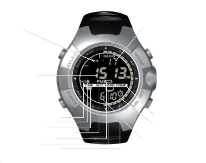
Figure 1.1
f)
SELECT
b)
QUICK
- Altitude Alarm Indicator
- Daily Alarm Indicator
- Mode Indicator
- AM/PM Indicator (12h display)
- Low Battery Indicator
- Use Indicator
- Chronometer Indicator
4
a)
MODE
PRESSURE
SENSOR
ON / OFF
d)
e)
c)

CHAPTER 1 INTRODUCTION
GENERAL INFORMATION
The Observer Wristop Computer is a reliable high precision electronic instrument, intended for
recreational use. The outdoor enthusiast who enjoys venturing in sports like skiing, kayaking,
mountain climbing, hiking and biking can rely on the Observers accuracy.
NOTE: The Observer should not be substituted for acquiring measurements that require
professional or industrial precision and should not be used to acquire measurements when
skydiving, hang gliding, paragliding, gyrocopter riding and flying small aircraft.
The Observer is available in three different material combinations:
Observer Sr with stainless steel housing and elastomer strap, Observer St with stainless steel
housing and stainless steel / elastomer bracelet and Observer Tt with Titanium housing and
Titanium / elastomer bracelets. All material versions have identical functions and operation.
CARE AND MAINTENANCE
Perform only the procedures discussed in this manual.
Never attempt to disassemble or service the Observer.
Protect your Observer from shocks, extreme heat and prolonged exposure to direct sunlight. If
not in use, your Observer should be stored in a clean, dry environment at room temperature.
The Observer can be wiped clean with a lightly moistened (warm water) cloth. Applying a mild
soap to the area can clean stubborn stains or marks.
Avoid exposing the Observer to strong chemicals like gasoline, cleaning solvents, acetone,
alcohol, insect repellents, adhesives, and paint, as they will damage the units seals, case and
finish.
Make sure the area around the sensors (located on the right of the instrument) is kept free of dirt
and sand. Never insert any objects into the sensor openings.
5
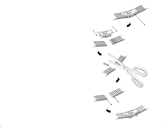
ADJUSTING THE BRACELET (ST AND TT MODELS)
The metal / elastomer bracelets of the Observer models St
and Tt have to be adjusted for the user. The steps are
1. Remove the buckle by releasing the spring bars with
pin, paper clip or other sharp object.
2. Remove both spring bars from the pin holes.
3. Shorten the bracelet by cutting along the grooves
on the inner surface of the bracelet. You can do this
for instance with scissors. If you are unsure of the
correct length, cut the pieces one by one and test
the length after cutting each piece. Cut in turns from
both sides of the bracelet to keep the sides equally
long. Be careful in order not to shorten the bracelet
too much.
4. Replace the spring bars into the last pin holes of
both sides of the bracelet.
5. Attach the buckle to the bracelet by placing the
spring bars into the holes in the buckle. In both sides
of the buckle are holes for two different positions.
This can be used for fine adjusting of the bracelet
length. Make sure that the spring bars are positioned
straight in the buckle.
6
æ
å
æ
å

KEY FEATURES
The Observer has four main modes: TIME, ALTIMETER, BAROMETER, and COMPASS.
In each of the features there are associated sub modes providing further enhancements to its
usefulness during your outdoor adventures. All key features and sub features will be discussed
in further detail following this chapter.
BACKLIGHT FEATURES
The Observer has an electroluminescent backlight. To activate the backlight, press and hold the
[MODE] button for 2 seconds. The backlight will remain on for approximately 10 seconds. If you
press buttons to operate, the backlight remains on 10 seconds from the last pressing.
WATER RESISTANCE
The Observer is water resistant up to 100m/330ft. However, it is not a diving instrument and
therefore the buttons should not be operated (put in use) while underwater.
BUTTON FUNCTIONS
The Observer is operated with four buttons as shown in Fig. 1.1: [MODE], [ON OFF], [QUICK],
and [SELECT].
The MODE Button
Located on the top right of the Observer performs the following functions:
A short press allows you to move from one mode to the next (TIME, ALTI, BARO, COMP).
While in the sub mode level, a short press returns you to the main mode.
During the setup process, a short press accepts all changes and exits the set function.
A long press of 2 seconds activates the backlight feature.
7

The ON OFF Button
Located on the bottom right of the Observer performs the following functions:
In the TIME Mode, the bottom field view can be scrolled displaying the calendar date,
seconds, or dual time.
During the setup process, a short press causes the selected value to increase.
For chronometer, a short press acts as a start/stop.
In ALTIMETER mode the logbook starts and stops with two short presses.
In the COMPASS mode, two short presses change between the normal compass and bearing
tracking feature.
The QUICK Button
Located on the bottom left of the Observer performs the following function:
In the setup process, pressing the [QUICK] button causes the selected value to decrease.
In the TIME, ALTIMETER, or BAROMETRIC mode, a short press quickly displays the
cumulative information of the current logbook recording. Refer to Chapter 3, Fast Cumula-
tive Features for more information
For chronometer, this button is used for lap times and zeroing.
In COMPASS mode, a short press locks the bearing.
The SELECT Button
Located on the top left of the Observer performs the following functions:
In a main mode level, a short press allows you to enter into the sub modes of the particular
function or return to the main mode.
For entering the setup process, a long press of 2 seconds allows you to initiate changes to the
Observers functions.
While in the setup process, a short press allows you to move between settable units or values
and determine preferences.
8

LCD DISPLAY
Designed to offer maximum clarity and simplicity the display is divided into several areas as
shown in Fig. 1.1.
a) The top field displays numbers or text depending on the mode or sub mode you are viewing.
b) The middle field displays large numbers and/or the related unit of measure of a function.
c) The bottom field displays either numbers and/or text.
d) The Mode Indictor Bar displays the main modes of the Observer. The half oblong
shape
shape
located just below the bar indicates the mode you are viewing. The half-moon
under the mode indicator indicates the Observer is being used as a barometer
(weather station) or altimeter.
e) The outer circumference of the LCD graphically tracks the units of measure based on the
selected mode.
f) On the top left, an arrow shaped Barometric Trend Indicator provides a quick refer-
ence view of weather conditions.
MEASUREMENTS AND UNITS
The Observer supplies two units of measure: Metric or Imperial. Each unit can be selected
individually.
Metric Unit of Measure Imperial Unit of Measure
mft
m/min ft/min
ºC ºF
hPa inHg
9

To set or check Unit of Measurement settings
If the mode indicator is not on TIME, press the [MODE] button until it is directly below TIME.
1. Press the [MODE] and [SELECT] buttons simultaneously for 3 seconds to enter the setup
mode. The top field will display SET momentarily and then change to UNI.
NOTE: Setup mode will automatically exit if left idle for more than one minute.
2. Press the [SELECT] button for 2 seconds to view the first setting. You will see the first unit
flashing.
WARNING: If you perform a short press of the [SELECT] button while in the UNI setting
mode, you will switch to Pressure Sensor Calibration. Refer to the next section for more details.
3. Press the [SELECT] button to move to the unit you want to change. You can change the
flashing unit. The units are in the following order: m/ft, m/min / ft/min, hPa/inHg, ºC/ºF.
4. Press the [ON OFF] or [QUICK] button to toggle between the metric and imperial settings.
5. To confirm the setting(s), press the [MODE] button.
6. To exit the setup process, press the [MODE] button again.
PRESSURE SENSOR CALIBRATION
WARNING: This is a FACTORY CALIBRATION SETTING. Do not enter this mode.
If you enter this mode in error, exit immediately by pressing the [MODE] or [SELECT] button
to return to the UNI setting mode. Normally there is no need to alter the calibration.
If the Pressure Setting Calibration has been altered, you can return the factory setting. Proceed
as follows: In the calibration setting mode, scroll the barometric pressure value up or down until
text REF appears. This is the factory setting. Then exit by pressing [MODE].
BATTERY REPLACEMENTS
The Observer operates on a three-volt lithium cell Type: CR 2032. The maximum life expectancy is approximately 12 months.
10
A low battery-warning indicator is activated when 5-15 percent of the battery capacity is still
available. When this occurs we recommend replacement of the battery.
Extreme cold weather will activate the low battery-warning indicator. Although the indicator is
activated, the battery may not need to be replaced due to this condition.
If the battery-warning indicator activates in temperatures above 10ºC (50ºF), replace the battery.
NOTE: Heavy use of the electroluminescent backlight,
altimeter, and compass will significantly reduce battery life.
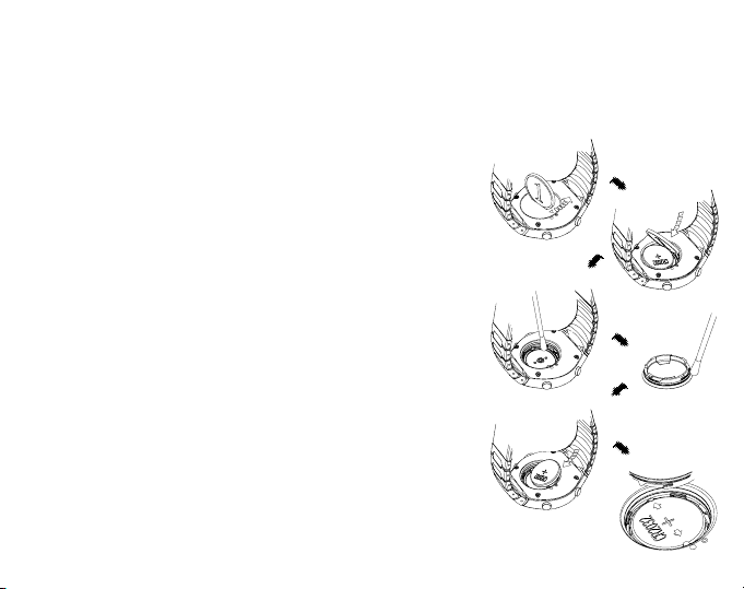
To replace the battery:
1. On the backside of the Observer, insert a coin into the
slot located on the battery compartment cover.
2. Turn the coin counterclockwise until it is aligned with
the open position marker, or even slightly further for
easy opening.
3. Remove the battery compartment cover. Ensure the oring and all surfaces are clean and dry. Dont stretch the
o-ring.
4. Remove the old battery carefully. Avoid bending the side
contacts.
5. Place the new battery into the battery compartment under
the side contacts with the positive side facing up.
6. With the o-ring in the correct position, replace the battery
compartment cover and turn it with the coin clockwise
until it is aligned with the close position marker.
NOTE: Battery replacement should be performed with
extreme care so as to ensure the Observer continues to
remain waterproof. It is your responsibility to ensure that
the Observer remains waterproof.
æ
å
æ
å
æ
11

After every battery replacement, it is necessary to calibrate the magnetic sensor. Refer to Chapter
5, Calibrating the Compass.
CHAPTER 2 TIME MODE
There are three time submodes: time, chronometer and alarms.
NOTE: These functions are accessible in the TIME mode, i.e. when the mode indictor is below
TIME.
In the watch time mode, the fields display the following data as shown in Fig. 2.1:
a) Day of the week;
b) Current time;
c) Date dd.mm in 24h display or mm.dd in 12h display, seconds or dual time according to the
last selection (changing data with the [ON OFF] button;
d) Am/pm indicator in 12 h display; and
e) Graphical display of seconds, once every two seconds a new segment lights up until a full
circle of segments (60 seconds) is lit.
SETTING UP THE TIME AND CALENDAR FUNCTIONS
1. In the main mode of the time function, press the [SELECT] button for 2 seconds to begin the
setup process. In the bottom field, seconds will begin to flash.
2. Press the [SELECT] button to move to the field you want to change. The order of fields is
seconds, minutes, hours, 12/24h, year, month, day, dual-time hours, dual-time minutes. You
change the value in the field that is flashing.
3. Press the [ON OFF] button to scroll the value in the field up or the [QUICK] button to scroll
down. In the seconds field, the [QUICK] button resets the seconds to zero.
4. Press the [MODE] button to accept the changes made and exit the setup process.
12
 Loading...